JP3962692B2 - Air vent fan - Google Patents
Air vent fan Download PDFInfo
- Publication number
- JP3962692B2 JP3962692B2 JP2002591730A JP2002591730A JP3962692B2 JP 3962692 B2 JP3962692 B2 JP 3962692B2 JP 2002591730 A JP2002591730 A JP 2002591730A JP 2002591730 A JP2002591730 A JP 2002591730A JP 3962692 B2 JP3962692 B2 JP 3962692B2
- Authority
- JP
- Japan
- Prior art keywords
- shell
- intake
- blade
- axis
- air
- Prior art date
- Legal status (The legal status is an assumption and is not a legal conclusion. Google has not performed a legal analysis and makes no representation as to the accuracy of the status listed.)
- Expired - Fee Related
Links
Images


Classifications
-
- F—MECHANICAL ENGINEERING; LIGHTING; HEATING; WEAPONS; BLASTING
- F04—POSITIVE - DISPLACEMENT MACHINES FOR LIQUIDS; PUMPS FOR LIQUIDS OR ELASTIC FLUIDS
- F04D—NON-POSITIVE-DISPLACEMENT PUMPS
- F04D29/00—Details, component parts, or accessories
- F04D29/40—Casings; Connections of working fluid
- F04D29/42—Casings; Connections of working fluid for radial or helico-centrifugal pumps
- F04D29/44—Fluid-guiding means, e.g. diffusers
- F04D29/441—Fluid-guiding means, e.g. diffusers especially adapted for elastic fluid pumps
- F04D29/444—Bladed diffusers
-
- F—MECHANICAL ENGINEERING; LIGHTING; HEATING; WEAPONS; BLASTING
- F04—POSITIVE - DISPLACEMENT MACHINES FOR LIQUIDS; PUMPS FOR LIQUIDS OR ELASTIC FLUIDS
- F04D—NON-POSITIVE-DISPLACEMENT PUMPS
- F04D17/00—Radial-flow pumps, e.g. centrifugal pumps; Helico-centrifugal pumps
- F04D17/08—Centrifugal pumps
- F04D17/16—Centrifugal pumps for displacing without appreciable compression
- F04D17/165—Axial entry and discharge
-
- F—MECHANICAL ENGINEERING; LIGHTING; HEATING; WEAPONS; BLASTING
- F24—HEATING; RANGES; VENTILATING
- F24F—AIR-CONDITIONING; AIR-HUMIDIFICATION; VENTILATION; USE OF AIR CURRENTS FOR SCREENING
- F24F7/00—Ventilation
- F24F7/02—Roof ventilation
- F24F7/025—Roof ventilation with forced air circulation by means of a built-in ventilator
-
- F—MECHANICAL ENGINEERING; LIGHTING; HEATING; WEAPONS; BLASTING
- F24—HEATING; RANGES; VENTILATING
- F24F—AIR-CONDITIONING; AIR-HUMIDIFICATION; VENTILATION; USE OF AIR CURRENTS FOR SCREENING
- F24F7/00—Ventilation
- F24F2007/001—Ventilation with exhausting air ducts
Landscapes
- Engineering & Computer Science (AREA)
- Mechanical Engineering (AREA)
- General Engineering & Computer Science (AREA)
- Combustion & Propulsion (AREA)
- Chemical & Material Sciences (AREA)
- Structures Of Non-Positive Displacement Pumps (AREA)
- Gas Separation By Absorption (AREA)
- Jet Pumps And Other Pumps (AREA)
- Percussion Or Vibration Massage (AREA)
- Ventilation (AREA)
- Cooling Or The Like Of Electrical Apparatus (AREA)
- Duct Arrangements (AREA)
- Chimneys And Flues (AREA)
- Catching Or Destruction (AREA)
Abstract
Description
本発明は、室内の空気を入れ替えるため、少なくとも一つの部屋から空気を抜き取るダクトに関連して設計されたファンに関するものである。 The present invention relates to a fan designed in connection with a duct that draws air from at least one room in order to replace room air.
住居または事務所用に使用されている多くの部屋は、部屋を良い状態に保つ目的で、空気の入れ替えを行う装置を有している。なぜなら部屋は、確実にそれらの構成材料がそれらの特性を保ち、また占有者に快適性をもたらすことを目的に、換気しなければならないからである。 Many rooms used for residences or offices have a device for changing air in order to keep the room in good condition. This is because the room must be ventilated in order to ensure that their constituent materials retain their properties and provide comfort to the occupants.
今日、部屋は一般的に制御可能な機械換気装置を備えており、そのような装置は、台所のような衛生的な調理設備、浴室、便所などを含んだ部屋から一定量の空気を抜き取るために設計された、抜き取りユニットを備え、抜き取られた空気と同じ量が、居間または寝室のような生活設備の中に、それらの部屋に具備された空気取入部を介して、入れられている。 Today, rooms are generally equipped with mechanical ventilators that can be controlled, and such devices are used to extract a certain amount of air from rooms containing sanitary cooking facilities such as kitchens, bathrooms, toilets, etc. The same amount of extracted air is put into a living facility such as a living room or bedroom through an air intake provided in those rooms.
特に古い建物において実施される別の解決手段は、大きな断面のダクトに通じ、屋根の高さで開口する、衛生的な調理設備の空気引出し部を備えて構成されており、風と熱循環(thermal circulation)による起動圧力の空気が充分である時、例えばこの起動圧力が、部屋の内部と外部との間の10℃の温度差と、3m/sの風との複合作用によって、発生させられたものよりも大きい時、自然の通風によって抜き取られる。室外の温度が、室内の温度温度よりも充分に高い時、自然の通風が、冬季に充分な結果をもたらすことができる。しかし夏季では、温度が逆転し、空気を逆方向に循環させ、言い換れば普通は抜き取りのために使用されるダクトを介して、空気が入ってくる。 Another solution, particularly implemented in older buildings, consists of a hygienic cooking facility air outlet that leads to a duct with a large cross-section and opens at the height of the roof. When the starting pressure air due to thermal circulation is sufficient, for example, this starting pressure is generated by the combined action of a 10 ° C temperature difference between the inside and outside of the room and the wind of 3m / s. When it is larger than the one, it is extracted by natural ventilation. When the outdoor temperature is sufficiently higher than the indoor temperature temperature, natural ventilation can produce satisfactory results in winter. In summer, however, the temperature reverses and air circulates in the opposite direction, in other words, air enters through the duct normally used for extraction.
従って、ダクトにファンを具備すると有利であり、自然の通気が不充分である時、特に夏季に、ファンのシャフトから外向きに伸びた複数のブレードを有する軸上のファンを利用することによって、補足的な起動圧力をもたらし、それらのブレードは空気を変位させる斜面を有している。しかし、ファンを駆動させるために、相当な量の起動力を与えなければならず、自然の通気によって空気を入れ替えできるように、ファンが静止している時、ブレードは抜き取られる空気の流れをかなり制限するのに充分な圧力低下を発生させる。 Therefore, it would be advantageous to have a fan in the duct, and by utilizing an on-axis fan having a plurality of blades extending outwardly from the fan shaft, especially in the summer when natural ventilation is insufficient, These blades have ramps that displace air, providing a complementary starting pressure. However, to drive the fan, a significant amount of starting force must be applied, and when the fan is stationary, the blades can draw a significant amount of air flow when the fan is stationary so that the air can be replaced by natural ventilation. Generate a pressure drop sufficient to limit.
本発明の目的は、空気抜き取りダクトに備えるように設計されたファンを提供することであり、その構造はファンが静止して、すなわち自然の通気によって空気を抜き取る時、ファンがごく僅かな圧力低下を発生させるだけで、また動作中に、例えば内部と外部との間の15℃の温度差と風速4m/sに対応する、普通の自然な通気で得られた空気の流れに匹敵する空気の流れを与え、それがもし必要でも、ファンの近くの屋根に配置されたソーラーパネルによって、供給できるほど、電力消費量が非常に低い。本発明の目的は従って、永久に自然エネルギー、言い換えれば特に冬季と中間の季節において、風と熱循環による起動圧力で、また夏季においてファンモーターに供給される太陽エネルギーで、運転する装置を提供することである。 It is an object of the present invention to provide a fan designed to provide for an air extraction duct whose structure causes a slight pressure drop when the fan is stationary, i.e. when the air is extracted by natural ventilation. During operation, for example, a 15 ° C temperature difference between the inside and outside and a wind speed of 4 m / s, comparable to the air flow obtained with normal natural ventilation. If it is necessary, the power consumption is so low that it can be supplied by solar panels placed on the roof near the fan, if necessary. The object of the present invention is therefore to provide a device that operates permanently with natural energy, in other words in the winter and intermediate seasons, with the starting pressure by wind and heat circulation and with the solar energy supplied to the fan motor in the summer. That is.
この目的のため、ファンは本発明で請求されているように;
円筒形シェルを備え、その取入部が、より小さな直径の同軸の円筒形ダクトに放射状の肩部によって接続され;
シェルに対して軸線方向に取り付けられ、且つシェルの直径に関して小さな直径を有した電動モーターを備え、複数のブレードから成る回転翼が、モーターシャフトに固定され、各ブレードは、シェルの軸線と平行な平面上の一つのブレードの横断面全体が、前記軸線に対して平行であり、複数のブレードの最大直径が、シェルの直径と、シェルの取入部の直径との間にあり、取入端部から別の端部へ下向きに、言い換えれば取入端部から別の端部へ小さくなっており、そして、
シェル(6)の内表面と一体型で、シェルの周縁部にかけて分配され、各々に少なくとも一つの湾曲部(19a)を具備した、複数の空気案内翼(19)を備え、湾曲部(19a)が、シェルの取入端部に配置され、且つシェル(6)と、空気取入部(8)に延びる実質的な円筒形の表面との間の環状空間に収容される。
For this purpose, the fan is as claimed in the present invention;
Comprising a cylindrical shell, the intake of which is connected by a radial shoulder to a smaller diameter coaxial cylindrical duct;
An electric motor mounted axially with respect to the shell and having a small diameter with respect to the diameter of the shell, a rotor blade comprising a plurality of blades is fixed to the motor shaft, each blade being parallel to the axis of the shell The entire cross-section of one blade on the plane is parallel to the axis, and the maximum diameter of the plurality of blades is between the diameter of the shell and the diameter of the intake portion of the shell; From one end to the other, in other words, from the intake end to the other end, and
A plurality of air guide vanes (19), integral with the inner surface of the shell (6), distributed over the periphery of the shell and each comprising at least one curved portion (19a), the curved portion (19a) Is accommodated in an annular space between the shell (6) and a substantially cylindrical surface extending to the air intake (8) and arranged at the intake end of the shell.
ファン回転翼のブレードの形状により、それらのブレードは単に非常に低い抵抗を空気の流れに与えて、モーターを停止すると、ほんの小さな圧力低下を生じさせる。複数の案内翼に関して、その湾曲部は空気の流れの外の領域に配置されており、それはシェルの取入表面が、シェルの表面よりも小さいからである。しかし、本発明において請求されたファンは、電動モーターが回転翼を駆動させる時、高い効力をもたらすようになっており、それは回転翼によって動かされた空気が、上流から下流へ空気を向ける複数の案内翼に当たるからである。このファンの効力は、とても高く、モーターに太陽エネルギーで供給できるほど、その消費量は少ない。 Due to the shape of the fan rotor blades, they simply provide a very low resistance to the air flow and cause only a small pressure drop when the motor is stopped. For a plurality of guide vanes, the curvature is located in a region outside the air flow because the intake surface of the shell is smaller than the surface of the shell. However, the fan claimed in the present invention is designed to be highly effective when the electric motor drives the rotor blades, which means that the air driven by the rotor blades is directed to a plurality of air streams that direct the air from upstream to downstream. This is because it hits the guide wing. This fan is very effective, and its consumption is so low that it can be supplied to the motor by solar energy.
このファンの一実施形態において、各ブレードが平らで、シェルの軸線を含んだ長手平面上に位置している。 In one embodiment of the fan, each blade is flat and lies on a longitudinal plane that includes the axis of the shell.
可能な実施形態において、各ブレードがシェルの軸線に対し垂直で、更に上流に配置されたブレードの引出し縁部のポイントから延びる、取入縁部を有する。 In a possible embodiment, each blade has an intake edge that is perpendicular to the axis of the shell and extends further from the point of the blade's drawer edge located upstream.
各ブレードの引出し縁部は、取入縁部とのその接合部の高さにあるシェルの軸線から、最大間隔であり、そして下流方向に前記シェルの軸線に次第に席巻する湾曲部に続く。 The leading edge of each blade follows a curve that is the maximum distance from the axis of the shell at the level of its junction with the intake edge and that gradually swoops downstream of the axis of the shell.
そのような場合、各ブレードの表面領域が下流方向へ減少する。 In such a case, the surface area of each blade decreases in the downstream direction.
別の可能な実施形態において、各ブレードが、シェルの軸線に対して垂直で、更に上流に配置されたブレードの引出し縁部のポイントから、シェルの半径の一部分にかけて延びた、取入縁部を有しており、この縁部は下流へ内向きに走る縁部によって延ばされており、ゆえにブレードを半三日月の一般的な形状に画定する。 In another possible embodiment, each blade has an intake edge extending from a point of the blade's drawer edge that is perpendicular to the axis of the shell and further upstream to a portion of the radius of the shell. And this edge is extended by an edge that runs inwardly downstream, thus defining the blade in the general shape of a half crescent.
ゆえに、下流方向に幅が少なくなるブレードを有することができる。 Therefore, it is possible to have a blade whose width decreases in the downstream direction.
本発明の別の特徴によると、各案内翼の上流端部が、複数のブレードの引出し縁部の上流部分にある通路の近くに配置されており、各翼は、湾曲部分、言い換えるとシェルに関して軸線方向に延びない部分を有し、方角が回転翼のブレードから出た空気ジェットの方角に似た迎え角を有し、ファンが静止した時、自然の通気状態で主要な流れの外に配置され、例えばシェルの取入部の直径とほぼ等しい長さにわたって延びており、各湾曲部分がシェルの軸線に対して平行な平坦部分によって、下流方向へ延びる。 According to another characteristic of the invention, the upstream end of each guide vane is arranged near a passage in the upstream part of the leading edge of the plurality of blades, each vane being in relation to a curved part, in other words a shell. It has a non-axially extending part, and its direction has an angle of attack similar to the direction of the air jet coming out of the blades of the rotor blades, and is placed outside the main flow in natural ventilation when the fan is stationary For example, extending over a length approximately equal to the diameter of the shell intake, with each curved portion extending downstream by a flat portion parallel to the axis of the shell.
自然の通気状態において、取入部の高さにある空気の流れが、取入部の横断面を占めて、少し下流にだけ、取入部の直径と等しい距離にわたって広げられる。従って複数の案内翼湾曲部分は、空気の流れの動揺を実際に生じさせない。この距離を越えて、空気の流れがそれと平行で且つ、ほんの僅かな程度だけ空気の流れを妨害する、複数の翼の一部分に接触する。この高さで、複数の翼はより幅広くでき、その内側部分がシェルの取入部の伸長部に配置された、実際のシリンダーに入ることができる。 In the natural ventilation state, the air flow at the height of the intake occupies the cross section of the intake and is spread only a little downstream, over a distance equal to the diameter of the intake. Accordingly, the plurality of guide blade curved portions do not actually cause fluctuations in the air flow. Beyond this distance, the air flow contacts a portion of the plurality of wings that are parallel to it and impede the air flow only to a slight extent. At this height, the wings can be made wider and can enter the actual cylinder, whose inner part is located in the extension of the intake of the shell.
いかなる場合でも本発明は、このファンの実施例を、それに制限することを意図しないで、示した添付図面に関連した、以下の記載から明らかになるであろう。 In any event, the present invention will become apparent from the following description, taken in conjunction with the accompanying drawings, which are not intended to limit the embodiment of this fan.
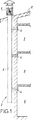
一般的に符号2によって示され、複数の重なり合った部屋3を持った建物を示しており、各部屋は少なくとも一つの引出し部4を有しており、引出し部は建物の屋根11の高さで開口した、垂直換気ダクト5に連通している。ダクト5の上部分は、より大きな外径を有した円筒形シェル6に接続され、シェルの内部分が、放射状肩部7によってダクトに接合されている。ゆえにシェルの引出し部8は、ダクトの横断面と同一の横断面を有しており、それはシェル6の横断面よりも小さい。電動モーター10は、シェルの横断面よりもかなり小さな横断面を有しており、それはシェル6に複数の放射方向バー9によって固定されており、モーター本体の直径は、例えばシェルの直径の10%〜20%の間である。複数のブレード14を有する回転翼13は、モーターのシャフト12に留められており、モーターはシェル6に関して中心に位置し且つ同軸である。各ブレードは、平らなプレートから成っており、その取入縁部15は、シェルの軸線に対して垂直で、その引出し縁部16は、下流方向にシェルの軸線に次第に近づいている。各ブレード14の取入縁部15の外端部17が、放射状肩部7に面していることは明らかである。縁部15と肩部7との間の間隙は、可能な限り小さくなっている。変形例において、各ブレードはシェルの軸線に対して垂直な外部分を有した取入縁部15を有しており、それは下流方向へ、図2及び図3に示された別の部分によって延びており、縁部すなわち曲線18が、ブレードを半三日月の一般的な形状に形成して、その幅が下流方向へ増えている。
Generally indicated by
空気の流れに関する案内翼19は、回転翼へ向かって、それよりも下流でシェル6の壁上に固定されている。各翼19は、取入部の直径にほぼ等しい取入部8から、距離をあけて延びている第一部分19aを有している。翼の一部分19aは、円筒形シェル6とシェルの取入部8に延びる実際のシリンダーとによって画定された、空間に収容されており、その一部分は曲がって、迎え角の方位を有しており、その方位が回転翼のブレードから出る空気の噴射の方位と似ている。この部分19aは、シェルの軸線に平行な平坦部分19bによって下流方向に延ばされている。
The guide vanes 19 relating to the air flow are fixed on the wall of the shell 6 toward the rotary vanes and further downstream. Each
この装置は以下の方法で動作する。 This device operates in the following manner.
自然の通気方向では、静止回転翼13の取入部における空気の流れは、ブレード14の平面部に平行であり、流れをそらすことのない前記回転翼を介する通路は、空気の通過を僅かに妨害する。
In the natural ventilation direction, the air flow at the intake of the
そのインテリアのため、全体の取入横断面を占める空気の流れには、それが案内翼の曲部分の下流に達するまで、重大な膨張がないことは明らかである。特にシェルの軸線に平行な平坦部分を除いて、空気の流れとそれらの翼との間に、接触がなく、空気の流れに対して非常に小さな妨害があるだけである。 Due to its interior, it is clear that the air flow occupying the entire intake cross section is not significantly expanded until it reaches downstream of the curved portion of the guide vane. There is no contact between the air flow and their wings, except in particular the flat part parallel to the axis of the shell, and there is only a very small disturbance to the air flow.
ファンが作動中の時、回転翼の取出し部における空気の流れの速度Vsは、取入速度Veと、その取出しポイントにおける高さでの回転翼の回転速度Vrの結果に近似である事は明らかであろう。 When the fan is in operation, it is clear that the velocity Vs of air flow at the take-out part of the rotor blade is close to the result of the intake velocity Ve and the rotor blade speed Vr at the height at the take-off point. Will.
回転翼は、この流れの空気に、0.5×ρ×Vr2と等しい運動エネルギーを、動的圧力を加えることができ、ここでρは空気の濃度である。 The rotor can apply dynamic pressure to this flow of air with kinetic energy equal to 0.5 × ρ × Vr 2 , where ρ is the concentration of air.
シェルの軸線からの距離が増すと、速度Vrも増し、空気に加わる動的圧力が強められ、空気の方角がシェルの壁に向かって、だんだんとそらされる。 As the distance from the shell axis increases, the velocity Vr also increases, increasing the dynamic pressure applied to the air and gradually diverting the direction of the air toward the shell wall.
取入案内翼19aは、回転翼13を出た最速の周辺空気噴射を、それらの回転動作をファンによって与えられる有利な出力と圧力を増やす、縦の変位に次第に変換するように向ける。回転翼の軸線に最も近い部分から出る流れにより、そのエネルギーの最も強い動的圧力の割り当て部分を有する、それらの案内流が、誘導の際に、より規則的な方法でシェルの全通過表面を占める。
The intake guide vanes 19a direct the fastest ambient air jets exiting the
回転翼13の直径が、空気の循環を所望の方向に促すため、下流の方向に減っていることは明らかである。大きな直径を有する上流部分が、下流部分よりも空気に更に圧力を加える。この構成は、回転翼13とシェル6との間に設けられた通路を次第に増やして、取入部8からの距離が増える際に、回転翼から出る空気の増量分に適応させることも可能である。
Obviously, the diameter of the
回転翼13を介する通路と、結果的に空気に作用するための時間は、軸線に近づくと、その長さが増える。空気を駆動させる速度は従って、軸線に近づくと、回転翼の速度に近づくようになる。この解決手段は、周辺部分と、過剰な戻り流を生じさせ得る中心部分との間に、圧力差を少なくする。
The length of the passage through the
上記が示すように、本発明は簡単な構造を有するファンを提供することによって、従来技術を大きく改善しており、それはブレードが圧力低下を小さくすることと、ファンが静止している時、案内翼の湾曲部が空気の流れの外に置くだけである。従って、温度及び風の状態が差し支えない時、自然の換気によって空気の抜き取りを行うことを可能にする。温度及び風の状態が、充分な自然の換気を生じさせない時、ファンが非常に低い電気消費量で、空気の抜き取りを行うことができ、電動モーターに太陽エネルギーを供給することを可能にする。 As indicated above, the present invention greatly improves the prior art by providing a fan with a simple structure, which reduces the pressure drop by the blade and guides the fan when it is stationary. The curved part of the wing is simply placed outside the air flow. Therefore, it is possible to extract air by natural ventilation when the temperature and wind conditions are acceptable. When the temperature and wind conditions do not produce sufficient natural ventilation, the fan can be evacuated with very low electricity consumption, allowing solar power to be supplied to the electric motor.
明らかなように、本発明は上記に一例として示されたファンの実施例に限定されることはないが、すべての変形実施例を含んでいる。ゆえに、本発明の範囲内で、特にブレードの形状に関して変えること、各ブレードに関して平らにしないことは可能であろう。 As will be apparent, the invention is not limited to the fan embodiment shown by way of example above, but includes all variants . Thus, within the scope of the present invention, it may be possible to vary particularly with respect to the shape of the blades and not to be flat with respect to each blade.
Claims (5)
円筒形シェル(6)を備え、その取入部(8)が、より小さな直径の同軸の円筒形ダクト(5)に放射状の肩部(7)によって接続され;
シェル(6)に対して軸線方向に取り付けられ、且つシェルの直径に関して小さな直径を有した電動モーターを備え、複数のブレード(14)から成る回転翼が、モーターシャフトに固定され、各ブレードは、シェルの軸線と平行な平面上の一つのブレードの横断面全体が、前記軸線に対して平行であり、複数のブレード(14)の最大直径が、シェル(6)の直径と、シェルの取入部(8)の直径との間にあり、取入端部から別の端部へ下向きに、言い換えれば取入端部から電動モーターのシャフト(12)へ小さくなっており、そして、
シェル(6)の内表面と一体型で、シェルの周縁部にかけて分配され、各々に少なくとも一つの湾曲部(19a)を具備した、複数の空気案内翼(19)を備え、湾曲部が、シェルの取入端部に配置され、且つシェル(6)と、空気取入部(8)を延ばした仮想の円筒形表面との間の環状空間に収容され、シェル(6)の軸線に平行な平坦部分(19b)に繋がること、
を特徴とするファン。In a fan designed for a duct that draws air from at least one room to replace the air in the room,
Comprising a cylindrical shell (6), the intake (8) of which is connected by a radial shoulder (7) to a smaller diameter coaxial cylindrical duct (5);
An electric motor mounted axially relative to the shell (6) and having a small diameter with respect to the diameter of the shell, a rotor blade comprising a plurality of blades (14) is fixed to the motor shaft, each blade being The entire cross section of one blade on a plane parallel to the axis of the shell is parallel to the axis, and the maximum diameter of the plurality of blades (14) is the diameter of the shell (6) and the intake of the shell. Between the diameter of (8) and downward from the intake end to another end, in other words, from the intake end to the electric motor shaft (12), and
A plurality of air guide vanes (19), integral with the inner surface of the shell (6), distributed over the periphery of the shell and each comprising at least one curved portion (19a), the curved portion being a shell And is accommodated in an annular space between the shell (6) and an imaginary cylindrical surface extending the air intake (8) and parallel to the axis of the shell (6) Connected to part (19b),
A fan that features.
Applications Claiming Priority (2)
| Application Number | Priority Date | Filing Date | Title |
|---|---|---|---|
| FR0106738A FR2825142B1 (en) | 2001-05-22 | 2001-05-22 | FAN INTENDED TO BE ASSOCIATED WITH AN AIR EXHAUST DUCT OUTSIDE AT LEAST ONE PREMISES |
| PCT/FR2002/001706 WO2002095298A1 (en) | 2001-05-22 | 2002-05-21 | Air evacuating ventilator |
Publications (2)
| Publication Number | Publication Date |
|---|---|
| JP2004525338A JP2004525338A (en) | 2004-08-19 |
| JP3962692B2 true JP3962692B2 (en) | 2007-08-22 |
Family
ID=8863550
Family Applications (1)
| Application Number | Title | Priority Date | Filing Date |
|---|---|---|---|
| JP2002591730A Expired - Fee Related JP3962692B2 (en) | 2001-05-22 | 2002-05-21 | Air vent fan |
Country Status (15)
| Country | Link |
|---|---|
| US (1) | US6814661B2 (en) |
| EP (1) | EP1389288B1 (en) |
| JP (1) | JP3962692B2 (en) |
| AT (1) | ATE295951T1 (en) |
| CA (1) | CA2447421C (en) |
| DE (1) | DE60204223T2 (en) |
| DK (1) | DK1389288T3 (en) |
| ES (1) | ES2242040T3 (en) |
| FR (1) | FR2825142B1 (en) |
| LT (1) | LT5171B (en) |
| MA (1) | MA26113A1 (en) |
| PL (1) | PL204058B1 (en) |
| RU (1) | RU2287088C2 (en) |
| TN (1) | TNSN03115A1 (en) |
| WO (1) | WO2002095298A1 (en) |
Families Citing this family (9)
| Publication number | Priority date | Publication date | Assignee | Title |
|---|---|---|---|---|
| KR100529002B1 (en) * | 2003-12-31 | 2005-11-15 | 학교법인 포항공과대학교 | Local exhaust ventilation system with covered rotating swirler |
| US7682231B2 (en) | 2004-01-20 | 2010-03-23 | Greenheck Fan Corporation | Exhaust fan assembly |
| US7320636B2 (en) * | 2004-01-20 | 2008-01-22 | Greenheck Fan Corporation | Exhaust fan assembly having flexible coupling |
| EP1794507B1 (en) * | 2004-09-23 | 2013-05-01 | CSR Building Products Limited | Hybrid ventilator |
| US7455582B2 (en) * | 2005-11-30 | 2008-11-25 | Barrett Cory G | Solar powered fan for portable enclosure |
| DE102007055507A1 (en) * | 2007-11-21 | 2009-06-04 | Georg Emanuel Koppenwallner | Bevel lip spiral |
| CZ304101B6 (en) * | 2012-03-14 | 2013-10-23 | Morávek@Petr | Air-conditioning plant with a free runner built-in round conduit |
| RU183910U1 (en) * | 2018-05-31 | 2018-10-08 | федеральное государственное бюджетное образовательное учреждение высшего образования "Ульяновский государственный технический университет" | ROOM VENTILATION DEVICE |
| KR102611669B1 (en) * | 2022-03-24 | 2023-12-07 | 박태업 | Ventilation apparatus for building duct |
Family Cites Families (9)
| Publication number | Priority date | Publication date | Assignee | Title |
|---|---|---|---|---|
| US1958145A (en) * | 1932-05-23 | 1934-05-08 | Jones William Anthony | Fan |
| US2397171A (en) * | 1943-12-06 | 1946-03-26 | Del Conveyor & Mfg Company | Fan and motor mounting |
| CH399698A (en) * | 1963-04-11 | 1965-09-30 | Rimann Kurt | Roof fan |
| US3329415A (en) * | 1964-12-21 | 1967-07-04 | Chicago Eastern Corp | Blower cooler |
| DK118475B (en) * | 1965-08-02 | 1970-08-24 | Nordisk Ventilator | Radial fan with axial outflow. |
| US5246339A (en) * | 1988-06-08 | 1993-09-21 | Abb Flakt Ab | Guide vane for an axial fan |
| DE19510811A1 (en) * | 1995-03-24 | 1996-09-26 | Klein Schanzlin & Becker Ag | Fiber-repellent wall surface design |
| FR2782781B1 (en) * | 1998-09-02 | 2000-09-29 | Andre Amphoux | SAFETY DEVICE FOR GAS EVACUATION SYSTEMS |
| US6733240B2 (en) * | 2001-07-18 | 2004-05-11 | General Electric Company | Serrated fan blade |
-
2001
- 2001-05-22 FR FR0106738A patent/FR2825142B1/en not_active Expired - Lifetime
-
2002
- 2002-05-21 EP EP02745463A patent/EP1389288B1/en not_active Expired - Lifetime
- 2002-05-21 DE DE60204223T patent/DE60204223T2/en not_active Expired - Lifetime
- 2002-05-21 AT AT02745463T patent/ATE295951T1/en not_active IP Right Cessation
- 2002-05-21 RU RU2003134011/06A patent/RU2287088C2/en active
- 2002-05-21 WO PCT/FR2002/001706 patent/WO2002095298A1/en active IP Right Grant
- 2002-05-21 PL PL363833A patent/PL204058B1/en unknown
- 2002-05-21 JP JP2002591730A patent/JP3962692B2/en not_active Expired - Fee Related
- 2002-05-21 ES ES02745463T patent/ES2242040T3/en not_active Expired - Lifetime
- 2002-05-21 US US10/477,184 patent/US6814661B2/en not_active Expired - Fee Related
- 2002-05-21 CA CA002447421A patent/CA2447421C/en not_active Expired - Fee Related
- 2002-05-21 DK DK02745463T patent/DK1389288T3/en active
- 2002-05-22 TN TNPCT/FR2002/001706A patent/TNSN03115A1/en unknown
-
2003
- 2003-11-12 LT LT2003097A patent/LT5171B/en not_active IP Right Cessation
- 2003-11-21 MA MA27412A patent/MA26113A1/en unknown
Also Published As
| Publication number | Publication date |
|---|---|
| DE60204223D1 (en) | 2005-06-23 |
| DK1389288T3 (en) | 2005-09-19 |
| WO2002095298A1 (en) | 2002-11-28 |
| MA26113A1 (en) | 2004-04-01 |
| PL363833A1 (en) | 2004-11-29 |
| CA2447421A1 (en) | 2002-11-28 |
| FR2825142B1 (en) | 2003-08-29 |
| US6814661B2 (en) | 2004-11-09 |
| JP2004525338A (en) | 2004-08-19 |
| LT5171B (en) | 2004-10-25 |
| TNSN03115A1 (en) | 2005-04-08 |
| ATE295951T1 (en) | 2005-06-15 |
| EP1389288A1 (en) | 2004-02-18 |
| FR2825142A1 (en) | 2002-11-29 |
| ES2242040T3 (en) | 2005-11-01 |
| RU2003134011A (en) | 2005-05-10 |
| PL204058B1 (en) | 2009-12-31 |
| LT2003097A (en) | 2004-06-25 |
| CA2447421C (en) | 2008-12-30 |
| DE60204223T2 (en) | 2006-01-26 |
| RU2287088C2 (en) | 2006-11-10 |
| EP1389288B1 (en) | 2005-05-18 |
| US20040132400A1 (en) | 2004-07-08 |
Similar Documents
| Publication | Publication Date | Title |
|---|---|---|
| CN100593674C (en) | Air conditioner | |
| JP5030106B2 (en) | Blower | |
| CN106765577B (en) | Fresh air assembly capable of discharging air annularly and air conditioner | |
| US4944654A (en) | Split scroll for centrifugal blower | |
| JP3962692B2 (en) | Air vent fan | |
| US11536284B2 (en) | Ceiling fan | |
| JP2011226482A (en) | Tunnel power turbine system to generate potential energy from waste kinetic energy | |
| US10309667B2 (en) | Ventilator | |
| JP4151851B1 (en) | Wind exhaust system | |
| CN208475464U (en) | Air outlet duct structure and air conditioner | |
| EP3704385B1 (en) | Fan | |
| CN103562647B (en) | Ventilation unit | |
| CN100460688C (en) | Eccentric fan for indoor cabinet air conditioner | |
| CN2379626Y (en) | Double air flow air conditioning installation | |
| EP3889436A1 (en) | Fans for ventilation | |
| CN113027824B (en) | Impeller type intelligent ventilation and noise reduction device and use method thereof | |
| US20180283713A1 (en) | Fluid actuated fluid extraction system | |
| CN213808154U (en) | Fan device and air condensing units | |
| KR102022852B1 (en) | Method For Installing Fan And Blower Apparatus Using The Method | |
| KR100691636B1 (en) | Hybrid ventilation system | |
| CN211422988U (en) | Sports bladeless neck hanging fan | |
| CN218377043U (en) | Air guide device for fan noise reduction and fan | |
| WO2023188263A1 (en) | Vertical wind speed-accelerating windmill | |
| JP2007247548A (en) | Blower device, air conditioning device and humidifying unit provided with same | |
| JPH0322656Y2 (en) |
Legal Events
| Date | Code | Title | Description |
|---|---|---|---|
| A621 | Written request for application examination |
Free format text: JAPANESE INTERMEDIATE CODE: A621 Effective date: 20050520 |
|
| A977 | Report on retrieval |
Free format text: JAPANESE INTERMEDIATE CODE: A971007 Effective date: 20060120 |
|
| A131 | Notification of reasons for refusal |
Free format text: JAPANESE INTERMEDIATE CODE: A131 Effective date: 20060131 |
|
| A601 | Written request for extension of time |
Free format text: JAPANESE INTERMEDIATE CODE: A601 Effective date: 20060501 |
|
| A602 | Written permission of extension of time |
Free format text: JAPANESE INTERMEDIATE CODE: A602 Effective date: 20060601 |
|
| A521 | Request for written amendment filed |
Free format text: JAPANESE INTERMEDIATE CODE: A523 Effective date: 20060609 |
|
| A131 | Notification of reasons for refusal |
Free format text: JAPANESE INTERMEDIATE CODE: A131 Effective date: 20060830 |
|
| A601 | Written request for extension of time |
Free format text: JAPANESE INTERMEDIATE CODE: A601 Effective date: 20061130 |
|
| A602 | Written permission of extension of time |
Free format text: JAPANESE INTERMEDIATE CODE: A602 Effective date: 20070126 |
|
| A521 | Request for written amendment filed |
Free format text: JAPANESE INTERMEDIATE CODE: A523 Effective date: 20070228 |
|
| TRDD | Decision of grant or rejection written | ||
| A01 | Written decision to grant a patent or to grant a registration (utility model) |
Free format text: JAPANESE INTERMEDIATE CODE: A01 Effective date: 20070425 |
|
| A61 | First payment of annual fees (during grant procedure) |
Free format text: JAPANESE INTERMEDIATE CODE: A61 Effective date: 20070521 |
|
| R150 | Certificate of patent or registration of utility model |
Free format text: JAPANESE INTERMEDIATE CODE: R150 |
|
| FPAY | Renewal fee payment (event date is renewal date of database) |
Free format text: PAYMENT UNTIL: 20110525 Year of fee payment: 4 |
|
| LAPS | Cancellation because of no payment of annual fees |