JP3962389B2 - Twisted telescopic writing instrument - Google Patents
Twisted telescopic writing instrument Download PDFInfo
- Publication number
- JP3962389B2 JP3962389B2 JP2004086457A JP2004086457A JP3962389B2 JP 3962389 B2 JP3962389 B2 JP 3962389B2 JP 2004086457 A JP2004086457 A JP 2004086457A JP 2004086457 A JP2004086457 A JP 2004086457A JP 3962389 B2 JP3962389 B2 JP 3962389B2
- Authority
- JP
- Japan
- Prior art keywords
- groove
- tip
- crown
- sheath
- shaft cylinder
- Prior art date
- Legal status (The legal status is an assumption and is not a legal conclusion. Google has not performed a legal analysis and makes no representation as to the accuracy of the status listed.)
- Expired - Lifetime
Links
- 230000008602 contraction Effects 0.000 description 2
- 101000579647 Penaeus vannamei Penaeidin-2a Proteins 0.000 description 1
- 230000000694 effects Effects 0.000 description 1
- 238000000034 method Methods 0.000 description 1
Images


Classifications
-
- B—PERFORMING OPERATIONS; TRANSPORTING
- B43—WRITING OR DRAWING IMPLEMENTS; BUREAU ACCESSORIES
- B43K—IMPLEMENTS FOR WRITING OR DRAWING
- B43K29/00—Combinations of writing implements with other articles
- B43K29/02—Combinations of writing implements with other articles with rubbers
-
- B—PERFORMING OPERATIONS; TRANSPORTING
- B43—WRITING OR DRAWING IMPLEMENTS; BUREAU ACCESSORIES
- B43K—IMPLEMENTS FOR WRITING OR DRAWING
- B43K21/00—Propelling pencils
- B43K21/006—Pencil-barrels
-
- B—PERFORMING OPERATIONS; TRANSPORTING
- B43—WRITING OR DRAWING IMPLEMENTS; BUREAU ACCESSORIES
- B43K—IMPLEMENTS FOR WRITING OR DRAWING
- B43K24/00—Mechanisms for selecting, projecting, retracting or locking writing units
- B43K24/02—Mechanisms for selecting, projecting, retracting or locking writing units for locking a single writing unit in only fully projected or retracted positions
- B43K24/06—Mechanisms for selecting, projecting, retracting or locking writing units for locking a single writing unit in only fully projected or retracted positions operated by turning means
-
- B—PERFORMING OPERATIONS; TRANSPORTING
- B43—WRITING OR DRAWING IMPLEMENTS; BUREAU ACCESSORIES
- B43K—IMPLEMENTS FOR WRITING OR DRAWING
- B43K7/00—Ball-point pens
- B43K7/005—Pen barrels
-
- B—PERFORMING OPERATIONS; TRANSPORTING
- B43—WRITING OR DRAWING IMPLEMENTS; BUREAU ACCESSORIES
- B43K—IMPLEMENTS FOR WRITING OR DRAWING
- B43K7/00—Ball-point pens
- B43K7/12—Ball-point pens with retractable ball points
Description
本発明は軸の両端の各々から筆記具の芯先やその他の補助用具の突出を自在としたツイスト式の伸縮式筆記具に関する。 The present invention relates to a twist-type telescopic writing instrument in which the tip of a writing instrument and other auxiliary tools can be freely protruded from both ends of a shaft.
従来の伸縮式のボールペン、シャープペンは口金の先端より芯先を露出させて筆記作業をし、消しゴム等は口金と反対の軸端に設けて、これによって字消し作業等をしている。 Conventional telescopic ballpoint pens and mechanical pens perform writing work with the tip exposed from the tip of the base, and an eraser or the like is provided at the end of the shaft opposite to the base, thereby performing erasing work.
これらの場合消しゴムの露出作業は、伸縮操作とは全く別個の作業・例えばキャップの取り外し作業によって行われるが、キャップの取り外し作業が煩わしかったり、紛失する恐れがある。 In these cases, the eraser exposure operation is performed by a completely separate operation from the expansion / contraction operation, for example, a cap removal operation. However, the cap removal operation may be troublesome or lost.
又従来の伸縮式のボールペンは、不使用時には前軸部と後軸部の間隔の前後の縮小操作によって押し杆を摺動先金に衝当させ、これによって摺動先金をボールペンリフィルの芯先隠蔽位置まで突出させ、又使用時には前軸部と後軸部の間隔の前後の伸張作動によって押し杆と摺動先金の衝当を解いて摺動先金をボールペンリフィルの芯先を露出する位置まで引っ込ませるようにしていた。 In addition, when the conventional telescopic ballpoint pen is not used, the pressing rod is brought into contact with the sliding tip by reducing the distance between the front shaft portion and the rear shaft portion. Projects to the tip concealment position, and when used, the front and rear shafts are stretched before and after the distance between the front shaft and the rear shaft to release the contact between the push rod and the sliding tip and expose the tip of the ballpoint pen refill. I was trying to retract it to the position where I wanted to.
然しながらこの伸縮式ボールペンにあっては高度の加工精度が要求され、歩留まりが悪く、又組立作業も複雑でコスト高となる恐れがあった。 However, this telescopic ballpoint pen requires a high degree of processing accuracy, has a low yield, and there is a risk that the assembly work is complicated and expensive.
そこで本発明は、ねじ式として歩留まりの良い加工ができ、組立も比較的簡単にでき、且回転操作という簡単な作業により伸縮動作のできるねじ式の筆記具を提供すると共に、伸縮操作に関連させて他端に設けた消しゴム等の補助具をも突出自在として使用勝手の良い筆記具を提供しようとするものである。 Therefore, the present invention provides a screw-type writing instrument that can be processed with a high yield as a screw type, can be assembled relatively easily, and can be expanded and contracted by a simple operation such as a rotation operation. An auxiliary tool such as an eraser provided at the other end can be protruded to provide a writing tool that is easy to use.
先端に口金を着脱自在とした胴部と、該胴部の後部細胴部にスライド自在に嵌合するサヤと、該サヤの後部に天冠を介して固定し胴部の内側の第一コマ8と外側に設けた駆動ねじ溝12を嵌合して挿設される回転軸筒4と、先端部に筆記具を装填し、回転軸筒内に、該回転軸筒に設けた第2コマ6と外側に設け駆動ネジ溝12のピッチよりも大きいピッチの繰り出しネジ溝15、遊び溝15’に嵌合して挿設し、且つ胴部の先端部内側に設けた溝18と外側に設けた突条17がスライド自在に嵌合した芯タンクと、該芯タンクの後部細タンク部に前記繰り出しネジ溝15と反対方向で同一ピッチ、同回転の長さに設けた後部繰り出し溝16と該後部繰り出し溝16のピッチより狭い補助繰り出し溝16’とに内側に設けた第三コマ19が嵌合し挿設された取り付けケースとよりなり、第2コマ6が遊び溝15’に位置するときに第三コマ9が補助繰り出し溝16’に対応して取り付けケース7を天冠方向に移動自在とし、胴部とサヤの操作による回転軸筒の回転運動を芯タンクと取り付けケースの直線運動に変換して筆記具の芯先を口金の先端より突出自在とすると共に取り付けケースを天冠の開口方向に移動自在とし、取り付けケースの先端部に取り付けた消しゴム等の補助具を天冠の開口より突出自在としたツイスト式伸縮筆記具である。
A barrel part with a detachable base at the tip, a sheath slidably fitted to the rear narrow body part of the trunk part , and a first frame inside the trunk part fixed to the rear part of the sheath via a crown. 8 and a
本発明の効果として、ねじ式として歩留まりの良い加工ができ、組立も比較的簡単にでき、且回転操作という簡単な作業により伸縮操作ができると共に、筆記作業ができ、この伸縮操作に関連させて芯先とは反対方向の天冠より消しゴム等の補助具を突出自在としてキャップ等の取り外し作業の煩わしさが無くなると共に、紛失の恐れもなく筆記作業も効率的に行うことができる。 As an effect of the present invention, it is possible to process with a high yield as a screw type, to be relatively easy to assemble, and to perform a telescopic operation by a simple operation such as a rotation operation, and to perform a writing operation. An auxiliary tool such as an eraser can be protruded from the crown in the direction opposite to the tip of the core so that the trouble of removing the cap or the like is eliminated, and the writing operation can be efficiently performed without fear of losing.
先端に口金を着脱自在とした胴部と、該胴部の後部細胴部にスライド自在に嵌合するサヤと、該サヤの後部に天冠を介して固定し胴部の内側の第一コマ8と外側に設けた駆動ねじ溝12を嵌合して挿設される回転軸筒4と、先端部に筆記具を装填し、回転軸筒内に、該回転軸筒に設けた第2コマ6と外側に設け駆動ネジ溝12のピッチよりも大きいピッチの繰り出しネジ溝15、遊び溝15’に嵌合して挿設し、且つ胴部の先端部内側に設けた溝18と外側に設けた突条17がスライド自在に嵌合した芯タンクと、該芯タンクの後部細タンク部に前記繰り出しネジ溝15と反対方向で同一ピッチ、同回転の長さに設けた後部繰り出し溝16と該後部繰り出し溝16のピッチより狭い補助繰り出し溝16’とに内側に設けた第三コマ19が嵌合し挿設された取り付けケースとよりなり、第2コマ6が遊び溝15’に位置するときに第三コマ9が補助繰り出し溝16’に対応して取り付けケース7を天冠方向に移動自在とし、胴部とサヤの操作による回転軸筒の回転運動を芯タンクと取り付けケースの直線運動に変換して筆記具の芯先を口金の先端より突出自在とすると共に取り付けケースを天冠の開口方向に移動自在とし、取り付けケースの先端部に取り付けた消しゴム等の補助具を天冠の開口より突出自在としたツイスト式伸縮筆記具であり、
又芯先の口金よりの突出時において、回転軸筒の外側に設けた駆動ネジ溝の終端に軸線方向のノック溝14を連続して設けて回転軸筒の回転を停止すると共に、天冠、サヤ、芯タンク、取り付けケースをノック溝に沿った前後動のノック操作によりシャープペンにおける芯の突出長の調整を自在としたシャープペン式のツイスト式伸縮筆記具である。
A barrel part with a detachable base at the tip, a sheath slidably fitted to the rear narrow body part of the trunk part , and a first frame inside the trunk part fixed to the rear part of the sheath via a crown. 8 and a
In addition, when projecting from the tip of the core tip, an
先端に口金1を着脱自在とした胴部3と、該胴部3の後部細胴部3’に回転、スライド自在に嵌合するサヤ9と、該サヤ9の後部に天冠11を介して固定し胴部3の内側の第一コマ8と外側に設けた駆動ねじ溝12を嵌合して挿設される回転軸筒4と、先端部に筆記具2を装填し、回転軸筒4内に、該回転軸筒4に設けた第2コマ6と外側に設け駆動ネジ溝12のピッチよりも大きいピッチの繰り出しネジ溝15、胴部3の軸線に対し直角方向の遊び溝15’に走行自在に嵌合挿設し、且つ胴部3の先端部内側に設けた軸線方向の溝18と外側に設けた突条17がスライド自在に嵌合した芯タンク5と、該芯タンクの後部細タンク部5’に前記繰り出しネジ溝15と反対方向で同一ピッチ、同回転の長さに設けた後部繰り出し溝16と該後部繰り出し溝16のピッチより狭い補助繰り出し溝16’とに内側に設けた第三コマ19が嵌合し挿設された取り付けケースとよりなり、第2コマ6が遊び溝15’に位置するときに第三コマ9が補助繰り出し溝16’に対応して取り付けケース7を天冠方向に移動自在とし、胴部3とサヤ9の操作による回転軸筒4の回転運動を芯タンクと取り付けケース7の直線運動に変換して筆記具2の芯先2’を口金1の先端より突出自在とすると共に取り付けケース7を天冠11の開口11’方向に移動自在とし、取り付けケースの先端部に取り付けた消しゴム等の補助具10を天冠の開口11’より突出自在としたものである。
A
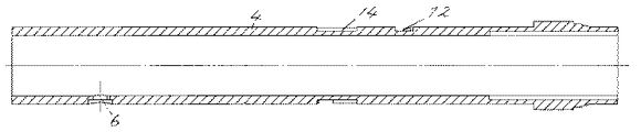
回転軸筒4の回転運動を行うには、ネジ式で行われるが、回転軸筒4の表面には駆動ネジ溝12を設け、該駆動ネジ溝12の終端(口金1側)には回転軸筒4の軸線に略直角の遊び溝13、軸方向のノック溝14を連設して細胴部3’の内側に突出する第一コマ8をスライド自在に嵌合して、胴部3とサヤ9の回転操作により行うようにし、ノック溝14と第一コマ8の前後操作は天冠11の押圧操作により行う。
The
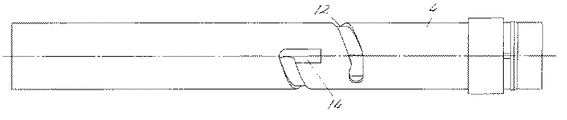
芯タンク5と取り付けケースの7の直線運動は以下のように行われる。即ち芯タンク5の前半部には、前記駆動ネジ溝12のピッチよりも大きいピッチの繰り出しネジ溝15と軸線と直角方向の遊び溝15’を連設して回転軸筒4に設けた第二コマ6を走行自在に嵌合してあり、芯タンク5の後半部における細タンク部5’には前記繰り出しネジ溝15と反対方向の後部繰り出しネジ溝16を同一ピッチで同回転の長さに設け、又芯タンク5の先端部は規制突条17になっていて胴部3先端内側に設けた溝18に嵌合して前後にのみ移動するようになっていて、芯タンク5を直線運動させるようになっており、更に後部繰り出し溝16に連続してピッチの狭い補助繰り出し溝16’が半周に亘って設けてあり、取り付けケース7の第三コマ19が走行するようにしてある。
The linear motion of the
芯タンク5の先端部には筆記具2としてのシャープペン機構が取り付けられており、胴部3とサヤ9の伸長時にはシャープペン2の芯先2’が口金の先端より露出し、筆記状態となり、芯が消耗することによりサヤ9を押すことにより第一コマ8がノック溝14に沿って移動し、それにしたがって芯タンク5が前進し、シャープペン2の芯を繰り出すようになっている。筆記具2がボールペンのペン場合はノック溝14を必要としない。
The tip of the
図1〜図10の実施例のものは、サヤ9の半回転(約180度)でサヤ9と胴部3を伸長状態とすると共に、この状態で補助具10としての消しゴムを天冠11より突出させないで筆記作業をし、且つ天冠11、サヤ9を押し作業を繰り返すことにより第一コマ8はノック溝14に沿って移動しシャープペン2の芯を繰り出すようにしたものであり、更にサヤ9を同方向に半回転することにより取り付けケース7のみを後方に移動させて先端に設けた補助具10(図では消しゴム)を天冠11の開口11’より突出させるようにしたものである。このとき、第2コマ6が遊び溝15’に位置し、第三コマ9が補助繰り出し溝16’に対応して取り付けケース7のみを天冠11方向に移動自するようになっている。
In the embodiment of FIGS. 1 to 10, the
図11〜図17は、サヤ9の一回転(約380度)でサヤ9と胴部3を伸長状態とすると共に、この状態で補助具10としての消しゴムを天冠11より突出させるようにしたもので、この状態で筆記作業をし、且つ消しゴム10、天冠11、サヤ9を押し作業を繰り返すことにより第一コマ8はノック溝14に沿って移動しシャープペン2の芯を繰り出すようにしたものである。
In FIGS. 11 to 17, the
以上のように駆動ネジ溝12、繰り出しネジ溝15、後部繰り出し溝16等のピッチ、長さは筆記具2と取り付けケース7の移動距離の相対関係において決めればよい。
As described above, the pitch and length of the driving
尚図の筆記具2はシャープペン機構のものを示してあるが、ボールペンでもよく、又補助具10としては消しゴムを示してあるが、そのほか修正液、色違いのその他の筆記具、口紅、チョークなどが考えられる。
The
本発明は以上のように構成されるもので、構造上の主要部である胴部3、回転軸筒4、芯タンク5、取り付けケース7は全て筒状態で、かつこれらの外側の一部にねじ加工を施すのみの簡単な作業でできるので歩留まりがよく、また組立作業も簡単であリ、又軸の両端よリ筆記具の芯先や消しゴム等の補助具を突出させて使用できるので筆記作業の効率化を図ることができる。
The present invention is configured as described above, and the
1:口金
2:筆記具
3:胴部
3’:後部細胴部
4:回転軸筒
5:芯タンク
6:第2コマ
7:取り付けケース
8:第一コマ
9:サヤ
10:補助具
11:天冠
12:駆動ネジ溝
13:遊び溝
14:ノック溝
15:繰り出しネジ溝
15’:遊び溝
16:後部繰り出しネジ溝
16’:補助繰り出し溝
17:規制突条
18:溝
19:第3コマ
1: base 2: writing instrument 3:
7: Mounting case 8: First frame 9: Saya 10: Auxiliary tool 11: Crown 12: Drive screw groove 13: Play groove 14: Knock groove 15: Feed screw groove 15 ': Play groove 16: Rear feed screw groove 16 ': Auxiliary payout groove 17: Restriction protrusion 18: Groove
19: Third frame
Claims (2)
Priority Applications (4)
| Application Number | Priority Date | Filing Date | Title |
|---|---|---|---|
| JP2004086457A JP3962389B2 (en) | 2004-03-24 | 2004-03-24 | Twisted telescopic writing instrument |
| TW093134897A TW200531849A (en) | 2004-03-24 | 2004-11-15 | Twist-type telescopic ball-point pen |
| CNA2004101016588A CN1672958A (en) | 2004-03-24 | 2004-12-20 | Twist-type telescopic ball-point pen |
| US11/030,529 US7329063B2 (en) | 2004-03-24 | 2005-01-05 | Twist-type telescopic ball-point pen |
Applications Claiming Priority (1)
| Application Number | Priority Date | Filing Date | Title |
|---|---|---|---|
| JP2004086457A JP3962389B2 (en) | 2004-03-24 | 2004-03-24 | Twisted telescopic writing instrument |
Publications (2)
| Publication Number | Publication Date |
|---|---|
| JP2005271348A JP2005271348A (en) | 2005-10-06 |
| JP3962389B2 true JP3962389B2 (en) | 2007-08-22 |
Family
ID=34990012
Family Applications (1)
| Application Number | Title | Priority Date | Filing Date |
|---|---|---|---|
| JP2004086457A Expired - Lifetime JP3962389B2 (en) | 2004-03-24 | 2004-03-24 | Twisted telescopic writing instrument |
Country Status (4)
| Country | Link |
|---|---|
| US (1) | US7329063B2 (en) |
| JP (1) | JP3962389B2 (en) |
| CN (1) | CN1672958A (en) |
| TW (1) | TW200531849A (en) |
Families Citing this family (19)
| Publication number | Priority date | Publication date | Assignee | Title |
|---|---|---|---|---|
| US20080056806A1 (en) * | 2006-09-05 | 2008-03-06 | Christopher Crawford | Mechanical Pencil with Battery Operated Spinning Eraser |
| CN101622138B (en) | 2007-02-26 | 2013-05-22 | 百乐墨水株式会社 | Thermally changeable color writing tool |
| KR101051971B1 (en) * | 2009-03-24 | 2011-07-26 | 주식회사 모리스 | Writing instruments at both ends simultaneously |
| US20120086664A1 (en) * | 2009-06-29 | 2012-04-12 | Gerald Leto | Multifunctional writing apparatus with capacitive touch screen stylus |
| US8480323B2 (en) * | 2010-04-30 | 2013-07-09 | A.T.X. International, Inc. | Expandable writing instrument |
| WO2012058530A2 (en) | 2010-10-28 | 2012-05-03 | Plastek Industries, Inc. | Applicators and assembly, filling, and dispensing methods |
| CN102133833A (en) * | 2011-01-23 | 2011-07-27 | 青岛昌隆文具有限公司 | Writing tool |
| US8734040B2 (en) | 2011-06-09 | 2014-05-27 | A.T.X. International, Inc. | Multi-function writing instrument with propulsion mechanism |
| US9550391B2 (en) * | 2011-11-18 | 2017-01-24 | Bic Corporation | Retractable writing instrument |
| US9086717B2 (en) * | 2012-02-13 | 2015-07-21 | Invicta Watch Company Of America, Inc. | Interface for actuating a device |
| US8967900B2 (en) | 2012-07-17 | 2015-03-03 | James M. Anderson | Hygienic writing instrument and method of using |
| JP6038570B2 (en) | 2012-09-24 | 2016-12-07 | 株式会社パイロットコーポレーション | Rotating operation writing instrument |
| CN102941758A (en) * | 2012-11-26 | 2013-02-27 | 张晓丹 | Pen capable of correcting bad habits |
| JP6249790B2 (en) * | 2013-01-29 | 2017-12-20 | 三菱鉛筆株式会社 | mechanical pencil |
| US10207534B2 (en) | 2013-03-15 | 2019-02-19 | Angelo P. Verdelli, Jr. | Writing implement holder |
| JP6038097B2 (en) * | 2014-10-30 | 2016-12-07 | 三菱鉛筆株式会社 | Writing instrument |
| EP3613605A1 (en) * | 2018-08-22 | 2020-02-26 | Société BIC | Writing instrument comprising a rotary eraser |
| JP2022530737A (en) * | 2019-04-30 | 2022-07-01 | ソシエテ ビック | Retractable elements for writing utensils |
| CN114987084A (en) * | 2021-03-01 | 2022-09-02 | 许可欣 | Pen capable of adapting to various refill lengths |
Family Cites Families (17)
| Publication number | Priority date | Publication date | Assignee | Title |
|---|---|---|---|---|
| US3597100A (en) | 1970-04-20 | 1971-08-03 | K C Pen Co Inc | Writing implement |
| US4601599A (en) | 1983-12-27 | 1986-07-22 | Katoh Kinzoku Kogyo Kabushiki Kaisha | Ball-point pen |
| JPS60199698A (en) | 1984-03-23 | 1985-10-09 | シヤチハタ工業株式会社 | Expansion type ball pen |
| JPS60199699A (en) | 1984-03-23 | 1985-10-09 | シヤチハタ工業株式会社 | Expansion type ball pen |
| JPS61202894A (en) | 1985-03-05 | 1986-09-08 | シヤチハタ工業株式会社 | Expansion type ball pen |
| JP2559469B2 (en) | 1988-07-11 | 1996-12-04 | 株式会社 日立ビルシステムサービス | Building remote monitoring device |
| JPH0427670A (en) | 1990-05-21 | 1992-01-30 | Toyota Motor Corp | Hydraulic reaction force type power steering control device |
| JP2509549B2 (en) | 1992-07-07 | 1996-06-19 | 株式会社イシダ | Sorting system |
| JPH0627433A (en) | 1992-07-10 | 1994-02-04 | Casio Comput Co Ltd | Stn type liquid crystal display device |
| JP3071038B2 (en) | 1992-07-22 | 2000-07-31 | 三洋電機株式会社 | Suction grill |
| ES2097961T3 (en) * | 1992-12-03 | 1997-04-16 | Kotobuki & Co Ltd | INSTRUMENT FOR WRITING. |
| JPH0732132A (en) | 1993-07-19 | 1995-02-03 | Kawasaki Heavy Ind Ltd | Method and device for assisting work in casting process |
| JPH10166783A (en) * | 1996-10-07 | 1998-06-23 | Kotobuki Kk | Double chuck type mechanical pencil |
| JP3040078B2 (en) | 1996-12-03 | 2000-05-08 | 加藤金属工業株式会社 | Telescopic ballpoint pen |
| JP3596607B2 (en) | 2001-02-09 | 2004-12-02 | 加藤金属工業株式会社 | Telescopic ballpoint pen |
| JP3665757B2 (en) | 2001-10-29 | 2005-06-29 | 加藤金属工業株式会社 | Telescopic ballpoint pen |
| US7018124B1 (en) * | 2004-10-20 | 2006-03-28 | Kotobuki & Co., Ltd. | Writing implement with stylus |
-
2004
- 2004-03-24 JP JP2004086457A patent/JP3962389B2/en not_active Expired - Lifetime
- 2004-11-15 TW TW093134897A patent/TW200531849A/en not_active IP Right Cessation
- 2004-12-20 CN CNA2004101016588A patent/CN1672958A/en active Pending
-
2005
- 2005-01-05 US US11/030,529 patent/US7329063B2/en not_active Expired - Fee Related
Also Published As
| Publication number | Publication date |
|---|---|
| JP2005271348A (en) | 2005-10-06 |
| US20050214057A1 (en) | 2005-09-29 |
| US7329063B2 (en) | 2008-02-12 |
| TW200531849A (en) | 2005-10-01 |
| TWI305517B (en) | 2009-01-21 |
| CN1672958A (en) | 2005-09-28 |
Similar Documents
| Publication | Publication Date | Title |
|---|---|---|
| JP3962389B2 (en) | Twisted telescopic writing instrument | |
| JP5373358B2 (en) | mechanical pencil | |
| JP2005111742A (en) | Telescopic ball-point pen | |
| JP4367858B2 (en) | Pay-out type ballpoint pen device | |
| JP2010036483A (en) | Writing instrument | |
| JP5373359B2 (en) | mechanical pencil | |
| JP3837916B2 (en) | Rear end knock writing instrument | |
| JP2558803Y2 (en) | Extension type eraser device | |
| JP2012061605A (en) | Duplex writing utensil | |
| JP4242860B2 (en) | Concealment type ballpoint pen | |
| JP2009061630A (en) | Shaft tube structure of writing tool | |
| JP2005053038A (en) | Rotational delivery type writing utensil | |
| JP3864542B2 (en) | Rear end knock writing instrument | |
| JP4373900B2 (en) | Writing instrument | |
| KR860003282Y1 (en) | Pencil case | |
| JPH0382600A (en) | Rotary protruding and withdrawing device of writing utensil and refill thereof | |
| JP2006248068A (en) | Penholder tube | |
| JP2607454Y2 (en) | Rod feeder | |
| JP2540964Y2 (en) | Stick-out container | |
| JP6047194B2 (en) | Writing instrument | |
| JP4559741B2 (en) | Knock-type writing instrument | |
| JPH088874Y2 (en) | Double-headed writing instrument with eraser | |
| JP2603322Y2 (en) | Composite writing instrument | |
| JPH0432303Y2 (en) | ||
| JP2566094Y2 (en) | Double writing instrument |
Legal Events
| Date | Code | Title | Description |
|---|---|---|---|
| A131 | Notification of reasons for refusal |
Free format text: JAPANESE INTERMEDIATE CODE: A131 Effective date: 20060907 |
|
| A521 | Request for written amendment filed |
Free format text: JAPANESE INTERMEDIATE CODE: A523 Effective date: 20061107 |
|
| TRDD | Decision of grant or rejection written | ||
| A01 | Written decision to grant a patent or to grant a registration (utility model) |
Free format text: JAPANESE INTERMEDIATE CODE: A01 Effective date: 20070402 |
|
| A61 | First payment of annual fees (during grant procedure) |
Free format text: JAPANESE INTERMEDIATE CODE: A61 Effective date: 20070518 |
|
| R150 | Certificate of patent or registration of utility model |
Ref document number: 3962389 Country of ref document: JP Free format text: JAPANESE INTERMEDIATE CODE: R150 Free format text: JAPANESE INTERMEDIATE CODE: R150 |
|
| FPAY | Renewal fee payment (event date is renewal date of database) |
Free format text: PAYMENT UNTIL: 20100525 Year of fee payment: 3 |
|
| FPAY | Renewal fee payment (event date is renewal date of database) |
Free format text: PAYMENT UNTIL: 20110525 Year of fee payment: 4 |
|
| R250 | Receipt of annual fees |
Free format text: JAPANESE INTERMEDIATE CODE: R250 |
|
| R250 | Receipt of annual fees |
Free format text: JAPANESE INTERMEDIATE CODE: R250 |
|
| FPAY | Renewal fee payment (event date is renewal date of database) |
Free format text: PAYMENT UNTIL: 20130525 Year of fee payment: 6 |
|
| R250 | Receipt of annual fees |
Free format text: JAPANESE INTERMEDIATE CODE: R250 |
|
| FPAY | Renewal fee payment (event date is renewal date of database) |
Free format text: PAYMENT UNTIL: 20140525 Year of fee payment: 7 |
|
| R250 | Receipt of annual fees |
Free format text: JAPANESE INTERMEDIATE CODE: R250 |
|
| R250 | Receipt of annual fees |
Free format text: JAPANESE INTERMEDIATE CODE: R250 |
|
| R250 | Receipt of annual fees |
Free format text: JAPANESE INTERMEDIATE CODE: R250 |
|
| R250 | Receipt of annual fees |
Free format text: JAPANESE INTERMEDIATE CODE: R250 |
|
| R250 | Receipt of annual fees |
Free format text: JAPANESE INTERMEDIATE CODE: R250 |
|
| R250 | Receipt of annual fees |
Free format text: JAPANESE INTERMEDIATE CODE: R250 |
|
| R250 | Receipt of annual fees |
Free format text: JAPANESE INTERMEDIATE CODE: R250 |
|
| R250 | Receipt of annual fees |
Free format text: JAPANESE INTERMEDIATE CODE: R250 |
|
| R250 | Receipt of annual fees |
Free format text: JAPANESE INTERMEDIATE CODE: R250 |
|
| R250 | Receipt of annual fees |
Free format text: JAPANESE INTERMEDIATE CODE: R250 |
|
| R250 | Receipt of annual fees |
Free format text: JAPANESE INTERMEDIATE CODE: R250 |