JP3961908B2 - Seismic isolation device - Google Patents

Seismic isolation device Download PDF

Info

Publication number
JP3961908B2
JP3961908B2 JP2002247021A JP2002247021A JP3961908B2 JP 3961908 B2 JP3961908 B2 JP 3961908B2 JP 2002247021 A JP2002247021 A JP 2002247021A JP 2002247021 A JP2002247021 A JP 2002247021A JP 3961908 B2 JP3961908 B2 JP 3961908B2
Authority
JP
Japan
Prior art keywords
support
seismic isolation
intermediate support
isolation device
lower support
Prior art date
Legal status (The legal status is an assumption and is not a legal conclusion. Google has not performed a legal analysis and makes no representation as to the accuracy of the status listed.)
Expired - Fee Related
Application number
JP2002247021A
Other languages
Japanese (ja)
Other versions
JP2004084313A (en
Inventor
健一 川口
憲昭 松本
嘉之 江良
啓一 阿部
純一郎 阿部
徹 古川
朝康 田口
Current Assignee (The listed assignees may be inaccurate. Google has not performed a legal analysis and makes no representation or warranty as to the accuracy of the list.)
Individual
Original Assignee
Individual
Priority date (The priority date is an assumption and is not a legal conclusion. Google has not performed a legal analysis and makes no representation as to the accuracy of the date listed.)
Filing date
Publication date
Application filed by Individual filed Critical Individual
Priority to JP2002247021A priority Critical patent/JP3961908B2/en
Publication of JP2004084313A publication Critical patent/JP2004084313A/en
Application granted granted Critical
Publication of JP3961908B2 publication Critical patent/JP3961908B2/en
Anticipated expiration legal-status Critical
Expired - Fee Related legal-status Critical Current

Links

Images

Landscapes

  • Buildings Adapted To Withstand Abnormal External Influences (AREA)
  • Vibration Prevention Devices (AREA)

Description

【0001】
【発明の属する技術分野】
本発明は、建物の躯体側と基礎コンクリート等の地盤側と間を絶縁して、地震等の外力から建物を保護する免震装置に関する。
【0002】
【従来の技術】
建物の免震装置に関しては、従来から種々の形式のものが知られている。例えば、積層ゴムを使用する形式のもの、転がり支承を使用する形式のもの、滑り支承を使用する形式のものなど、種々の形式のものが知られている(特許庁編特許マップシリーズ「耐震・免震・制震構造、装置」平成12年7月25日社団法人発明協会発行)。ところで、免震装置には対応できる水平方向の変位の範囲、すなわち当該免震装置として許容される動作範囲が存在し、この動作範囲を大きくとるには装置の規模を大きくする必要があり、設置コストが割高になったり設置スペースが大きくとられるといった問題がある。前記従来技術における種々の形式の免震装置においても、この点に関する的確な解決は得られていない。
【0003】
【発明が解決しようとする課題】
本発明は、以上のような従来技術の状況に鑑みて開発したものであり、装置の大きさの割に動作範囲を大きくとることができ、大きな振幅に対する絶縁機能を有するとともに、その絶縁機能に加えて、元の設置状態に戻る機能(復帰機能)や地震作用が所定値を超えた場合に動作を開始する機能(トリガ機能)を付加したり、動作範囲を規制したりするなどの設定の自由度も大きい免震装置を提供することを目的とする。
【0004】
【課題を解決するための手段】
前記課題を解決するため、請求項1の発明では、少なくとも躯体側又は地盤側に対していずれの方向にも傾斜し得るように回動自在に支持された支軸に遊嵌することにより、躯体側の特定点と地盤側の特定点とを結ぶ軸線上に変位する前記支軸に対して相対移動可能に設けられた盤状部を有する中間支持体と、該中間支持体と躯体側との間に配設された上部支持体と、前記中間支持体と地盤側との間に配設された下部支持体とを備え、それらの上部支持体及び下部支持体の少なくとも一方を前記中間支持体の盤状部に形成した支持面に相対移動可能に接触させるという技術手段を採用した。本発明によれば、免震装置としての大きさの割に躯体側と地盤側との大きな相対的変位に対応できる点で特徴を有する。すなわち、装置の規模の割に大きな相対的変位に対して絶縁機能を発揮することが可能である。
【0005】
請求項2の発明では、少なくとも躯体側又は地盤側に対していずれの方向にも傾斜し得るように回動自在に支持された支軸に遊嵌することにより、躯体側の特定点と地盤側の特定点とを結ぶ軸線上に変位する前記支軸に対して相対移動可能に設けられた筒状部を有する中間支持体と、該中間支持体と躯体側との間に配設された上部支持体と、前記中間支持体と地盤側との間に配設された下部支持体とを備え、それらの上部支持体及び下部支持体の少なくとも一方に形成した支持面に前記中間支持体の筒状部を相対移動可能に接触させるという技術手段を採用した。本発明は、相対移動可能に支持する支持面を、請求項1の発明では中間支持体側に形成したのに対して、上部支持体ないし下部支持体側に形成した点で特徴を有するものであり、請求項1の発明と基本的に同様の機能を奏する。
【0006】
請求項3の発明では、前記中間支持体を、躯体側に回動自在に支持された上部支軸及び地盤側に回動自在に支持された下部支軸に対して、それらの軸線に沿って相対移動し得るように遊嵌するようにした。また、請求項4の発明では、前記中間支持体に地盤側に回動自在に支持された支軸を貫通させ、中間支持体を支軸の軸線に沿って相対移動可能に遊嵌するとともに、前記支軸の他側を躯体側に配設した自在支持部を貫通させて回動自在に支持するようにした。すなわち、請求項3の発明では、上部支軸と下部支軸の上下に分れた支軸を用いて中間支持体を相対移動可能に遊嵌したのに対して、請求項4の発明では、1本の長尺の支軸を用いた点で相違している。なお、前記中間支持体と前記支軸との間は、例えばキー結合やスプライン結合あるいは断面矩形状の支軸及び遊嵌孔の採用等により、支軸の軸線方向にのみ相対移動可能に遊嵌し、相対回転運動は阻止するように構成してもよい(請求項5)。
【0007】
請求項6の発明では、請求項1の発明に関して、前記上部支持体を前記中間支持体の盤状部の上部支持面に対して相対移動可能に接触させるとともに、前記下部支持体を前記中間支持体の盤状部の下部支持面に対して相対移動可能に接触させるという技術手段を採用した。また、請求項7の発明では、前記上部支持体が相対移動可能に接触する前記中間支持体の盤状部の上部支持面及び/又は前記下部支持体が相対移動可能に接触する前記中間支持体の盤状部の下部支持面の縦断面形状として、その盤状部の中央部から放射方向に凹状の曲面を採用した。
【0008】
請求項8の発明では、前記躯体側の特定点と地盤側の特定点との間の水平方向の相対移動距離に関係なく、前記上部支持体と前記中間支持体側との接触部と、前記下部支持体と前記中間支持体側との接触部との間の上下方向の間隔が常に一定になるように設定した。本発明は、復帰手段が別途設置される場合に好適な復帰機能を有しない形式の免震装置に関する。請求項9の発明では、前記躯体側の特定点と地盤側の特定点との間の水平方向の相対移動距離が大きくなるにつれて、前記上部支持体と前記中間支持体側との接触部と、前記下部支持体と前記中間支持体側との接触部との間の上下方向の間隔が大きくなるように設定した。本発明によれば、水平方向の相対移動距離に応じて躯体側が上昇して位置のエネルギが増加することから、位置のエネルギが減少する相対的変位の小さい方向へ復帰する復帰機能の付加が可能である。
【0009】
請求項10の発明では、前記躯体側の特定点と地盤側の特定点との間に水平方向のズレのない状態において、前記上部支持体及び/又は下部支持体と前記中間支持体が円周上で接触するように構成した。本発明によれば、前記躯体側の特定点と地盤側の特定点との間に水平方向のズレのない状態において、前記上部支持体及び/又は下部支持体と前記中間支持体が円周上で線接触して安定した状態にあることから、前記躯体側の特定点と地盤側の特定点との間の水平方向の相対移動の開始を地震が所定規模以上の場合に抑制するトリガ機能の付加が可能である。すなわち、ここでは少なくとも円周上の線接触による摩擦作用に基づく安定性を活用して、小規模の地震に対しては、水平動作を開始しないように構成した。請求項11の発明では、前記中間支持体の前記上部支持体及び/又は下部支持体との接触部に、それらの間の相対移動の範囲を規制する動作規制部を設けるという技術手段を採用し、請求項12の発明では、前記躯体側に回動自在に支持された上部支軸と地盤側に回動自在に支持された下部支軸との間に、それらの上部支軸と下部支軸との間の相対移動を抑制する手段を付加するという技術手段を採用した。
【0010】
【発明の実施の形態】
本発明に係る免震装置は、各種の建物の免震装置として広く適用することが可能である。前記中間支持体、上部支持体あるいは下部支持体の具体的構成や、それらの間の具体的な関連構成に関しては種々の形態が可能である。基本的な形態としては、中間支持体と上部支持体ないし下部支持体との間の相対移動を可能にする支持面を請求項1の発明のように中間支持体側に設ける形態と、請求項2の発明のように上部支持体ないし下部支持体側に設ける形態とがある。本発明の基本的な機能を得るには、前記上部支持体及び下部支持体の少なくとも一方を中間支持体と相対移動可能に接触させればよい。後述の各実施例のように、上部支持体及び下部支持体の双方を中間支持体に対して相対移動可能に接触させる形態を採用してもよいし、あるいは第10実施例のように下部支持体のみを中間支持体に対して相対移動可能に接触させるか、逆に上部支持体のみを中間支持体に対して相対移動可能に接触させる形態を採用することも可能である。その選択に応じて、中間支持体や上部支持体あるいは下部支持体の具体的構成も変化することになる。因みに、本発明に係る複数台の免震装置を上下方向に重ねて設置する形態も可能である。
【0011】
前記中間支持体の盤状部に支持面を形成する形態に関しては、後述の各実施例で例示したように盤状部の中央部から放射状に凹状の曲面に形成したものが好例であるが、必ずしもこれに限定されるわけではない。平面からなるものでもよいし、凸状の曲面からなるものでもよい。また、上部支持体あるいは下部支持体と接触する可能性のある盤状部全体の放射方向の形状が曲面だけで形成される必要性はなく、途中に直線的な部分が混在してもよい。支持面の具体的形状に関しては、その支持面を中間支持体側に設置するか、あるいは上下の支持体側に設置するかに関わらず、上部支持体側との接触部と下部支持体側との接触部との間の上下方向の間隔が常に一定になる復帰機能を有しない形態に設定することも可能であるし、躯体側と地盤側との間の水平方向の相対移動距離に応じて前記間隔が増加する復帰機能を有する形態に設定することも可能である。また、その間隔の増加率の設定により復帰特性を調整することも可能である。さらに、後述の実施例のように、トリガ機能や動作範囲の規制に適した形状を取込むことも可能である。以上のように、中間支持体の盤状部あるいは上部支持体ないし下部支持体に形成する支持面の形状により、種々の特性を有する形態を容易に設定し得るところにも本発明の特徴が存在する。
【0012】
前記中間支持体は、その中心部に形成した中央孔を、躯体側に対していずれの方向にも傾斜し得るように回動自在に支持された上部支軸及び地盤側に対していずれの方向にも傾斜し得るように回動自在に支持された下部支軸に遊嵌することにより、それらの支軸の軸線に沿って相対移動可能に組付けることが可能である。その場合に、それらの上部支軸と下部支軸の先端部間をゴム等の弾性材等からなる伸縮材にて連結し、適度の初期張力を付加してトリガ機能を付加したり、復帰特性や減衰特性を向上することも可能である。なお、中間支持体の中央孔と各支軸との遊嵌状態における両者間の摩擦作用を減衰機能に活用することも可能である。また、前記上部支軸と下部支軸の先端部間に油圧ダンパや空圧ダンパ等の流体圧ダンパ手段を組込み、その減衰特性を調整することにより、免震装置としてのトリガ機能や減衰機能を付加することも可能である。さらに、前記上部支軸と下部支軸の先端部間をワイヤ等で連結することにより、免震装置としての動作範囲を規制することも可能である。以上のように、上部支軸と下部支軸の先端部間に設置する連結手段により種々の機能を付加し得るところにも本発明の特徴が存在する。なお、場合に応じて、上述の各形態を選定して組合わせ構成することが可能なことはいうまでもない。因みに、後述の第9実施例及び第12実施例のように、中間支持体を移動可能に貫通支持する支軸として1本からなる長尺の支軸を使用し、その支軸の下端部を下部支持体に設けた自在支持部を介して回動自在に支持するとともに、他側を上部支持体に設けた自在支持部を移動可能に貫通させて上方へ突出させ、前記自在支持部おいて回動自在に支持した形態も可能である。
【0013】
【実施例】
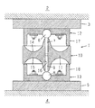
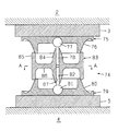
図1は本発明に係る第1実施例の設置状態を示した縦断面図である。図示のように、本発明に係る免震装置1は、躯体側2に設置した座板3と基礎コンクリート等の地盤側4に設置した座板5との間に設置される。本実施例では、免震装置1が、躯体側2に球面自在軸受け等の自在支持部6を介してあらゆる方向に傾斜し得るように回動自在に支持した上部支軸7と同様に地盤側4に自在支持部8を介して回動自在に支持した下部支軸9とを結ぶ軸線に沿って相対移動可能に設けた中間支持体10と、この中間支持体10の盤状部11の上面と躯体側2との間に配設した上部支持体12と、中間支持体10の盤状部11の下面と地盤側4との間に配設した下部支持体13とから構成される場合を示した。図1は躯体側2の特定点としての自在支持部6と地盤側4の特定点としての自在支持部8との間に水平方向のズレがない平常状態における設置状態を示したものである。
【0014】
本実施例では、前記中間支持体10の盤状部11の上下面に形成した上部支持面14及び下部支持面15は、図示のようにその盤状部11の中央部から放射状に凹状の曲面になるように形成した。また、中間支持体10の中心部に形成した中央孔部16に上部支軸7と下部支軸9の自由端側を移動可能に遊嵌するように構成した。上部支持体12及び下部支持体13は、有底の低い円筒状に形成し、それらの底部をそれぞれ座板3,5に対して植込みボルトとナットを用いて固定した。それらの上部支持体12及び下部支持体13の筒状部17,18の端部は、中間支持体10の盤状部11の上下面に形成した上部支持面14及び下部支持面15に相対移動可能に接触させ、それらの接触を介して躯体側2の荷重を上部支持体12、中間支持体10、下部支持体13へ順次伝達して地盤側4によって支持するように構成した。なお、上部支持体12及び下部支持体13の筒状部17,18の端部は、上部支持面14あるいは下部支持面15との間の相対移動の円滑性のために円弧状断面が好適であるが、他の断面形状のものでもよい。さらに、その筒状部17,18の端部に相対移動の円滑性を改善するための滑り材や鋼製ボールないし小さいベアリング等を付設してもよいし、両支持面14,15を自己潤滑材料で構成したりメッキを施したりしてもよい。また、それらの接触部に潤滑油や防錆材を供給するようにしたり、摩擦低減材を塗布したり、貼付したり、含浸させたりしてもよい。さらに、中間支持体10の周囲をジャバラ等の防塵用のカバー材により外部と遮断するようにしてもよい。
【0015】
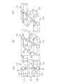
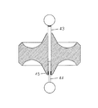
図2は前記第1実施例の要部の挙動を示した動作説明図である。状態(A)は、躯体側2と地盤側4との間に水平方向のズレがない平常状態を示したものであり、図示のように、上部支持体12の筒状部17の下端部が中間支持体10の盤状部11の上部支持面14の周辺部の円周上に線接触するとともに、下部支持体13の筒状部18の上端部が前記盤状部11の下部支持面15の周辺部の円周上に線接触した状態で安定的に停止している。この状態では、躯体側の荷重は、それらの円周上の線接触を介して上部支持体12、中間支持体10、下部支持体13へと順次伝達され、地盤側によって支持されている。
【0016】
しかして、地震等の外力が作用し、その水平方向成分により躯体側2と地盤側4との間に水平方向の相対的な変位が生じると、状態(B)に示したように上部支軸7と下部支軸9が中央孔部16内を相対移動しながら、自在支持部6,8を中心に回動して傾斜する。すなわち、図示のように、上部支軸7と下部支軸9が特定点としての自在支持部6,8を結ぶ軸線上に変位する。この上部支軸7と下部支軸9の傾斜に伴って中間支持体10も傾斜し、上部支持体12及び下部支持体13の筒状部17,18の端部と中間支持体10の盤状部11の上部支持面14ないし下部支持面15との接触部が移動して、躯体側2の荷重を支持しながら地盤側4との相対的な変位を吸収することになる。そして、躯体側2と地盤側4との間の相対的な変位が更に大きくなると、状態(C)に示したように、より大きな傾斜状態に移行することになる。また、躯体側2と地盤側4との間の相対的な変位が縮小すれば、逆に辿って傾斜角が縮小する方向に移行することになる。なお、上部支軸7及び下部支軸9と中間支持体10の中央孔部16との案内支持関係を長く設定しておけば、理論的には状態(C)から更に相対変位が増えた場合にも対応することができる。
【0017】
なお、本実施例では、図示のように、状態(A)から状態(B)、状態(C)へと移行しても、上部支持体12の筒状部17の下端部と上部支持面14との接触部と、下部支持体13の筒状部18の上端部と下部支持面15との接触部の間の間隔Saが常に一定になるように両支持面14,15の形状を設定した場合を示した。これにより、本実施例では、自在支持部6は水平の軌道Aを辿り、躯体側2と地盤側4との間の水平方向の相対移動距離に関係なく、上部支持体12の上面と下部支持体13の下面との間の上下方向の間隔St、すなわち躯体側2と地盤側4との間の支持間隔が常に一定になる。因みに、本実施例の場合には、復帰機能を有していないことから、復帰手段を別に設ける必要がある。なお、地震エネルギ等の外部エネルギは、主として上部支持体12及び下部支持体13の筒状部17,18の端部と中間支持体10の盤状部11に形成した上部支持面14ないし下部支持面15との接触部における摩擦により減衰されることになる。
【0018】
図3は本発明に係る第2実施例の要部の挙動を示した動作説明図である。なお、以下の説明では、前記第1実施例と共通している構成部分には同じ符号を使用して説明する。本実施例は、前記第1実施例に復帰機能を付加した点で特徴を有する。その復帰機能の付加のため、本実施例では、平常状態の状態(A)から状態(B)、更に状態(C)へ移行するにつれて、自在支持部6が軌道Bで示したように徐々に上昇するように、中間支持体19の盤状部20の上下面に形成した凹状曲面からなる上部支持面21及び下部支持面22の具体的形状を設定した。すなわち、上部支持体12の筒状部17の下端部と上部支持面21との接触部と、下部支持体13の筒状部18の上端部と下部支持面22との接触部の間の間隔Sbが、状態(A)から状態(B)、更に状態(C)へ移行するにつれて徐々に増加するように、前記上部支持面21及び下部支持面22の具体的形状を設定した。これにより、本実施例の場合には、状態(A)から状態(B)、更に状態(C)へ移行するにつれて、上部支持体12と共に躯体側2が徐々に上昇して位置のエネルギを蓄えることになる。したがって、位置のエネルギが減少する状態(A)側への復帰機能が付加されることになる。その具体的な復帰特性は、前記間隔Sbの変化率の設定を介して調整することができる。
【0019】
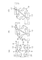
図4は本発明に係る第3実施例の要部の挙動を示した動作説明図である。本実施例は、前記第1実施例にトリガ機能を付加した点で特徴を有する。図示のように、本実施例では、状態(A)で示した平常状態において、上部支持体12の筒状部17の下端部が中間支持体23の盤状部24の上面に形成した凹状曲面からなる上部支持面25の周辺部に線接触するとともに、下部支持体13の筒状部18の上端部が前記盤状部24の下面に形成した凹状曲面からなる下部支持面26の周辺部に線接触した状態で安定的に停止している。図5の部分拡大図で示したように、上部支持面25及び下部支持面26の周辺部には、トリガ機能を奏する小さな平坦面からなるトリガ当接部27,28を形成している。なお、それらのトリガ当接部27,28としては、当接状態の安定性や動作の円滑性の観点から平坦面が適しているが、他の形状も可能である。因みに、本実施例では、躯体側2と地盤側4との間の相対的移動の開始時にトリガ当接部27,28を介して躯体側2が上昇するように構成し、その躯体側2の上昇に伴う強力な対抗力よりトリガ機能を奏する場合を例示したが、円周上の線接触による摩擦のみに基づく安定性を活用した、躯体側2の上昇を伴わない形態によってもトリガ機能を奏することは可能である。また、中間支持体23の中央の支軸遊嵌部の下端部と下部支持体13側の適宜部位との間及び/又は中間支持体23の中央の支軸遊嵌部の上端部と上部支持体12側の適宜部位との間にスプリング等の適宜の弾性手段を介在させて、トリガ当接部27,28に作用する荷重の度合を調整することによりトリガ機能を調整し得るように構成することも可能である。
【0020】
しかして、本実施例において地震等の外力が作用した場合には、平常状態の状態(A)から状態(B)へ移行する際に、上部支持体12の筒状部17の下端部及び下部支持体13の筒状部18の上端部と、中間支持体23の盤状部24の上下面に形成した上部支持面25及び下部支持面26の周辺部に形成したトリガ当接部27,28との接触部の軌跡との関係から、自在支持部6は軌道Cを辿ることから、状態(B)へ移行するには上部支持体12と共に躯体側2を持上げる必要がある。すなわち、平常状態の状態(A)から状態(B)への移動開始時に、その移動を抑制するかなり強力なトリガ機能が作用することになる。状態(B)に至った後は、前記第1実施例の場合と同様の動作過程を経て状態(C)へ移行する。なお、以上では、第1実施例にトリガ機能を付加した場合を示したが、第2実施例に適用することにより、復帰機能とトリガ機能を付加し得ることはいうまでもない。
【0021】
図6は本発明に係る第4実施例の要部の挙動を示した動作説明図である。本実施例は、免震装置としての動作範囲を規制する動作規制部を付加した点で特徴を有する。図示のように、本実施例では、中間支持体29の盤状部30の上下面に形成した凹状曲面からなる上部支持面31及び下部支持面32の中央部側に形成した係止段部33,34により動作範囲を規制するように構成した。すなわち、地震等の外力が作用し、状態(A)から状態(B)を経て状態(C)の状態に至った場合には、上部支持体12の筒状部17の下端部及び下部支持体13の筒状部18の上端部が係止段部33,34に係止して動作範囲を規制する。
【0022】
図7は本発明に係る第5実施例の要部の挙動を示した動作説明図である。本実施例は、第4実施例と同様に免震装置としての動作範囲を規制する動作規制部を付加した点で特徴を有する。図示のように、本実施例では、中間支持体35の盤状部36の上下面に形成した凹状曲面からなる上部支持面37及び下部支持面38の中央部側に規制用傾斜部39,40を設けて動作範囲を規制するように構成した。本実施例の場合には、地震等の外力が作用し、状態(A)から状態(B)を経て状態(C)の状態に至ると、上部支持体12の筒状部17の下端部及び下部支持体13の筒状部18の上端部が前記規制用傾斜部39,40に係合し、それ以後の上部支持体12と下部支持体13との相対移動には躯体側2の上昇が伴うことになる。この躯体側2の上昇にはより大きな水平方向の外力が必要なことから、逆に上部支持体12と下部支持体13との相対移動が抑制されて動作範囲が規制されることになる。なお、本実施例では動作範囲の規制手段として規制用傾斜部39,40を採用しているので、前記係止段部33,34に比べて規制作用が緩やかである。
【0023】
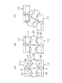
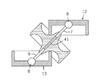
図8は本発明に係る第6実施例の要部を示した縦断面図である。本実施例の場合も、免震装置としての動作範囲を規制する動作規制部を付加した点で特徴を有する。図示のように、本実施例では、躯体側2に回動自在に支持された上部支軸7と地盤側4に回動自在に支持された下部支軸9との間をワイヤ41等によって連結することにより、それらの上部支軸7と下部支軸9との間の相対移動を所定の範囲に制限するという技術手段を採用した。すなわち、図示のようにワイヤ41が張った時点で、免震装置としての動作が規制されることになる。なお、以上の第4実施例から第6実施例の動作規制手段を複数採用して同時に設置することも可能である。
【0024】
図9は本発明に係る第7実施例の要部を示した縦断面図である。本実施例は、躯体側2に回動自在に支持された上部支軸7と地盤側4に回動自在に支持された下部支軸9との間に、それらの上部支軸7と下部支軸9との間の相対移動を抑制する手段を付加した点で特徴を有する。図示のように、本実施例では、上部支軸7と下部支軸9との間の相対移動を抑制する手段として、それらの上部支軸7と下部支軸9との間をゴム等の弾性材などからなる減衰機能を有する伸縮材42を用いて連結するという技術手段を採用した。しかして、地震等の外力が作用して状態(A)から状態(B)に移行する場合には伸縮材42の伸長を伴うことから、その伸縮材42に適度の初期張力を付加してトリガ機能を付加したり、復帰特性や減衰特性を向上したりすることが可能である。
【0025】
図10は本発明に係る第8実施例の要部を示した縦断面図である。本実施例は、躯体側2に回動自在に支持された上部支軸43と地盤側4に回動自在に支持された下部支軸44との間に、それらの相対移動を抑制する手段を付加した点で特徴を有する。図示のように、本実施例では、上部支軸43と下部支軸44との間の相対移動を抑制する手段として、それらの上部支軸43と下部支軸44との間に油圧ダンパないし空圧ダンパからなる従来の流体圧ダンパ手段を組込み、例えば上部支軸43内に設置する図示しない絞り部を流通する際の流体抵抗により減衰機能を付加するというダンパ技術を採用した。しかして、地震等の外力が作用した場合には、上部支軸43と下部支軸44が傾斜して、それらの間に相対的な移動が生じることになるが、その際には前記流体圧ダンパ手段の減衰機能が作用する。したがって、その流体圧ダンパ手段の減衰特性を適当に調整することにより、免震装置としてのトリガ機能や減衰機能を付加することができる。さらに、上部支軸43と下部支軸44との自由端側の嵌合部をテーパ状の外面と内面に形成して注油した状態で遊嵌することにより、その間の相対移動を抑制したり、移動範囲を規制したりすることも可能である。なお、図中45は防塵機能を有する軸受部である。
【0026】
図11は本発明に係る第9実施例の要部を示した縦断面図である。本実施例は前記第1実施例の変形例である。本実施例に係る免震装置46は、中間支持体47を移動可能に貫通支持する支軸として1本からなる長尺の支軸48を使用した点に特徴がある。支軸48の下端部は、下部支持体49に設けた球面自在軸受け等の自在支持部50を介してあらゆる方向に傾斜し得るように回動自在に支持している。また、支軸48の他側は、上部支持体51に設けた自在支持部52を移動可能に貫通して上方に突出した状態にあり、前記自在支持部52おいて回動自在に支持されている。そして、自在支持部52から突出した支軸48の上部は、上部支持体51に形成した開口部53、上部座板54に形成した開口部55及び躯体側2に形成した開口部56を介して上方に延びた状態に設置される。因みに、本実施例に係る免震装置46の地震時における免震動作に関しては、前記第1実施例と基本的に異なるところはなく、同様の挙動を示す。
【0027】
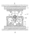
図12は本発明に係る第10実施例の要部を示した縦断面図であり、図13はその要部の挙動を示した動作説明図である。本実施例に係る免震装置は、上述の各実施例が上部支持体12及び下部支持体13を共に中間支持体の盤状部の上下面に形成した上部支持面あるいは下部支持面に相対移動可能に接触させた形態を採用しているのに対して、下部支持体のみを中間支持体の盤状部の下部支持面に対して相対移動可能に接触させる形態を採用した点で大きな特徴を有する。図12に示したように、本実施例に係る免震装置57は、躯体側2に設置した座板3に固定される上板58と該上板58に固着された支軸体59とその先端部に設置された球状部60からなる上部支持体61と、前記球状部60に対してあらゆる方向に傾斜し得るように回動自在に嵌合する嵌合凹部62を有し、盤状部63の下面を放射方向に凹状の曲面に形成して下部支持面64を形成するとともに、中心部に中央孔65を形成した中間支持体66と、有底筒状からなり、底部67を介して基礎コンクリート等の地盤側4に設置した座板5に固着されるとともに、その底部67の上面中央部に、前記中間支持体66の中央孔65に相対移動可能に挿入される下部支軸68の下端部を球面自在軸受け等の自在支持部69を介してあらゆる方向に傾斜し得るように回動自在に支持し、筒状部70の上端部を前記中間支持体66の盤状部63の下面に形成した下部支持面64に相対移動可能に接触させた下部支持体71とから構成した。なお、前記支軸体59に関しては、上方がより大径からなるテーパ状等に形成することも可能である。さらに、本実施例では、前記球状部60の下部に円錐状の嵌合凹部72を形成するとともに、下部支軸68の先端部にその嵌合凹部72に嵌合し得る円錐状の嵌合凸部73を形成し、平常の設置状態において、それらの嵌合凹部72と嵌合凸部73とを嵌合させることにより、トリガ機能を付加するように構成している。
【0028】
しかして、地震等の外力が作用した場合には、図13に示したように、状態(A)で示した平常の設置状態から、上部支持体61と下部支持体71との相対変位量に応じて、状態(B)、状態(C)へと移行することになる。状態(A)から状態(B)への移行の際には、前記球状部60の下部に形成した嵌合凹部72と下部支軸68の先端部に形成した嵌合凸部73を嵌合状態から脱出させる必要があるため、これがトリガ手段として機能する。しかる後は、下部支持体71の筒状部70の上端部が中間支持体66の盤状部63の下面に形成した凹状曲面からなる下部支持面64と接触しながら相対移動することにより、前述の実施例と同様に、躯体側2と地盤側4との間の絶縁機能を奏することになる。因みに、本実施例の場合には、上部支持体61が中間支持体66と一体的に動作するため、吸収し得る水平方向の相対変位量は、前述の実施例の半分になる。なお、図13に示した実施例においては、水平方向の相対変位に対して上板58の上面と下部支持体71の底部67の下面との間の間隔が一定の復帰機能を有しない場合を例示したが、前述の実施例の場合と同様に、中間支持体66の盤状部63の下面に形成する凹状曲面からなる下部支持面64の具体的形状に関する設定の仕方により、水平方向の相対変位に応じて上板58の上面と下部支持体71の底部67の下面との間の間隔が増えるように設定することにより、復帰機能を付加することも可能である。その他、前述の各実施例で説明した技術手段は、必要に応じて本実施例に適用することも可能である。
【0029】
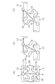
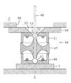
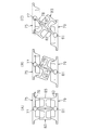
次に、図14〜図18を用いて他の形態の実施例に関して説明する。図14は本発明に係る第11実施例の要部を示した縦断面図である。図示のように、本発明に係る免震装置74は、前述の各実施例と同様に、躯体側2に設置した座板3と基礎コンクリート等の地盤側4に設置した座板5との間に設置される。本実施例では、座板3を挟んで躯体側2に固定した上部支持体75の下面周辺部に上部支持面76を形成するとともに、下面中央部に球面自在軸受け等からなる自在支持部77を配設し、その自在支持部77を介して上部支軸78をあらゆる方向に傾斜し得るように回動自在に支持した。また、座板5を挟んで地盤側4に固定した下部支持体79の上面周辺部に下部支持面80を形成するとともに、上面中央部に球面自在軸受け等からなる自在支持部81を配設し、その自在支持部81を介して上部支軸82をあらゆる方向に傾斜し得るように回動自在に支持した。図示のように、それらの上部支持体75と下部支持体79との間には、中間支持体83が配設される。この中間支持体83は、中央に位置する支軸嵌合部84と、周辺部に位置する筒状部85と、それらの支軸嵌合部84と筒状部85とを連結する連結板部86とから構成される。前記上部支軸78と下部支軸82は、支軸嵌合部84に形成した中央孔部87に上下から遊嵌され、中間支持体83を自在支持部77,81を結ぶ軸線に沿って相対移動可能に支持する。また、中間支持体83の筒状部85は、その上端部を上部支持体75の下面周辺部に形成した上部支持面76に当接するとともに、下端部を下部支持体79の上面周辺部に形成した下部支持面80に当接するとにより、上部支持体75に作用する躯体側2の荷重を下部支持体79を介して地盤側4に伝達するように構成されている。なお、前述のように、前記上部支軸78ないし下部支軸82と中央孔部87との嵌合状態に関しては、軸線方向の移動のみを許容し、相対的な回転は阻止するように構成してもよい。
【0030】
図15は中間支持体に関する実施例を示した横断面図である。図中、実施例Aとして示した形状は、図14に示した第11実施例に使用した中間支持体83のA−A断面を示したものである。図示のように、この中間支持体の横断面形状に関しては、実施例B〜Eに例示したように、支軸嵌合部84と筒状部85とを、前記連結板部86に替えて、適宜数の連結片部88にて連結するように構成することにより、それらの連結片部88相互間に空間部89を形成し、材料の削減や軽量化を図ることも可能である。
【0031】
図16は前記第11実施例の要部の挙動を示した動作説明図である。状態(A)は、躯体側2と地盤側4との間に水平方向のズレがない平常状態を示したものである。図示のように、中間支持体83の筒状部85の上端部及び下端部が上部支持体75に形成した上部支持面76及び下部支持体79に形成した下部支持面80に対してそれぞれ円周上に線接触した状態にあり、安定的に停止している。この状態では、躯体側2の荷重は、それらの円周上の線接触を介して上部支持体75、中間支持体83、下部支持体79へと順次伝達され、地盤側4によって支持されている。
【0032】
しかして、地震等の外力が作用し、その水平方向成分により躯体側2と地盤側4との間に水平方向の相対的な変位が生じると、状態(B)に示したように上部支軸78と下部支軸82が中間支持体83の支軸嵌合部84に形成した中央孔部87内を相対移動しながら、自在支持部77,81を中心に回動して傾斜する。すなわち、図示のように、上部支軸78と下部支軸82が特定点としての自在支持部77,81を結ぶ軸線上に変位する。この上部支軸78と下部支軸82の傾斜に伴って中間支持体83も傾斜し、上部支持体75及び下部支持体79の支持面76,80と中間支持体83の筒状部85の上下端部との接触部が移動して、躯体側2の荷重を支持しながら地盤側4との相対的な変位を吸収することになる。そして、躯体側2と地盤側4との間の相対的な変位が更に大きくなると、状態(C)に示したように、より大きな傾斜状態に移行することになる。また、躯体側2と地盤側4との間の相対的な変位が縮小すれば、逆に辿って傾斜角が縮小する方向に移行することになる。
【0033】
なお、本実施例では、図示のように、状態(A)から状態(B)、状態(C)へと移行しても、中間支持体83の筒状部85の上端部と上部支持体75に形成した上部支持面76との接触部と、中間支持体83の筒状部85の下端部と下部支持体79に形成した下部支持面80との接触部との間の間隔が常に一定になるように両支持面76,80の形状を設定した場合を示した。これにより、本実施例では、躯体側2と地盤側4との間の水平方向の相対移動距離に関係なく、上部支持体75の上面と下部支持体79の下面との間の上下方向の間隔、すなわち躯体側2と地盤側4との間の支持間隔が常に一定に保持されることになる。なお、本実施例の場合には、復帰機能を有していないことから、復帰手段を別に設ける必要がある。因みに、前述の実施例の場合と同様に、上部支持体75及び下部支持体79に形成する支持面76,80の形状を変え、躯体側2と地盤側4との間の水平方向の相対変位に応じて、上部支持体75の上面と下部支持体79の下面との間の上下方向の間隔が増大するように設定すれば、復帰機能を付加することも可能である。
【0034】
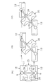
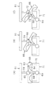
図17は本発明に係る第12実施例の要部を示した縦断面図である。本実施例は前記第11実施例の変形例である。本実施例に係る免震装置90は、中間支持体91を移動可能に貫通支持する支軸として1本からなる長尺の支軸92を使用した点に特徴がある。支軸92の下端部は、下部支持体93に設けた球面自在軸受け等の自在支持部94を介してあらゆる方向に傾斜し得るように回動自在に支持している。また、支軸92の他側は、上部支持体95に設けた自在支持部96を移動可能に貫通して上方に突出した状態にあり、前記自在支持部96おいて回動自在に支持されている。そして、自在支持部96から突出した支軸92の上部は、上部支持体95に形成した開口部97、上部座板98に形成した開口部99及び躯体側2に形成した開口部100を介して上方に延びた状態に設置される。
【0035】
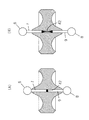
図18は前記第12実施例の要部の挙動を示した動作説明図である。図示のように、本実施例に係る免震装置90の地震時における免震動作に関しては、前記第11実施例と基本的に異なるところはなく、同様の挙動を示す。すなわち、状態(A)に示した躯体側2と地盤側4との間に水平方向のズレがない平常状態において、地震等の外力が作用してその水平方向成分により躯体側2と地盤側4との間に水平方向の相対的な変位が生じると、状態(B)に示したように1本の長尺の支軸92が中間支持体91の支軸嵌合部101に形成した中央孔部102内を相対移動しながら、下部支持体93側に配設した下方の自在支持部94を中心に回動して傾斜する。すなわち、図示のように、支軸92が特定点としての自在支持部94,96を結ぶ軸線上に変位する。この支軸92の傾斜に伴って中間支持体91も傾斜し、その筒状部103の上端部と上部支持体95に形成した上部支持面104との接触部及び筒状部103の下端部と下部支持体93に形成した下部支持面105との接触部が移動して、躯体側2の荷重を支持しながら地盤側4との相対的な変位を吸収することになる。そして、躯体側2と地盤側4との間の相対的な変位が更に大きくなると、状態(C)に示したように、より大きな傾斜状態に移行することになる。また、躯体側2と地盤側4との間の相対的な変位が縮小すれば、逆に辿って傾斜角が縮小する方向に移行することになる。
【0036】
【発明の効果】
本発明によれば、次の効果を得ることができる。
(1)免震装置としての大きさの割に躯体側と地盤側との間の大きな相対的変位に対応することができ、大きな振幅に対する絶縁機能を得ることが可能である。
(2)中間支持体や上部支持体あるいは下部支持体に形成する支持面に関する具体的形状の設定の仕方により、復帰機能の有無や、その復帰特性を調整したり、更にはトリガ機能や動作範囲の規制も可能であり、設定の自由度がきわめて大きい。
(3)支軸として上部支軸と下部支軸の組合せを採用する場合には、それらの先端部間をゴム等の弾性材等からなる伸縮材にて連結し、適度の初期張力を付加してトリガ機能を付加したり、復帰特性や減衰特性を向上することも可能である。
(4)また、上部支軸と下部支軸の先端部間に流体圧ダンパ手段を組込み、その減衰特性を調整することにより、免震装置としてのトリガ機能や減衰機能を付加することも可能である。
(5)また、上部支軸と下部支軸の先端部間をワイヤ等で連結することにより、免震装置としての動作範囲を規制することも可能である。
【図面の簡単な説明】
【図1】 本発明に係る第1実施例の設置状態を示した縦断面図である。
【図2】 同第1実施例の要部の挙動を示した動作説明図である。
【図3】 第2実施例の要部の挙動を示した動作説明図である。
【図4】 第3実施例の要部の挙動を示した動作説明図である。
【図5】 同第3実施例の部分拡大図である。
【図6】 第4実施例の要部の挙動を示した動作説明図である。
【図7】 第5実施例の要部の挙動を示した動作説明図である。
【図8】 第6実施例の要部を示した縦断面図である。
【図9】 第7実施例の要部を示した縦断面図である。
【図10】 第8実施例の要部を示した縦断面図である。
【図11】 第9実施例の要部を示した縦断面図である。
【図12】 第10実施例の要部を示した縦断面図である。
【図13】 同第10実施例の要部の挙動を示した動作説明図である。
【図14】 第11実施例の要部を示した縦断面図である。
【図15】 中間支持体に関する実施例を示した横断面図である。
【図16】 同第11実施例の要部の挙動を示した動作説明図である。
【図17】 第12実施例の要部を示した縦断面図である。
【図18】 第12実施例の要部の挙動を示した動作説明図である。
【符号の説明】
1…免震装置、2…躯体側、3…座板、4…地盤側、5…座板、6…自在支持部、7…上部支軸、8…自在支持部、9…下部支軸、10…中間支持体、11…盤状部、12…上部支持体、13…下部支持体、14…上部支持面、15…下部支持面、16…中央孔部、17,18…筒状部、19…中間支持体、20…盤状部、21…上部支持面、22…下部支持面、23…中間支持体、24…盤状部、25…上部支持面、26…下部支持面、27,28…トリガ当接部、29…中間支持体、30…盤状部、31…上部支持面、32…下部支持面、33,34…係止段部、35…中間支持体、36…盤状部、37…上部支持面、38…下部支持面、39,40…規制用傾斜部、41…ワイヤ、42…伸縮材、43…上部支軸、44…下部支軸、45…軸受部、46…免震装置、47…中間支持体、48…支軸、49…下部支持体、50…自在支持部、51…上部支持体、52…自在支持部、53…開口部、54…上部座板、55,56…開口部、57…免震装置、58…上板、59…支軸体、60…球状部、61…上部支持体、62…嵌合凹部、63…盤状部、64…下部支持面、65…中央孔、66…中間支持体、67…底部、68…下部支軸、69…自在支持部、70…筒状部、71…下部支持体、72…嵌合凹部、73…嵌合凸部、74…免震装置、75…上部支持体、76…上部支持面、77…自在支持部、78…上部支軸、79…下部支持体、80…下部支持面、81…自在支持部、82…下部支軸、83…中間支持体、84…支軸嵌合部、85…筒状部、86…連結板部、87…中央孔部、88…連結片部、89…空間部、90…免震装置、91…中間支持体、92…支軸、93…下部支持体、94…自在支持部、95…上部支持体、96…自在支持部、97…開口部、98…上部座板、99,100…開口部、101…支軸嵌合部、102…中央孔部、103…筒状部、104…上部支持面、105…下部支持面
[0001]
BACKGROUND OF THE INVENTION
The present invention relates to a seismic isolation device that insulates a building side of a building from a ground side such as foundation concrete and protects the building from external forces such as earthquakes.
[0002]
[Prior art]
Various types of building seismic isolation devices have been known. For example, various types are known, such as a type using laminated rubber, a type using rolling bearings, a type using sliding bearings, etc. Seismic isolation / damping structure and equipment ", published by the Invention Association of Japan on July 25, 2000). By the way, there is a range of horizontal displacement that can be handled by the seismic isolation device, that is, an allowable operating range of the seismic isolation device, and it is necessary to increase the scale of the device to increase this operating range. There are problems such as high costs and large installation space. Also in the various types of seismic isolation devices in the prior art, an accurate solution regarding this point has not been obtained.
[0003]
[Problems to be solved by the invention]
The present invention has been developed in view of the state of the prior art as described above, and can have a large operating range for the size of the device, and has an insulation function for a large amplitude, and the insulation function is In addition, a function to return to the original installation state (return function), a function to start operation when the seismic action exceeds a predetermined value (trigger function), or to restrict the operation range, etc. The purpose is to provide a seismic isolation device with a high degree of freedom.
[0004]
[Means for Solving the Problems]
In order to solve the above-mentioned problem, in the invention of claim 1, at least for the housing side or the ground side. So that it can tilt in either direction Freely fit on a pivot that is supported rotatably By Axis connecting a specific point on the frame side and a specific point on the ground side Relative to the pivot shaft An intermediate support having a plate-like portion provided movably, an upper support disposed between the intermediate support and the housing side, and disposed between the intermediate support and the ground side; And a lower support, and at least one of the upper support and the lower support is brought into contact with a support surface formed on the disk-like portion of the intermediate support so as to be relatively movable. The present invention is characterized in that it can cope with a large relative displacement between the frame side and the ground side for the size as a seismic isolation device. That is, it is possible to exert an insulating function against a relative displacement that is large relative to the scale of the device.
[0005]
In invention of Claim 2, at least with respect to the frame side or the ground side So that it can tilt in either direction Freely fit on a pivot that is supported rotatably By Axis connecting a specific point on the frame side and a specific point on the ground side Relative to the pivot shaft An intermediate support having a cylindrical portion provided movably, an upper support disposed between the intermediate support and the housing side, and disposed between the intermediate support and the ground side. The lower support is provided, and a technical means is adopted in which the cylindrical portion of the intermediate support is brought into contact with a support surface formed on at least one of the upper support and the lower support so as to be relatively movable. The present invention is characterized in that the support surface for supporting relative movement is formed on the intermediate support side in the invention of claim 1, whereas it is formed on the upper support or the lower support side. It has basically the same function as that of the first aspect of the invention.
[0006]
According to a third aspect of the present invention, the intermediate support body is arranged along the axis of the upper support shaft that is rotatably supported on the housing side and the lower support shaft that is rotatably supported on the ground side. relative It was designed to fit loosely so that it could move. According to a fourth aspect of the present invention, a support shaft rotatably supported on the ground side is passed through the intermediate support, and the intermediate support is moved along the axis of the support. relative In addition to being loosely fitted so as to be movable, the other side of the support shaft is passed through a free support portion disposed on the housing side so as to be rotatably supported. That is, in the invention of claim 3, the intermediate support is mounted by using the support shafts that are divided vertically between the upper support shaft and the lower support shaft. relative In contrast to the loosely fitted fit, the invention of claim 4 is different in that a single long support shaft is used. It should be noted that the space between the intermediate support and the support shaft is only in the axial direction of the support shaft, for example, by key connection, spline connection, or a support shaft having a rectangular cross section and a loose fitting hole. relative It may be configured so as to be movably loosely fitted and to prevent relative rotational movement (claim 5).
[0007]
The invention according to claim 6 relates to the invention according to claim 1, wherein the upper support is brought into contact with the upper support surface of the disk-shaped portion of the intermediate support so as to be movable relative to the intermediate support, and the lower support is brought into contact with the intermediate support. The technical means of making it contact with the lower support surface of the disk-shaped part of a body so that relative movement was possible was employ | adopted. In the invention according to claim 7, the upper support surface of the disk-shaped portion of the intermediate support and / or the lower support that contacts the upper support so as to be relatively movable contact each other. As the vertical cross-sectional shape of the lower support surface of the disk-shaped part, a concave curved surface was adopted in the radial direction from the center part of the disk-shaped part.
[0008]
In the invention of claim 8, regardless of the horizontal relative movement distance between the specific point on the chassis side and the specific point on the ground side, the contact portion between the upper support and the intermediate support side, and the lower portion The distance in the vertical direction between the support and the contact portion on the intermediate support side was always set to be constant. The present invention relates to a seismic isolation device of a type that does not have a return function suitable when a return means is separately installed. In the invention of claim 9, as the relative movement distance in the horizontal direction between the specific point on the frame side and the specific point on the ground side increases, the contact portion between the upper support and the intermediate support, The vertical distance between the lower support and the contact portion on the intermediate support side was set to be large. According to the present invention, the housing side rises in accordance with the relative movement distance in the horizontal direction, and the position energy increases. Therefore, it is possible to add a return function for returning to a direction with a small relative displacement in which the position energy decreases. It is.
[0009]
According to a tenth aspect of the present invention, the upper support and / or the lower support and the intermediate support are circumferential in a state where there is no horizontal displacement between the specific point on the chassis side and the specific point on the ground side. Configured to contact above. According to the present invention, the upper support and / or the lower support and the intermediate support are arranged on a circumference in a state where there is no horizontal displacement between the specific point on the chassis side and the specific point on the ground side. The trigger function of suppressing the start of the horizontal relative movement between the specific point on the frame side and the specific point on the ground side when the earthquake is larger than a predetermined scale. Addition is possible. That is, here, the stability based on the frictional action due to the line contact on the circumference is utilized, so that the horizontal operation is not started for a small-scale earthquake. The invention of claim 11 employs technical means in which an operation restricting portion for restricting the range of relative movement between the upper support and / or the lower support is provided at the contact portion of the intermediate support. In the invention of claim 12, the upper support shaft and the lower support shaft are provided between the upper support shaft rotatably supported on the housing side and the lower support shaft supported rotatably on the ground side. The technical means of adding a means for suppressing the relative movement between the two is adopted.
[0010]
DETAILED DESCRIPTION OF THE INVENTION
The seismic isolation device according to the present invention can be widely applied as a seismic isolation device for various buildings. Various configurations are possible with respect to the specific configuration of the intermediate support, the upper support or the lower support, and the specific related configuration between them. As a basic form, a form in which a support surface enabling relative movement between the intermediate support and the upper support or the lower support is provided on the intermediate support side as in the invention of claim 1, and claim 2 is provided. As in the present invention, there is a form provided on the upper support or the lower support. In order to obtain the basic function of the present invention, at least one of the upper support and the lower support may be brought into contact with the intermediate support so as to be relatively movable. A configuration in which both the upper support and the lower support are brought into contact with each other so as to be movable relative to the intermediate support, as in the embodiments described later, or the lower support as in the tenth embodiment. It is also possible to adopt a form in which only the body is brought into contact with the intermediate support so as to be relatively movable, or conversely, only the upper support is brought into contact with the intermediate support so as to be relatively movable. Depending on the selection, the specific configuration of the intermediate support, the upper support or the lower support will also change. Incidentally, a form in which a plurality of seismic isolation devices according to the present invention are installed in the vertical direction is also possible.
[0011]
As for the form of forming the support surface on the disk-shaped part of the intermediate support, it is a good example that it is formed in a radially concave curved surface from the center part of the disk-shaped part as illustrated in each example described later. It is not necessarily limited to this. It may be a flat surface or a convex curved surface. Further, it is not necessary that the radial shape of the entire plate-like portion that may come into contact with the upper support or the lower support is formed only by a curved surface, and a linear portion may be mixed in the middle. Regarding the specific shape of the support surface, regardless of whether the support surface is installed on the intermediate support side or on the upper and lower support sides, the contact portion on the upper support side and the contact portion on the lower support side It is also possible to set a configuration that does not have a return function in which the vertical interval between the two sides is always constant, and the interval increases according to the horizontal relative movement distance between the frame side and the ground side. It is also possible to set to a form having a return function. It is also possible to adjust the return characteristics by setting the increase rate of the interval. Furthermore, as in the embodiments described later, it is possible to incorporate a shape suitable for regulation of the trigger function and the operation range. As described above, the features of the present invention also exist in the form where various shapes can be easily set depending on the shape of the support surface formed on the disk-shaped portion of the intermediate support or the upper support or the lower support. To do.
[0012]
The intermediate support has a central hole formed in the center thereof on the housing side. So that it can tilt in either direction On the upper support shaft and the ground side supported rotatably So that it can tilt in either direction By loosely fitting on the lower support shafts supported so as to be rotatable, along the axes of those support shafts relative It can be assembled so as to be movable. In that case, connect the tip of the upper and lower spindles with an elastic material such as rubber, and add a suitable initial tension to add a trigger function or return characteristics. It is also possible to improve the damping characteristics. In addition, it is also possible to utilize the frictional action between both in the loose fitting state of the center hole of the intermediate support and each support shaft for the damping function. In addition, a fluid pressure damper means such as a hydraulic damper or a pneumatic damper is installed between the tip of the upper support shaft and the lower support shaft, and by adjusting its damping characteristics, a trigger function and a damping function as a seismic isolation device can be achieved. It is also possible to add. Furthermore, it is also possible to restrict the operating range as the seismic isolation device by connecting the tip of the upper support shaft and the lower support shaft with a wire or the like. As described above, the features of the present invention also exist where various functions can be added by the connecting means installed between the top ends of the upper support shaft and the lower support shaft. In addition, it cannot be overemphasized that the above-mentioned each form can be selected and comprised according to a case. Incidentally, as in the ninth and twelfth embodiments described later, a single long support shaft is used as a support shaft for penetrating and supporting the intermediate support, and the lower end of the support shaft is While supporting freely through a free support part provided in the lower support body, the other side is movably penetrated through the free support part provided in the upper support body and protrudes upward. A form supported in a freely rotatable manner is also possible.
[0013]
【Example】
FIG. 1 is a longitudinal sectional view showing an installation state of the first embodiment according to the present invention. As shown in the figure, the seismic isolation device 1 according to the present invention is installed between a seat plate 3 installed on the frame side 2 and a seat plate 5 installed on the ground side 4 such as foundation concrete. In this embodiment, the seismic isolation device 1 is on the ground side in the same manner as the upper support shaft 7 supported on the housing side 2 so as to be able to tilt in any direction via a universal support 6 such as a spherical universal bearing. 4 along the axis connecting the lower support shaft 9 rotatably supported by the universal support portion 8. relative An intermediate support 10 provided movably, an upper support 12 disposed between the upper surface of the disk-like part 11 of the intermediate support 10 and the housing side 2, and the disk-like part 11 of the intermediate support 10 The case where it comprised from the lower surface support body 13 arrange | positioned between the lower surface and the ground side 4 was shown. FIG. 1 shows an installation state in a normal state where there is no horizontal displacement between the universal support 6 as a specific point on the frame side 2 and the universal support 8 as a specific point on the ground side 4.
[0014]
In the present embodiment, the upper support surface 14 and the lower support surface 15 formed on the upper and lower surfaces of the plate-like portion 11 of the intermediate support 10 are radially curved from the center of the plate-like portion 11 as shown in the figure. It was formed to become. Further, the free support side of the upper support shaft 7 and the lower support shaft 9 is movably fitted in the central hole portion 16 formed in the center portion of the intermediate support 10. The upper support 12 and the lower support 13 were formed in a cylindrical shape having a low bottom, and the bottoms were fixed to the seat plates 3 and 5 using implantation bolts and nuts, respectively. End portions of the cylindrical portions 17 and 18 of the upper support 12 and the lower support 13 are relatively moved to an upper support surface 14 and a lower support surface 15 formed on the upper and lower surfaces of the plate-like portion 11 of the intermediate support 10. Through the contact, the load on the housing side 2 is sequentially transmitted to the upper support 12, the intermediate support 10, and the lower support 13 and supported by the ground side 4. Note that the end portions of the cylindrical portions 17 and 18 of the upper support 12 and the lower support 13 preferably have an arcuate cross section for smooth movement between the upper support surface 14 and the lower support surface 15. There may be other cross-sectional shapes. Further, sliding members, steel balls or small bearings for improving the smoothness of relative movement may be attached to the ends of the cylindrical portions 17 and 18, and both the support surfaces 14 and 15 are self-lubricated. It may be made of a material or plated. Further, lubricating oil or a rust preventive material may be supplied to those contact portions, or a friction reducing material may be applied, affixed, or impregnated. Furthermore, the periphery of the intermediate support 10 may be blocked from the outside by a dust-proof cover material such as bellows.
[0015]
FIG. 2 is an operation explanatory view showing the behavior of the main part of the first embodiment. The state (A) shows a normal state in which there is no horizontal displacement between the housing side 2 and the ground side 4, and as shown in the figure, the lower end portion of the cylindrical portion 17 of the upper support 12 is Line contact is made on the circumference of the periphery of the upper support surface 14 of the disc-like portion 11 of the intermediate support 10, and the upper end portion of the cylindrical portion 18 of the lower support 13 is the lower support surface 15 of the disc-like portion 11. It is stopped stably in a state of line contact on the circumference of the periphery. In this state, the load on the chassis side is sequentially transmitted to the upper support 12, the intermediate support 10, and the lower support 13 through their circumferential line contacts, and is supported by the ground side.
[0016]
Thus, when an external force such as an earthquake is applied and a horizontal relative component causes a horizontal displacement between the skeleton side 2 and the ground side 4, the upper support shaft as shown in the state (B). 7 and the lower support shaft 9 in the central hole 16 relative While moving, it tilts around the free support parts 6 and 8. That is, as shown in the drawing, the upper support shaft 7 and the lower support shaft 9 are displaced on the axis connecting the free support portions 6 and 8 as specific points. As the upper support shaft 7 and the lower support shaft 9 are inclined, the intermediate support 10 is also inclined, and the end portions of the cylindrical portions 17 and 18 of the upper support 12 and the lower support 13 and the disc shape of the intermediate support 10 are formed. The contact portion of the part 11 with the upper support surface 14 or the lower support surface 15 moves, and the relative displacement with the ground side 4 is absorbed while supporting the load on the housing side 2. Then, when the relative displacement between the housing side 2 and the ground side 4 is further increased, as shown in the state (C), the state is shifted to a larger inclined state. Further, if the relative displacement between the frame side 2 and the ground side 4 is reduced, the inclination angle is traced and the inclination angle is reduced. If the guide support relationship between the upper support shaft 7 and the lower support shaft 9 and the central hole 16 of the intermediate support 10 is set long, theoretically, when the relative displacement further increases from the state (C). Can also respond.
[0017]
In the present embodiment, as shown in the drawing, even when the state (A) is changed to the state (B) and the state (C), the lower end portion and the upper support surface 14 of the cylindrical portion 17 of the upper support 12 are used. The shape of both support surfaces 14 and 15 is set so that the distance Sa between the contact portion between the contact portion and the contact portion between the upper end portion of the cylindrical portion 18 of the lower support 13 and the lower support surface 15 is always constant. Showed the case. Thereby, in this embodiment, the free support portion 6 follows the horizontal track A, and the upper and lower support portions of the upper support 12 are supported regardless of the horizontal relative movement distance between the chassis side 2 and the ground side 4. The vertical interval St between the lower surface of the body 13, that is, the support interval between the chassis side 2 and the ground side 4 is always constant. Incidentally, in the case of the present embodiment, since there is no return function, it is necessary to provide a return means separately. The external energy such as seismic energy is mainly applied to the upper support surface 14 or the lower support formed on the ends of the cylindrical portions 17 and 18 of the upper support 12 and the lower support 13 and the plate-like portion 11 of the intermediate support 10. It is attenuated by friction at the contact portion with the surface 15.
[0018]
FIG. 3 is an operation explanatory view showing the behavior of the main part of the second embodiment according to the present invention. In the following description, the same reference numerals are used for the components common to the first embodiment. This embodiment is characterized in that a return function is added to the first embodiment. Due to the addition of the return function, in this embodiment, the universal support portion 6 gradually moves as shown by the track B as the state (A) is shifted from the normal state (B) to the state (C). Specific shapes of the upper support surface 21 and the lower support surface 22 formed of concave curved surfaces formed on the upper and lower surfaces of the plate-like portion 20 of the intermediate support 19 were set so as to rise. That is, the distance between the contact portion between the lower end portion of the tubular portion 17 of the upper support 12 and the upper support surface 21 and the contact portion between the upper end portion of the tubular portion 18 of the lower support 13 and the lower support surface 22. The specific shapes of the upper support surface 21 and the lower support surface 22 were set so that Sb gradually increased from the state (A) to the state (B) and further to the state (C). Thereby, in the case of a present Example, as it transfers to a state (B) from a state (A) and a state (C) further, the housing side 2 will raise gradually with the upper support body 12, and the energy of a position is stored. It will be. Therefore, a function for returning to the state (A) where the energy of the position is reduced is added. The specific return characteristic can be adjusted through the setting of the rate of change of the interval Sb.
[0019]
FIG. 4 is an operation explanatory view showing the behavior of the main part of the third embodiment according to the present invention. This embodiment is characterized in that a trigger function is added to the first embodiment. As shown in the drawing, in this embodiment, in the normal state shown in the state (A), a concave curved surface formed by the lower end portion of the cylindrical portion 17 of the upper support 12 on the upper surface of the disc-like portion 24 of the intermediate support 23. The upper end of the cylindrical portion 18 of the lower support 13 is in line contact with the peripheral portion of the upper support surface 25 and the peripheral portion of the lower support surface 26 formed of a concave curved surface formed on the lower surface of the disk-shaped portion 24. Stops stably with line contact. As shown in the partially enlarged view of FIG. 5, trigger contact portions 27 and 28 made of small flat surfaces that perform a trigger function are formed around the upper support surface 25 and the lower support surface 26. In addition, as the trigger contact portions 27 and 28, flat surfaces are suitable from the viewpoint of the stability of the contact state and the smoothness of the operation, but other shapes are also possible. By the way, in this embodiment, the housing side 2 is configured to rise via the trigger contact portions 27 and 28 at the start of relative movement between the housing side 2 and the ground side 4. Exemplified the case where the trigger function is exerted by the strong counter force accompanying the rise, but the trigger function is also exhibited by the form not accompanied by the rise of the housing side 2 utilizing the stability based only on the friction caused by the line contact on the circumference. It is possible. Further, between the lower end portion of the support shaft loose fitting portion at the center of the intermediate support 23 and an appropriate portion on the lower support body 13 side and / or the upper end portion of the support shaft loose fit portion at the center of the intermediate support 23 and the upper support. An appropriate elastic means such as a spring is interposed between appropriate parts on the body 12 side, and the trigger function can be adjusted by adjusting the degree of load acting on the trigger contact portions 27 and 28. It is also possible.
[0020]
Therefore, when an external force such as an earthquake is applied in the present embodiment, the lower end portion and the lower portion of the cylindrical portion 17 of the upper support 12 are moved when the state (A) is shifted from the normal state (A) to the state (B). Trigger contact portions 27 and 28 formed on the upper end portion of the cylindrical portion 18 of the support 13 and the upper and lower support surfaces 25 and 26 formed on the upper and lower surfaces of the disk-like portion 24 of the intermediate support 23. From the relationship with the trajectory of the contact portion, the universal support portion 6 follows the track C. Therefore, to move to the state (B), it is necessary to lift the housing side 2 together with the upper support 12. That is, when the movement from the normal state (A) to the state (B) is started, a fairly powerful trigger function that suppresses the movement acts. After reaching the state (B), the process proceeds to the state (C) through the same operation process as in the first embodiment. Although the case where the trigger function is added to the first embodiment has been described above, it goes without saying that the return function and the trigger function can be added by applying to the second embodiment.
[0021]
FIG. 6 is an operation explanatory view showing the behavior of the main part of the fourth embodiment according to the present invention. The present embodiment is characterized in that an operation restricting unit for restricting the operation range as the seismic isolation device is added. As shown in the figure, in this embodiment, the upper support surface 31 formed of concave curved surfaces formed on the upper and lower surfaces of the disk-shaped portion 30 of the intermediate support 29 and the locking step portion 33 formed on the center side of the lower support surface 32. , 34 to restrict the operating range. That is, when an external force such as an earthquake acts and the state (C) is reached from the state (A) through the state (B), the lower end of the cylindrical portion 17 of the upper support 12 and the lower support The upper end portions of the thirteen cylindrical portions 18 are locked to the locking step portions 33 and 34 to restrict the operation range.
[0022]
FIG. 7 is an operation explanatory view showing the behavior of the main part of the fifth embodiment according to the present invention. As in the fourth embodiment, the present embodiment is characterized in that an operation restricting unit that restricts the operation range as the seismic isolation device is added. As shown in the figure, in the present embodiment, the restricting inclined portions 39 and 40 are formed on the center side of the upper support surface 37 and the lower support surface 38 formed of concave curved surfaces formed on the upper and lower surfaces of the plate-like portion 36 of the intermediate support 35. Is provided to regulate the operating range. In the case of the present embodiment, when an external force such as an earthquake acts and the state (C) passes from the state (A) to the state (C), the lower end of the cylindrical portion 17 of the upper support 12 and The upper end portion of the cylindrical portion 18 of the lower support 13 is engaged with the restricting inclined portions 39 and 40, and the relative movement between the upper support 12 and the lower support 13 thereafter increases the housing side 2. Will accompany. Since a larger external force in the horizontal direction is required for the rising of the housing side 2, the relative movement between the upper support 12 and the lower support 13 is suppressed and the operation range is restricted. In this embodiment, since the restricting inclined portions 39 and 40 are employed as the operation range restricting means, the restricting action is gentler than that of the locking step portions 33 and 34.
[0023]
FIG. 8 is a longitudinal sectional view showing an essential part of a sixth embodiment according to the present invention. The present embodiment also has a feature in that an operation restricting unit that restricts the operation range as the seismic isolation device is added. As shown in the figure, in this embodiment, a wire 41 or the like connects the upper support shaft 7 that is rotatably supported on the housing side 2 and the lower support shaft 9 that is rotatably supported on the ground side 4. Thus, a technical means for restricting the relative movement between the upper support shaft 7 and the lower support shaft 9 to a predetermined range was adopted. That is, when the wire 41 is stretched as illustrated, the operation as the seismic isolation device is restricted. It should be noted that a plurality of operation restricting means of the fourth to sixth embodiments described above can be adopted and installed simultaneously.
[0024]
FIG. 9 is a longitudinal sectional view showing an essential part of a seventh embodiment according to the present invention. In this embodiment, the upper support shaft 7 and the lower support shaft 7 are supported between the upper support shaft 7 that is rotatably supported on the frame side 2 and the lower support shaft 9 that is supported to be rotatable on the ground side 4. It is characterized in that means for suppressing relative movement with respect to the shaft 9 is added. As shown in the figure, in this embodiment, as means for suppressing relative movement between the upper support shaft 7 and the lower support shaft 9, an elastic material such as rubber is provided between the upper support shaft 7 and the lower support shaft 9. The technical means of connecting using the elastic material 42 which has the attenuation function which consists of materials etc. was employ | adopted. Thus, when an external force such as an earthquake is applied to shift from the state (A) to the state (B), the expansion / contraction material 42 is stretched. Therefore, an appropriate initial tension is applied to the expansion / contraction material 42 to trigger. It is possible to add a function and improve the return characteristic and the attenuation characteristic.
[0025]
FIG. 10 is a longitudinal sectional view showing an essential part of an eighth embodiment according to the present invention. In the present embodiment, means for suppressing the relative movement between the upper support shaft 43 rotatably supported on the housing side 2 and the lower support shaft 44 rotatably supported on the ground side 4 is provided. It has a feature in the added point. As shown in the figure, in this embodiment, as a means for suppressing relative movement between the upper support shaft 43 and the lower support shaft 44, a hydraulic damper or an empty space is provided between the upper support shaft 43 and the lower support shaft 44. A conventional fluid pressure damper means including a pressure damper is incorporated, and for example, a damper technique is adopted in which a damping function is added by a fluid resistance when flowing through a throttle portion (not shown) installed in the upper support shaft 43. Therefore, when an external force such as an earthquake is applied, the upper support shaft 43 and the lower support shaft 44 are inclined and a relative movement occurs between them. The damping function of the damper means acts. Therefore, by appropriately adjusting the damping characteristic of the fluid pressure damper means, it is possible to add a trigger function or a damping function as a seismic isolation device. Furthermore, the free end side fitting portion of the upper support shaft 43 and the lower support shaft 44 is formed on the tapered outer surface and the inner surface and loosely fitted in a lubricated state, thereby suppressing relative movement therebetween, It is also possible to regulate the movement range. In the figure, reference numeral 45 denotes a bearing portion having a dustproof function.
[0026]
FIG. 11 is a longitudinal sectional view showing an essential part of a ninth embodiment according to the present invention. This embodiment is a modification of the first embodiment. The seismic isolation device 46 according to the present embodiment is characterized in that a single long support shaft 48 is used as a support shaft for penetrating and supporting the intermediate support 47. The lower end portion of the support shaft 48 is rotatably supported so as to be inclined in any direction via a free support portion 50 such as a spherical universal bearing provided on the lower support 49. Further, the other side of the support shaft 48 is in a state of projecting upward through a free support portion 52 provided on the upper support 51, and is rotatably supported by the free support portion 52. Yes. And the upper part of the spindle 48 which protruded from the universal support part 52 is via the opening part 53 formed in the upper support body 51, the opening part 55 formed in the upper seat plate 54, and the opening part 56 formed in the housing side 2. As shown in FIG. It is installed in a state extending upward. Incidentally, regarding the seismic isolation operation during the earthquake of the seismic isolation device 46 according to the present embodiment, there is basically no difference from the first embodiment, and the same behavior is shown.
[0027]
FIG. 12 is a longitudinal sectional view showing the main part of a tenth embodiment according to the present invention, and FIG. 13 is an operation explanatory view showing the behavior of the main part. In the seismic isolation device according to the present embodiment, each of the above-described embodiments is relatively moved to the upper support surface or the lower support surface in which the upper support 12 and the lower support 13 are both formed on the upper and lower surfaces of the plate-like portion of the intermediate support. In contrast to adopting a form that can be contacted, it has a great feature in that it adopts a form in which only the lower support is brought into contact with the lower support surface of the disk-shaped part of the intermediate support so as to be relatively movable Have. As shown in FIG. 12, the seismic isolation device 57 according to this embodiment includes an upper plate 58 fixed to the seat plate 3 installed on the housing side 2, a support shaft 59 fixed to the upper plate 58, and An upper support 61 composed of a spherical portion 60 installed at the tip portion, and a fitting concave portion 62 that fits in a freely rotatable manner so as to be inclined with respect to the spherical portion 60 in all directions, A lower support surface 64 is formed by forming the lower surface of 63 into a curved surface that is concave in the radial direction, and an intermediate support 66 having a central hole 65 formed in the central portion, and a bottomed cylindrical shape. The lower support shaft 68 is fixed to the seat plate 5 installed on the ground side 4 such as foundation concrete and is inserted into the center hole 65 of the intermediate support 66 so as to be relatively movable at the center of the upper surface of the bottom 67. The lower end is in any direction via a universal support 69 such as a spherical universal bearing. A lower support body which is rotatably supported so as to be inclined, and an upper end portion of the cylindrical portion 70 is brought into contact with a lower support surface 64 formed on the lower surface of the disk-shaped portion 63 of the intermediate support body 66 so as to be relatively movable. 71. The support shaft 59 can be formed in a tapered shape or the like having a larger diameter on the upper side. Furthermore, in this embodiment, a conical fitting recess 72 is formed in the lower portion of the spherical portion 60, and a conical fitting protrusion that can be fitted into the fitting recess 72 at the tip of the lower support shaft 68. A trigger function is added by forming the portion 73 and fitting the fitting concave portion 72 and the fitting convex portion 73 in a normal installation state.
[0028]
When an external force such as an earthquake is applied, the relative displacement amount between the upper support 61 and the lower support 71 is changed from the normal installation state shown in the state (A) as shown in FIG. Accordingly, the state (B) and the state (C) are shifted to. In the transition from the state (A) to the state (B), the fitting concave portion 72 formed at the lower portion of the spherical portion 60 and the fitting convex portion 73 formed at the distal end portion of the lower support shaft 68 are fitted. Since this needs to be escaped from, this functions as a trigger means. After that, the upper end portion of the cylindrical portion 70 of the lower support 71 is relatively moved while contacting the lower support surface 64 formed of a concave curved surface formed on the lower surface of the disc-like portion 63 of the intermediate support 66. In the same manner as the first embodiment, an insulating function between the housing side 2 and the ground side 4 is exhibited. Incidentally, in the case of the present embodiment, since the upper support 61 operates integrally with the intermediate support 66, the amount of relative displacement in the horizontal direction that can be absorbed is half that of the previous embodiment. In the embodiment shown in FIG. 13, there is a case where the distance between the upper surface of the upper plate 58 and the lower surface of the bottom portion 67 of the lower support 71 does not have a return function with respect to the relative displacement in the horizontal direction. Although illustrated, as in the case of the above-described embodiment, the relative direction in the horizontal direction depends on how to set the specific shape of the lower support surface 64 formed of a concave curved surface formed on the lower surface of the disk-shaped portion 63 of the intermediate support 66. A return function can be added by setting the distance between the upper surface of the upper plate 58 and the lower surface of the bottom 67 of the lower support 71 in accordance with the displacement. In addition, the technical means described in each of the above-described embodiments can be applied to the present embodiment as necessary.
[0029]
Next, another embodiment will be described with reference to FIGS. FIG. 14 is a longitudinal sectional view showing an essential part of an eleventh embodiment according to the present invention. As shown in the figure, the seismic isolation device 74 according to the present invention is provided between the seat plate 3 installed on the housing side 2 and the seat plate 5 installed on the ground side 4 such as foundation concrete, as in the above-described embodiments. Installed. In the present embodiment, an upper support surface 76 is formed on the lower surface peripheral portion of the upper support 75 fixed to the housing side 2 with the seat plate 3 interposed therebetween, and a free support portion 77 made of a spherical universal bearing or the like is provided at the center of the lower surface. The upper support shaft 78 was rotatably supported via the universal support portion 77 so that the upper support shaft 78 can be inclined in any direction. In addition, a lower support surface 80 is formed around the upper surface of the lower support 79 fixed to the ground side 4 with the seat plate 5 interposed therebetween, and a free support portion 81 made of a spherical universal bearing or the like is disposed at the center of the upper surface. The upper support shaft 82 is rotatably supported through the universal support portion 81 so as to be inclined in any direction. As shown in the figure, an intermediate support 83 is disposed between the upper support 75 and the lower support 79. The intermediate support 83 includes a support shaft fitting portion 84 located at the center, a cylindrical portion 85 located at the peripheral portion, and a connecting plate portion connecting the support shaft fitting portion 84 and the cylindrical portion 85. 86. The upper support shaft 78 and the lower support shaft 82 are loosely fitted into a central hole 87 formed in the support shaft fitting portion 84 from above and below, and the intermediate support 83 is connected along the axis connecting the free support portions 77 and 81. relative Support in a movable manner. In addition, the cylindrical portion 85 of the intermediate support 83 is in contact with the upper support surface 76 formed at the upper periphery of the lower surface of the upper support 75 and the lower end is formed at the upper periphery of the lower support 79. By contacting the lower support surface 80, the load on the housing side 2 acting on the upper support 75 is transmitted to the ground side 4 via the lower support 79. As described above, with respect to the fitting state of the upper support shaft 78 or the lower support shaft 82 and the central hole 87, only the movement in the axial direction is allowed and the relative rotation is prevented. May be.
[0030]
FIG. 15 is a cross-sectional view showing an embodiment relating to an intermediate support. In the figure, the shape shown as Example A shows the AA cross section of the intermediate support 83 used in the eleventh example shown in FIG. As shown in the figure, regarding the cross-sectional shape of the intermediate support, as illustrated in Examples B to E, the support shaft fitting portion 84 and the cylindrical portion 85 are replaced with the connecting plate portion 86. By connecting the connecting pieces 88 with an appropriate number of connecting pieces 88, a space 89 can be formed between the connecting pieces 88 to reduce the material and reduce the weight.
[0031]
FIG. 16 is an operation explanatory view showing the behavior of the main part of the eleventh embodiment. The state (A) shows a normal state in which there is no horizontal displacement between the housing side 2 and the ground side 4. As shown in the figure, the upper end and the lower end of the cylindrical portion 85 of the intermediate support 83 are respectively circumferential with respect to the upper support surface 76 formed on the upper support 75 and the lower support surface 80 formed on the lower support 79. It is in a state of line contact with the top and is stably stopped. In this state, the load on the frame side 2 is sequentially transmitted to the upper support 75, the intermediate support 83, and the lower support 79 via the line contact on the circumference thereof, and is supported by the ground side 4. .
[0032]
Thus, when an external force such as an earthquake is applied and a horizontal relative component causes a horizontal displacement between the skeleton side 2 and the ground side 4, the upper support shaft as shown in the state (B). 78 and the lower support shaft 82 are formed in the center hole 87 formed in the support shaft fitting portion 84 of the intermediate support 83. relative While moving, it tilts around the free support portions 77 and 81. That is, as shown in the drawing, the upper support shaft 78 and the lower support shaft 82 are displaced on the axis connecting the free support portions 77 and 81 as specific points. As the upper support shaft 78 and the lower support shaft 82 are inclined, the intermediate support 83 is also inclined, and the upper and lower support surfaces 76 and 80 of the upper support 75 and the lower support 79 and the cylindrical portion 85 of the intermediate support 83 are vertically moved. The contact portion with the end portion moves, and the relative displacement with the ground side 4 is absorbed while supporting the load on the housing side 2. Then, when the relative displacement between the housing side 2 and the ground side 4 is further increased, as shown in the state (C), the state is shifted to a larger inclined state. Further, if the relative displacement between the frame side 2 and the ground side 4 is reduced, the inclination angle is traced and the inclination angle is reduced.
[0033]
In the present embodiment, as shown in the drawing, even when the state (A) is changed to the state (B) and the state (C), the upper end portion and the upper support 75 of the cylindrical portion 85 of the intermediate support 83 are used. The distance between the contact portion with the upper support surface 76 formed on the lower support surface 80 formed on the lower support 79 and the lower end portion of the cylindrical portion 85 of the intermediate support 83 and the lower support surface 80 is always constant. The case where the shape of both the support surfaces 76 and 80 was set was shown. Thus, in this embodiment, the vertical distance between the upper surface of the upper support 75 and the lower surface of the lower support 79 is independent of the horizontal relative movement distance between the chassis side 2 and the ground side 4. That is, the support interval between the chassis side 2 and the ground side 4 is always kept constant. In the case of the present embodiment, since no return function is provided, it is necessary to provide a return means separately. Incidentally, as in the case of the above-described embodiment, the shape of the support surfaces 76 and 80 formed on the upper support 75 and the lower support 79 is changed, and the horizontal relative displacement between the chassis side 2 and the ground side 4 is changed. Accordingly, if the vertical distance between the upper surface of the upper support 75 and the lower surface of the lower support 79 is set to be increased, it is possible to add a return function.
[0034]
FIG. 17 is a longitudinal sectional view showing an essential part of a twelfth embodiment according to the present invention. This embodiment is a modification of the eleventh embodiment. The seismic isolation device 90 according to the present embodiment is characterized in that a single long support shaft 92 is used as a support shaft that penetrates and supports the intermediate support 91 in a movable manner. The lower end portion of the support shaft 92 is rotatably supported so as to be inclined in any direction via a free support portion 94 such as a spherical universal bearing provided on the lower support 93. In addition, the other side of the support shaft 92 is in a state of projecting upward through a free support portion 96 provided on the upper support body 95, and is rotatably supported by the free support portion 96. Yes. The upper portion of the support shaft 92 protruding from the universal support portion 96 is connected to an opening 97 formed in the upper support 95, an opening 99 formed in the upper seat plate 98, and an opening 100 formed in the housing side 2. It is installed in a state extending upward.
[0035]
FIG. 18 is an operation explanatory view showing the behavior of the main part of the twelfth embodiment. As shown in the drawing, the seismic isolation operation of the seismic isolation device 90 according to the present embodiment is basically not different from the eleventh embodiment and shows the same behavior. That is, in a normal state where there is no horizontal displacement between the skeleton side 2 and the ground side 4 shown in the state (A), an external force such as an earthquake acts and the horizontal component causes the skeleton side 2 and the ground side 4 to act. When a relative displacement in the horizontal direction occurs between the two and the center hole formed in the support shaft fitting portion 101 of the intermediate support 91 by one long support shaft 92 as shown in the state (B). Inside part 102 relative While moving, it tilts around a lower universal support 94 disposed on the lower support 93 side. That is, as shown in the drawing, the support shaft 92 is displaced on the axis connecting the universal support portions 94 and 96 as specific points. As the support shaft 92 is inclined, the intermediate support 91 is also inclined, and a contact portion between the upper end portion of the cylindrical portion 103 and the upper support surface 104 formed on the upper support 95 and a lower end portion of the cylindrical portion 103 The contact portion with the lower support surface 105 formed on the lower support body 93 moves, and the relative displacement with the ground side 4 is absorbed while supporting the load on the housing side 2. Then, when the relative displacement between the housing side 2 and the ground side 4 is further increased, as shown in the state (C), the state is shifted to a larger inclined state. Further, if the relative displacement between the frame side 2 and the ground side 4 is reduced, the inclination angle is traced and the inclination angle is reduced.
[0036]
【The invention's effect】
According to the present invention, the following effects can be obtained.
(1) It is possible to deal with a large relative displacement between the frame side and the ground side for the size as a seismic isolation device, and it is possible to obtain an insulating function against a large amplitude.
(2) The presence / absence of the return function, the return characteristics, and the trigger function and operating range are adjusted according to the specific shape of the support surface formed on the intermediate support, upper support or lower support. Regulation is also possible, and the degree of freedom of setting is extremely large.
(3) When adopting a combination of upper and lower spindles as the spindle, connect their tip parts with an elastic material made of elastic material such as rubber, and apply appropriate initial tension. It is also possible to add a trigger function and improve the return characteristics and attenuation characteristics.
(4) It is also possible to add a trigger function and a damping function as a seismic isolation device by incorporating a fluid pressure damper means between the tip of the upper and lower spindles and adjusting the damping characteristics. is there.
(5) Moreover, it is also possible to restrict | limit the operation | movement range as a seismic isolation apparatus by connecting between the front-end | tip parts of an upper spindle and a lower spindle with a wire.
[Brief description of the drawings]
FIG. 1 is a longitudinal sectional view showing an installation state of a first embodiment according to the present invention.
FIG. 2 is an operation explanatory diagram showing the behavior of the main part of the first embodiment.
FIG. 3 is an operation explanatory diagram showing the behavior of the main part of the second embodiment.
FIG. 4 is an operation explanatory diagram showing the behavior of the main part of the third embodiment.
FIG. 5 is a partially enlarged view of the third embodiment.
FIG. 6 is an operation explanatory diagram showing the behavior of the main part of the fourth embodiment.
FIG. 7 is an operation explanatory diagram showing the behavior of the main part of the fifth embodiment.
FIG. 8 is a longitudinal sectional view showing a main part of a sixth embodiment.
FIG. 9 is a longitudinal sectional view showing a main part of a seventh embodiment.
FIG. 10 is a longitudinal sectional view showing a main part of an eighth embodiment.
FIG. 11 is a longitudinal sectional view showing a main part of a ninth embodiment.
FIG. 12 is a longitudinal sectional view showing a main part of a tenth embodiment.
FIG. 13 is an operation explanatory diagram showing the behavior of the main part of the tenth embodiment.
FIG. 14 is a longitudinal sectional view showing a main part of an eleventh embodiment.
FIG. 15 is a cross-sectional view showing an embodiment relating to an intermediate support.
FIG. 16 is an operation explanatory view showing the behavior of the main part of the eleventh embodiment.
FIG. 17 is a longitudinal sectional view showing a main part of a twelfth embodiment.
FIG. 18 is an operation explanatory diagram showing the behavior of the main part of the twelfth embodiment.
[Explanation of symbols]
DESCRIPTION OF SYMBOLS 1 ... Seismic isolation device, 2 ... Housing side, 3 ... Seat plate, 4 ... Ground side, 5 ... Seat plate, 6 ... Swivel support part, 7 ... Upper support shaft, 8 ... Swivel support part, 9 ... Lower support shaft, DESCRIPTION OF SYMBOLS 10 ... Intermediate support body, 11 ... Disc-shaped part, 12 ... Upper support body, 13 ... Lower support body, 14 ... Upper support surface, 15 ... Lower support surface, 16 ... Central hole part, 17, 18 ... Cylindrical part, DESCRIPTION OF SYMBOLS 19 ... Intermediate support body, 20 ... Disk-shaped part, 21 ... Upper support surface, 22 ... Lower support surface, 23 ... Intermediate support body, 24 ... Disk-shaped part, 25 ... Upper support surface, 26 ... Lower support surface, 27, 28 ... trigger contact part, 29 ... intermediate support, 30 ... disk-like part, 31 ... upper support surface, 32 ... lower support surface, 33 and 34 ... locking step, 35 ... intermediate support, 36 ... disk-like , 37 ... upper support surface, 38 ... lower support surface, 39, 40 ... regulating inclined portion, 41 ... wire, 42 ... elastic material, 43 ... upper support shaft, 44 ... lower support shaft, 4 DESCRIPTION OF SYMBOLS ... Bearing part, 46 ... Seismic isolation device, 47 ... Intermediate support body, 48 ... Support shaft, 49 ... Lower support body, 50 ... Swivel support part, 51 ... Upper support body, 52 ... Swivel support part, 53 ... Opening part, 54 ... upper seat plate, 55, 56 ... opening, 57 ... seismic isolation device, 58 ... upper plate, 59 ... support shaft, 60 ... spherical portion, 61 ... upper support, 62 ... fitting recess, 63 ... board 64: Lower support surface, 65 ... Center hole, 66 ... Intermediate support, 67 ... Bottom, 68 ... Lower support shaft, 69 ... Swivel support, 70 ... Cylindrical part, 71 ... Lower support, 72 ... Fitting concave part, 73 ... fitting convex part, 74 ... seismic isolation device, 75 ... upper support, 76 ... upper support surface, 77 ... free support part, 78 ... upper support shaft, 79 ... lower support, 80 ... lower part Support surface 81: Swivel support portion 82 ... Lower support shaft 83 ... Intermediate support member 84 ... Support shaft fitting portion 85 ... Cylindrical portion 86 ... Connection plate portion 7 ... Central hole part, 88 ... Connection piece part, 89 ... Space part, 90 ... Seismic isolation device, 91 ... Intermediate support body, 92 ... Support shaft, 93 ... Lower support body, 94 ... Swivel support part, 95 ... Upper support Body 96 ... Swivel support part 97 ... Opening part 98 ... Upper seat plate 99, 100 ... Opening part 101 ... Support shaft fitting part 102 ... Central hole part 103 ... Cylindrical part 104 ... Upper support Surface, 105 ... Lower support surface

Claims (12)

少なくとも躯体側又は地盤側に対していずれの方向にも傾斜し得るように回動自在に支持された支軸に遊嵌することにより、躯体側の特定点と地盤側の特定点とを結ぶ軸線上に変位する前記支軸に対して相対移動可能に設けられた盤状部を有する中間支持体と、該中間支持体と躯体側との間に配設された上部支持体と、前記中間支持体と地盤側との間に配設された下部支持体とを備え、それらの上部支持体及び下部支持体の少なくとも一方を前記中間支持体の盤状部に形成した支持面に相対移動可能に接触させたことを特徴とする免震装置。An axis line connecting a specific point on the frame side and a specific point on the ground side by loosely fitting on a support shaft that is supported so as to be able to tilt at least in either direction with respect to the frame side or the ground side. An intermediate support having a disk-like portion provided so as to be relatively movable with respect to the support shaft displaced upward ; an upper support disposed between the intermediate support and the housing; and the intermediate support A lower support disposed between the body and the ground side, and at least one of the upper support and the lower support can be moved relative to a support surface formed on the disk-shaped portion of the intermediate support. Seismic isolation device characterized by contact. 少なくとも躯体側又は地盤側に対していずれの方向にも傾斜し得るように回動自在に支持された支軸に遊嵌することにより、躯体側の特定点と地盤側の特定点とを結ぶ軸線上に変位する前記支軸に対して相対移動可能に設けられた筒状部を有する中間支持体と、該中間支持体と躯体側との間に配設された上部支持体と、前記中間支持体と地盤側との間に配設された下部支持体とを備え、それらの上部支持体及び下部支持体の少なくとも一方に形成した支持面に前記中間支持体の筒状部を相対移動可能に接触させたことを特徴とする免震装置。An axis line connecting a specific point on the frame side and a specific point on the ground side by loosely fitting on a support shaft that is supported so as to be able to tilt at least in either direction with respect to the frame side or the ground side. An intermediate support having a cylindrical portion provided so as to be relatively movable with respect to the support shaft displaced upward ; an upper support disposed between the intermediate support and the housing; and the intermediate support A lower support disposed between the body and the ground side, and the cylindrical portion of the intermediate support can be moved relative to a support surface formed on at least one of the upper support and the lower support. Seismic isolation device characterized by contact. 前記中間支持体は、躯体側に回動自在に支持された上部支軸及び地盤側に回動自在に支持された下部支軸に対して、それらの軸線に沿って相対移動し得るように遊嵌した請求項1又は2に記載の免震装置。The intermediate support is free to move relative to an upper support shaft rotatably supported on the housing side and a lower support shaft supported rotatably on the ground side along the axis. The seismic isolation device according to claim 1 or 2 fitted. 前記中間支持体に地盤側に回動自在に支持された支軸を貫通させ、前記中間支持体を支軸の軸線に沿って相対移動可能に遊嵌するとともに、前記支軸の他側を躯体側に配設した自在支持部を貫通させて回動自在に支持した請求項1又は2に記載の免震装置。A support shaft rotatably supported on the ground side is passed through the intermediate support body, the intermediate support body is loosely fitted so as to be relatively movable along the axis of the support shaft, and the other side of the support shaft is a housing. The seismic isolation device according to claim 1, wherein the seismic isolation device is rotatably supported by penetrating a universal support portion disposed on the side. 前記中間支持体と該中間支持体に対して軸線方向に相対移動可能に遊嵌される支軸との間の相対回転運動を阻止するように構成した請求項3又は4に記載の免震装置。5. The seismic isolation device according to claim 3, configured to prevent relative rotational movement between the intermediate support and a support shaft that is loosely fitted to the intermediate support so as to be relatively movable in an axial direction. . 前記上部支持体を前記中間支持体の盤状部の上部支持面に対して相対移動可能に接触させ、前記下部支持体を前記中間支持体の盤状部の下部支持面に対して相対移動可能に接触させた請求項1に記載の免震装置。  The upper support is brought into contact with the upper support surface of the disk-shaped portion of the intermediate support so as to be movable relative to the upper support, and the lower support is movable relative to the lower support surface of the disk-shaped portion of the intermediate support. The seismic isolation device according to claim 1, which is brought into contact with. 前記上部支持体が相対移動可能に接触する前記中間支持体の盤状部の上部支持面及び/又は前記下部支持体が相対移動可能に接触する前記中間支持体の盤状部の下部支持面を、その盤状部の中央部から放射方向に凹状の曲面とした請求項1に記載の免震装置。  An upper support surface of a plate-like portion of the intermediate support that contacts the upper support so as to be relatively movable and / or a lower support surface of a plate-like portion of the intermediate support that contacts the lower support so as to be relatively movable. The seismic isolation device according to claim 1, wherein a curved surface that is concave in the radial direction from the center of the disk-shaped portion. 前記躯体側の特定点と地盤側の特定点との間の水平方向の相対移動距離に関係なく、前記上部支持体と前記中間支持体側との接触部と、前記下部支持体と前記中間支持体側との接触部との間の上下方向の間隔が常に一定になるように設定した請求項1又は2に記載の免震装置。  Regardless of the horizontal relative movement distance between the specific point on the housing side and the specific point on the ground side, the contact portion between the upper support and the intermediate support, the lower support and the intermediate support The seismic isolation device according to claim 1 or 2, wherein the vertical distance between the contact portion and the contact portion is always set constant. 前記躯体側の特定点と地盤側の特定点との間の水平方向の相対移動距離が大きくなるにつれて、前記上部支持体と前記中間支持体側との接触部と、前記下部支持体と前記中間支持体側との接触部との間の上下方向の間隔が大きくなるように設定した請求項1又は2に記載の免震装置。  As the relative movement distance in the horizontal direction between the specific point on the chassis side and the specific point on the ground side increases, the contact portion between the upper support and the intermediate support, the lower support, and the intermediate support The seismic isolation device according to claim 1 or 2 set so that an up-and-down direction space between a contact part with a body side may become large. 前記躯体側の特定点と地盤側の特定点との間に水平方向のズレのない状態において、前記上部支持体及び/又は下部支持体と前記中間支持体が円周上で接触するように構成した請求項1又は2に記載の免震装置。  The upper support and / or the lower support and the intermediate support are in contact with each other on a circumference in a state where there is no horizontal deviation between the specific point on the chassis side and the specific point on the ground side. The seismic isolation device according to claim 1 or 2. 前記中間支持体の前記上部支持体及び/又は下部支持体との接触部に、それらの間の相対移動の範囲を規制する動作規制部を設けた請求項1又は2に記載の免震装置。  3. The seismic isolation device according to claim 1, wherein an operation restricting portion that restricts a range of relative movement between the intermediate support and the upper support and / or the lower support is provided at a contact portion. 前記躯体側に回動自在に支持された上部支軸と地盤側に回動自在に支持された下部支軸との間に、それらの上部支軸と下部支軸との間の相対移動を抑制する手段を付加した請求項3に記載の免震装置。  Relative movement between the upper support shaft and the lower support shaft is suppressed between the upper support shaft rotatably supported on the housing side and the lower support shaft supported rotatably on the ground side. The seismic isolation device according to claim 3, further comprising means for performing the operation.
JP2002247021A 2002-08-27 2002-08-27 Seismic isolation device Expired - Fee Related JP3961908B2 (en)

Priority Applications (1)

Application Number Priority Date Filing Date Title
JP2002247021A JP3961908B2 (en) 2002-08-27 2002-08-27 Seismic isolation device

Applications Claiming Priority (1)

Application Number Priority Date Filing Date Title
JP2002247021A JP3961908B2 (en) 2002-08-27 2002-08-27 Seismic isolation device

Publications (2)

Publication Number Publication Date
JP2004084313A JP2004084313A (en) 2004-03-18
JP3961908B2 true JP3961908B2 (en) 2007-08-22

Family

ID=32054767

Family Applications (1)

Application Number Title Priority Date Filing Date
JP2002247021A Expired - Fee Related JP3961908B2 (en) 2002-08-27 2002-08-27 Seismic isolation device

Country Status (1)

Country Link
JP (1) JP3961908B2 (en)

Families Citing this family (2)

* Cited by examiner, † Cited by third party
Publication number Priority date Publication date Assignee Title
JP5841043B2 (en) * 2012-11-01 2016-01-06 有限会社藤井住建 Seismic isolation device for wooden construction
CN119467608A (en) * 2024-10-31 2025-02-18 华北水利水电大学 A vibration isolation and reduction device for a flywheel energy storage device

Also Published As

Publication number Publication date
JP2004084313A (en) 2004-03-18

Similar Documents

Publication Publication Date Title
US6324795B1 (en) Seismic isolation system between floor and foundation comprising a ball and socket joint and elastic or elastomeric element
US4644714A (en) Earthquake protective column support
US3771270A (en) Self-centering horizontally translatable support/hold-down apparatus for building structures and the like
JP3361292B2 (en) Sliding support for seismic isolation devices
JP3961908B2 (en) Seismic isolation device
JP2000304089A (en) Building fall prevention device and pull-out prevention device for laminated rubber isolators
US6367207B1 (en) Friction resistance generator
JP2020109246A (en) Bridge aseismatic device
JP5601644B2 (en) Seismic isolation device with damping device and seismic isolation structure with damping device
JPH09158984A (en) Base isolation device
KR101173683B1 (en) Supporting Apparatus for a construction
JP4439694B2 (en) High-damping frame of high-rise building
JP4843881B2 (en) Coupling damping device using rotary inertia force
JP2000266116A (en) Swinging bearing type base isolation device
JP2755868B2 (en) Seismic isolation device
JP4126436B2 (en) Seismic system for structure and seismic coupling device usable in this system
JP4434966B2 (en) Shaft frame connection structure
JP4234036B2 (en) Seismic isolation device
JP4121787B2 (en) Seismic isolation devices and seismic isolation structures
JPH02248551A (en) Device for exempting building from vibration
JP3732744B2 (en) Seismic isolation method and apparatus
AU6532099A (en) Friction resistance generator
JPH11294529A (en) Seismic isolation device
JP7501321B2 (en) Amplification mechanism and method for assembling the same
JP2002213101A (en) Seismic isolation device and seismic isolation building

Legal Events

Date Code Title Description
A621 Written request for application examination

Free format text: JAPANESE INTERMEDIATE CODE: A621

Effective date: 20050601

A977 Report on retrieval

Free format text: JAPANESE INTERMEDIATE CODE: A971007

Effective date: 20061019

A131 Notification of reasons for refusal

Free format text: JAPANESE INTERMEDIATE CODE: A131

Effective date: 20061101

A521 Written amendment

Free format text: JAPANESE INTERMEDIATE CODE: A523

Effective date: 20061227

A02 Decision of refusal

Free format text: JAPANESE INTERMEDIATE CODE: A02

Effective date: 20070214

A521 Written amendment

Free format text: JAPANESE INTERMEDIATE CODE: A523

Effective date: 20070315

A521 Written amendment

Free format text: JAPANESE INTERMEDIATE CODE: A523

Effective date: 20070413

A911 Transfer of reconsideration by examiner before appeal (zenchi)

Free format text: JAPANESE INTERMEDIATE CODE: A911

Effective date: 20070420

TRDD Decision of grant or rejection written
A01 Written decision to grant a patent or to grant a registration (utility model)

Free format text: JAPANESE INTERMEDIATE CODE: A01

Effective date: 20070515

A61 First payment of annual fees (during grant procedure)

Free format text: JAPANESE INTERMEDIATE CODE: A61

Effective date: 20070517

R150 Certificate of patent or registration of utility model

Free format text: JAPANESE INTERMEDIATE CODE: R150

FPAY Renewal fee payment (event date is renewal date of database)

Free format text: PAYMENT UNTIL: 20110525

Year of fee payment: 4

FPAY Renewal fee payment (event date is renewal date of database)

Free format text: PAYMENT UNTIL: 20130525

Year of fee payment: 6

FPAY Renewal fee payment (event date is renewal date of database)

Free format text: PAYMENT UNTIL: 20140525

Year of fee payment: 7

LAPS Cancellation because of no payment of annual fees