JP3961755B2 - Grip-type switch device - Google Patents
Grip-type switch device Download PDFInfo
- Publication number
- JP3961755B2 JP3961755B2 JP2000281946A JP2000281946A JP3961755B2 JP 3961755 B2 JP3961755 B2 JP 3961755B2 JP 2000281946 A JP2000281946 A JP 2000281946A JP 2000281946 A JP2000281946 A JP 2000281946A JP 3961755 B2 JP3961755 B2 JP 3961755B2
- Authority
- JP
- Japan
- Prior art keywords
- switch
- push button
- case
- state
- cable
- Prior art date
- Legal status (The legal status is an assumption and is not a legal conclusion. Google has not performed a legal analysis and makes no representation as to the accuracy of the status listed.)
- Expired - Fee Related
Links
Images


Classifications
-
- H—ELECTRICITY
- H01—ELECTRIC ELEMENTS
- H01H—ELECTRIC SWITCHES; RELAYS; SELECTORS; EMERGENCY PROTECTIVE DEVICES
- H01H9/00—Details of switching devices, not covered by groups H01H1/00 - H01H7/00
- H01H9/02—Bases, casings, or covers
- H01H9/0214—Hand-held casings
-
- H—ELECTRICITY
- H01—ELECTRIC ELEMENTS
- H01H—ELECTRIC SWITCHES; RELAYS; SELECTORS; EMERGENCY PROTECTIVE DEVICES
- H01H3/00—Mechanisms for operating contacts
- H01H3/02—Operating parts, i.e. for operating driving mechanism by a mechanical force external to the switch
- H01H3/022—Emergency operating parts, e.g. for stop-switch in dangerous conditions
-
- H—ELECTRICITY
- H01—ELECTRIC ELEMENTS
- H01H—ELECTRIC SWITCHES; RELAYS; SELECTORS; EMERGENCY PROTECTIVE DEVICES
- H01H9/00—Details of switching devices, not covered by groups H01H1/00 - H01H7/00
- H01H9/02—Bases, casings, or covers
- H01H9/0214—Hand-held casings
- H01H9/0228—Line cord switches
-
- H—ELECTRICITY
- H01—ELECTRIC ELEMENTS
- H01H—ELECTRIC SWITCHES; RELAYS; SELECTORS; EMERGENCY PROTECTIVE DEVICES
- H01H1/00—Contacts
- H01H1/58—Electric connections to or between contacts; Terminals
-
- H—ELECTRICITY
- H01—ELECTRIC ELEMENTS
- H01H—ELECTRIC SWITCHES; RELAYS; SELECTORS; EMERGENCY PROTECTIVE DEVICES
- H01H2300/00—Orthogonal indexing scheme relating to electric switches, relays, selectors or emergency protective devices covered by H01H
- H01H2300/024—Avoid unwanted operation
-
- H—ELECTRICITY
- H01—ELECTRIC ELEMENTS
- H01H—ELECTRIC SWITCHES; RELAYS; SELECTORS; EMERGENCY PROTECTIVE DEVICES
- H01H2300/00—Orthogonal indexing scheme relating to electric switches, relays, selectors or emergency protective devices covered by H01H
- H01H2300/026—Application dead man switch: power must be interrupted on release of operating member
-
- H—ELECTRICITY
- H01—ELECTRIC ELEMENTS
- H01H—ELECTRIC SWITCHES; RELAYS; SELECTORS; EMERGENCY PROTECTIVE DEVICES
- H01H2300/00—Orthogonal indexing scheme relating to electric switches, relays, selectors or emergency protective devices covered by H01H
- H01H2300/028—Application dead man switch, i.e. power being interrupted by panic reaction of operator, e.g. further pressing down push button
-
- H—ELECTRICITY
- H01—ELECTRIC ELEMENTS
- H01H—ELECTRIC SWITCHES; RELAYS; SELECTORS; EMERGENCY PROTECTIVE DEVICES
- H01H27/00—Switches operated by a removable member, e.g. key, plug or plate; Switches operated by setting members according to a single predetermined combination out of several possible settings
- H01H27/002—Switches operated by a removable member, e.g. key, plug or plate; Switches operated by setting members according to a single predetermined combination out of several possible settings wherein one single insertion movement of a key comprises an unlocking stroke and a switch actuating stroke, e.g. security switch for safety guards
-
- H—ELECTRICITY
- H01—ELECTRIC ELEMENTS
- H01H—ELECTRIC SWITCHES; RELAYS; SELECTORS; EMERGENCY PROTECTIVE DEVICES
- H01H9/00—Details of switching devices, not covered by groups H01H1/00 - H01H7/00
- H01H9/08—Arrangements to facilitate replacement of a switch, e.g. cartridge housing
Description
【0001】
【発明の属する技術分野】
この発明は、片手で把持可能な形状を有するスイッチケースに、押し込み量に応じてOFF,ONに切り換わる押しボタンスイッチが設けられたグリップ式スイッチ装置、及びこのグリップ式スイッチ装置を用いた産業機械用制御装置に関する。
【0002】
【従来の技術】
工場などにおいてロボット等の産業機械が設置される産業機械用制御装置201では、図17に示すように、産業機械(ここでは、産業用ロボット)203の周囲の危険ゾーンを、開閉自在の出入口205を有する安全柵207(仕切手段)などで取り囲むことにより、作業者が産業機械203に巻き込まれるといったトラブルを未然に防止している。そして、産業機械203を通常運転する場合には、安全柵207の外面に取り付けられた操作盤209により、安全柵207の外側から機械203の操作を行っている。
【0003】
また、安全性の観点から、この操作盤209および安全柵207内外の複数箇所には、非常停止スイッチ211が取り付けられている。そして、産業機械203が危険な状態に陥った場合には、安全柵207の内外において、この非常停止スイッチ211を適宜操作することで、制御装置201の主回路への電源を遮断して制御装置201全体を緊急停止させることができる。
【0004】
さらに、安全柵207の出入口205には、安全性の観点から、出入口205の扉213が完全に閉まっていないときには、産業機械203の駆動を停止する安全スイッチ215が設けられている。
【0005】
この安全スイッチ215は、例えば図18に示すように、安全柵207内に設置された産業機械203に電気的に接続されるもので、接点を内蔵したスイッチ本体217と、スイッチ本体217への抜き差しによりスイッチ本体217内の接点を開閉するアクチュエータ219とにより構成される。スイッチ本体217は安全柵207の出入口205周縁の壁面に固着され、またアクチュエータ219は扉213に固着される。そのアクチュエータ219の位置はスイッチ本体217の挿入孔221に対向する位置で、扉213を閉鎖した状態のときにスイッチ本体217の操作部223内に進入する。
【0006】
そして、アクチュエータ219の進入により、スイッチ本体217のスイッチ部225に内蔵される接点が閉状態に切り換わり、安全柵207内の産業機械203への電源が供給されて産業機械203が駆動可能な状態となる。一方、扉213の開放によりアクチュエータ219が操作部223から抜け出たときにはスイッチ部225の接点が開状態に切り換わり、産業機械203への電源が遮断されて機械203が手動操作以外では駆動されないようになる。こうすることで、扉213が開放されている場合には産業機械203が駆動しないため、安全柵207内で作業を行う作業者が、産業機械203に巻き込まれるといったトラブルの発生を防止することができる。
【0007】
ところで、作業者が安全柵207の中に入って産業機械203の手動操作を行ったり、メンテナンス作業を行う場合には、産業機械203との接触による作業中の事故を未然に回避するため、いわゆるイネーブルスイッチ(デッドマンスイッチ)と呼ばれる押しボタンスイッチを備えた教示ペンダント227が用いられる。
【0008】
この教示ペンダント227は、図19に示すように、操作盤209にケーブル229を介して接続することにより、産業機械203にプログラムを教示したり、あるいは産業機械203を作動させたりすることのできる携帯用ユニットであり、主面側に配置された入力用キーボード231と、一側面に配置された押ボタンスイッチ(イネーブルスイッチ)233とを有しており、この押ボタンスイッチ233は、押し込み量に応じて第1のOFF,ON,第2のOFFの各状態に順次切り換わるよう構成されている。なお、押しボタンスイッチ233は教示ペンダント227の裏面側に配置される場合もある。
【0009】
この教示ペンダント227は、押しボタンスイッチ233の押ボタン235が押し込まれていない第1のOFF状態にある場合は、キーボード231を操作してもキー入力がされないようになっている。一方、教示ペンダント227の操作者が産業機械203にプログラムを教示する場合には、押ボタン235を押し込んで押ボタンスイッチ233をON状態に保持したまま、キーボード231からキー入力を行う。このとき、操作者が手動操作される産業機械203の可動部との接触の危険を感じたとき、操作者が押ボタン235から指を離すと、押しボタンスイッチ233は初期状態である第1のOFF状態に戻り、産業機械203が停止する。
【0010】
また、操作者が身の危険を感じたときにパニックに陥って押ボタン235をさらに押し込んでしまった場合には、押しボタンスイッチ233がON状態から第2のOFF状態に移行して産業機械203が停止する。
【0011】
このように、この教示ペンダント227では、押しボタンスイッチ233がON状態のときにのみ、教示ペンダント227のキーボード231からのキー入力が可能であり、また押ボタン235の押込み量に応じて、押しボタンスイッチ233を3つのポジション(第1のOFF状態、ON状態、第2のOFF状態)に設定することができるため、手動操作時の操作者の意図を明確にでき、操作者の安全を確保することができる。
【0012】
ところで、上記のように産業機械203を手動操作する場合において、教示ペンダント227を操作する主たる操作者を補助するため、この操作者以外に複数の補助作業者が安全柵207内に入ることがある。このとき、これらの補助作業者が安全柵207内に入る際には、安全性の観点から、上記した押しボタンスイッチ233と同様の3ポジション式の押しボタンスイッチが設けられたグリップ式スイッチ装置を携帯し、補助作業者がグリップ式スイッチ装置を第2のOFF状態にすることでも、産業機械203を停止させることができるようになっている。
【0013】
このようなグリップ式スイッチ装置の具体例として、例えば図20に示すものがある。同図に示すように、このグリップ式スイッチ装置239は、片手で把持可能なスイッチケース241と、当該スイッチケース241を把持した手で押し込み操作可能な押しボタンスイッチ243とを備え、スイッチケース241内の接点に半田付けにより接続され、かつスイッチケース241と一体化されたケーブル245により、上記した操作盤209と電気的に接続されている。
【0014】
そして、安全柵207内に入る作業者は、片手でグリップ式スイッチ装置239を把持しながら、もう片方の手で作業を行う。ここで、産業機械203にプログラムの教示を行う場合には、教示ペンダント227の押しボタンスイッチ233のみならず、すべてのグリップ式スイッチ装置239の押しボタンスイッチ243をON状態にしなければ、産業機械203にプログラムの教示が行えないようにし、こうすることで作業のいっそうの安全化を図っている。
【0015】
また、他の具体例としては、上記したグリップ式スイッチ装置と基本的な構成や機能がほぼ同一で、防水コネクタによりスイッチケース内の接点とケーブルとが接離自在に接続されたものがある。
【0016】
【発明が解決しようとする課題】
ところで、このようなグリップ式スイッチ装置239は、ケーブル245によって操作盤209と接続されているため、安全柵207内ではケーブル245を引き回しながらの作業が多い。そのため、ケーブル245が床面と擦れて破損したり、ケーブル245のスイッチケース241との接続部分が頻繁に捻られることによって破損することがある。
【0017】
しかしながら、図20に示す具体例の装置構成の場合、スイッチケース241とケーブル245とが一体化されているため、ケーブル245のみが破損した場合であっても、ケーブル245のみを交換することができず、ケーブル交換のためにグリップ式スイッチ装置239全体を交換する必要があり、メンテナンスコストが非常に高くなるという問題があった。
【0018】
一方、他の具体例の場合には、上記したようにケーブルとスイッチケース内の接点とが防水コネクタを介して接続されているため、ケーブルが破損した場合には、ケーブルのみの交換は可能であるが、このとき防水コネクタも一緒に交換しなければならず、防水コネクタ自体が非常に高価であることから、やはりメンテナンスコストが高くなるという問題があった。
【0019】
また、作業者が安全柵207内で作業を行う場合には、出入口205の扉213の開放により、安全スイッチ215の接点が開状態となって産業機械203への電源が遮断されるが、安全柵207内での作業中に誤って扉213が閉鎖されることも考えられ、このような場合には、安全スイッチ215においてアクチュエータ219がスイッチ本体217に進入し、産業機械203への電源供給が誤って再開されてしまうおそれがあった。
【0020】
本発明は、上記課題に鑑みてなされたものであり、ケーブルが破損した場合に、低コストで、しかも簡単にケーブルのみを交換可能なグリップ式スイッチ装置を提供することを目的とする。
【0021】
また、安全柵等の仕切手段の出入口が誤って閉鎖された場合であっても、産業機械への電源を遮断状態に保持することができるようにすることも、本発明のもうひとつの目的である。
【0022】
【課題を解決するための手段】
上記した課題を解決するため、本発明にかかるグリップ式スイッチ装置は、片手で把持可能な形状を有するスイッチケースに、押し込み量に応じてOFF,ONに切り換わる押しボタンスイッチが設けられたグリップ式スイッチ装置において、前記スイッチケース内に収容され、前記スイッチケース内に導入されたケーブルの端部と前記押しボタンスイッチの接点とを着脱自在に電気的に接続する接続手段を備え、前記接続手段が、前記スイッチケース内に収容された基部と、前記基部に形成され前記押しボタンスイッチの接点に電気的に接続された複数の一方側導電接続部とを備えた端子台からなり、前記ケーブルの複数の芯線の各先端に取り付けられた他方側導電接続部が、前記各一方側導電接続部のうち対応するものにそれぞれ接離自在に嵌合されて電気的に接続されることを特徴としている。
【0023】
このような構成によると、スイッチケース内に収容された接続手段により、ケーブルが押しボタンスイッチに着脱自在に電気的に接続されているため、例えばケーブルが破損した場合に、ケーブルのみをグリップ式スイッチ装置から取り外して交換することができる。従って、従来のように、ケーブルが破損した場合にグリップ式スイッチ装置全体の交換をする必要がなく、また防水コネクタのような高価なコネクタを設ける必要がないため、ケーブル交換時におけるメンテナンスコストの低減を図ることができる。また、接続手段をなす端子台において、押しボタンスイッチと電気的に接続される端子台の一方側導電接続部と、ケーブルの芯線の先端に取り付けられた他方側導電接続部とが接離自在に嵌合する構成であるため、ケーブルの芯線を端子台から取り外すことでケーブルの交換を行うことができ、しかも安価な端子台により押しボタンスイッチとケーブルとを接続できることから、構成が簡単となり、グリップ式スイッチ装置のメンテナンスコストを低減することが可能になる。
【0028】
また、本発明にかかるグリップ式スイッチ装置は、前記押しボタンスイッチが、その押し込み量の増加に伴い、第1のOFF状態,ON状態,第2のOFF状態に順次に切り換わり、前記押しボタンスイッチが前記第1のOFF状態のときに開または閉状態になり、前記第2のOFF状態のときに閉または開状態となる補助接点を、前記スイッチケース内に設けたことを特徴としている。
【0029】
このような構成によれば、グリップ式スイッチ装置の押しボタンスイッチが、押し込み量の増加に伴って第1のOFF状態、ON状態及び第2のOFF状態に順次に切り換わるため、押しボタンスイッチのON状態から押し込みを解除することにより、押しボタンスイッチを第1のOFF状態にするか、または押しボタンスイッチをON状態からさらに押し込むことにより、押しボタンスイッチを第2のOFF状態にすることができるため、操作者の安全を確保することができる。
【0030】
さらに、第1のOFF状態と第2のOFF状態とで開閉状態の異なる補助接点がスイッチケース内に設けられているため、この補助接点の開閉状態をモニタすることにより、押しボタンスイッチの第1のOFF状態と第2のOFF状態とを識別することができる。
【0031】
また、本発明にかかるグリップ式スイッチ装置は、片手で把持可能な形状を有するスイッチケースに、押し込み量に応じてOFF,ONに切り換わる押しボタンスイッチが設けられたグリップ式スイッチ装置において、前記スイッチケース内に収容され、前記スイッチケース内に導入されたケーブルの端部と前記押しボタンスイッチの接点とを着脱自在に電気的に接続する接続手段を備え、外部装置の非常停止操作用の非常停止スイッチが、前記スイッチケースに設けられていることを特徴としている。
【0032】
このような構成によれば、スイッチケースに非常停止スイッチが設けられているため、例えば、操作者が危険な状態に陥った場合に、外部装置を直接操作することなく、グリップ式スイッチ装置を操作することで、外部装置を非常停止させることができる。従って、非常時における対応を迅速に行うことができ、作業の安全性を向上することができる。
【0033】
また、本発明にかかるグリップ式スイッチ装置は、前記スイッチケースに、外部装置に設けられた安全スイッチに挿脱自在に挿入されるアクチュエータが配設され、前記外部装置が、前記アクチュエータの前記安全スイッチへの挿入時に、前記外部装置側の操作盤による操作が可能なモードに切り換わり、前記アクチュエータの前記安全スイッチからの抜き取り時に、前記外部装置側の操作盤による操作が不可能なモードに切り換わることを特徴としている。
【0034】
このような構成によれば、グリップ式スイッチ装置に設けられたアクチュエータを安全スイッチから抜き取ることにより外部装置側の操作が不可能なモードに切り換わるため、例えばグリップ式スイッチ装置を操作して機械に教示作業を行っている場合に、外部装置側からの機械の操作を不可能にすることができる。従って、教示作業中に誤って外部から機械が操作されるのを防止することができ、作業の安全性を向上することができる。
【0035】
また、本発明にかかるグリップ式スイッチ装置は、前記アクチュエータが、前記スイッチケースに出没自在に設けられていることを特徴としている。
【0036】
このような構成によれば、例えば安全スイッチからアクチュエータを抜き出して機械への教示作業を行う場合、アクチュエータをスイッチケース内に収納することができるため、グリップ式スイッチ装置を携帯して作業する際に、スイッチケースから突出するアクチュエータをスイッチケース内に没入させておけば、アクチュエータが、例えば外部の機械等に接触するのを防止することができる。
【0037】
また、本発明にかかるグリップ式スイッチ装置は、片手で把持可能な形状を有するスイッチケースに、押し込み量に応じてOFF,ONに切り換わる押しボタンスイッチが設けられたグリップ式スイッチ装置において、前記スイッチケース内に収容され、前記スイッチケース内に導入されたケーブルの端部と前記押しボタンスイッチの接点とを着脱自在に電気的に接続する接続手段を備え、前記押しボタンスイッチの押ボタンを一部包被するガード部材が、前記スイッチケースに着脱自在に取り付けられていることを特徴としている。
【0038】
このような構成によれば、ガード部材により押ボタンの一部を包被することで、例えば粘着テープ等を巻き付けることにより押しボタンスイッチをON状態に保持しようとしても、ガード部材により押ボタンの粘着テープによる押圧を阻止できるため、粘着テープの巻き付けにより手で握り込まなくても押しボタンスイッチをON状態に保持するという誤った使用を未然に防止することができる。
【0039】
また、本発明にかかるグリップ式スイッチ装置は、前記押しボタンスイッチのON,OFFの状態を表示する表示手段が、前記スイッチケースに設けられていることを特徴としている。
【0040】
このような構成によれば、押しボタンスイッチのON,OFFの状態を表示する表示手段が設けられているため、グリップ式スイッチ装置の操作者が、押しボタンスイッチの状態を容易に視認することができる。
【0041】
また、本発明にかかるグリップ式スイッチ装置は、他の装置の駆動スイッチが、前記スイッチケースに設けられていることを特徴としている。
【0042】
このような構成によれば、他の装置の駆動スイッチがスイッチケースに設けられているため、グリップ式スイッチ装置の駆動スイッチを操作することで他の装置を操作することもできる。従って、グリップ式スイッチ装置を他の装置の操作手段としても使用することができ、作業の効率化を図ることができる。
【0043】
また、本発明にかかるグリップ式スイッチ装置は、前記スイッチケース内への前記ケーブルの導入部分に防水手段が設けられていることを特徴としている。
【0044】
このような構成によれば、防水手段がスイッチケースのケーブル導入部分に設けられているため、浸水によるグリップ式スイッチ装置の故障を未然に防止することができ、防水対策の必要な環境下であってもグリップ式スイッチ装置を安心して使用することができる。
【0045】
また、本発明にかかるグリップ式スイッチ装置は、前記押しボタンスイッチの押しボタンが、前記スイッチケースの周面に突出して配設され、前記スイッチケースの前記押ボタンの両側に、前記押ボタンよりも突出した突起部が形成されていることを特徴としている。
【0046】
このような構成によれば、押ボタンの両端に、当該押ボタンよりも突出した突起部が形成されているため、押ボタンを両側の突起部によりガードすることができ、例えばグリップ式スイッチ装置を平坦な面上に載置したときに、勝手に押しボタンスイッチが押し込まれてONすることを防止できる。
【0047】
また、本発明にかかるグリップ式スイッチ装置は、前記接続手段が、前記スイッチケース内に収容された基部と、前記基部に形成され前記押しボタンスイッチの接点に電気的に接続された複数の一方側導電接続部とを備えた端子台からなり、
前記ケーブルの複数の芯線の各先端に取り付けられた他方側導電接続部が、前記各一方側導電接続部のうち対応するものにそれぞれ接離自在に嵌合されて電気的に接続されることを特徴としている。
【0048】
このような構成によれば、接続手段をなす端子台において、押しボタンスイッチと電気的に接続される端子台の一方側導電接続部と、ケーブルの芯線の先端に取り付けられた他方側導電接続部とが接離自在に嵌合する構成であるため、ケーブルの芯線を端子台から取り外すことでケーブルの交換を行うことができ、しかも安価な端子台により押しボタンスイッチとケーブルとを接続できることから、構成が簡単となり、グリップ式スイッチ装置のメンテナンスコストを低減することが可能になる。また、スイッチケースに非常停止スイッチを設けたため、外部装置を直接操作することなく、グリップ式スイッチ装置を操作することで、外部装置を非常停止させることができ、非常時における対応を迅速に行うことが可能になる。また、ガード部材により押ボタンの一部を包被することで、例えば粘着テープ等を巻き付けることにより押しボタンスイッチをON状態に保持しようとしても、ガード部材により押ボタンの粘着テープによる押圧を阻止できるため、粘着テープの巻き付けにより手で握り込まなくても押しボタンスイッチをON状態に保持するという誤った使用を未然に防止することが可能になる。
【0049】
【発明の実施の形態】
(第1実施形態)
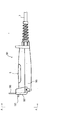
この発明を、産業ロボットなどの産業機械用制御装置に用いられるグリップ式スイッチ装置に適用した場合における第1実施形態について、図1ないし図7を参照して説明する。ただし、図1及び図2は斜視図及び切断側面図、図3はグリップ式スイッチ装置を把持した状態を示す図、図4はスイッチケース内に配設された端子台の斜視図、図5ないし図7はスイッチケース内に配設される押ボタンスイッチの異なる状態における断面図である。
【0050】
本実施形態において、グリップ式スイッチ装置を用いた産業機械用制御装置201の基本的な構成は、図17ないし図19に示すものとほぼ同じであるため、以下では重複した説明を省略し、これらの図も参照して説明することとする。
【0051】
図1及び図2に示すように、本実施形態にかかるグリップ式スイッチ装置1は、片手により把持可能なスイッチケース3と、スイッチケース3に配設される押しボタンスイッチ5と、スイッチケース3にその一端部6が着脱自在に取り付けられるとともに他端部が操作盤209(図17参照)に接続された複数の芯線から成る多芯ケーブル7と、スイッチケース3内に配設され押しボタンスイッチ5の接点とケーブル7とを電気的に接続する接続手段としての端子台9とから構成されている。
【0052】
スイッチケース3は、図1及び図2に示すように、蓋部材11とケース本体13からなり、蓋部材11がケース本体13に着脱自在に装着されている。
【0053】
ケース本体13の一端部にはケーブル7の一端部6が挿入される導入孔15が形成されている。この導入孔15には、円筒状の防水パッキン17が配設されており、この防水パッキン17によりケーブル7の一端部6とケース本体13との隙間が閉塞されて浸水が阻止されている。また、ケーブル7の一端部6の外側には、ゴム等の可撓性部材からなる保護部材19が螺旋状に巻回されており、この保護部材19により、グリップ式スイッチ装置1の操作時にケーブル7の一端部6に外力が直接作用することを防止し、ケーブル7が屈曲したり、大きく捻れたりすることを防止している。
【0054】
さらに、ケース本体13内に挿入されたケーブル7の一端部6は、その被覆が剥離されて複数の芯線21が露出され、これら各芯線21の先端部23の被覆がさらに剥離されて各芯線21内部の導線が露出され、露出された導線部分が端子台9に着脱自在に接続される。ここで、芯線21の先端部23の露出された導線部分が本発明の他方側導電接続部を構成している。
【0055】
また、スイッチケース3には、押しボタンスイッチ5の押ボタン25を一部包被する例えば硬質樹脂からなるガード部材27が着脱自在に取り付けられ、ガード部材27の一端部29がケース本体13の下部にネジ31により取り付けられている。そして、グリップ式スイッチ装置1を操作する作業者が右手でスイッチケース3を把持する場合には、図3(a)に示すように、ガード部材27をスイッチケース3に取り付け、左手でスイッチケース3を把持する場合には、同図(b)に示すように、ガード部材27をスイッチケース3に対して同図(a)と反対向きに取り付けることができる。
【0056】
このように、ガード部材27を取り付けることにより、例えば粘着テープ等を巻き付けることにより押しボタンスイッチ5をON状態に保持しようとしても、ガード部材27により押ボタン25の粘着テープによる押圧を阻止できるため、粘着テープの巻き付けにより手で握り込まなくても押しボタンスイッチ5をON状態に保持するという誤った使用を未然に防止している。
【0057】
ところで、蓋部材11には、その中央部に押ボタン25の挿通用長孔33が形成されており、押しボタンスイッチ5の押ボタン25がスイッチケース3の内側からこの長孔33を介して外方に突出されている。また、蓋部材11の長手方向の両端部には、押ボタン25よりも突出した突起部35a,35bが形成されている。このように突起部35a,35bを形成して押ボタン25の両端側をガードすることで、例えばグリップ式スイッチ装置1を平坦な面上に載置したときに、勝手に押しボタンスイッチ5が押し込まれてONすることを防止している。
【0058】
また、蓋部材11の他端部側端面、つまり一方の突起部35aの端面には、押しボタンスイッチ5のON,OFF状態を異なる発色(例えば、赤色及び緑色)で示す表示手段としての2つのLED37a,37bが配設されており、押しボタンスイッチ5がOFF状態のときには一方の例えばLED37aが点灯し、ON状態のときには他方のLED37bが点灯する。
【0059】
さらに、端子台9は、図2及び図4に示すように、後述する押しボタンスイッチ5の接点を成す端子片71,81と導線39を介して接続される基板41と、この基板41上に設けられ上段部45と下段部47とからなる断面L字形の基部43と、基部43に形成された複数の挿入孔49a,49b内に配設された円筒状の一方側導電接続部51a,51bとにより構成されている。
【0060】
そして、各挿入孔49a,49b内の一方側導電接続部51a,51bには、ケーブル7の各芯線21の導線部分が挿入されると共に、上段部45及び下段部47の上面から各挿入孔49a,49bに向けてネジ53a,53bが螺合され、このネジ53a,53bを締め付けることにより、各芯線21の先端部23の導線部分が一方側導電接続部51a,51bに押圧される。尚、各一方側導電接続部51a,51bは基板41と電気的に接続されており、これにより押しボタンスイッチ5のON、OFF信号が一方側導電接続部51a,51bを介してケーブル7の各芯線21に伝送される。
【0061】
押しボタンスイッチ5は、押ボタン5の押し込み量に応じて第1のOFF状態、ON状態及び第2のOFF状態に順次に切り換わる3ポジション式スイッチであり、例えば図5に示すように、平面視矩形状のスイッチ筐体55と、このスイッチ筐体55に押し込み可能に支持された押ボタン25と、押しボタンスイッチ5のON、OFF状態を切り換える2個のc接点59及び補助接点としての常閉接点61と、押ボタン25の押し込みに連動して各c接点59を開閉させる2つのスイッチング機構63とを備えている。同図に示すように、この押しボタンスイッチ5は、左右対称に構成されているため、以下では図中の右半分の構成についてのみ説明し、左半分の説明は省略する。
【0062】
図5に示すように、スイッチ筐体55の中央下部には、常閉接点61が配設されるとともに、この常閉接点61を挟んでその両端部にスナップアクション構造を有する一対のc接点59が配設されている。
【0063】
常閉接点61は、スイッチ筐体55内で押ボタン25側(上方)に突出するとともに下方からコイルバネ64により上方に付勢される可動部材65と、この可動部材65に取付けられる一対の可動端子67と、この可動端子67と接離する一対の固定端子69とを備えている。そして、初期状態では、可動部材65はコイルバネによって上方に付勢され、常閉接点61は、可動端子67と固定端子69とが接触した開状態となっている。また、固定端子69はスイッチ筐体55の下方に突出する端子片71それぞれと電気的に接続されており、これら端子片71が導線39によって端子台9の基板41に接続されている。
【0064】
c接点59aは、可動端子73と、この可動端子73を挟んで上下方向に配置される常閉固定端子75及び常開固定端子77と、可動端子73を常閉固定端子75及び常開固定端子77に接離させる作動体79と、作動体79及び可動端子73に取り付けられるコイルバネ80とを備えたスナップアクション構造を構成している。
【0065】
このc接点59は、初期状態、すなわち第1のOFF状態では、可動端子73が常開固定端子77と離反して常閉固定端子75と接触している。また、可動端子73、常閉固定端子75及び常開固定端子77はスイッチ筐体55の下方に突出する3つの端子片81それぞれと電気的に接続されており、この端子片81それぞれが導線39によって端子台9の基板41に接続されている。
【0066】
スイッチング機構63は、押ボタン25内に形成された収容部83に配設され、c接点59の作動体79を押圧する押圧片85と、この押圧片85を押ボタン25の押し込みに連動して押し込むスライドブロック87と、スライドブロック87に係止する押圧軸89とから構成されている。
【0067】
押圧軸89は、その上端部に一対のフランジ91a,91bが形成されるとともに、一方のフランジ91aには傾斜面93が形成されている。また、押圧軸89の内部は中空に形成され、収容部83の上内面に取り付けられたコイルバネ95が押圧軸89内に固定されている。
【0068】
スライドブロック87は、その内部に上下方向に貫通する空間部97が形成されており、この空間部97に押圧軸89が挿通されている。また、スライドブロック87の一端部99の内壁には押圧軸89の傾斜面93と係止する傾斜面101が形成されている。また、スライドブロック87の一端部99と収容部83の側壁との間にはコイルバネ103が配設されており、このコイルバネ103によってスライドブロック87は押ボタン25の中央側に付勢されている。さらに、スライドブロック87の他端部105は押圧片85の上端に当接可能となっている。
【0069】
そして、図5に示す初期状態である第1のOFF状態から押しボタンスイッチ5の押ボタン25を押し込むと、図6に示すように、押ボタン25の押し込みに連動して押圧片85がc接点59の作動体79を押圧し、可動端子73が常閉固定端子75から離反して常開固定端子77と接触し、押しボタンスイッチ5はON状態となる。
【0070】
さらに、ON状態の押しボタンスイッチ5の押ボタン25を押し込むと、図7に示すように、スライドブロック87の傾斜面101が押圧軸89の傾斜面93を摺動してスライドブロック87が押ボタン25の外方へと移動し、この移動に伴ってスライドブロック87の他端部105と押圧片85の上端との当接状態が解除され、押圧片85は上方へと移動して作動体79への押圧が解除され、可動端子73は常開固定端子77から離反して常閉固定端子75と接触し、押しボタンスイッチ5はON状態から第2のOFF状態に移行する。
【0071】
このとき、押しボタンスイッチ5内の常閉接点61の可動部材65は押ボタン25により下方に押し下げられるため、可動端子67と固定端子69とが離反し常閉接点61は開状態となる。従って、常閉接点61は第1のOFF状態では閉状態である一方、第2のOFF状態では開状態であることから、常閉接点61をモニタすることにより、押しボタンスイッチ5が第1のOFF状態であるか第2のOFF状態であるのかを容易に識別することができるのである。
【0072】
ところで、このようなグリップ式スイッチ装置1において、ケーブル7の一部が破損し、ケーブル7の交換が必要になった場合、まずスイッチケース3の蓋部材11を取り外し、端子台9の上段部45及び下段部47のネジ53a,53bをそれぞれ緩め、ケーブル7の導線部分の一方側導電接続部51a,51bへの押圧状態を解除する。この状態で、ケーブル7の導線部分は端子台9の挿入孔49a,49bから抜き出し可能となる。その後、ケーブル7の各芯線21及びケーブル7をケース本体13から抜き出して新たなケーブルと交換する。
【0073】
一方、新たなケーブルをスイッチケース3に装着する場合には、上記と逆の作業を行えばよい。すなわち、まず、ケーブル7の一端部6から芯線21を引き出しておき、このケーブル7の一端部6を防水パッキン17を介して導入孔15に挿入する。そして、ケーブル7の被覆を剥離して各芯線21を露出するとともに、各芯線21の先端部23の被覆も剥離して導線部分を露出し、露出した各導線部分を端子台9の挿入孔49a,49bに挿入し、さらにネジ53a,53bを締め付けて一方側導電接続部51a,51bに各導線部分を押圧して電気的な接続状態を確保する。最後に、蓋部材11をケース本体13に取り付けることで、ケーブル7の交換が完了する。
【0074】
次に、グリップ式スイッチ装置1の操作による産業機械203の動作について説明すると、いま産業機械203にプログラムを教示したり、産業機械203を手動操作する場合に、プログラムを教示する操作者は教示ペンダント227を携帯し、その他の補助作業者はグリップ式スイッチ装置1を携帯して安全柵207内に入る。このとき、安全柵207の出入口205の扉213は開放状態に保持しておく。こうすることで、安全スイッチ215のスイッチ本体217から扉213に固定されたアクチュエータ219が抜き出ているため、産業機械203の駆動が停止され、教示ペンダント227及びグリップ式スイッチ装置1により産業機械203の手動操作が可能な状態となる。
【0075】
そして、産業機械203にプログラムを教示する際には、操作者は教示ペンダント227に設けられた押しボタンスイッチ233を、補助作業者はグリップ式スイッチ装置1に設けられた押しボタンスイッチ5を同時にON状態に保持しつつ教示作業等を行う。
【0076】
このとき、押しボタンスイッチ5はON状態では、スイッチケース3のLED37aが消灯してLED37bが点灯するため、押しボタンスイッチ5がON状態になって教示可能状態であることを視認することができる。また、教示ペンダント227の押しボタンスイッチ233もON状態になることにより、産業機械203に対して教示可能な状態となる。
【0077】
また、例えば補助作業者が産業機械203との接触等の異常を感じたときには、押しボタンスイッチ5の押ボタン25をさらに押し込むことにより、押しボタンスイッチ5はON状態から第2のOFF状態に移行し、教示ペンダント227の操作に関係なく産業機械203の手動操作は不可能な状態となる。
【0078】
以上のように、上記した第1実施形態によれば、スイッチケース3内に導入されたケーブル7の先端部23が、端子台9により押しボタンスイッチ5のc接点59と着脱自在に電気的に接続されるため、ケーブル7が破損した場合であっても、各芯線21を端子台9から取り外すとともにケーブル7をスイッチケース3から取り外すことで、ケーブル7を容易に交換することができる。その結果、ケーブル7が破損した場合に、ケーブル7のみの交換が可能であるため、グリップ式スイッチ装置全体の交換が必要な従来例に比べ、メンテナンスコストを低減することができる。
【0079】
さらに、ケーブル7と押しボタンスイッチ5のc接点59とが接続手段である安価な端子台9により接続されるため、構成が簡単かつ安価となり、グリップ式スイッチ装置1のメンテナンスコストを低減することができる。
【0080】
また、上記実施形態では、ケーブル7と押しボタンスイッチ5の接点とを接続する接続手段として端子台9を用いているが、これに限定されるものではなく、例えば図8に示すようにしても構わない。
【0081】
すなわち、端子台9に代えて、図8に示すように、ケーブル7の各芯線21の露出された導線部分にケーブル側コネクタ部107を接続するとともに、押しボタンスイッチ5のc接点59と接続された導線39の先端にスイッチ側コネクタ部109を接続し、ケーブル側コネクタ部107とスイッチ側コネクタ部109とを着脱自在に嵌着して押しボタンスイッチ5のc接点59とケーブル7とを電気的に接続してもよい。ここで、ケーブル側コネクタ部107及びスイッチ側コネクタ部109からなるコネクタにより、本発明における接続手段が構成される。
【0082】
このように構成した場合であっても、上記した第1実施形態と同様に、ケーブル7と押しボタンスイッチ5とを着脱自在に簡単に接続することができるとともに、接続手段が両コネクタ部107,109による安価なコネクタから構成されるため、グリップ式スイッチ装置1のメンテナンスコストを低減することができる。
【0083】
さらに、図9に示すように、スイッチケース3のケーブル7が導入される一端部と反対側の他端部に、他の装置の駆動スイッチ111を設けてもよく、この駆動スイッチ111により駆動される装置として、例えば工場内に配設された図示を省略する報知装置がある。こうすることで、グリップ式スイッチ装置1に一体的に設けられた駆動スイッチ111を操作することにより、報知装置を駆動してブザー等を鳴らすことができ、工場内の騒音の中でも、安全柵207の中から外部に対して確実に連絡等を行うことができる。
【0084】
また、駆動スイッチ111により駆動される装置の他の例としては、例えば、産業機械203そのものであってもよく、具体的には産業機械203のアームを手動で駆動して教示することもできる。このようにすると、教示用ペンダント227の操作者だけでなく、グリップ式スイッチ装置1を操作する補助作業者も産業機械203を教示することができ、作業の効率化を図ることができる。なお、この駆動スイッチ111は、上記したものに限定されるものではなく、その他の装置を駆動させるものであってもよい。
【0085】
さらに、図10に示すように、スイッチケース3のケーブル7が導入される一端部と反対側の他端部に、制御装置201(図17参照)の非常停止スイッチ113を設けてもよい。こうすることで、例えば産業機械203に異常が生じた場合に、作業者は安全柵207の内外の非常停止スイッチ211が配置された場所まで移動してこれらを操作する必要がなく、グリップ式スイッチ装置1の非常停止スイッチ113を操作することにより、制御装置201を非常停止させることができる。
【0086】
従って、産業機械203等に異常が発生したときに、迅速に制御装置201を非常停止させることができ、作業の安全性を確保することができる。なお、このような非常停止スイッチ113としては、例えば、プッシュロック・ターンリセット方式のものを用いることが望ましい。
【0087】
なお、上記した第1実施形態において、押しボタンスイッチ5のON,OFF状態を示す2つのLED37a,37bは、特に設けなくても構わない。また、図9に示すような駆動スイッチ111や、図10に示すような非常停止スイッチ113も、必ずしも設けなくてもよい。
【0088】
(第2実施形態)
この発明の第2実施形態について図11ないし図13を参照しつつ説明する。但し、図11ないし図13はスイッチケース内に配設される押ボタンスイッチの異なる状態における断面図である。また、本実施形態のグリップ式スイッチ装置1におけるスイッチケース3、ケーブル7及び接続手段の基本的な構成は、第1実施形態のものとほぼ同じであるため、以下では重複した説明を避けるため、図1ないし図4も参照することとし、主として第1実施形態と相違する点について説明する。
【0089】
本実施形態におけるグリップ式スイッチ装置では、スイッチケース3内に配設される押しボタンスイッチの構成が、第1実施形態と相違している。すなわち、第1実施形態では、スナップアクション型の押しボタンスイッチ5を用いているが、本実施形態では、スローアクション型の押しボタンスイッチを用いている。
【0090】
図11に示すように、この押しボタンスイッチ131は、平面視矩形状のスイッチ筐体132と、このスイッチ筐体132に押し込み可能に支持された押ボタン133と、押しボタンスイッチ131がONから第2のOFFに移行する際に押ボタンにさらなる荷重を発生させる2対の押圧体134と、押しボタンスイッチのON、OFFを切り換える一対のスイッチ体135及び補助接点としての常閉接点136とを備えている。同図に示すように、この押しボタンスイッチ131は、左右対称に構成されているため、以下では図中の右半分の構成についてのみ説明し、左半分の説明は省略する。
【0091】
そして、押ボタン133の内面には、押ボタン133の押し込みに連動してスイッチ体135を押圧する第1押圧部材139と、常閉接点136を押圧する第2押圧部材140とが配設されている。さらに、スイッチ筐体132の中央部には、常閉接点136が配設されるとともに、この常閉接点136を挟んでその両端部にスローアクション構造を有する一対のスイッチ体135が配設されている。
【0092】
常閉接点136は、基本的に上記した第1実施形態における常閉接点61と同様に構成されている。すなわち、図11に示すように、スイッチ筐体132内で押ボタン133側(上方)に突出するとともに下方からコイルバネ137により上方に付勢される可動部材138と、この可動部材138に取付けられる一対の可動端子(図示省略)と、この可動端子と接離する一対の固定端子(図示省略)とを備えている。そして、初期状態では、可動部材138はコイルバネ137によって上方に付勢され、可動端子と固定端子とが接触した閉状態となっている。また、各固定端子はスイッチ筐体132の下方に突出する端子片141と電気的に接続されており、これら端子片141が導線39(図4参照)によって端子台9の基板41に接続されている。
【0093】
スイッチ体135は、ケース部142と、このケース部142に押し込み可能に支持される押込部材143と、ケース部142内に配設された板バネ144の一端部に取り付けられた一対の固定端子145と、ブラケット146に取り付けられ固定端子145と接離する一対の可動端子147と、押圧部材143の押し込みに連動して可動端子147と固定端子145とを接触させるとともに、押し込みが所定量に達すると可動端子147と固定端子145とを離反させるスイッチング機構148とを備えている。なお、各板バネ144は導電性部材で構成されて、その他端部が端子片149としてケース筐体132の下部から突出しており、この端子片149が導線39によって端子台9の基板41に接続されている。ここで、このスイッチ体135では、上記した可動端子147と固定端子145とでa接点を構成している。
【0094】
押込部材143には、その内部に平面視矩形状の空間からなる収容部151が形成されており、この収容部151の両壁に傾斜面152が形成されている。また、押込部材143の下部には、板バネ144を押し込む一対の突起部150が設けられている。
【0095】
スイッチング機構148は、押込部材143の収容部151内に配置され一対の穴部153が形成された挿入部材154と、挿入部材154の穴部153内で水平方向(図11の左右方向)に移動自在に配置される一対のスライドブロック155と、挿入部材154とブラケット146とを連結し可動端子147を下方に付勢するコイルバネ156と、ブラケット146から下方に突出する軸部材157とから構成されている。
【0096】
各スライドブロック155は、挿入部材154の穴部153内に配設されたコイルバネ158により押圧部材143の両端側に付勢されている。また、各スライドブロック155の一端部には押込部材143の傾斜面152と係止する傾斜面161が形成されている。
【0097】
軸部材157の下部は、ケース部142の底部に形成された穴162内に挿入されている。この穴162内には復帰バネ163が配設され、この復帰バネ163の上端部が軸部材157の下端部に取り付けられている。そして、この復帰バネ163の付勢力により軸部材157は常時上方に付勢されている。
【0098】
そして、押ボタン133を押し込んでいない第1のOFF状態から押ボタン133を押し込むと、図12に示すように、押ボタン133の第1押圧部材139によって押込部材143の上面が押し込まれる。これによって、スイッチング機構148が押込部材143と連動して下方へと移動し、可動端子147を押し下げ、可動端子147と固定端子145とが接触する。この状態で押しボタンスイッチ131はON状態となり、産業機械203(図17参照)への教示作業が可能となる。
【0099】
このとき、スライドブロック155の傾斜面161には収容部151の傾斜面152からスライドブロック155を内方に移動させようとする押圧力が作用するが、この押圧力よりもスライドブロック155を上方に付勢するコイルバネ156の付勢力の方が強いので、スライドブロック155は移動せず、押込部材143との係止状態が維持される。
【0100】
そして、作業者が危険を感じて、このON状態から押ボタン133をさらに押し込むと、コイルバネ156の付勢力がスライドブロック155を外方へと付勢する付勢力よりも大きくなり、スライドブロック155は、その傾斜面161が収容部151の傾斜面152を摺動しつつコイルバネ158に抗して挿入部材154の内方へと移動する。その結果、図13に示すように、押込部材143とスライドブロック155との係止状態が解除され、スイッチング機構148は復帰バネ163によって上方に移動する。そして、これと連動して可動端子147も上方へ移動して、可動端子147と固定端子145とが離反し、押しボタンスイッチ131は、第2のOFF状態となり、産業機械が停止する。このとき、押込部材143の突起部150が板バネ144を押し下げるため、例えば、可動端子147と固定端子145とが溶着した場合であっても、可動端子147と固定端子145とは強制的に離反され、押ボタンスイッチ131を確実にON状態から第2のOFF状態に移行させることができる。
【0101】
また、押しボタンスイッチ131がON状態から第2のOFF状態に移行する際に、常閉接点136の可動部材138が押ボタン133の第2押圧部材140により押し下げられるため、常閉接点136の固定端子と可動端子とが離反し、常閉接点136は開状態になる。このように、常閉接点136は、第1のOFF状態では閉状態である一方、第2のOFF状態では開状態になるため、常閉接点136をモニタすることで、押しボタンスイッチ131が第1のOFF状態であるか第2のOFF状態であるのかを容易に識別することができる。
【0102】
このように、スナップアクション型の押しボタンスイッチ5に代えて、スローアクション型の押しボタンスイッチ131を用いた場合であっても、第1実施形態と同様、ケーブル7の交換を安価かつ容易に行うことができるのは言うまでもない。また、このような押しボタンスイッチ131でも、押ボタン133の押込み量に応じて、押しボタンスイッチ131を3つのポジション(第1のOFF状態、ON状態、第2のOFF状態)に設定することができるため、作業者の意図を明確にし、作業者の安全を確保することができる。
【0103】
(第3実施形態)
この発明の第3実施形態について図14ないし図16を参照しつつ説明する。ただし、図14はグリップ式スイッチ装置の側面図、図15は図14のA−A線矢視図、図16はグリップ式スイッチ装置の使用状態の説明図である。
【0104】
本実施形態において、グリップ式スイッチ装置を用いた産業機械用制御装置201の基本的な構成は、図17ないし図19に示すものとほぼ同じであるため、以下では重複した説明を省略し、これらの図も参照して説明することとする。また、本実施形態では、図17ないし図19に示すように、グリップ式スイッチ装置181における押しボタンスイッチ5、接続手段及びケーブル7の基本的な構成は、上記した第1実施形態のものとほぼ同じであるため、以下ではこれらに関する重複した説明は省略し、主として第1実施形態と相違する点について説明する。
【0105】
本実施形態におけるグリップ式スイッチ装置181では、スイッチケース183の構成が第1実施形態と相違し、また制御装置201に安全スイッチ184が設けられていることが第1実施形態と相違している。
【0106】
図14に示すように、スイッチケース183のケーブル7が導入される一端部と反対側の他端部には、アクチュエータ185が収納される収納部187が設けられており、この収納部187にアクチュエータ185が出没自在に設けられている。
【0107】
また、図14及び図15に示すように、収納部187の端面には、開口部189が形成されており、この開口部189を介してアクチュエータ185の一方の面に取り付けられた操作レバー191が突出している。そして、この操作レバー191を操作することで、アクチュエータ185を収納部187から突出させたり、収納部187に収納することができる。このとき、突出状態ではアクチュエータ185が収容部187に容易に没入せず、逆に、没入状態ではアクチュエータ185が収容部187に容易に突出しないように、アクチュエータ185をロックするロック機構(図示せず)が設けられている。
【0108】
安全スイッチ184は、図16に示すように、安全柵207に設置された操作盤209(図17参照)に電気的に接続されるもので、基本的な構成は図17に示す安全スイッチ215と同様で、ケース本体193とその内部に配設される図示を省略する接続接点とからなり、アクチュエータ185が扉213ではなくスイッチケース183に取り付けられている点が図18に示す安全スイッチ215と大きく相違する。また、この安全スイッチ184は操作盤209に隣接して、安全柵207の外面に設置される。
【0109】
図16に示すように、ケース本体193には、その一面にアクチュエータ185を挿入可能な挿入孔195が形成されており、グリップ式スイッチ装置181を使用しないとき、すなわち、操作盤209(図17参照)によって外部から産業機械(産業用ロボット)203を操作する場合には、アクチュエータ185を挿入孔195に挿入して、グリップ式スイッチ装置181を安全スイッチ184に装着しておく。
【0110】
安全スイッチ184の接続接点は、操作盤209(図17参照)と電気的に接続されており、安全スイッチ184にアクチュエータ185が挿入されているときは、接点が閉状態となり操作盤209によってのみ産業機械203の操作が行えるように構成されている。一方、アクチュエータ185が安全スイッチ184から抜き取られると、安全スイッチ184の接続接点が開状態に切り換わり操作盤209による産業機械203の操作が不能になるとともに、教示ペンダント227(図19参照)及びグリップ式スイッチ装置181によってのみ産業機械203の手動操作が行えるようになっている。このように、安全スイッチ184の機能として、操作盤209による産業機械203の操作を可能、不可能に切り換える点も、図17に示す安全スイッチ215と相違している。
【0111】
なお、グリップ式スイッチ装置181において、ケーブル7は、上記した第1実施形態の場合と同様に端子台9或いはコネクタにより接続されているため、ケーブル7の交換作業は、上記した第1実施形態の場合と同様の手順により簡単に行うことができる。
【0112】
次に、上記のように構成されたグリップ式スイッチ装置181の操作について説明する。いま、産業機械203の手動操作を行う場合には、グリップ式スイッチ装置181を取り外してそのアクチュエータ185を安全スイッチ184から抜き取る。こうすると、安全スイッチ184内の接続接点が切り換わり、操作盤209による産業機械203の操作が不可能になる。そして、安全柵207内の産業機械203は教示ペンダント227及びグリップ式スイッチ装置181でのみ教示操作が可能な状態となる。
【0113】
そして、グリップ式スイッチ装置181を携帯した作業者は安全柵207の出入口の扉213を開放した状態で、安全柵207内に入り産業機械203の手動操作を行ったり、教示ペンダント227によりプログラムの教示作業を行う。このように、安全柵207の扉213を開放することで、安全スイッチ215の接点が開状態に切り換わり、産業機械203への電源が遮断され、手動操作のみ可能な状態となる。
【0114】
また、アクチュエータ185を安全スイッチ184から抜き出した後は、操作レバー191を操作してアクチュエータ185を収納部187内に収納する。こうすることで、例えば作業中にアクチュエータ185が機械や他の作業者に接触するのを防止することができる。
【0115】
従って、第3実施形態によれば、上記した第1実施形態と同様、ケーブル7の交換を安価かつ容易に行うことができるのは勿論であり、加えて、アクチュエータ185が安全スイッチ184から抜き取られると、安全スイッチ184の接続接点が切り換わり操作盤209による産業機械203の操作が不能となり、グリップ式スイッチ装置181でのみ産業機械203の操作を行える状態となるため、例えば安全柵207内で産業機械203の手動操作中に外部で操作盤209を誤って操作しても、産業機械203が駆動されることはなく、作業の安全性を向上することができる。
【0116】
また、産業機械203の手動操作中に誤って安全柵207の扉213が閉じた場合であっても、産業機械203側に電源が供給されて産業機械203が駆動されるのを防止でき、作業の安全性を向上することができる。
【0117】
なお、上記した第3実施形態において、押しボタンスイッチ181に、そのON,OFF状態を示す2つのLED等の表示手段を設けてもよく、さらに、図9に示すような駆動スイッチ111や、図10に示すような非常停止スイッチ113を設けても構わない。
【0118】
また、グリップ式スイッチ装置181内に配設される押しボタンスイッチとして、第2実施形態に示したスローアクション型の押しボタンスイッチ131を用いてもよいことは言うまでもない。
【0119】
また、上記した各実施形態では、グリップ式スイッチ装置に配設される押しボタンスイッチとして3ポジション式の押しボタンスイッチを用いているが、これに限定されるものではなく、押ボタンの押し込みにより押しボタンスイッチをON、OFFのみに切り換える2ポジションのものを用いても構わない。
【0120】
さらに、上記した各実施形態では、押しボタンスイッチに2個のc接点或いはa接点を設けた場合について説明しているが、これらの接点が1個または3個以上配設されたものを用いてもよいのは勿論である。
【0121】
ところで、本発明における防水手段、表示手段は、上記した各実施形態で示した防水パッキン17、LED37a,37bに限るものではない。さらに、ガード部材27の形状も、上記した各実施形態で示したものに限らないのは勿論であり、要するにガード部材として、押しボタンスイッチを操作できて、しかも粘着テープが巻回しても押ボタンが押圧されることのないように押ボタンの一部を包被できる形状であればよい。
【0122】
また、ガード部材27を設けるのに代えて、人の手でスイッチケースが把持されたことを検知するセンサを設け、このセンサにより人の手でスイッチケースが把持されたことが検知されたときのみ、押ボタンスイッチをON,OFFすることができるように構成してもよい。こうすることで、粘着テープが巻回された状態でグリップ式スイッチ装置が使用されるのを防止することができる。このようなセンサとして、例えば静電容量型センサを用いるのが望ましく、このようにすると、静電容量の変化により人の手でスイッチケースが把持されたか否かを確実にかつ簡単に検知することができる。
【0123】
また、本発明は上記した実施形態に限定されるものではなく、その趣旨を逸脱しない限りにおいて上述したもの以外に種々の変更を行うことが可能である。
【0124】
【発明の効果】
以上のように、請求項1に記載の発明によれば、スイッチケース内に収容された接続手段により、ケーブルが押しボタンスイッチに着脱自在に電気的に接続されているため、例えばケーブルが破損した場合に、ケーブルのみをグリップ式スイッチ装置から取り外して交換することができ、従来のように、ケーブルが破損した場合にグリップ式スイッチ装置全体の交換をする必要がなく、また防水コネクタのような高価なコネクタを設ける必要がなく、ケーブル交換時にかかるメンテナンスコストの低減を図ることが可能になる。また、接続手段をなす端子台において、押しボタンスイッチと電気的に接続される端子台の一方側導電接続部と、ケーブルの芯線の先端に取り付けられた他方側導電接続部とが接離自在に嵌合する構成であるため、ケーブルの芯線を端子台から取り外すことでケーブルの交換を行うことができ、しかも安価な端子台により押しボタンスイッチとケーブルとを接続できることから、構成が簡単となり、グリップ式スイッチ装置のメンテナンスコストを低減することが可能になる。
【0127】
また、請求項2に記載の発明によれば、グリップ式スイッチ装置の押しボタンスイッチが、押し込み量の増加に伴って第1のOFF状態、ON状態及び第2のOFF状態に順次に切り換わるため、押しボタンスイッチのON状態から押し込みを解除することにより、押しボタンスイッチを第1のOFF状態にするか、または押しボタンスイッチをON状態からさらに押し込むことにより、押しボタンスイッチを第2のOFF状態にすることができるため、操作者の安全を確保することが可能になる。
【0128】
さらに、第1のOFF状態と第2のOFF状態とで開閉状態の異なる補助接点をスイッチケース内に設けたため、この補助接点の開閉状態をモニタすることによって、押しボタンスイッチの第1のOFF状態と第2のOFF状態とを容易に識別することが可能になる。
【0129】
また、請求項3に記載の発明によれば、スイッチケースに非常停止スイッチを設けたため、外部装置を直接操作することなく、グリップ式スイッチ装置を操作することで、外部装置を非常停止させることができ、非常時における対応を迅速に行うことが可能になる。
【0130】
また、請求項4に記載の発明によれば、グリップ式スイッチ装置に設けられたアクチュエータを安全スイッチから抜き取ることにより外部装置側の操作が不可能なモードに切り換わるようにしたため、グリップ式スイッチ装置の操作中における外部装置側からの機械の操作を不可能にすることができ、作業の安全性を向上することが可能になる。
【0131】
また、請求項5に記載の発明によれば、アクチュエータをスイッチケース内に収納することができるため、グリップ式スイッチ装置を携帯して作業をする際に、スイッチケースから突出するアクチュエータが、例えば外部の機械等に接触して破損するのを防止することができる。
【0132】
また、請求項6に記載の発明によれば、ガード部材により押ボタンの一部を包被することで、例えば粘着テープ等を巻き付けることにより押しボタンスイッチをON状態に保持しようとしても、ガード部材により押ボタンの粘着テープによる押圧を阻止できるため、粘着テープの巻き付けにより手で握り込まなくても押しボタンスイッチをON状態に保持するという誤った使用を未然に防止することが可能になる。
【0133】
また、請求項7に記載の発明によれば、押しボタンスイッチのON,OFFの状態を表示する表示手段を設けたため、グリップ式スイッチ装置の操作者が、押しボタンスイッチの状態を容易に視認することが可能になる。
【0134】
また、請求項8に記載の発明によれば、他の駆動装置の駆動スイッチをスイッチケースに設けたため、グリップ式スイッチ装置を他の装置の操作手段としても使用することができ、作業の効率化を図ることが可能になる。
【0135】
また、請求項9に記載の発明によれば、防水手段をスイッチケースのケーブル導入部分に設けたため、浸水によるグリップ式スイッチ装置の故障を未然に防止することができ、防水対策の必要な環境下であってもグリップ式スイッチ装置を安心して使用することが可能になる。
【0136】
また、請求項10に記載の発明によれば、押ボタンの両端に、この押ボタンよりも突出した突起部を形成したため、押ボタンを両側の突起部によりガードすることができ、グリップ式スイッチ装置を平坦な面上に載置するなどした場合に、勝手に押しボタンスイッチが押し込まれてONしてしまうことを防止できる。
【0137】
また、請求項11に記載の発明によれば、接続手段をなす端子台において、押しボタンスイッチと電気的に接続される端子台の一方側導電接続部と、ケーブルの芯線の先端に取り付けられた他方側導電接続部とが接離自在に嵌合する構成であるため、ケーブルの芯線を端子台から取り外すことでケーブルの交換を行うことができ、しかも安価な端子台により押しボタンスイッチとケーブルとを接続できることから、構成が簡単となり、グリップ式スイッチ装置のメンテナンスコストを低減することが可能になる。また、スイッチケースに非常停止スイッチを設けたため、外部装置を直接操作することなく、グリップ式スイッチ装置を操作することで、外部装置を非常停止させることができ、非常時における対応を迅速に行うことが可能になる。また、ガード部材により押ボタンの一部を包被することで、例えば粘着テープ等を巻き付けることにより押しボタンスイッチをON状態に保持しようとしても、ガード部材により押ボタンの粘着テープによる押圧を阻止できるため、粘着テープの巻き付けにより手で握り込まなくても押しボタンスイッチをON状態に保持するという誤った使用を未然に防止することが可能になる。
【図面の簡単な説明】
【図1】この発明の第1実施形態の斜視図である。
【図2】この発明の第1実施形態の切断側面図である。
【図3】この発明の第1実施形態の操作説明図である。
【図4】この発明の第1実施形態における一部の斜視図である。
【図5】この発明の第1実施形態における他の一部のある状態の断面図である。
【図6】この発明の第1実施形態における他の一部の異なる状態の断面図である。
【図7】この発明の第1実施形態における他の一部のさらに異なる状態の断面図である。
【図8】この発明の第1実施形態の変形例における一部の斜視図である。
【図9】この発明の第1実施形態の変形例の側面図である。
【図10】この発明の第1実施形態にの他の変形例の側面図である。
【図11】この発明の第2実施形態における一部のある状態の断面図である。
【図12】この発明の第2実施形態における一部の異なる状態の断面図である。
【図13】この発明の第2実施形態における一部のさらに異なる状態の断面図である。
【図14】この発明の第3実施形態の側面図である。
【図15】 図14のA−A線矢視図である。
【図16】この発明の第3実施形態の使用状態の説明図である。
【図17】この発明の背景となる産業機械用制御装置の斜視図である。
【図18】図17の産業機械用制御装置の一部の斜視図である。
【図19】図17の産業機械用制御装置の他の一部の斜視図である。
【図20】従来例の斜視図である。
【符号の説明】
1,181 グリップ式スイッチ装置
3,183 スイッチケース
5,131 押しボタンスイッチ
7 ケーブル
9 端子台(接続手段)
17 防水パッキン(防水手段)
21 芯線
23 芯線先端部(他方側導電接続部)
25,133 押ボタン
27 ガード部材
35a,35b 突起部
37a,37b LED(表示手段)
43 基部
51a,51b 一方側導電接続部
59 c接点
61,136 常閉接点(補助接点)
107 ケーブル側コネクタ部(コネクタ/接続手段)
109 スイッチ側コネクタ部(コネクタ/接続手段)
111 駆動スイッチ
113 非常停止スイッチ
184 安全スイッチ
185 アクチュエータ
201 産業機械用制御装置(外部装置)
203 産業機械(産業用ロボット)
205 出入口
207 安全柵(仕切手段)
209 操作盤[0001]
BACKGROUND OF THE INVENTION
The present invention relates to a grip type switch device in which a switch case having a shape that can be gripped with one hand is provided with a push button switch that switches between OFF and ON according to the amount of pressing, and an industrial machine using the grip type switch device The present invention relates to a control device.
[0002]
[Prior art]
In an industrial
[0003]
From the viewpoint of safety,
[0004]
Furthermore, a
[0005]
For example, as shown in FIG. 18, the
[0006]
When the
[0007]
By the way, when an operator enters the
[0008]
As shown in FIG. 19, the
[0009]
When the
[0010]
Also, when the operator feels a danger and panics and pushes the
[0011]
Thus, in this
[0012]
By the way, when manually operating the
[0013]
As a specific example of such a grip type switch device, for example, there is one shown in FIG. As shown in the figure, the grip-
[0014]
Then, the worker entering the
[0015]
As another specific example, there is one in which the basic configuration and function are substantially the same as the above-described grip type switch device, and the contact in the switch case and the cable are connected to each other by a waterproof connector.
[0016]
[Problems to be solved by the invention]
By the way, since such a grip-
[0017]
However, in the case of the device configuration of the specific example shown in FIG. 20, since the
[0018]
On the other hand, in the case of other specific examples, since the cable and the contact in the switch case are connected via the waterproof connector as described above, if the cable is damaged, only the cable can be replaced. However, at this time, the waterproof connector has to be replaced together, and the waterproof connector itself is very expensive.
[0019]
In addition, when the worker performs work in the
[0020]
The present invention has been made in view of the above problems, and an object of the present invention is to provide a grip-type switch device that can easily replace only a cable at low cost when the cable is damaged.
[0021]
It is another object of the present invention to enable the power supply to the industrial machine to be kept in a shut-off state even when the entrance / exit of the partition means such as the safety fence is accidentally closed. is there.
[0022]
[Means for Solving the Problems]
In order to solve the above-described problems, a grip type switch device according to the present invention includes a switch case having a shape that can be grasped with one hand, and a grip type switch device that is provided with a push button switch that switches between OFF and ON according to the amount of pressing. In the switch device, the switch case is housed in the switch case.,in frontThe end of the cable introduced into the switch case and the contact of the push button switch are electrically connected in a detachable manner.Connecting means, the connecting means comprising a base housed in the switch case, and a plurality of one-side conductive connecting parts formed in the base and electrically connected to the contacts of the push button switch The other-side conductive connection portion, which comprises a terminal block and is attached to each end of the plurality of core wires of the cable, is slidably fitted to the corresponding one of the one-side conductive connection portions, and electrically connected thereto. ConnectedIt is characterized by that.
[0023]
According to such a configuration, since the cable is detachably electrically connected to the push button switch by the connecting means accommodated in the switch case, for example, when the cable is broken, only the cable is connected to the grip type switch. Can be removed and replaced from the device. Therefore, unlike the conventional case, when the cable is broken, it is not necessary to replace the entire grip switch device, and it is not necessary to provide an expensive connector such as a waterproof connector. Can be achieved.In addition, in the terminal block constituting the connection means, one side conductive connection part of the terminal block electrically connected to the push button switch and the other side conductive connection part attached to the end of the cable core wire can be freely connected and separated. Because it is a mating configuration, the cable can be replaced by removing the cable core from the terminal block, and the push button switch and cable can be connected by an inexpensive terminal block, making the configuration simple and gripping The maintenance cost of the type switch device can be reduced.
[0028]
In the grip switch device according to the present invention, the push button switch is sequentially switched to a first OFF state, an ON state, and a second OFF state as the pushing amount increases, and the push button switch Is provided in the switch case with an auxiliary contact that opens or closes when the switch is in the first OFF state and closes or opens when the switch is in the second OFF state.
[0029]
According to such a configuration, the push button switch of the grip type switch device is sequentially switched to the first OFF state, the ON state, and the second OFF state as the push-in amount increases. By releasing the push from the ON state, the push button switch can be set to the first OFF state, or by further pressing the push button switch from the ON state, the push button switch can be set to the second OFF state. Therefore, the safety of the operator can be ensured.
[0030]
Furthermore, since an auxiliary contact having different opening / closing states between the first OFF state and the second OFF state is provided in the switch case, the first state of the push button switch is monitored by monitoring the opening / closing state of the auxiliary contact. The OFF state and the second OFF state can be distinguished.
[0031]
In addition, the grip switch device according to the present invention isIn a grip type switch device in which a switch button having a shape that can be grasped with one hand is provided with a push button switch that switches between OFF and ON according to the amount of pressing, the switch case is accommodated in the switch case and introduced into the switch case. Connecting means for detachably and electrically connecting the end of the cable and the contact of the push button switch, and an emergency stop switch for emergency stop operation of an external device is provided in the switch case TheIt is a feature.
[0032]
According to such a configuration, since the emergency stop switch is provided in the switch case, for example, when the operator falls into a dangerous state, the grip type switch device is operated without directly operating the external device. By doing so, the external device can be brought to an emergency stop. Accordingly, it is possible to quickly cope with an emergency and improve work safety.
[0033]
Further, the grip type switch device according to the present invention is provided in the switch case., OutsideAn actuator that is removably inserted into a safety switch provided in the device is disposed, and the external device can be operated by the operation panel on the external device side when the actuator is inserted into the safety switch. The mode is switched to a mode in which operation by the operation panel on the external device side is impossible when the actuator is pulled out from the safety switch.
[0034]
According to such a configuration, the actuator provided in the grip type switch device is switched from the safety switch to a mode in which the operation on the external device side is impossible. When teaching work is performed, it is possible to make the operation of the machine from the external device side impossible. Therefore, it is possible to prevent the machine from being accidentally operated from the outside during the teaching work, and to improve the safety of the work.
[0035]
Further, the grip type switch device according to the present invention is characterized in that the actuator is provided in the switch case so as to be able to appear and retract.
[0036]
According to such a configuration, for example, when the actuator is extracted from the safety switch and the teaching work to the machine is performed, the actuator can be stored in the switch case. If the actuator protruding from the switch case is immersed in the switch case, the actuator can be prevented from coming into contact with, for example, an external machine.
[0037]
In addition, the grip switch device according to the present invention isIn a grip type switch device in which a switch button having a shape that can be grasped with one hand is provided with a push button switch that switches between OFF and ON according to the amount of pressing, the switch case is accommodated in the switch case and introduced into the switch case. A connecting member for detachably and electrically connecting the end of the formed cable and the contact of the push button switch, and a guard member partially covering the push button of the push button switch is attached to and detached from the switch case That it is attached freely.It is a feature.
[0038]
According to such a configuration, even if an attempt is made to hold the pushbutton switch in an ON state by wrapping a part of the pushbutton with the guard member, for example, by wrapping an adhesive tape or the like, Since the pressing by the tape can be prevented, it is possible to prevent an erroneous use of holding the push button switch in the ON state without being held by hand by winding the adhesive tape.
[0039]
The grip switch device according to the present invention is characterized in that display means for displaying the ON / OFF state of the push button switch is provided in the switch case.
[0040]
According to such a configuration, since the display means for displaying the ON / OFF state of the push button switch is provided, the operator of the grip type switch device can easily see the state of the push button switch. it can.
[0041]
The grip switch device according to the present invention is characterized in that a drive switch of another device is provided in the switch case.
[0042]
According to such a configuration, since the drive switch of the other device is provided in the switch case, the other device can be operated by operating the drive switch of the grip type switch device. Therefore, the grip switch device can be used as an operation means for other devices, and work efficiency can be improved.
[0043]
Further, the grip type switch device according to the present invention is characterized in that a waterproof means is provided at a portion where the cable is introduced into the switch case.
[0044]
According to such a configuration, since the waterproof means is provided at the cable introduction portion of the switch case, it is possible to prevent a failure of the grip switch device due to water immersion, and in an environment where waterproof measures are necessary. However, the grip switch device can be used with confidence.
[0045]
Further, in the grip type switch device according to the present invention, the push button of the push button switch is disposed so as to protrude from the peripheral surface of the switch case, and on both sides of the push button of the switch case, than the push button. A protruding projection is formed.
[0046]
According to such a structure, since the protrusion part which protruded from the said push button is formed in the both ends of a push button, a push button can be guarded by the protrusion part of both sides, for example, a grip type switch apparatus is used. When placed on a flat surface, it is possible to prevent the push button switch from being arbitrarily pushed and turned on.
[0047]
Also,In the grip switch device according to the present invention, the connection means includes a base portion housed in the switch case, and a plurality of one-side conductive connections formed on the base portion and electrically connected to contacts of the push button switch. And a terminal block with
The other-side conductive connection portion attached to each end of the plurality of core wires of the cable is fitted and electrically connected to the corresponding one of the one-side conductive connection portions, respectively, so as to be electrically connected.It is a feature.
[0048]
According to such a configuration,In the terminal block that forms the connection means, one side conductive connection part of the terminal block that is electrically connected to the push button switch and the other side conductive connection part attached to the end of the cable core wire are detachably fitted. Therefore, the cable can be replaced by removing the cable core from the terminal block, and the push button switch can be connected to the cable with an inexpensive terminal block. The maintenance cost of the apparatus can be reduced. In addition, since the emergency stop switch is provided on the switch case, the external device can be emergency stopped by operating the grip-type switch device without directly operating the external device, and the emergency response can be performed quickly. Is possible. Also, by covering a part of the push button with the guard member, for example, even if an attempt is made to hold the push button switch by wrapping an adhesive tape or the like, the guard member can prevent the push button from being pressed by the adhesive tape. Therefore, it is possible to prevent an erroneous use of holding the push button switch in the ON state without being held by hand by winding the adhesive tape.
[0049]
DETAILED DESCRIPTION OF THE INVENTION
(First embodiment)
A first embodiment when the present invention is applied to a grip type switch device used in a control device for an industrial machine such as an industrial robot will be described with reference to FIGS. 1 and 2 are a perspective view and a cutaway side view, FIG. 3 is a view showing a state in which a grip type switch device is gripped, FIG. 4 is a perspective view of a terminal block disposed in a switch case, and FIGS. FIG. 7 is a cross-sectional view of the pushbutton switch disposed in the switch case in different states.
[0050]
In this embodiment, the basic configuration of the industrial
[0051]
As shown in FIGS. 1 and 2, the grip
[0052]
As shown in FIGS. 1 and 2, the
[0053]
An
[0054]
Further, the coating of the one end portion 6 of the
[0055]
In addition, a
[0056]
In this way, by attaching the
[0057]
By the way, the
[0058]
Further, two end portions on the other end side of the
[0059]
Further, as shown in FIGS. 2 and 4, the
[0060]
The conductive wire portions of the
[0061]
The
[0062]
As shown in FIG. 5, a normally closed
[0063]
The normally closed
[0064]
The c contact 59a includes a
[0065]
In the initial state, that is, in the first OFF state, the
[0066]
The
[0067]
The
[0068]
The
[0069]
When the
[0070]
Further, when the
[0071]
At this time, since the
[0072]
By the way, in such a grip
[0073]
On the other hand, when a new cable is attached to the
[0074]
Next, the operation of the
[0075]
When teaching the program to the
[0076]
At this time, when the
[0077]
Further, for example, when the auxiliary worker feels an abnormality such as contact with the
[0078]
As described above, according to the first embodiment described above, the
[0079]
Furthermore, since the
[0080]
Moreover, in the said embodiment, although the
[0081]
That is, instead of the
[0082]
Even in the case of such a configuration, the
[0083]
Furthermore, as shown in FIG. 9, a
[0084]
Further, as another example of the device driven by the
[0085]
Furthermore, as shown in FIG. 10, an
[0086]
Therefore, when an abnormality occurs in the
[0087]
In the first embodiment described above, the
[0088]
(Second Embodiment)
A second embodiment of the present invention will be described with reference to FIGS. However, FIGS. 11 to 13 are cross-sectional views in different states of the pushbutton switch disposed in the switch case. In addition, since the basic configuration of the
[0089]
In the grip type switch device according to the present embodiment, a push button disposed in the
[0090]
As shown in FIG.
[0091]
A first pressing
[0092]
The normally
[0093]
The
[0094]
The pushing
[0095]
The
[0096]
Each
[0097]
A lower portion of the
[0098]
When the
[0099]
At this time, a pressing force is applied to the
[0100]
When the operator feels danger and pushes the
[0101]
Also, pressShiWhen the
[0102]
In this way, the snap action type pushShiInstead of the
[0103]
(Third embodiment)
A third embodiment of the present invention will be described with reference to FIGS. However, FIG. 14 is a side view of the grip type switch device, FIG. 15 is a view taken along the line AA of FIG. 14, and FIG.
[0104]
In this embodiment, the basic configuration of the industrial
[0105]
In the grip
[0106]
As shown in FIG. 14, a
[0107]
As shown in FIGS. 14 and 15, an
[0108]
As shown in FIG. 16, the
[0109]
As shown in FIG. 16, the
[0110]
The connection contact of the
[0111]
In the
[0112]
Next, the operation of the grip
[0113]
Then, the operator carrying the grip
[0114]
Further, after the
[0115]
Therefore, according to the third embodiment, as in the first embodiment described above, the replacement of the
[0116]
Further, even when the
[0117]
In the above-described third embodiment, the
[0118]
Further, a push button disposed in the grip
[0119]
In each of the above-described embodiments, a three-position push button switch is used as a push button switch disposed in the grip switch device. However, the present invention is not limited to this, and the push button switch is pressed by pressing the push button. A two-position switch that switches the button switch to only ON and OFF may be used.
[0120]
Furthermore, in each of the above-described embodiments, a case where two c contacts or a contacts are provided in the push button switch has been described. However, one or three or more of these contacts are used. Of course, it is good.
[0121]
By the way, the waterproof means and the display means in the present invention are not limited to the
[0122]
Further, instead of providing the
[0123]
The present invention is not limited to the above-described embodiment, and various modifications other than those described above can be made without departing from the spirit of the present invention.
[0124]
【The invention's effect】
As described above, according to the first aspect of the present invention, since the cable is detachably electrically connected to the push button switch by the connecting means accommodated in the switch case, for example, the cable is damaged. In this case, it is possible to remove and replace only the cable from the grip-type switch device, and it is not necessary to replace the entire grip-type switch device when the cable is broken, and it is expensive as a waterproof connector. It is not necessary to provide a simple connector, and it is possible to reduce the maintenance cost required when replacing the cable.In addition, in the terminal block constituting the connection means, one side conductive connection part of the terminal block electrically connected to the push button switch and the other side conductive connection part attached to the end of the cable core wire can be freely connected and separated. Because it is a mating configuration, the cable can be replaced by removing the cable core from the terminal block, and the push button switch and cable can be connected by an inexpensive terminal block, making the configuration simple and gripping The maintenance cost of the type switch device can be reduced.
[0127]
Claims2Since the push button switch of the grip type switch device is sequentially switched to the first OFF state, the ON state, and the second OFF state as the pushing amount increases, By releasing the push from the ON state, the push button switch is set to the first OFF state, or by pushing the push button switch further from the ON state, the push button switchFirst2 OFFStatusTherefore, the safety of the operator can be ensured.
[0128]
Further, since an auxiliary contact having different opening / closing states in the first OFF state and the second OFF state is provided in the switch case, the first OFF state of the push button switch is monitored by monitoring the opening / closing state of the auxiliary contact. And the second OFF state can be easily identified.
[0129]
Claims3According to the invention described in the above, since the emergency stop switch is provided in the switch case, the external device can be emergency stopped by operating the grip switch device without directly operating the external device. It becomes possible to respond quickly.
[0130]
Claims4According to the present invention, the actuator provided in the grip type switch device is switched from the safety switch to a mode in which the operation on the external device side is impossible. The operation of the machine from the apparatus side can be made impossible, and the safety of work can be improved.
[0131]
Claims5Since the actuator can be housed in the switch case, the actuator protruding from the switch case contacts, for example, an external machine or the like when carrying the grip switch device. And can be prevented from being damaged.
[0132]
Claims6According to the invention described in the above, even if an attempt is made to hold the push button switch in an ON state by covering a part of the push button with the guard member, for example, by winding an adhesive tape or the like, the adhesion of the push button by the guard member is performed. Since the pressing by the tape can be prevented, it is possible to prevent an erroneous use of holding the push button switch in the ON state without being held by hand by winding the adhesive tape.
[0133]
Claims7According to the invention described above, since the display means for displaying the ON / OFF state of the push button switch is provided, it becomes possible for the operator of the grip type switch device to easily see the state of the push button switch. .
[0134]
Claims8According to the invention described in the above, since the drive switch of the other drive device is provided in the switch case, the grip type switch device can be used as an operation means of the other device, and the work efficiency can be improved. become.
[0135]
Claims9According to the invention described in the above, since the waterproof means is provided in the cable introduction portion of the switch case, it is possible to prevent a failure of the grip type switch device due to water immersion, and the grip even in an environment where waterproof measures are necessary. Type switch device can be used with confidence.
[0136]
Claims10According to the invention described in the above, since the protrusions protruding from the push button are formed at both ends of the push button, the push button can be guarded by the protrusions on both sides, and the grip switch device can be placed on a flat surface. It is possible to prevent the push button switch from being pushed in and turned on by itself when it is mounted on the screen.
[0137]
Claims11According to the invention described inIn the terminal block that forms the connection means, one side conductive connection part of the terminal block that is electrically connected to the push button switch and the other side conductive connection part attached to the end of the cable core wire are detachably fitted. Therefore, the cable can be replaced by removing the cable core from the terminal block, and the push button switch can be connected to the cable with an inexpensive terminal block. The maintenance cost of the apparatus can be reduced. In addition, since the emergency stop switch is provided on the switch case, the external device can be emergency stopped by operating the grip-type switch device without directly operating the external device, and the emergency response can be performed quickly. Is possible. Also, by covering a part of the push button with the guard member, for example, even if an attempt is made to hold the push button switch by wrapping an adhesive tape or the like, the guard member can prevent the push button from being pressed by the adhesive tape. Therefore, it is possible to prevent an erroneous use of holding the push button switch in the ON state without being held by hand by winding the adhesive tape.
[Brief description of the drawings]
FIG. 1 is a perspective view of a first embodiment of the present invention.
FIG. 2 is a cut side view of the first embodiment of the present invention.
FIG. 3 is an operation explanatory diagram of the first embodiment of the present invention.
FIG. 4 is a partial perspective view of the first embodiment of the present invention.
FIG. 5 is a cross-sectional view showing another part of the first embodiment of the present invention.
FIG. 6 is a cross-sectional view of another part of the first embodiment of the present invention in a different state.
FIG. 7 is a cross-sectional view of still another different state of the first embodiment of the present invention.
FIG. 8 is a partial perspective view of a modification of the first embodiment of the present invention.
FIG. 9 is a side view of a modification of the first embodiment of the present invention.
FIG. 10 is a side view of another modification of the first embodiment of the present invention.
FIG. 11 is a cross-sectional view of a part of the second embodiment of the present invention.
FIG. 12 is a cross-sectional view of a part of different states according to the second embodiment of the present invention.
FIG. 13 is a cross-sectional view of a part of still another different state in the second embodiment of the present invention.
FIG. 14 is a side view of a third embodiment of the present invention.
FIG. 154It is an AA line arrow directional view.
FIG. 16 is an explanatory diagram of a usage state of the third embodiment of the present invention.
FIG. 17 is a perspective view of an industrial machine control device as the background of the present invention.
18 is a perspective view of a part of the industrial machine control device of FIG. 17;
FIG. 19 is a perspective view of another part of the industrial machine control device of FIG. 17;
FIG. 20 is a perspective view of a conventional example.
[Explanation of symbols]
1,181 Grip-type switch device
3,183 Switch case
5,131 pushbutton switch
7 Cable
9 Terminal block (connection means)
17 Waterproof packing (waterproofing means)
21 core wire
23 Core wire tip (other side conductive connection)
25, 133 push buttons
27 Guard member
35a, 35b Projection
37a, 37b LED (display means)
43 base
51a, 51b One side conductive connection
59 c contact
61,136 Normally closed contact (auxiliary contact)
107 Cable side connector (connector / connecting means)
109 Switch side connector (connector / connecting means)
111 Drive switch
113 Emergency stop switch
184 Safety switch
185 Actuator
201 Industrial machine control equipment (external equipment)
203 Industrial machinery (industrial robots)
205 doorway
207 Safety fence (partitioning means)
209 Operation panel
Claims (11)
前記スイッチケース内に収容され、前記スイッチケース内に導入されたケーブルの端部と前記押しボタンスイッチの接点とを着脱自在に電気的に接続する接続手段を備え、
前記接続手段が、前記スイッチケース内に収容された基部と、前記基部に形成され前記押しボタンスイッチの接点に電気的に接続された複数の一方側導電接続部とを備えた端子台からなり、
前記ケーブルの複数の芯線の各先端に取り付けられた他方側導電接続部が、前記各一方側導電接続部のうち対応するものにそれぞれ接離自在に嵌合されて電気的に接続されることを特徴とするグリップ式スイッチ装置。In the grip type switch device in which the switch case having a shape that can be gripped with one hand is provided with a push button switch that switches between OFF and ON according to the amount of pressing,
Wherein is accommodated in the switch case, before SL with a connection means for connecting the end of the cable which is introduced into the switch case and contacts of said push button switches removably electrically,
The connection means comprises a terminal block including a base housed in the switch case, and a plurality of one-side conductive connection portions formed on the base portion and electrically connected to contacts of the push button switch,
The other-side conductive connection portion attached to each end of the plurality of core wires of the cable is fitted and electrically connected to the corresponding one of the one-side conductive connection portions, respectively, so as to be electrically connected. A grip type switch device.
前記スイッチケース内に収容され、前記スイッチケース内に導入されたケーブルの端部と前記押しボタンスイッチの接点とを着脱自在に電気的に接続する接続手段を備え、
外部装置の非常停止操作用の非常停止スイッチが、前記スイッチケースに設けられていることを特徴とするグリップ式スイッチ装置。 In the grip type switch device in which the switch case having a shape that can be gripped with one hand is provided with a push button switch that switches between OFF and ON according to the amount of pressing,
A connection means that is housed in the switch case and detachably and electrically connects an end portion of a cable introduced into the switch case and a contact of the push button switch;
A grip type switch device , wherein an emergency stop switch for an emergency stop operation of an external device is provided in the switch case .
前記スイッチケース内に収容され、前記スイッチケース内に導入されたケーブルの端部と前記押しボタンスイッチの接点とを着脱自在に電気的に接続する接続手段を備え、
前記押しボタンスイッチの押ボタンを一部包被するガード部材が、前記スイッチケースに着脱自在に取り付けられていることを特徴とするグリップ式スイッチ装置。 In the grip type switch device in which the switch case having a shape that can be gripped with one hand is provided with a push button switch that switches between OFF and ON according to the amount of pressing,
A connection means that is housed in the switch case and detachably and electrically connects an end portion of a cable introduced into the switch case and a contact of the push button switch;
A grip type switch device , wherein a guard member partially covering the push button of the push button switch is detachably attached to the switch case .
前記ケーブルの複数の芯線の各先端に取り付けられた他方側導電接続部が、前記各一方側導電接続部のうち対応するものにそれぞれ接離自在に嵌合されて電気的に接続されることを特徴とする請求項3または6に記載のグリップ式スイッチ装置。 The connection means comprises a terminal block including a base housed in the switch case, and a plurality of one-side conductive connection portions formed on the base portion and electrically connected to contacts of the push button switch,
The other-side conductive connection portion attached to each end of the plurality of core wires of the cable is fitted and electrically connected to the corresponding one of the one-side conductive connection portions, respectively, so as to be electrically connected. The grip type switch device according to claim 3 or 6, characterized in that
Priority Applications (6)
| Application Number | Priority Date | Filing Date | Title |
|---|---|---|---|
| JP2000281946A JP3961755B2 (en) | 2000-09-18 | 2000-09-18 | Grip-type switch device |
| EP01965595A EP1326261B1 (en) | 2000-09-18 | 2001-09-12 | Grip type switch device and controller for industrial machinery using the switch device |
| EP10152065A EP2187413B1 (en) | 2000-09-18 | 2001-09-12 | Grip type switch device and controller for industrial machinery using the switch device |
| PCT/JP2001/007926 WO2002023567A1 (en) | 2000-09-18 | 2001-09-12 | Grip type switch device and controller for industrial machinery using the switch device |
| US10/380,086 US6911609B2 (en) | 2000-09-18 | 2001-09-12 | Grip type switch device and controller for industrial machinery using the switch device |
| DE60143488T DE60143488D1 (en) | 2000-09-18 | 2001-09-12 | Handle type switch device and industrial machine control device with the switch device |
Applications Claiming Priority (1)
| Application Number | Priority Date | Filing Date | Title |
|---|---|---|---|
| JP2000281946A JP3961755B2 (en) | 2000-09-18 | 2000-09-18 | Grip-type switch device |
Publications (2)
| Publication Number | Publication Date |
|---|---|
| JP2002093260A JP2002093260A (en) | 2002-03-29 |
| JP3961755B2 true JP3961755B2 (en) | 2007-08-22 |
Family
ID=18766529
Family Applications (1)
| Application Number | Title | Priority Date | Filing Date |
|---|---|---|---|
| JP2000281946A Expired - Fee Related JP3961755B2 (en) | 2000-09-18 | 2000-09-18 | Grip-type switch device |
Country Status (5)
| Country | Link |
|---|---|
| US (1) | US6911609B2 (en) |
| EP (2) | EP1326261B1 (en) |
| JP (1) | JP3961755B2 (en) |
| DE (1) | DE60143488D1 (en) |
| WO (1) | WO2002023567A1 (en) |
Families Citing this family (10)
| Publication number | Priority date | Publication date | Assignee | Title |
|---|---|---|---|---|
| JP3566639B2 (en) * | 2000-09-06 | 2004-09-15 | 和泉電気株式会社 | Teaching pendant enable device |
| JP4699713B2 (en) * | 2004-06-11 | 2011-06-15 | アイホン株式会社 | Nurse call device |
| JP2006092965A (en) * | 2004-09-24 | 2006-04-06 | Elephant Chain Block Co Ltd | Explosion-proof operation box |
| US7935903B2 (en) * | 2006-08-08 | 2011-05-03 | Crest Electronics Inc. | Visibly enhanced caregiver call device |
| JP2008254926A (en) * | 2007-03-15 | 2008-10-23 | Shimizu Corp | Safety device of high-place working vehicle |
| FR2934415B1 (en) * | 2008-07-23 | 2010-08-27 | Apem | SECURE VALIDATION CONTROL SWITCH |
| EP2393100B1 (en) * | 2010-06-01 | 2012-08-22 | Rockwell Automation Limited | Portable actuator assembly |
| JP6527656B2 (en) * | 2013-03-25 | 2019-06-05 | 株式会社デンソーウェーブ | Arm operating method and operating device |
| JP6527658B2 (en) * | 2013-03-25 | 2019-06-05 | 株式会社デンソーウェーブ | Arm operating method and operating device |
| JP6527657B2 (en) * | 2013-03-25 | 2019-06-05 | 株式会社デンソーウェーブ | Arm operating method and operating device |
Family Cites Families (25)
| Publication number | Priority date | Publication date | Assignee | Title |
|---|---|---|---|---|
| DE1837990U (en) * | 1961-05-12 | 1961-09-21 | Heinrich De Fries G M B H | HAND CONTROL SWITCH, IN PARTICULAR FOR ELECTRIC BOTTLE PULLS. |
| US3527914A (en) * | 1969-03-03 | 1970-09-08 | Edward A Spacek | Toggle switch guard |
| JPH0650929B2 (en) | 1985-01-18 | 1994-06-29 | 株式会社日立製作所 | Instantaneous operation display circuit |
| US4655215A (en) * | 1985-03-15 | 1987-04-07 | Harold Pike | Hand control for electrosurgical electrodes |
| JPS61167330U (en) * | 1985-04-05 | 1986-10-17 | ||
| JPH0741549B2 (en) | 1986-07-02 | 1995-05-10 | 株式会社芝浦製作所 | Impact tool |
| JPS6311288U (en) * | 1986-07-09 | 1988-01-25 | ||
| EP0432285A1 (en) | 1989-12-09 | 1991-06-19 | ABUS Kransysteme GmbH & Co. KG. | Hanging manipulator for the control of hoisting gears and/or cranes |
| ES2042950T3 (en) * | 1989-12-09 | 1993-12-16 | Buehne Werner Abus Kg | SUSPENDED PUSH BUTTON FOR CONTROLLING LIFTING EQUIPMENT AND / OR CRANES. |
| US5195164A (en) * | 1990-05-17 | 1993-03-16 | Lambert William S | Electric heater/blowers with selectively-locked output variable heat and blower controls |
| JPH05205554A (en) | 1992-01-24 | 1993-08-13 | Fuji Electric Co Ltd | Conduit structure of electric appliance |
| JPH05258554A (en) * | 1992-03-13 | 1993-10-08 | Nec Yamaguchi Ltd | Semiconductor device |
| JPH05268701A (en) | 1992-03-19 | 1993-10-15 | Toshiba Corp | Main controller |
| DE4244583C1 (en) * | 1992-12-31 | 1994-07-21 | Stahl R Foerdertech Gmbh | Manually operated control switch |
| US5428197A (en) * | 1993-06-01 | 1995-06-27 | Ryobi Motor Products Corp. | Electric tool actuator switch |
| GB2284098B (en) * | 1993-11-17 | 1997-06-25 | Michael Hung | Electric switch |
| US5383875A (en) * | 1994-05-31 | 1995-01-24 | Zimmer, Inc. | Safety device for a powered surgical instrument |
| AU3759595A (en) * | 1994-10-31 | 1996-05-23 | Psc Inc. | Grip-conforming trigger mechanism for a hand-held bar code scanner |
| FR2736188B1 (en) * | 1995-06-30 | 1997-08-22 | Schneider Electric Sa | TWO-HAND CONTROL PANEL |
| JP3331875B2 (en) * | 1996-08-28 | 2002-10-07 | 松下電器産業株式会社 | Industrial robot safety devices |
| DE69830757T2 (en) * | 1997-04-28 | 2006-05-04 | Idec Izumi Corp. | Tactile switch, device for operation and keyboard with this switch |
| GB9724545D0 (en) * | 1997-11-21 | 1998-01-21 | Honeywell Control Syst | Switch |
| JPH11186751A (en) | 1997-12-19 | 1999-07-09 | Yaskawa Electric Corp | Console panel |
| US6057518A (en) * | 1998-08-14 | 2000-05-02 | Black & Decker, Inc. | Lockout mechanism for power tool |
| US6335500B1 (en) * | 2000-11-01 | 2002-01-01 | Ching-Yu Chi | Push button type of switch |
-
2000
- 2000-09-18 JP JP2000281946A patent/JP3961755B2/en not_active Expired - Fee Related
-
2001
- 2001-09-12 DE DE60143488T patent/DE60143488D1/en not_active Expired - Lifetime
- 2001-09-12 EP EP01965595A patent/EP1326261B1/en not_active Expired - Lifetime
- 2001-09-12 WO PCT/JP2001/007926 patent/WO2002023567A1/en active Application Filing
- 2001-09-12 EP EP10152065A patent/EP2187413B1/en not_active Expired - Lifetime
- 2001-09-12 US US10/380,086 patent/US6911609B2/en not_active Expired - Lifetime
Also Published As
| Publication number | Publication date |
|---|---|
| JP2002093260A (en) | 2002-03-29 |
| DE60143488D1 (en) | 2010-12-30 |
| WO2002023567A1 (en) | 2002-03-21 |
| US6911609B2 (en) | 2005-06-28 |
| EP1326261B1 (en) | 2010-11-17 |
| US20040020756A1 (en) | 2004-02-05 |
| EP2187413A1 (en) | 2010-05-19 |
| EP1326261A4 (en) | 2006-10-25 |
| EP2187413B1 (en) | 2012-12-19 |
| EP1326261A1 (en) | 2003-07-09 |
Similar Documents
| Publication | Publication Date | Title |
|---|---|---|
| JP3961755B2 (en) | Grip-type switch device | |
| JPS6339405A (en) | Enclosed switchboard | |
| KR20090127262A (en) | Connector protective cover | |
| JP4887091B2 (en) | Door-integrated safety switch device | |
| JP5052321B2 (en) | Lever fitting type power circuit breaker | |
| CN101346790A (en) | Command device with switching element monitoring | |
| KR20010006874A (en) | Fluid pressure control device with cover for preventing misoperation | |
| JP4085952B2 (en) | Robot system | |
| JP2007280777A (en) | Circuit breaker | |
| JP2001060429A (en) | Circuit breaker | |
| JP4818470B2 (en) | Connection structure of hoistway wire and door interlock switch | |
| JPWO2009031224A1 (en) | Switch device | |
| JP4631507B2 (en) | Emergency call button device | |
| JP6703048B2 (en) | Signal controller | |
| JP2008226604A (en) | Push-button switch | |
| JP2017188194A (en) | Charge/discharge connector | |
| JP3355663B2 (en) | Safety plug | |
| JP4504080B2 (en) | Safety switch | |
| EP1343183B1 (en) | Circuit breaker | |
| JP2760350B2 (en) | Electric circuit breaker operating device | |
| JP2624650B2 (en) | Electric circuit breaker operating device | |
| JPH05325773A (en) | Electric operating device for circuit breaker | |
| JP4780927B2 (en) | Safety switch | |
| KR200185159Y1 (en) | A seatmat switch | |
| JP2760349B2 (en) | Electric circuit breaker operating device |
Legal Events
| Date | Code | Title | Description |
|---|---|---|---|
| A131 | Notification of reasons for refusal |
Free format text: JAPANESE INTERMEDIATE CODE: A131 Effective date: 20060801 |
|
| A521 | Request for written amendment filed |
Free format text: JAPANESE INTERMEDIATE CODE: A523 Effective date: 20061002 |
|
| TRDD | Decision of grant or rejection written | ||
| A01 | Written decision to grant a patent or to grant a registration (utility model) |
Free format text: JAPANESE INTERMEDIATE CODE: A01 Effective date: 20070515 |
|
| A61 | First payment of annual fees (during grant procedure) |
Free format text: JAPANESE INTERMEDIATE CODE: A61 Effective date: 20070517 |
|
| R150 | Certificate of patent or registration of utility model |
Free format text: JAPANESE INTERMEDIATE CODE: R150 Ref document number: 3961755 Country of ref document: JP Free format text: JAPANESE INTERMEDIATE CODE: R150 |
|
| FPAY | Renewal fee payment (event date is renewal date of database) |
Free format text: PAYMENT UNTIL: 20110525 Year of fee payment: 4 |
|
| FPAY | Renewal fee payment (event date is renewal date of database) |
Free format text: PAYMENT UNTIL: 20110525 Year of fee payment: 4 |
|
| FPAY | Renewal fee payment (event date is renewal date of database) |
Free format text: PAYMENT UNTIL: 20120525 Year of fee payment: 5 |
|
| FPAY | Renewal fee payment (event date is renewal date of database) |
Free format text: PAYMENT UNTIL: 20130525 Year of fee payment: 6 |
|
| FPAY | Renewal fee payment (event date is renewal date of database) |
Free format text: PAYMENT UNTIL: 20140525 Year of fee payment: 7 |
|
| S531 | Written request for registration of change of domicile |
Free format text: JAPANESE INTERMEDIATE CODE: R313531 |
|
| R350 | Written notification of registration of transfer |
Free format text: JAPANESE INTERMEDIATE CODE: R350 |
|
| LAPS | Cancellation because of no payment of annual fees |