JP3961605B2 - Improvement of vacuum pump - Google Patents
Improvement of vacuum pump Download PDFInfo
- Publication number
- JP3961605B2 JP3961605B2 JP04314997A JP4314997A JP3961605B2 JP 3961605 B2 JP3961605 B2 JP 3961605B2 JP 04314997 A JP04314997 A JP 04314997A JP 4314997 A JP4314997 A JP 4314997A JP 3961605 B2 JP3961605 B2 JP 3961605B2
- Authority
- JP
- Japan
- Prior art keywords
- pump
- chamber
- rotor
- roots
- rotors
- Prior art date
- Legal status (The legal status is an assumption and is not a legal conclusion. Google has not performed a legal analysis and makes no representation as to the accuracy of the status listed.)
- Expired - Lifetime
Links
Images
Classifications
-
- F—MECHANICAL ENGINEERING; LIGHTING; HEATING; WEAPONS; BLASTING
- F04—POSITIVE - DISPLACEMENT MACHINES FOR LIQUIDS; PUMPS FOR LIQUIDS OR ELASTIC FLUIDS
- F04C—ROTARY-PISTON, OR OSCILLATING-PISTON, POSITIVE-DISPLACEMENT MACHINES FOR LIQUIDS; ROTARY-PISTON, OR OSCILLATING-PISTON, POSITIVE-DISPLACEMENT PUMPS
- F04C23/00—Combinations of two or more pumps, each being of rotary-piston or oscillating-piston type, specially adapted for elastic fluids; Pumping installations specially adapted for elastic fluids; Multi-stage pumps specially adapted for elastic fluids
- F04C23/001—Combinations of two or more pumps, each being of rotary-piston or oscillating-piston type, specially adapted for elastic fluids; Pumping installations specially adapted for elastic fluids; Multi-stage pumps specially adapted for elastic fluids of similar working principle
Landscapes
- Engineering & Computer Science (AREA)
- Mechanical Engineering (AREA)
- General Engineering & Computer Science (AREA)
- Applications Or Details Of Rotary Compressors (AREA)
Description
【0001】
【発明の属する分野】
本発明は真空ポンプに関し、特に、多段のオイル無し(乾式)真空ポンプに関する。
【0002】
【従来の技術】
真空室内にオイルがなく、従って、半導体産業に見られるようなクリーン環境に有用である真空ポンプは周知であり、半導体産業では、真空室内に存在する潤滑材は汚染を引き起こす。
このような乾式真空ポンプは通常は、各真空室内にかみ合いロータを使用する多段容積形ポンプである。ロータは各真空室に同じ形式の輪郭を有し、或いは真空室毎に輪郭が変わる。
真空ポンプが有利には、一対の「ルーツ」型輪郭のロータ(2ローブだけを示しているが2、3又は4ローブロータを使用してもよい)を収容する、ポンプ入口に隣接した第1真空室と、一対の「クロー」型ロータを収容する、ポンプ出口に隣接した他の真空室及びこれ又一対の「クロー」型ロータを収容する、コレラ2つの真空室の中間の更なる真空室とを有することがあることが特に知られているー1987年7月/8月のJ. Vac Sci Technol A 5(4) の我々のタドワーズ高真空国際部( Edwards High Vacuum International Division) のワイクリフ (Wycliffe) による論文(その内容をここに援用する)を参照。
【0003】
このような装置は性質の良好な組み合わせ、即ち低い圧力差で吐出すときに、高い圧力差に抗してポンプ出口の大気に吐出す「クロー」輪郭室の能力と結合される「ルーツ」輪郭室から効果的で高い容積効率を、特に0.001乃至10ミリバールの圧力範囲において、示す点でかかる装置は実際には広く使用されてきた。
【0004】
【発明が解決しようとする課題】
しかしながら、かかる混合したロータ輪郭を収容する真空ポンプにはある欠点がある。欠点の1つは、ポンプが排気のスタートにおける荒引きモードで高い電力消費を受けると言う事実である。他の欠点は、排気されたガスの不連続なトラップ容積をパルスの仕方でそれ自体知られた方法でクローロータ間から大気に追い出す、ポンプ出口に隣接した室内のクロー輪郭ロータによって特に引き起こされる騒音である。
今、このような多段の異なる輪郭のポンプが異なるポンプ室内の輪郭の新しい特別の組み合わせの選択によって更に改善されることがわかった。
【0005】
【課題を解決するための手段】
本発明によれば、少なくとも3つのポンプ室の各々に、一対のかみ合ったロータを設け、各対の第1のロータがポンプ室を貫通する第1の軸に回転可能に取り付けられ、各対の第2のロータがポンプ室を貫通する第2の軸に回転可能に取り付けられ、ポンプ入口とポンプ出口との間で圧送されるガスについて各ポンプ室内の対のロータによって次々にポンプ作用を行わせるために、軸を反対の回転方向に駆動する装置を設け、前記ポンプが「クロー」型輪郭ロータをもった少なくとも1つのポンプ室と、「ルーツ」型輪郭ロータをもった少なくとも1つのポンプ室とを有し、ポンプ出口に最も近いポンプ室は「ルーツ」型輪郭ロータを有することを特徴とする真空ポンプを提供する。
【0006】
本発明の「ルーツ」最終段ポンプの利点は、脈動周波数が「クロー」段のものよりも大変高いことであることが分かった。例えば、5ローブ「ルーツ」輪郭では、脈動周波数は「クロー」輪郭の脈動周波数の10倍である。この結果、下流の配管が振動を起こし難い。これにより、ポンプを外部消音器の必要なしに作動させることができる。
本発明のポンプの更なる利点は、荒引き中ルーツ段が前の「クロー」段によって発生された過剰な圧力をもっと効率的に排出させることができることである。好ましくは、ポンプ入口に最も近いポンプ室も「ルーツ」型輪郭ロータを有し、これは一般的に上記の欠点なしに上記のワイクリフの論文に言及されたポンプのほぼ全体的な有利さをもたらすからである。従って、3段ポンプでのこのような実施形態では、ポンプ室はポンプ入口とポンプ出口との間では(1)「ルーツ」型ロータ輪郭室、(2)「クロー」型ロータ輪郭室及び(3)「ルーツ」型ロータ輪郭室を有する。
【0007】
本発明のポンプは有利には、少なくとも4つのポンプ室を有し、理想的には、ポンプ入口に隣接したポンプ室に、及びポンプ出口に隣接したポンプ室に「ルーツ」型輪郭ロータを有し、中間の室に「クロー」型輪郭ロータを有する。4段以上のポンプも好ましくは、ポンプ入口に隣接したポンプ室に及びポンプ出口に隣接したポンプ室に「ルーツ」型輪郭ロータを有し、中間のポンプ室は全て「クロー」型輪郭ロータを有する。
【0008】
【発明の実施の形態】
本発明のより良い理解のために、本発明のポンプの断面を概略的に示す添付図面を単なる例示として参照する。
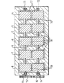
図面を参照すると、入口(図示せず)及び出口(図示せず)を形成したポンプ本体1を有する5段真空ポンプを示す。
入口と出口との間には5つのポンプ室4、5、6、7、8が位置決めされている。ポンプ本体1内には軸受け11、12及び13、14を介して2本の軸9、10がそれぞれ取り付けられており、軸はポンプ室4、5、6、7の各々を貫通する。
軸9、10はポンプ本体内でそれらの長手方向軸線を中心に反対の回転方向に回転するようになっており、軸9は駆動モータ(図示せず)に連結され、軸10はそれぞれの軸に取付けられたタイミング歯車15、16によって軸9に連結されている。
【0009】
通常は、歯車15、16を収容する歯車箱には潤滑が必要とされるけれども、これはポンプ室4、5、6、7から離しておくことができ、従ってポンプ室は乾いたクリーン状態に保たれる。
各軸9、10には5つのロータが取り付けられ、該ロータは、各軸からの1つのロータが各ポンプ室4、5、6、7、8内に置かれるように位置決めされる。ポンプ入口に最も近いポンプ室4内のロータ17及びポンプ出口に最も近いポンプ室8内のロータ18はすべて「ルーツ」型輪郭のものであり、これに対して中間のポンプ室5、6、7はすべて「クロー」型輪郭のものである。
各ポンプ室4、5、6、7、8内のロータ対はそれらのそれぞれの軸に位置決めされ、そしてロータ対が特に真空ポンプについてそれ自体周知の方法でかみ合って作用することができるようにポンプ室内にポンプ室壁に対して位置決めされる。
【0010】
ポンプの使用中、ポンプは荒引きの時少ない電力を使用し、一般的な使用中排気脈動や騒音が小さいことが分かった。
【図面の簡単な説明】
【図1】本発明のポンプの断面を概略的に示す。
【符号の説明】
1 ポンプ本体
4 ポンプ室
5 ポンプ室
6 ポンプ室
7 ポンプ室
8 ポンプ室
9 軸
10 軸
17 ロータ
18 ロータ
19 ロータ[0001]
[Field of the Invention]
The present invention relates to a vacuum pump, and more particularly to a multi-stage oil-free (dry) vacuum pump.
[0002]
[Prior art]
Vacuum pumps that are free of oil in the vacuum chamber and are therefore useful in clean environments such as those found in the semiconductor industry are well known, and in the semiconductor industry, the lubricant present in the vacuum chamber causes contamination.
Such a dry vacuum pump is usually a multistage positive displacement pump that uses a meshing rotor in each vacuum chamber. The rotor has the same type of contour in each vacuum chamber, or the contour varies from one vacuum chamber to another.
The vacuum pump advantageously has a first vacuum adjacent to the pump inlet that houses a pair of “roots” shaped rotors (only two lobes are shown, but two, three or four lobe rotors may be used). A chamber, another vacuum chamber adjacent to the pump outlet, which houses a pair of “claw” type rotors, and a further vacuum chamber intermediate the two cholera vacuum chambers, which also houses a pair of “claw” type rotors; -Wycliffe of our Edwards High Vacuum International Division of J. Vac Sci Technol A 5 (4) in July / August 1987 See the article by (the contents of which are incorporated herein).
[0003]
Such a device has a good combination of properties, i.e. a "root" profile combined with the ability of a "claw" profile chamber to discharge to the atmosphere at the pump outlet against high pressure differences when discharging at low pressure differences Such devices have been widely used in practice in that they show effective and high volumetric efficiency from the chamber, especially in the pressure range of 0.001 to 10 mbar.
[0004]
[Problems to be solved by the invention]
However, vacuum pumps that contain such mixed rotor profiles have certain disadvantages. One drawback is the fact that the pump receives high power consumption in the roughing mode at the start of exhaust. Another drawback is the noise caused in particular by the claw contour rotor in the room adjacent to the pump outlet, which drives the discontinuous trap volume of the exhausted gas into the atmosphere from between the claw rotors in a manner known per se. is there.
It has now been found that such multi-stage different contour pumps can be further improved by selecting a new special combination of contours in different pump chambers.
[0005]
[Means for Solving the Problems]
According to the present invention, each of at least three pump chambers is provided with a pair of meshed rotors, and each pair of first rotors is rotatably attached to a first shaft passing through the pump chamber, A second rotor is rotatably mounted on a second shaft that passes through the pump chamber, and the gas pumped between the pump inlet and the pump outlet is successively pumped by a pair of rotors in each pump chamber. To this end, a device for driving the shaft in the opposite rotational direction is provided, wherein the pump has at least one pump chamber with a “claw” type contour rotor, and at least one pump chamber with a “roots” type contour rotor; And the pump chamber closest to the pump outlet has a “roots” shaped contour rotor.
[0006]
It has been found that an advantage of the “roots” last stage pump of the present invention is that the pulsation frequency is much higher than that of the “claw” stage. For example, in a five-lobe “roots” contour, the pulsation frequency is 10 times the pulsation frequency of the “claw” contour. As a result, the downstream piping is unlikely to vibrate. This allows the pump to operate without the need for an external silencer.
A further advantage of the pump of the present invention is that during roughing the Roots stage can drain the excess pressure generated by the previous “claw” stage more efficiently. Preferably, the pump chamber closest to the pump inlet also has a “roots” shaped contour rotor, which generally provides almost the overall advantages of the pumps mentioned in the above Wycliffe article without the disadvantages mentioned above. Because. Thus, in such an embodiment with a three-stage pump, the pump chamber is between the pump inlet and the pump outlet: (1) a “roots” rotor profile chamber, (2) a “claw” rotor profile chamber and (3 A) "Roots" type rotor profile chamber.
[0007]
Pump of the present invention advantageously have at least four of the pump chamber, ideally, the pump chamber adjacent to the pump inlet, and has a "Roots" -type profile rotors in the pump chamber adjacent the pump outlet In the middle chamber, it has a “claw” shaped contour rotor. Even preferably 4 or more stages of the pump, the pump chamber adjacent the pump inlet and the pump chamber adjacent the pump outlet has "Roots" type profile rotors, with all intermediate pumping chamber "Claw" type profile rotors .
[0008]
DETAILED DESCRIPTION OF THE INVENTION
For a better understanding of the present invention, reference is made by way of example only to the accompanying drawings, which schematically show a cross-section of the pump of the present invention.
Referring to the drawings, a five-stage vacuum pump having a pump body 1 with an inlet (not shown) and an outlet (not shown) is shown.
Five pump chambers 4, 5, 6, 7, and 8 are positioned between the inlet and the outlet. Two
The
[0009]
Normally, the gearbox containing the
Each
The rotor pairs in each pump chamber 4, 5, 6, 7, 8 are positioned on their respective axes and pumps so that the rotor pairs can engage and act in a manner known per se, especially for vacuum pumps. The chamber is positioned relative to the pump chamber wall.
[0010]
During the use of the pump, it was found that the pump uses less power during roughing, and the exhaust pulsation and noise during general use are small.
[Brief description of the drawings]
FIG. 1 schematically shows a cross section of a pump according to the invention.
[Explanation of symbols]
DESCRIPTION OF SYMBOLS 1 Pump main body 4 Pump chamber 5 Pump chamber 6 Pump chamber 7 Pump chamber 8 Pump chamber 9
Claims (4)
Applications Claiming Priority (2)
| Application Number | Priority Date | Filing Date | Title |
|---|---|---|---|
| GBGB9604486.2A GB9604486D0 (en) | 1996-03-01 | 1996-03-01 | Improvements in vacuum pumps |
| GB9604486:2 | 1996-03-01 |
Publications (2)
| Publication Number | Publication Date |
|---|---|
| JPH09317672A JPH09317672A (en) | 1997-12-09 |
| JP3961605B2 true JP3961605B2 (en) | 2007-08-22 |
Family
ID=10789757
Family Applications (1)
| Application Number | Title | Priority Date | Filing Date |
|---|---|---|---|
| JP04314997A Expired - Lifetime JP3961605B2 (en) | 1996-03-01 | 1997-02-27 | Improvement of vacuum pump |
Country Status (5)
| Country | Link |
|---|---|
| US (1) | US5846066A (en) |
| EP (1) | EP0793021B1 (en) |
| JP (1) | JP3961605B2 (en) |
| DE (1) | DE69726630T2 (en) |
| GB (1) | GB9604486D0 (en) |
Families Citing this family (7)
| Publication number | Priority date | Publication date | Assignee | Title |
|---|---|---|---|---|
| US6123526A (en) * | 1998-09-18 | 2000-09-26 | Industrial Technology Research Institute | Multistage pump and method for assembling the pump |
| JP2004536988A (en) * | 2000-10-18 | 2004-12-09 | レイボルド バクーム ゲゼルシャフト ミット ベシュレンクテル ハフトゥング | Multi-stage spiral screw rotor |
| US7682139B2 (en) * | 2007-01-04 | 2010-03-23 | Thomas Matthew Riley | Motor and method of operating the same |
| DE102007020914A1 (en) * | 2007-05-04 | 2008-11-06 | GM Global Technology Operations, Inc., Detroit | Front body for a motor vehicle |
| US7799272B2 (en) | 2007-05-16 | 2010-09-21 | Buffalo Bioblower Technologies Llc | Decontamination methods of use thereof |
| GB0907298D0 (en) * | 2009-04-29 | 2009-06-10 | Edwards Ltd | Vacuum pump |
| EP2439411B1 (en) * | 2010-10-06 | 2017-08-23 | LEONARDO S.p.A. | Pump assembly, in particular for helicopter lubrication |
Family Cites Families (6)
| Publication number | Priority date | Publication date | Assignee | Title |
|---|---|---|---|---|
| USRE25567E (en) * | 1964-05-05 | Lorenz | ||
| GB2111126A (en) * | 1981-12-09 | 1983-06-29 | British Oxygen Co Ltd | Rotary positive-displacement fluid-machines |
| EP0290662B1 (en) * | 1987-05-15 | 1993-03-31 | Leybold Aktiengesellschaft | Positive-displacement two-shaft vacuum pump |
| EP0290663B1 (en) * | 1987-05-15 | 1993-08-04 | Leybold Aktiengesellschaft | Single or multistage two-shaft vacuum pump |
| GB8808608D0 (en) * | 1988-04-12 | 1988-05-11 | Boc Group Plc | Dry pump with booster |
| JP2691168B2 (en) * | 1988-09-05 | 1997-12-17 | 株式会社宇野澤組鐵工所 | Reverse-flow cooling multi-stage rotary vacuum pump with built-in cooling water channel |
-
1996
- 1996-03-01 GB GBGB9604486.2A patent/GB9604486D0/en active Pending
-
1997
- 1997-02-27 DE DE69726630T patent/DE69726630T2/en not_active Expired - Lifetime
- 1997-02-27 JP JP04314997A patent/JP3961605B2/en not_active Expired - Lifetime
- 1997-02-27 US US08/807,513 patent/US5846066A/en not_active Expired - Lifetime
- 1997-02-27 EP EP97301342A patent/EP0793021B1/en not_active Expired - Lifetime
Also Published As
| Publication number | Publication date |
|---|---|
| DE69726630D1 (en) | 2004-01-22 |
| DE69726630T2 (en) | 2004-09-23 |
| US5846066A (en) | 1998-12-08 |
| GB9604486D0 (en) | 1996-05-01 |
| EP0793021B1 (en) | 2003-12-10 |
| EP0793021A1 (en) | 1997-09-03 |
| JPH09317672A (en) | 1997-12-09 |
Similar Documents
| Publication | Publication Date | Title |
|---|---|---|
| US8702407B2 (en) | Multistage roots vacuum pump having different tip radius and meshing clearance from inlet stage to exhaust stage | |
| US5667370A (en) | Screw vacuum pump having a decreasing pitch for the screw members | |
| KR100647012B1 (en) | Roots rotor and screw rotor combined dry vacuum pump | |
| JP2001207984A (en) | Vacuum exhaust device | |
| US4504201A (en) | Mechanical pumps | |
| JP2005155540A (en) | Multistage dry-sealed vacuum pump | |
| GB2088957A (en) | Rotary positive-displacement Fluid-machines | |
| JP3961605B2 (en) | Improvement of vacuum pump | |
| GB2111126A (en) | Rotary positive-displacement fluid-machines | |
| JPH0230989A (en) | Vacuum pump device | |
| JP2004263629A (en) | Screw vacuum pump | |
| JP3992176B2 (en) | Vacuum exhaust method and vacuum exhaust device | |
| EP1006281A1 (en) | Multi-stage roots pump | |
| US6129534A (en) | Vacuum pumps | |
| US6379135B2 (en) | Vacuum pumps | |
| EP0965758A2 (en) | Vacuum pump | |
| CN110770444B (en) | Multi-stage rotary piston pump | |
| US10533552B2 (en) | Rotary screw vacuum pumps | |
| GB2065776A (en) | Rotary-piston Fluid-machines | |
| JP2007263122A (en) | Vacuum exhaust device | |
| CN114144572A (en) | Pumping unit | |
| WO2005040614A1 (en) | Multistage vacuum pump with improved efficiency | |
| JP2002174175A (en) | Vacuum exhaust device | |
| JP2005256845A (en) | Vacuum exhaust device | |
| JP2007263121A (en) | Vacuum exhaust device |
Legal Events
| Date | Code | Title | Description |
|---|---|---|---|
| A131 | Notification of reasons for refusal |
Free format text: JAPANESE INTERMEDIATE CODE: A131 Effective date: 20061120 |
|
| A521 | Written amendment |
Free format text: JAPANESE INTERMEDIATE CODE: A523 Effective date: 20070219 |
|
| TRDD | Decision of grant or rejection written | ||
| A01 | Written decision to grant a patent or to grant a registration (utility model) |
Free format text: JAPANESE INTERMEDIATE CODE: A01 Effective date: 20070501 |
|
| A61 | First payment of annual fees (during grant procedure) |
Free format text: JAPANESE INTERMEDIATE CODE: A61 Effective date: 20070517 |
|
| R150 | Certificate of patent or registration of utility model |
Free format text: JAPANESE INTERMEDIATE CODE: R150 |
|
| FPAY | Renewal fee payment (event date is renewal date of database) |
Free format text: PAYMENT UNTIL: 20100525 Year of fee payment: 3 |
|
| S111 | Request for change of ownership or part of ownership |
Free format text: JAPANESE INTERMEDIATE CODE: R313113 |
|
| FPAY | Renewal fee payment (event date is renewal date of database) |
Free format text: PAYMENT UNTIL: 20100525 Year of fee payment: 3 |
|
| R360 | Written notification for declining of transfer of rights |
Free format text: JAPANESE INTERMEDIATE CODE: R360 |
|
| FPAY | Renewal fee payment (event date is renewal date of database) |
Free format text: PAYMENT UNTIL: 20100525 Year of fee payment: 3 |
|
| FPAY | Renewal fee payment (event date is renewal date of database) |
Free format text: PAYMENT UNTIL: 20100525 Year of fee payment: 3 |
|
| R370 | Written measure of declining of transfer procedure |
Free format text: JAPANESE INTERMEDIATE CODE: R370 |
|
| S111 | Request for change of ownership or part of ownership |
Free format text: JAPANESE INTERMEDIATE CODE: R313113 |
|
| FPAY | Renewal fee payment (event date is renewal date of database) |
Free format text: PAYMENT UNTIL: 20100525 Year of fee payment: 3 |
|
| R350 | Written notification of registration of transfer |
Free format text: JAPANESE INTERMEDIATE CODE: R350 |
|
| FPAY | Renewal fee payment (event date is renewal date of database) |
Free format text: PAYMENT UNTIL: 20110525 Year of fee payment: 4 |
|
| FPAY | Renewal fee payment (event date is renewal date of database) |
Free format text: PAYMENT UNTIL: 20110525 Year of fee payment: 4 |
|
| FPAY | Renewal fee payment (event date is renewal date of database) |
Free format text: PAYMENT UNTIL: 20120525 Year of fee payment: 5 |
|
| FPAY | Renewal fee payment (event date is renewal date of database) |
Free format text: PAYMENT UNTIL: 20130525 Year of fee payment: 6 |
|
| R250 | Receipt of annual fees |
Free format text: JAPANESE INTERMEDIATE CODE: R250 |
|
| R250 | Receipt of annual fees |
Free format text: JAPANESE INTERMEDIATE CODE: R250 |
|
| R250 | Receipt of annual fees |
Free format text: JAPANESE INTERMEDIATE CODE: R250 |
|
| R250 | Receipt of annual fees |
Free format text: JAPANESE INTERMEDIATE CODE: R250 |
|
| S531 | Written request for registration of change of domicile |
Free format text: JAPANESE INTERMEDIATE CODE: R313531 |
|
| R350 | Written notification of registration of transfer |
Free format text: JAPANESE INTERMEDIATE CODE: R350 |
|
| EXPY | Cancellation because of completion of term |