JP3960552B2 - Label form - Google Patents
Label form Download PDFInfo
- Publication number
- JP3960552B2 JP3960552B2 JP2003368912A JP2003368912A JP3960552B2 JP 3960552 B2 JP3960552 B2 JP 3960552B2 JP 2003368912 A JP2003368912 A JP 2003368912A JP 2003368912 A JP2003368912 A JP 2003368912A JP 3960552 B2 JP3960552 B2 JP 3960552B2
- Authority
- JP
- Japan
- Prior art keywords
- cut
- slip
- line
- separation
- contour
- Prior art date
- Legal status (The legal status is an assumption and is not a legal conclusion. Google has not performed a legal analysis and makes no representation as to the accuracy of the status listed.)
- Expired - Lifetime
Links
- 238000000926 separation method Methods 0.000 claims description 53
- 238000009958 sewing Methods 0.000 claims description 48
- 239000010410 layer Substances 0.000 claims description 17
- 239000012790 adhesive layer Substances 0.000 claims description 14
- 239000003795 chemical substances by application Substances 0.000 claims description 14
- 239000000853 adhesive Substances 0.000 claims description 11
- 230000001070 adhesive effect Effects 0.000 claims description 10
- 238000005520 cutting process Methods 0.000 claims description 9
- 239000004820 Pressure-sensitive adhesive Substances 0.000 claims description 5
- 239000003292 glue Substances 0.000 description 6
- 239000011248 coating agent Substances 0.000 description 3
- 238000000576 coating method Methods 0.000 description 3
- 230000000694 effects Effects 0.000 description 3
- 238000004519 manufacturing process Methods 0.000 description 3
- 238000000034 method Methods 0.000 description 3
- 244000043261 Hevea brasiliensis Species 0.000 description 2
- 238000004891 communication Methods 0.000 description 2
- 239000000976 ink Substances 0.000 description 2
- 230000007257 malfunction Effects 0.000 description 2
- 229920003052 natural elastomer Polymers 0.000 description 2
- 229920001194 natural rubber Polymers 0.000 description 2
- 229920003051 synthetic elastomer Polymers 0.000 description 2
- 239000005061 synthetic rubber Substances 0.000 description 2
- NIXOWILDQLNWCW-UHFFFAOYSA-N acrylic acid group Chemical group C(C=C)(=O)O NIXOWILDQLNWCW-UHFFFAOYSA-N 0.000 description 1
- 238000009826 distribution Methods 0.000 description 1
- 238000001035 drying Methods 0.000 description 1
- 229920001971 elastomer Polymers 0.000 description 1
- 239000000203 mixture Substances 0.000 description 1
- 229920001296 polysiloxane Polymers 0.000 description 1
- 239000005060 rubber Substances 0.000 description 1
- 230000009466 transformation Effects 0.000 description 1
- 230000003313 weakening effect Effects 0.000 description 1
Images


Landscapes
- Making Paper Articles (AREA)
- Credit Cards Or The Like (AREA)
Description
本発明は、特に通信販売業界,百貨店業界,運輸業界等で使用される配送伝票として好適なラベル帳票に関する。 The present invention relates to a label form suitable as a delivery slip used particularly in the mail order industry, department store industry, transportation industry, and the like.
例えば注文を受けた通信販売業者が商品を配送する場合、商品の流通を管理する目的で商品を梱包したケースに配送伝票を貼付して発送している。 For example, when a mail order dealer who has received an order delivers a product, the delivery slip is attached to a case in which the product is packed for the purpose of managing the distribution of the product.
配送伝票としては図8に示す構造のものが一般的である。同図に示す配送伝票2は、貼付票2−1,配達票2−2,貼付片2−3の3つの紙片が切り取り線2a,2aを介して隣接され、貼付票2−1と貼付片2−3の裏面に設けられた粘着剤層3でケース1に貼り付ける構造になっている(図8a参照)。そして、配送業者はケース1を配達すると、配送伝票2の配達票2−2に受取人の捺印またはサインをもらい、2本の切り取り線2a,2aを切断し(図8b参照)、配達票2−2を配送伝票2から切り離して配達控えとして持ち帰るものとしている(図8c参照)。
A delivery slip having a structure shown in FIG. 8 is generally used. In the
また、配送伝票の他の例としては図9に示す構造のものも知られている。同図に示す配送伝票4は、貼付票4−1の領域内に配達票4−2が設けられていて、配達票4−2の輪郭をかたどった切り取り線4aが形成され、配達票4−2を除いた貼付票4−1裏面に設けられた粘着剤層5でケース1に貼り付ける構造になっている(図9a参照)。
As another example of the delivery slip, a structure shown in FIG. 9 is also known. In the delivery slip 4 shown in the figure, a delivery slip 4-2 is provided in the area of the sticky slip 4-1, and a
さらに、特許文献1には、上質紙からなる上紙と、上質紙の裏面に粘着剤を介して剥離紙を貼り合わせたタック紙とで構成された配送用帳票が開示されている。この配送用帳票は上紙に配送伝票部と通信シート部がハーフカット線を介して隣接され、上紙の裏面に擬似接着剤を介してタック紙が貼着された構造になっている。
Furthermore,
例示した従来の配送伝票によると以下のような問題点が指摘されている。 According to the conventional delivery slip illustrated, the following problems are pointed out.
例えば、図8cに示すように、配達票2−2を切り離した後には貼付票2−1と貼付片2−3がケース1に貼り付いたまま残り、剥がした配達票2−2部分が欠落してケース1の地肌が露出するので、外観上決して見栄えの良いものではない。また、剥がした配達票2−2は配達業者に持ち帰られてしまうので、配達票2−2には受取人に伝達したい情報を載せることができず、配送伝票2に掲載できる情報量が少ないという欠点もある。
For example, as shown in FIG. 8c, after the delivery slip 2-2 is cut off, the sticky slip 2-1 and the sticking piece 2-3 remain attached to the
また、図9bに示すように、配達票4−2を斜め方向に無理に剥がそうとすると切り取り線4aから外れてしまい、配達票4−2が途中で破損することがある。そこで、この配達票4−2を貼付票4−1から切り離し易くするために、図9cに示すようなミシン線を粗く(カット部を大きく)した切り取り線4bを形成した場合、今度は配達時にケース1を積み重ねるなどして外力が加えられると切り取り線4bが簡単にハチケてしまい、配達票4−2が配送伝票4から脱落するという不具合もある。
Further, as shown in FIG. 9b, if the delivery slip 4-2 is forcibly peeled off in an oblique direction, the delivery slip 4-2 may be detached from the
さらに、特許文献1に開示された配送用帳票の場合には、通信シート部に別途情報を載せることができるという利点があるものの、上紙の裏面に貼着するタック紙が高価なため帳票の作製コストが嵩むという欠点がある。また、上紙の裏面に上質紙,粘着剤,剥離紙という3層構造からなるタック紙を擬似接着剤で貼着する構造であるので、帳票の総厚が厚くなってトナーの定着性が悪い上に、帳票の腰が強くなり過ぎてしまいプリンタでの通紙性に支障を来たすという不具合がある。
Furthermore, in the case of the delivery form disclosed in
本発明は、このような事情に鑑みてなされたもので、その目的とするところは、外観見栄えが良好で掲載できる情報量も多く、かつ帳票の総厚を抑えてプリンタでの印字適性に優れたラベル帳票を提供することにある。 The present invention has been made in view of such circumstances, and the purpose of the present invention is to have a good appearance and a large amount of information that can be posted, and to suppress the total thickness of the form and to be excellent in printability on a printer. Is to provide a label form.
本発明は、上記の目的を達成するため、台紙上に上紙が剥離可能に貼合された帳票であって、上紙は、本票と分離票とが輪郭切り取り線で隣接された伝票片を備え、かつ分離票を除いた裏面領域に粘着剤を塗工した粘着剤層が設けられてなるとともに、台紙は、粘着剤層と対向する表面領域に剥離剤を塗工した剥離剤層が設けられ、かつ台紙裏面から台紙表面まで到達する深さの切り込みであって輪郭切り取り線を囲んで分離票よりも大きな輪郭を有する輪郭ハーフカット線が形成され、輪郭ハーフカット線よりも内側の表面領域に情報記載欄を備えてなり、伝票片裏面の台紙をめくって輪郭ハーフカット線を切断し、輪郭ハーフカット線の内側部分を残した状態で上紙から台紙を剥がし取ると伝票片を被着体に貼付でき、輪郭切り取り線を切断して本票から分離票を切り離すと分離票に相当する部位に台紙の情報記載欄が現れるようになっていることを特徴とするラベル帳票を提供するものである。 In order to achieve the above object, the present invention is a form in which an upper sheet is detachably bonded on a mount, and the upper sheet is a slip piece in which the main sheet and a separation sheet are adjacent to each other by a contour cut line. the provided, and the pressure-sensitive adhesive layer was applied an adhesive on the back surface region excluding the separation votes is provided such Rutotomoni, mount, the release agent layer was coated with a release agent to the surface area facing the pressure-sensitive adhesive layer is provided, and is formed contour half-cut line having a larger contour than the separation form an in cut depth that reaches from the mount back surface to mount the surface surrounding the contour cut line, inner than the contour half-cut line An information entry field is provided on the front surface area, the contour half-cut line is cut by turning the backing on the back side of the slip piece, and the slip piece is removed from the top sheet with the inner part of the contour half-cut line remaining. Can be affixed to the adherend and has a contour cut line There is provided a label form which is characterized that the cross-sectional and made by the present form as information description column mount the portion corresponding to the separation form disconnecting the separation votes appear.
ここで、この発明において使用する台紙と上紙は、ともにレーザプリンタやインクジェットプリンタ等のノンインパクトプリンタや、熱転写プリンタあるいはドットインパクトプリンタ等による印字適性を備えた印刷用紙で構成されていることが好ましい。例えば上質紙,軽量コート紙,コート紙,アート紙等が使用でき、この中でも印字適性に優れた上質紙が好適である。 Here, both the mount and the upper paper used in the present invention are preferably composed of printing paper having printability by a non-impact printer such as a laser printer or an inkjet printer, a thermal transfer printer or a dot impact printer. . For example, high-quality paper, lightweight coated paper, coated paper, art paper, and the like can be used. Among these, high-quality paper having excellent printability is preferable.
粘着剤層は、例えばアクリル系糊,ゴム系の天然ゴム糊,合成ゴム糊,あるいは天然ゴム糊と合成ゴム糊を混ぜ合わせた糊などの各種の糊類を用紙上に塗工することで形成でき、剥離剤層は、例えば主成分にシリコーン等の離型剤が含有された各種の紫外線硬化型インキを用紙上に印刷して乾燥させることで形成できる。 The adhesive layer is formed by applying various types of glue on the paper, such as acrylic glue, rubber-based natural rubber glue, synthetic rubber glue, or a mixture of natural rubber glue and synthetic rubber glue. The release agent layer can be formed by, for example, printing various ultraviolet curable inks containing a release agent such as silicone as a main component on paper and drying the ink.
さらに、切り取り線とは、用紙にカット部とアンカット部を形成したミシン線のようにカッター等の刃具を使用しなくても用紙を切断できるようにした線のことをいい、ハーフカット線とは、用紙の厚み方向にかけてその用紙を完全には切断してしまわない深さの切り込みを入れた線のことをいう。 Furthermore, the cut line is a line that allows cutting of paper without using a cutter such as a cutter, such as a machine line in which a cut part and an uncut part are formed on a paper. Means a line having a depth of cut that does not completely cut the sheet in the thickness direction of the sheet.
本発明のラベル帳票は台紙の上に上紙を貼合した構成であるので、帳票の総厚を薄く抑えることで安定したトナー定着性が得られ、帳票の腰が強くなり過ぎずプリンタでの通紙性を良好に維持できる。またハーフカット線の内側部分を残したまま台紙を上紙から剥がして帳票を貼り付けることで、分離票を切り離した部分に台紙の情報記載欄が現れて帳票の外観見栄えを良好に保つことができ、かつ帳票上に更なる情報を掲載することが可能になる。 Since the label form of the present invention has a structure in which an upper sheet is pasted on a mount, stable toner fixing properties can be obtained by keeping the total thickness of the form thin, and the form does not become too stiff. The paper passing property can be maintained well. Also, by peeling off the backing sheet from the top sheet while leaving the inner part of the half-cut line, and pasting the form, an information entry field on the backing sheet appears in the part where the separating form is separated, and the appearance of the form can be kept good. And more information can be posted on the form.
また、本発明の一実施態様として、前記輪郭切り取り線は、カット部とアンカット部を有する通常ミシン線と、通常ミシン線のアンカット部に設けられたカット部とアンカット部を有するマイクロミシン線とからなる混合ミシン線であると良い。 As one embodiment of the present invention, the contour cut line includes a normal sewing line having a cut portion and an uncut portion, and a micro sewing machine having a cut portion and an uncut portion provided in the uncut portion of the normal sewing line. It is good that it is a mixed sewing line composed of a line.
ここで、マイクロミシン線とは、カット部とアンカット部の長さがそれぞれ1.0mm以下に設定されたミシン線のことを指し、カット部とアンカット部の長さがそれぞれ1.0mmを超えるミシン線は通常ミシン線と定義する。 Here, the micro sewing machine line refers to a sewing machine line in which the length of the cut part and the uncut part is set to 1.0 mm or less, and the length of the cut part and the uncut part is 1.0 mm respectively. The exceeding sewing line is usually defined as a sewing line.
この構成によると、分離票の輪郭の途中に切断しにくいマイクロミシン線が点在することで通常ミシン線の切断が食い止められて配達時における分離票の脱落を防止でき、かつ分離票の輪郭の途中に切断し易い通常ミシン線が点在することで分離票の分離時には大きな力を必要とせずにミシン線の切断をスムーズに行うことができるという利点がある。 According to this configuration, the micro-sewing lines that are difficult to cut are scattered in the middle of the outline of the separation sheet, so that the cutting of the normal sewing machine line is prevented, and the separation sheet can be prevented from falling off during delivery. The fact that normal sewing lines that are easy to cut in the middle are dotted, there is an advantage that the sewing line can be cut smoothly without requiring a large force when separating the separation slip.
本発明に係るラベル帳票によると、台紙上に上紙を貼合した構成であり、帳票の総厚を薄くできかつ帳票の腰が強くなり過ぎないので、安定したトナー定着性が得られるとともにプリンタでの通紙性を良好に維持できるという効果を有する。 According to the label form according to the present invention, the upper sheet is laminated on the mount, the total thickness of the form can be reduced, and the form does not become too stiff, so that stable toner fixing property can be obtained and the printer This has the effect that the paper-passing property can be maintained well.
また、高価なタック紙を貼着する構成でもないため、作製コストを低減できるという効果を有する。 Moreover, since it is not the structure which sticks expensive tack paper, it has the effect that production cost can be reduced.
さらに、切り離される分離票の部分に台紙を残したまま帳票を貼り付けることができるので、分離票を剥がした後の帳票の外観見栄えを向上させることができるとともに帳票上に更なる情報を掲載できるという効果を有する。 In addition, since the form can be pasted while leaving the mount on the part of the separation form to be separated, the appearance of the form after the separation form is removed can be improved and further information can be posted on the form. It has the effect.
以下、本発明の実施の形態について、添付図面を参照しながら詳細に説明する。 Hereinafter, embodiments of the present invention will be described in detail with reference to the accompanying drawings.
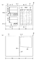
図1に示すように、本実施形態のラベル帳票Pは、通信販売業者や百貨店業者が商品を配送する際に、商品を梱包したケースに貼り付けて商品管理を行う配送伝票として使用される。このラベル帳票Pは、上質紙を使用した上紙11−1と、同じく上質紙を使用した台紙11−2を重ね合わせて貼合したシート体11で構成されており、シート体11上に伝票片P1と帳票片P2を備えている。
As shown in FIG. 1, the label form P of the present embodiment is used as a delivery slip that is attached to a case in which products are packed and managed by a mail order dealer or a department store dealer when the products are delivered. This label form P is composed of an upper sheet 11-1 using high-quality paper and a
図2に示すように、上紙11−1は矩形状に成形され、その略中央部分を縦断して上紙表面から上紙裏面まで到達する深さの境界切り取り線12が形成されている。上紙11−1は境界切り取り線12を介して伝票片P1と帳票片P2が分割可能に隣接されている。
As shown in FIG. 2, the upper paper 11-1 is formed in a rectangular shape, and a
伝票片P1はさらに本票P11と分離票P12の2つの伝票に区画され、本票P11が配送伝票の貼付票に、分離票P12が配送伝票の配達票になる。つまり分離票P12の周囲は輪郭切り取り線13で囲まれていて、この輪郭切り取り線13を切断することで本票P11から分離票P12が切り離される。上紙11−1の裏面側には、この分離票P12を除いた領域に粘着剤層15が全面塗工されている(図2b参照)。
The slip piece P1 is further divided into two slips, a main slip P11 and a separation slip P12. The main slip P11 becomes a delivery slip sticker and the separation slip P12 becomes a delivery slip delivery slip. That is, the periphery of the separation slip P12 is surrounded by the
また、分離票P12にはその角部を切り落として輪郭切り取り線13に繋がるコーナーカット部14が形成されていて、分離票P12の端部を摘まんで輪郭切り取り線13を切断し易くなっており、分離票P12の破損を防ぐことができる。
Further, a
さらに、輪郭切り取り線13の形状としては図3に示すような特殊形状のミシン線を採用している。このミシン線は通常ミシン線13−1と、通常ミシン線13−1よりもピッチの細かなマイクロミシン線13−2とからなる混合ミシン線である。
Further, as the shape of the
本実施形態では、分離票P12の大きさが縦94mm,横100mmの矩形状に成形されていて、通常ミシン線13−1とマイクロミシン線13−2の長さはそれぞれ次のように設定されている。通常ミシン線13−1はカット部13−1aとアンカット部13−1bで構成されており、カット部13−1aの長さが7.0mm,アンカット部13−1bの長さが4.0mmに設定されている。マイクロミシン線13−2は通常ミシン線13−1のアンカット部13−1b上に設けられたカット部13−2aとアンカット部13−2bで構成されており、カット部13−2aの長さが1.0mm以下,アンカット部13−2bの長さが0.6mm以下で、かつ両者を組み合わせたミシン線全体の長さが2.0〜4.0mmの範囲内に設定されている。 In this embodiment, the size of the separation sheet P12 is formed in a rectangular shape with a length of 94 mm and a width of 100 mm, and the lengths of the normal sewing machine line 13-1 and the micro sewing machine line 13-2 are set as follows. ing. Usually, the sewing machine line 13-1 includes a cut portion 13-1a and an uncut portion 13-1b. The length of the cut portion 13-1a is 7.0 mm and the length of the uncut portion 13-1b is 4. It is set to 0 mm. The micro-sewing line 13-2 is generally composed of a cut part 13-2a and an uncut part 13-2b provided on the uncut part 13-1b of the sewing machine line 13-1, and the length of the cut part 13-2a. Is 1.0 mm or less, the length of the uncut portion 13-2 b is 0.6 mm or less, and the total length of the sewing machine line combining both is set in the range of 2.0 to 4.0 mm. .
なお、コーナーカット部14を除く分離票P12の隅部は1.0mmのカット部になっている。
Note that the corner of the separation sheet P12 excluding the corner cut
このように、輪郭切り取り線13の形状として通常ミシン線13−1とマイクロミシン線13−2を交互に配置した混合ミシン線を採用したのは次のような理由による。
As described above, the mixed sewing line in which the normal sewing line 13-1 and the micro sewing line 13-2 are alternately arranged is adopted as the shape of the
すなわち、輪郭切り取り線13を通常ミシン線のようにカット部が大きなミシン線のみで構成すると、小さな外力が加えられただけで輪郭切り取り線13が簡単にハチケてしまい、分離票P12が本票P11から脱落することがある。逆に輪郭切り取り線13をマイクロミシン線のようにカット部が小さなミシン線のみで構成すると、輪郭切り取り線13を切断するために大きな力が必要になり、無理に剥がそうとするとミシン線から外れてしまい、分離票P12が破損することがある。
That is, if the
これに対して、本実施形態のように輪郭切り取り線13に混合ミシン線を採用することで、分離票P12の輪郭の途中にマイクロミシン線13−2が点在することになり、通常ミシン線13−1がハチケてもマイクロミシン線13−2でそれ以上の切断が食い止められるので、配達時における分離票P12の脱落を防止できる。加えて、分離票P12の輪郭の途中には通常ミシン線13−1も点在するので、分離票P12の分離時には大きな力を加えなくてもミシン線の切断をスムーズに行うことができる。
On the other hand, by using a mixed sewing line as the
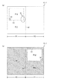
図4に示すように、台紙11−2は上紙11−1と等しい大きさに成形され、上紙11−1の境界切り取り線12に相当する位置には通常ミシン線で形成された境界切り取り線26が設けられている。台紙11−2はこの境界切り取り線26を介して伝票片P1と帳票片P2が分割可能に隣接されている。
As shown in FIG. 4, the mount 11-2 is formed to have the same size as the upper paper 11-1, and a boundary cut formed by a normal sewing machine line at a position corresponding to the boundary cut
また、このラベル帳票Pでは、上紙11−1と台紙11−2を貼り合わせたときに上紙11−1の境界切り取り線12と台紙11−2の境界切り取り線26とが互いにずれてしまった場合であっても、伝票片P1と帳票片P2との分離作業が確実に行われるようにしてある。すなわち、境界切り取り線26に沿って略0.5mm程度ずらした位置に台紙11−2の裏面から表面まで到達する深さの切り込みを形成した境界ハーフカット線27が設けられている。境界切り取り線26と境界ハーフカット線27は、そのいずれか一方が設けられていれば良く、またその双方が設けられていても構わない。なお、上紙11−1と台紙11−2を貼り合わせた後に境界切り取り線12を形成する作製手順を採用した場合には、上紙11−1と台紙11−2において切り取り線がずれることはないので境界ハーフカット線27は必ずしも必要ではなくなる。
Further, in this label form P, when the upper paper 11-1 and the mount 11-2 are bonded, the boundary cut
台紙11−2の伝票片P1には、分離票P12の外形寸法よりも大きな輪郭を持つ輪郭ハーフカット線23が設けられている。すなわち、この輪郭ハーフカット線23は、上紙11−1の輪郭切り取り線13を囲んで台紙11−2裏面から台紙11−2表面まで到達する深さの切り込みを形成したものである。また、台紙11−2の表面側には、上紙11−1の粘着剤層15と対向する部位、つまり分離票P12を除いた領域に剥離剤層25が塗工されている。この剥離剤層25は、上紙11−1の裏面に塗工された粘着剤層15との接着力を弱めて上紙11−1から台紙11−2を剥がし易くするためのものである。
On the slip piece P1 of the mount 11-2, a contour half-
なお、上紙11−1から台紙11−2を剥がし易くする手段としては、図6に示すように、上紙11−1裏面にある粘着剤層15の塗工パターンを全面塗工に替えて点糊状に塗工して、粘着剤層15の接着力を減少させることも考えられる。
As a means for facilitating the peeling of the mount 11-2 from the upper paper 11-1, as shown in FIG. 6, the coating pattern of the
このように構成された台紙11−2の上に上紙11−1を重ね合わせて加圧すると、上紙11−1と台紙11−2との用紙間の構造は図5のようになる。 When the upper paper 11-1 is superposed on the mount 11-2 configured as described above and pressed, the structure between the upper paper 11-1 and the mount 11-2 is as shown in FIG.
伝票片P1の本票P11では、上紙11−1裏面に塗工された粘着剤層15と台紙11−2表面に塗工された剥離剤層25が接触して、上紙11−1と台紙11−2が剥離可能に接着される。一方、伝票片P1の分離票P12では、上紙11−1裏面に粘着剤層15が塗工されていないので、台紙11−2の上に上紙11−1が重なっただけの状態になっている(図5a参照)。
In the slip P11 of the slip piece P1, the
帳票片P2では、上紙11−1裏面に塗工された粘着剤層15と台紙11−2表面に塗工された剥離剤層25が接触して、上紙11−1と台紙11−2が剥離可能に接着された状態になっている(図5b参照)。
In the form piece P2, the
このような構成からなるラベル帳票Pは、例えば商品管理を行うための配送伝票と、商品の明細票を一体化した帳票として使用できる。図1aに示すように、伝票片P1が配送伝票になり、本票P11と分離票P12にはそれぞれ配送先,配送元,商品名の他に配達指定日や配達時間帯などの配送情報を記載する伝票記載欄16が印刷される。また図1bに示すように、帳票片P2が明細票になり、明細票には商品番号,商品名,数量,金額などの商品情報を記載する帳票記載欄17が印刷される。
The label form P having such a configuration can be used, for example, as a form in which a delivery slip for managing a product and a product statement form are integrated. As shown in FIG. 1a, the slip piece P1 becomes a delivery slip, and in this slip P11 and separation slip P12, delivery information such as a delivery specified date and a delivery time zone is described in addition to a delivery destination, a delivery source, and a product name. The
さらに図4aに示すように、台紙11−2の分離票P12に相当する部位には、受取人に伝達したい情報があらかじめ情報記載欄18に印刷される。なお、この情報記載欄18は配達時には分離票P12によって隠蔽されているので秘匿情報を記載することも可能である。
Further, as shown in FIG. 4a, information desired to be transmitted to the recipient is printed in advance in the
続いて、本実施形態のラベル帳票の使用方法を説明する。 Next, a method for using the label form according to this embodiment will be described.
まず、商品の注文を受けた通信販売業者や百貨店業者は、図7aに示すように伝票片P1の伝票記載欄16と帳票片P2の帳票記載欄17にそれぞれ所定事項を各種プリンタで印刷処理する。所定事項が印刷されたラベル帳票Pは、配送する商品とともに配送業者に委託される。
First, as shown in FIG. 7A, a mail-order dealer or department store dealer who has received an order for a product prints predetermined items in the
次に、配送業者は、図7bに示すように帳票記載欄17に記載された所定事項を確認して、境界切り取り線12を切断して伝票片P1と帳票片P2とを切り離す。ここで台紙11−2の裏面側には境界切り取り線12に相当する位置に境界切り取り線26と境界ハーフカット線27が形成されているので、上紙11−1と台紙11−2が破損することなく伝票片P1と帳票片P2を互いに分離できる。
Next, the delivery company confirms the predetermined items described in the
次いで、配送業者は、図7cに示すように伝票片P1裏面の台紙11−2をめくって輪郭ハーフカット線23を切断し、輪郭ハーフカット線23の内側部分を残して台紙11−2を上紙11−1から剥がす。ここで台紙11−2は剥離剤層25によって粘着力が弱められているので、上紙11−1の粘着剤層15から無理なく剥がすことができる。
Next, as shown in FIG. 7c, the delivery company turns the mount 11-2 on the back side of the slip piece P1 to cut the contour half-
さらに、図7dに示すように、裏面に露出した粘着剤層15によって伝票片P1を商品梱包済みのケース1の外側に貼り付ける。この状態でケース1が配達される。貼り付けられた伝票片P1において、分離票P12の輪郭切り取り線13には切断しにくいマイクロミシン線13−2が含まれているので、配達時に輪郭切り取り線13に外力が加えられても分離票P12が切り離されて脱落することはない。
Further, as shown in FIG. 7d, the slip piece P1 is attached to the outside of the
配送業者はケース1を配達すると、伝票片P1の分離票P12に受取人の捺印またはサインをもらう。そして、図7eに示すように分離票P12のコーナーカット部14に指を掛け分離票P12の端部を摘まんで輪郭切り取り線13を切断し、分離票P12を本票P11から分離して配達控えとして持ち帰る。ここで分離票P12には粘着剤層15が塗工されておらず台紙11−2上に重なっているだけなので、台紙11−2から簡単に切り離すことができる。また、輪郭切り取り線13には上述したように切断し易い通常ミシン線13−1が含まれているので、本票P11と分離票P12を互いに破損することなく分離できる。
When delivering the
分離票P12を切り離した後のケース1は、図7fに示すように分離票P12下面に台紙11−2が残った状態になるので、図8cに示した配送伝票2のように分離票2−2部分が欠落してケース1の地肌部分が露出してしまうものに比べて分離後の外観見栄えを向上させることができる。また台紙11−2の分離票P12に相当する部位には、分離票P12を切り離すことによって情報記載欄18が現れるため、受取人に更なる情報を伝達することも可能である。
In
以上、本発明の実施形態を説明したが、上述した実施形態においては様々な変形が可能である。例えば、ラベル帳票Pの帳票片P2は、上紙11−1裏面の粘着剤層15と台紙11−2表面の剥離剤層25で剥離可能に接着したラベル形態になっているが、必要に応じて台紙11−2表面の剥離剤層25をなくして上紙11−1と台紙11−2を剥離不能に完全接着する構成を採用しても良い。また、ラベル帳票Pは印刷用紙からなる上紙11−1と台紙11−2を貼合したシート体11で構成されているため、台紙11−2裏面にもプリンタでの印字が可能であり、台紙11−2裏面にある余白スペースに更なる情報を印刷することもできる。
As mentioned above, although embodiment of this invention was described, various deformation | transformation are possible in embodiment mentioned above. For example, the form piece P2 of the label form P is in the form of a label that is detachably bonded with the
P ラベル帳票
P1 伝票片
P11 本票
P12 分離票
P2 帳票片
11 シート体
11−1 上紙
11−2 台紙
12 境界切り取り線
13 輪郭切り取り線
13−1 通常ミシン線
13−1a カット部
13−1b アンカット部
13−2 マイクロミシン線
13−2a カット部
13−2b アンカット部
14 コーナーカット部
15 粘着剤層
16 伝票記載欄
17 帳票記載欄
18 情報記載欄
23 輪郭ハーフカット線
25 剥離剤層
26 境界切り取り線
27 境界ハーフカット線
P label form P1 slip piece P11 main form P12 separation form
Claims (2)
上紙は、本票と分離票とが輪郭切り取り線で隣接された伝票片を備え、かつ分離票を除いた裏面領域に粘着剤を塗工した粘着剤層が設けられてなるとともに、
台紙は、粘着剤層と対向する表面領域に剥離剤を塗工した剥離剤層が設けられ、かつ台紙裏面から台紙表面まで到達する深さの切り込みであって輪郭切り取り線を囲んで分離票よりも大きな輪郭を有する輪郭ハーフカット線が形成され、輪郭ハーフカット線よりも内側の表面領域に情報記載欄を備えてなり、
伝票片裏面の台紙をめくって輪郭ハーフカット線を切断し、輪郭ハーフカット線の内側部分を残した状態で上紙から台紙を剥がし取ると伝票片を被着体に貼付でき、輪郭切り取り線を切断して本票から分離票を切り離すと分離票に相当する部位に台紙の情報記載欄が現れるようになっている
ことを特徴とするラベル帳票。 It is a form in which the top paper is releasably bonded on the mount,
Above paper, the form and comprises a slip piece which is adjacent to the separation form and contour cut line, and the pressure-sensitive adhesive layer was applied an adhesive on the back surface region excluding the separation votes is provided such Rutotomoni,
The backing paper is provided with a release agent layer coated with a release agent in the surface area facing the adhesive layer, and is a depth of cut reaching the backing paper surface from the back side of the backing sheet, surrounding the contour cut line and from the separation slip also formed contour half-cut line having a larger profile, becomes an information description column on the inner surface area than the contour half-cut line,
Turn the backing on the back side of the slip, cut the contour half-cut line, and leave the inner part of the contour half-cut line, and then peel off the backing from the top sheet to attach the slip piece to the adherend. A label form in which an information description column on the mount appears in a portion corresponding to the separation form when the separation form is separated from the present form by cutting .
前記輪郭切り取り線は、カット部とアンカット部を有する通常ミシン線と、通常ミシン線のアンカット部に設けられたカット部とアンカット部を有するマイクロミシン線とからなる混合ミシン線である
ことを特徴とするラベル帳票。 In the label form according to claim 1,
The contour cut line is a mixed sewing line composed of a normal sewing line having a cut part and an uncut part, and a micro sewing line having a cut part and an uncut part provided in the uncut part of the normal sewing line. Label form characterized by.
Priority Applications (1)
| Application Number | Priority Date | Filing Date | Title |
|---|---|---|---|
| JP2003368912A JP3960552B2 (en) | 2003-10-29 | 2003-10-29 | Label form |
Applications Claiming Priority (1)
| Application Number | Priority Date | Filing Date | Title |
|---|---|---|---|
| JP2003368912A JP3960552B2 (en) | 2003-10-29 | 2003-10-29 | Label form |
Publications (2)
| Publication Number | Publication Date |
|---|---|
| JP2005131874A JP2005131874A (en) | 2005-05-26 |
| JP3960552B2 true JP3960552B2 (en) | 2007-08-15 |
Family
ID=34646433
Family Applications (1)
| Application Number | Title | Priority Date | Filing Date |
|---|---|---|---|
| JP2003368912A Expired - Lifetime JP3960552B2 (en) | 2003-10-29 | 2003-10-29 | Label form |
Country Status (1)
| Country | Link |
|---|---|
| JP (1) | JP3960552B2 (en) |
Cited By (1)
| Publication number | Priority date | Publication date | Assignee | Title |
|---|---|---|---|---|
| JP2009233935A (en) * | 2008-03-26 | 2009-10-15 | Toppan Forms Co Ltd | Delivery slip |
Families Citing this family (12)
| Publication number | Priority date | Publication date | Assignee | Title |
|---|---|---|---|---|
| JP4684207B2 (en) * | 2006-10-25 | 2011-05-18 | トッパン・フォームズ株式会社 | Form and manufacturing method thereof |
| JP4723523B2 (en) * | 2007-02-07 | 2011-07-13 | 株式会社サトー | Delivery slip label |
| JP4993280B2 (en) * | 2007-03-01 | 2012-08-08 | 小林クリエイト株式会社 | Delivery slip |
| JP4905975B2 (en) * | 2007-04-19 | 2012-03-28 | 小林クリエイト株式会社 | Delivery slip |
| JP5112834B2 (en) * | 2007-12-04 | 2013-01-09 | 大王製紙株式会社 | Adhesive slip sheet |
| JP5053142B2 (en) * | 2008-03-26 | 2012-10-17 | トッパン・フォームズ株式会社 | Delivery slip |
| JP5204605B2 (en) * | 2008-09-30 | 2013-06-05 | トッパン・フォームズ株式会社 | Delivery slip |
| JP5602359B2 (en) * | 2008-11-20 | 2014-10-08 | 大日本印刷株式会社 | Delivery label slip |
| JP5870572B2 (en) * | 2011-09-20 | 2016-03-01 | 大日本印刷株式会社 | Integrated form |
| JP5946056B2 (en) * | 2012-03-23 | 2016-07-05 | 大王製紙株式会社 | Shipping label |
| JP2016107475A (en) * | 2014-12-04 | 2016-06-20 | 小林クリエイト株式会社 | Delivery document |
| JP7468250B2 (en) | 2020-08-26 | 2024-04-16 | 大日本印刷株式会社 | Label sheet |
Family Cites Families (5)
| Publication number | Priority date | Publication date | Assignee | Title |
|---|---|---|---|---|
| JPH0687974U (en) * | 1993-05-31 | 1994-12-22 | イセト紙工株式会社 | Tag label with receipt |
| JPH0740171U (en) * | 1993-12-28 | 1995-07-18 | 貞之 川相 | Perforation edge structure for cutting paper |
| JPH07266746A (en) * | 1994-03-30 | 1995-10-17 | Dainippon Printing Co Ltd | Invoice |
| JP3740632B2 (en) * | 1998-10-22 | 2006-02-01 | トッパン・フォームズ株式会社 | Shipping label with reply label |
| JP4443019B2 (en) * | 2000-10-20 | 2010-03-31 | 大日本印刷株式会社 | Delivery form |
-
2003
- 2003-10-29 JP JP2003368912A patent/JP3960552B2/en not_active Expired - Lifetime
Cited By (1)
| Publication number | Priority date | Publication date | Assignee | Title |
|---|---|---|---|---|
| JP2009233935A (en) * | 2008-03-26 | 2009-10-15 | Toppan Forms Co Ltd | Delivery slip |
Also Published As
| Publication number | Publication date |
|---|---|
| JP2005131874A (en) | 2005-05-26 |
Similar Documents
| Publication | Publication Date | Title |
|---|---|---|
| JP4905975B2 (en) | Delivery slip | |
| US4876131A (en) | Continuous form with releasable label | |
| JP3960552B2 (en) | Label form | |
| JP2009008792A (en) | Address label | |
| JP5782935B2 (en) | Slip | |
| JP2006281739A (en) | Label slip | |
| JP4443019B2 (en) | Delivery form | |
| JP4703401B2 (en) | Information hiding sheet | |
| JP4464456B1 (en) | Slip sheet | |
| JP3112423U (en) | Delivery slip | |
| JPH11157254A (en) | Delivery slip | |
| JP2003005648A (en) | Laminated label | |
| JP4093363B2 (en) | Label form | |
| JP5946056B2 (en) | Shipping label | |
| JP4061151B2 (en) | Laminate card paper and laminate card manufacturing method | |
| JP5214395B2 (en) | Delivery slip sheet | |
| JP2010228438A (en) | Delivery slip | |
| JP4584724B2 (en) | Concealed postcard | |
| JP6155658B2 (en) | Delivery slip | |
| JP6519196B2 (en) | Delivery document with booklet | |
| JP4500271B2 (en) | Information hiding sheet | |
| JP4674986B2 (en) | Manufacturing method of adhesive paper for slips | |
| JP3358837B2 (en) | Composite sheet | |
| JP2002144767A (en) | Delivery slip | |
| JP3112842U (en) | Concealment postcard, concealment postcard sheet |
Legal Events
| Date | Code | Title | Description |
|---|---|---|---|
| A621 | Written request for application examination |
Free format text: JAPANESE INTERMEDIATE CODE: A621 Effective date: 20050523 |
|
| A871 | Explanation of circumstances concerning accelerated examination |
Free format text: JAPANESE INTERMEDIATE CODE: A871 Effective date: 20061115 |
|
| A975 | Report on accelerated examination |
Free format text: JAPANESE INTERMEDIATE CODE: A971005 Effective date: 20061129 |
|
| A131 | Notification of reasons for refusal |
Free format text: JAPANESE INTERMEDIATE CODE: A131 Effective date: 20061213 |
|
| A521 | Written amendment |
Free format text: JAPANESE INTERMEDIATE CODE: A523 Effective date: 20070209 |
|
| A521 | Written amendment |
Free format text: JAPANESE INTERMEDIATE CODE: A821 Effective date: 20070209 |
|
| TRDD | Decision of grant or rejection written | ||
| A01 | Written decision to grant a patent or to grant a registration (utility model) |
Free format text: JAPANESE INTERMEDIATE CODE: A01 Effective date: 20070511 |
|
| A61 | First payment of annual fees (during grant procedure) |
Free format text: JAPANESE INTERMEDIATE CODE: A61 Effective date: 20070511 |
|
| R150 | Certificate of patent or registration of utility model |
Free format text: JAPANESE INTERMEDIATE CODE: R150 |
|
| S533 | Written request for registration of change of name |
Free format text: JAPANESE INTERMEDIATE CODE: R313533 |
|
| FPAY | Renewal fee payment (event date is renewal date of database) |
Free format text: PAYMENT UNTIL: 20100525 Year of fee payment: 3 |
|
| R350 | Written notification of registration of transfer |
Free format text: JAPANESE INTERMEDIATE CODE: R350 |
|
| FPAY | Renewal fee payment (event date is renewal date of database) |
Free format text: PAYMENT UNTIL: 20100525 Year of fee payment: 3 |
|
| FPAY | Renewal fee payment (event date is renewal date of database) |
Free format text: PAYMENT UNTIL: 20100525 Year of fee payment: 3 |
|
| FPAY | Renewal fee payment (event date is renewal date of database) |
Free format text: PAYMENT UNTIL: 20110525 Year of fee payment: 4 |
|
| RVTR | Cancellation of determination of trial for invalidation | ||
| FPAY | Renewal fee payment (event date is renewal date of database) |
Free format text: PAYMENT UNTIL: 20110525 Year of fee payment: 4 |