JP3958770B2 - In-mold removable marking device - Google Patents
In-mold removable marking device Download PDFInfo
- Publication number
- JP3958770B2 JP3958770B2 JP2005164861A JP2005164861A JP3958770B2 JP 3958770 B2 JP3958770 B2 JP 3958770B2 JP 2005164861 A JP2005164861 A JP 2005164861A JP 2005164861 A JP2005164861 A JP 2005164861A JP 3958770 B2 JP3958770 B2 JP 3958770B2
- Authority
- JP
- Japan
- Prior art keywords
- space
- rotating cylinder
- index shaft
- marking device
- cylinder
- Prior art date
- Legal status (The legal status is an assumption and is not a legal conclusion. Google has not performed a legal analysis and makes no representation as to the accuracy of the status listed.)
- Active
Links
- NJPPVKZQTLUDBO-UHFFFAOYSA-N novaluron Chemical compound C1=C(Cl)C(OC(F)(F)C(OC(F)(F)F)F)=CC=C1NC(=O)NC(=O)C1=C(F)C=CC=C1F NJPPVKZQTLUDBO-UHFFFAOYSA-N 0.000 claims description 30
- 230000007246 mechanism Effects 0.000 claims description 12
- 238000000465 moulding Methods 0.000 claims description 11
- 230000002093 peripheral effect Effects 0.000 claims description 9
- 230000001154 acute effect Effects 0.000 claims description 4
- 238000004519 manufacturing process Methods 0.000 description 11
- 230000006835 compression Effects 0.000 description 2
- 238000007906 compression Methods 0.000 description 2
- 239000000428 dust Substances 0.000 description 2
- 239000000356 contaminant Substances 0.000 description 1
- 230000007547 defect Effects 0.000 description 1
- 230000000694 effects Effects 0.000 description 1
Images


Classifications
-
- B—PERFORMING OPERATIONS; TRANSPORTING
- B29—WORKING OF PLASTICS; WORKING OF SUBSTANCES IN A PLASTIC STATE IN GENERAL
- B29C—SHAPING OR JOINING OF PLASTICS; SHAPING OF MATERIAL IN A PLASTIC STATE, NOT OTHERWISE PROVIDED FOR; AFTER-TREATMENT OF THE SHAPED PRODUCTS, e.g. REPAIRING
- B29C45/00—Injection moulding, i.e. forcing the required volume of moulding material through a nozzle into a closed mould; Apparatus therefor
- B29C45/17—Component parts, details or accessories; Auxiliary operations
- B29C45/26—Moulds
- B29C45/37—Mould cavity walls, i.e. the inner surface forming the mould cavity, e.g. linings
- B29C45/372—Mould cavity walls, i.e. the inner surface forming the mould cavity, e.g. linings provided with means for marking or patterning, e.g. numbering articles
- B29C45/374—Mould cavity walls, i.e. the inner surface forming the mould cavity, e.g. linings provided with means for marking or patterning, e.g. numbering articles for displaying altering indicia, e.g. data, numbers
-
- B—PERFORMING OPERATIONS; TRANSPORTING
- B29—WORKING OF PLASTICS; WORKING OF SUBSTANCES IN A PLASTIC STATE IN GENERAL
- B29C—SHAPING OR JOINING OF PLASTICS; SHAPING OF MATERIAL IN A PLASTIC STATE, NOT OTHERWISE PROVIDED FOR; AFTER-TREATMENT OF THE SHAPED PRODUCTS, e.g. REPAIRING
- B29C33/00—Moulds or cores; Details thereof or accessories therefor
- B29C33/42—Moulds or cores; Details thereof or accessories therefor characterised by the shape of the moulding surface, e.g. ribs or grooves
- B29C33/424—Moulding surfaces provided with means for marking or patterning
- B29C33/428—For altering indicia, e.g. data, numbers
Description
本発明は、金型成型時に成形品表面に刻印表示を行う刻印装置に関し、より詳しくは、
2つの異なる意味を示す刻印を正確な位置決めをして行うことが可能な型内脱着式刻印装置に関する。
The present invention relates to a marking device that displays a marking on the surface of a molded product during mold molding.
The present invention relates to an in-mold detachable stamping device capable of accurately positioning a stamp having two different meanings.
成形品には、通常、その表面に製造の日付、ロット番号、製品番号等が表示されている。これらの表示により、成形品がいつ、どこで、どのような製造条件で製造されたかを識別することが可能となり、これら情報により、成形品の不良に対する原因調査や流通・在庫管理が容易に行われるものとなる。
これら表示は、成型金型の内面側に刻印表示部を備えた表示体を着脱自在に挿入し、挿入した状態で金型成型を行うことにより、表示体の刻印内容がそのまま成形品の表面に刻印成型されるようになっている。
In general, the date of manufacture, lot number, product number, etc. are displayed on the surface of the molded product. These indications make it possible to identify when, where, and under what manufacturing conditions a molded product is manufactured, and with this information, it is possible to easily investigate the cause of a molded product defect and to manage distribution and inventory. It will be a thing.
These displays are made by inserting a display body with a marking display section on the inner surface side of the molding die in a detachable manner, and performing molding in the inserted state, so that the marking content of the display body is directly applied to the surface of the molded product. It is designed to be stamped.
このような従来の刻印装置として、特許文献1に開示されるものが例示できる。図6に特許文献1に開示される刻印装置を示す。
図6に示す如く、従来の刻印装置(100)は、上面に文字が刻設された外筒(101)と、外筒(101)に回転可能に挿入される指標軸(102)から主に構成される。
このような刻印装置(100)を用いて、例えば、成形品の製造月と製造年を表示しようとすれば、図6に示す如く、外筒(101)の上面に製造月を示すために1から12の数字を刻設し、指標軸(102)に製造年を示す数字(図6に示す例においては、2002年を示す「02」の数字が示されている)を刻設する形態を採用するものであった。
この形式の刻印装置(100)で「製造月」と「製造年」といった異なる意味を示す刻印を成形品に施す場合には、1つの問題点がある。即ち、上記例に基づいて説明すれば、年度が変わったときには、指標軸(102)を交換する必要を生ずる。特に、複数の成型金型を用いて、成形品を製造する現場においては、この交換作業の労力は膨大となる。
As such a conventional marking device, the one disclosed in
As shown in FIG. 6, the conventional marking device (100) mainly includes an outer cylinder (101) having characters engraved on the upper surface and an index shaft (102) rotatably inserted into the outer cylinder (101). Composed.
For example, if it is intended to display the manufacturing month and the manufacturing year of a molded product using such a marking device (100), as shown in FIG. 6, 1 is used to indicate the manufacturing month on the upper surface of the outer cylinder (101). 1 to 12, and the index axis (102) is marked with a number indicating the year of manufacture (in the example shown in FIG. 6, the number “02” indicating 2002 is shown). It was to be adopted.
There is one problem in the case where markings having different meanings such as “manufacturing month” and “manufacturing year” are applied to a molded product with this type of stamping apparatus (100). That is, if it demonstrates based on the said example, when a year changes, it will be necessary to replace | exchange an index axis | shaft (102). In particular, in the field where a molded product is manufactured using a plurality of molding dies, the labor for this replacement work is enormous.
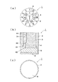
特許文献2には、他の形式の刻印装置が開示されている。図7に、特許文献2に開示される刻印装置を示す。図7(a)は、特許文献2の刻印装置の平面図であり、図7(b)は図7(a)に示す刻印装置を操作するための回転治具を示す。
図7に示す如く、特許文献2に開示される刻印装置(200)は、金型装置に固定して取付けられる固定筒(201)と、固定筒(201)に回転可能に挿入される多数の回転筒(202)と、固定筒(201)の中心軸に沿って回転可能に配される指標軸(203)から構成される。回転筒(202)の上面には、それぞれ文字が刻設されている。
このような形式の刻印装置(200)は、多数の回転筒(202)を備えるので、異なる意味を示す刻印を成形品に施すのに好適に使用可能である。
As shown in FIG. 7, the marking device (200) disclosed in
Since the marking device (200) of this type includes a large number of rotating cylinders (202), the marking device (200) can be suitably used for marking a molded product with different meanings.
しかしながら、特許文献2に示す刻印装置(200)は、回転筒(202)の回転操作にあたって、図7(b)に示すような特別の回転操作用治具(205)を準備する必要がある。回転筒(202)の回転操作のためには、二股に分かれた回転操作用治具(205)の先端を、回転筒(202)上面に施された凹部(221)に挿入し、回転操作用治具(205)を軸回りに回転させる必要がある。このとき、回転操作対象の回転筒(202)に隣接する回転筒(202)が、回転操作対象の回転筒(202)とともに回転することがあり、刻印装置(200)上面の刻印表示の調整は、非常に煩わしいものとなる。
However, the marking device (200) shown in
本発明は上記実情を鑑みてなされたものであって、2つの異なる意味を示す刻印を簡単な操作で、精度のよい刻印表示を行うことが可能な型内脱着式刻印装置を提供することを目的とする。 The present invention has been made in view of the above circumstances, and provides an in-mold detachable marking device capable of performing accurate marking display with simple operations for markings having two different meanings. Objective.
請求項1記載の発明は、成型金型内に嵌入される略円筒形状の刻印装置(1)であって、該刻印装置(1)は、前記成型金型に対して固定して配されるとともに、上面に文字が刻設された略円筒形状の固定筒(2)と、該固定筒(2)に回転可能に挿入されるとともに上面に文字が刻設された略円筒形状の回転筒(3)と、該回転筒(3)に回転可能に挿入される指標軸(4)と、該指標軸(4)が一の方向へ回転するときに該指標軸(4)のみを回転可能とし、該指標軸(4)が他の方向へ回転するときに前記回転筒(3)が前記指標軸(4)とともに回転可能とする制御機構からなり、該制御機構は、前記回転筒(3)内部に形成される制御空間(71)と、前記指標軸(4)内部に挿入されるとともに半径方向に出没可能な固定子(75)からなり、前記制御空間(71)は、前記回転筒(3)の軸と同心の円柱形状の円柱空間(72)と、該円柱空間(72)から半径方向に突出する突出空間(73)からなり、該突出空間(73)の辺を構成するとともに前記円柱空間(72)から延設する一対の辺のうち一方の前記円柱空間(72)側端部同士を結んだ辺に対する傾斜勾配が、前記円柱空間(72)から延設する一対の辺のうち他方の辺の前記円柱空間(72)側端部同士を結んだ辺に対する傾斜勾配よりも緩く形成され、前記固定子(75)の先端部(752)は、前記突出空間(73)内に突出し、前記指標軸(4)を前記一の方向に回転するとき、前記固定子(75)の先端部(752)は、前記緩い傾斜勾配をなす一方の辺に案内され、前記指標軸(4)内部に埋没し、前記指標軸(4)を前記他の方向に回転するとき、前記固定子(75)の先端部(752)は、前記他方の辺に引掛かり前記回転筒(3)を前記指標軸(4)とともに回転させることを特徴とする型内脱着式刻印装置(1)である。
請求項2記載の発明は、成型金型内に嵌入される略円筒形状の刻印装置(1)であって、該刻印装置(1)は、前記成型金型に対して固定して配されるとともに、上面に文字が刻設された略円筒形状の固定筒(2)と、該固定筒(2)に回転可能に挿入されるとともに上面に文字が刻設された略円筒形状の回転筒(3)と、該回転筒(3)に回転可能に挿入される指標軸(4)と、該指標軸(4)が一の方向へ回転するときに該指標軸(4)のみを回転可能とし、該指標軸(4)が他の方向へ回転するときに前記回転筒(3)が前記指標軸(4)とともに回転可能とする制御機構からなり、該制御機構は、前記回転筒(3)内部に形成される制御空間(71)と、前記指標軸(4)内部に挿入されるとともに半径方向に出没可能な固定子(75)からなり、前記制御空間(71)は、前記回転筒(3)の軸と同心の円柱形状の円柱空間(72)と、該円柱空間(72)から半径方向に突出する突出空間(73)からなり、該突出空間(73)の辺を構成するとともに前記円柱空間(72)から延設する一対の辺のうち一方の前記円柱空間(72)側端部同士を結んだ辺に対する角度が鋭角に形成され、前記円柱空間(72)から延設する一対の辺のうち他方の辺の前記円柱空間(72)側端部同士を結んだ辺に対する角度が直角又は鈍角に形成され、前記固定子(75)の先端部(752)は、前記突出空間(73)内に突出し、前記指標軸(4)を前記一の方向に回転するとき、前記固定子(75)の先端部(752)は、前記円柱空間(72)側端部同士を結んだ辺に対して鋭角を形成する辺に案内され、前記指標軸(4)内部に埋没し、前記指標軸(4)を前記他の方向に回転するとき、前記固定子(75)の先端部(752)は、前記円柱空間(72)側端部同士を結んだ辺に対して直角又は鈍角を形成する辺に引掛かり前記回転筒(3)を前記指標軸(4)とともに回転させることを特徴とする型内脱着式刻印装置(1)である。
請求項3記載の発明は、前記刻印装置(1)が更に、前記回転筒(3)下部に配される円板状の台座部(5)を備え、前記回転筒(3)下面には前記固定筒(2)上面に刻設された文字に対応する位置に凹部(81)を備え、前記台座部(5)が、該台座部(5)から出没可能とされるとともに前記凹部(81)に嵌入可能な凸部(83)を備えることを特徴とする請求項1又は2記載の型内脱着式刻印装置である。
請求項4記載の発明は、前記刻印装置(1)が更に、前記回転筒(3)下部に配される円板状の台座部(5)を備え、該台座部(5)は凹部(81)を備え、前記回転筒(3)下面には、前記固定筒(2)上面に刻設された文字に対応する位置に配されるとともに前記回転筒(3)下面から出没可能とされる凸部(83)を備え、該凸部(83)が前記凹部(81)に嵌入可能であることを特徴とする請求項1又は2記載の型内脱着式刻印装置である。
請求項5記載の発明は、前記刻印装置(1)が更に、固定ピンを備え、前記固定ピンが、前記固定筒(2)周壁に形成された穴部から挿入され前記台座部(5)周面に形成された穴部に侵入することを特徴とする請求項3又は4記載の型内脱着式刻印装置である。
請求項6記載の発明は、前記固定筒(2)下端開口部を閉塞する蓋材(6)を更に備えることを特徴とする請求項1又は2記載の型内脱着式刻印装置である。
請求項7記載の発明は、前記指標軸(4)上面に工具先端が挿入可能な凹部が形成されることを特徴とする請求項1又は2記載の型内脱着式刻印装置である。
The invention described in
The invention described in
Invention of
According to a fourth aspect of the present invention, the marking device (1) further includes a disk-shaped pedestal portion (5) disposed at a lower portion of the rotating cylinder (3), and the pedestal portion (5) is a recess (81 ), And is provided on the lower surface of the rotating cylinder (3) at a position corresponding to the characters engraved on the upper surface of the fixed cylinder (2) and protruded from the lower surface of the rotating cylinder (3). part comprising a (83), a mold detachable marking apparatus according to
Invention of
A sixth aspect of the present invention is the in-mold detachable marking apparatus according to the first or second aspect, further comprising a lid member (6) for closing the lower end opening of the fixed cylinder (2) .
A seventh aspect of the present invention is the in-mold detachable marking apparatus according to the first or second aspect, wherein a recess into which a tool tip can be inserted is formed on the upper surface of the index shaft (4) .
請求項1及び2記載の発明によれば、制御機構により、指標軸(4)の回転方向により、指標軸(4)のみの回転か、指標軸(4)と回転筒(3)の両方の回転かが定まるので、刻印装置(1)上面の刻設文字の位置合わせを容易に行うことができる。
請求項3及び4記載の発明によれば、所定位置に回転筒の位置決めを行うことができ、刻印装置(1)上面の刻設文字の位置合わせ精度を向上させることができる。
請求項5記載の発明によれば、固定筒(2)に対する台座部(5)の角度方向位置が常に一定となるので、刻印装置(1)組立時の位置決め位置の誤差の発生を防止できる。
請求項6記載の発明によれば、刻印装置(1)内部に塵等の汚染物質が侵入することが防止でき、刻印装置(1)内部の制御機構の故障を防止できる。
請求項7記載の発明によれば、刻設文字の位置合わせ作業を容易に行うことが可能となる。
According to the invention of
According to the third and fourth aspects of the invention, the rotary cylinder can be positioned at a predetermined position, and the alignment accuracy of the engraved characters on the upper surface of the marking device (1) can be improved.
According to the fifth aspect of the present invention, since the position of the pedestal portion (5) in the angular direction with respect to the fixed cylinder (2) is always constant, it is possible to prevent occurrence of an error in the positioning position when the stamping device (1) is assembled.
According to the sixth aspect of the present invention, marking device (1) inside can be prevented that contaminants such as dust from entering, thereby preventing the failure of the marking device (1) internal control mechanisms.
According to the seventh aspect of the present invention, it becomes possible to easily perform the alignment operation of the engraved characters.
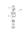
以下、本発明に係る型内脱着式刻印装置の実施形態について、図を参照しつつ説明する。図1は本発明に係る型内脱着式刻印装置を示す。図1(a)は刻印装置の平面図であり、図1(b)は刻印装置の主要構成を示す縦断面図であり、図1(c)は刻印装置の底面図である。
刻印装置(1)は、刻印装置(1)の外周輪郭を構成する略円筒状の固定筒(2)と、固定筒(2)に回転可能に挿入される略円筒状の回転筒(3)と、回転筒(3)に回転可能に挿入される指標軸(4)と、回転筒(3)の下方に配される円板状の台座部(5)と、台座部(5)の下方に配されるとともに、固定筒(2)の下端開口部を閉塞する円板状の蓋材(6)から構成される。
Hereinafter, an embodiment of an in-mold detachable marking device according to the present invention will be described with reference to the drawings. FIG. 1 shows an in-mold detachable marking apparatus according to the present invention. FIG. 1A is a plan view of the marking device, FIG. 1B is a longitudinal sectional view showing the main configuration of the marking device, and FIG. 1C is a bottom view of the marking device.
The marking device (1) includes a substantially cylindrical fixed cylinder (2) that constitutes the outer peripheral contour of the marking device (1), and a substantially cylindrical rotating cylinder (3) that is rotatably inserted into the fixed cylinder (2). An index shaft (4) that is rotatably inserted into the rotating cylinder (3), a disk-shaped pedestal part (5) disposed below the rotating cylinder (3), and a lower part of the pedestal part (5) And a disc-shaped lid member (6) for closing the lower end opening of the fixed cylinder (2).
固定筒(2)の外周面は、刻印装置(1)が金型装置のキャビティ壁面に形成された刻印装置(1)埋設用穴部内に配されたときに、該埋設用穴部の内壁面と密接し、後述するような指標軸(4)の回転操作をした際に、金型装置に対して回転しないようにされる。
固定筒(2)の内壁には、回転筒(2)、台座部(5)及び蓋材(6)の軸方向の位置を定めるための段部がそれぞれ形成され、固定筒(2)は、下方に向けて段々に広がる内空間を備える。回転筒(2)下端に形成される半径方向に突出する環状の突出部(21)が、固定筒(2)内壁の段部に当接し、また、台座部(5)及び蓋材(6)が、それぞれ固定筒(2)の内壁に形成された段部に当接することで、固定筒(2)と回転筒(3)の上面が面一となる。
図1に示す例においては、固定筒(2)の上面には成形品の製造月を示すために、「1」から「12」までの数字が刻設されているが、これに限定されるものではなく、所望の文字を刻設可能である。
The outer peripheral surface of the fixed cylinder (2) is the inner wall surface of the embedding hole when the imprinting device (1) is arranged in the embedding device (1) embedding hole formed on the cavity wall surface of the mold device. When the index shaft (4) is rotated as described later, it is prevented from rotating with respect to the mold apparatus.
On the inner wall of the fixed cylinder (2), stepped portions for determining the axial positions of the rotary cylinder (2), the pedestal part (5) and the lid member (6) are formed, respectively. It has an internal space that gradually expands downward. An annular projecting portion (21) projecting in the radial direction formed at the lower end of the rotating cylinder (2) abuts on the stepped portion of the inner wall of the fixed cylinder (2), and the pedestal (5) and lid (6). However, the upper surfaces of the fixed cylinder (2) and the rotating cylinder (3) are flush with each other by contacting the stepped portion formed on the inner wall of the fixed cylinder (2).
In the example shown in FIG. 1, numbers from “1” to “12” are engraved on the upper surface of the fixed cylinder (2) to indicate the month of manufacture of the molded product, but this is not limitative. A desired character can be engraved instead of a thing.
回転筒(3)の内壁には、指標軸(2)の軸方向位置を定めるための段部が形成され、回転筒(3)内部は、上部空間(31)と該上部空間(31)より広く形成される下部空間(32)で構成され、この下部空間(32)に、後述する制御機構の一部を担う制御空間が形成される。
指標軸(4)は、指標軸(4)上部を構成する円柱状の上部柱(41)と、指標軸(4)下部を構成するとともに上部柱(41)より径大に形成される下部柱(42)から構成され、下部柱(42)上面が回転筒(3)内壁に形成される段部に当接する。
指標軸(4)の長さは、回転軸(3)の長さと等しく形成され、上述の如く、台座部(5)及び蓋材(6)が、それぞれ固定筒(2)の内壁に形成された段部に当接することで、回転筒(3)と指標軸(4)の上面とが面一とされる。
回転筒(3)上面には、製造年を表す「05」から「10」までの数字と、固定筒(2)上面の特定の数字を指し示す「三角」マークが刻設されている。
A step portion for determining the axial position of the index shaft (2) is formed on the inner wall of the rotating cylinder (3), and the inside of the rotating cylinder (3) is formed by the upper space (31) and the upper space (31). A lower space (32) formed widely is formed, and a control space serving as a part of a control mechanism described later is formed in the lower space (32).
The index axis (4) includes a columnar upper column (41) that forms the upper part of the index axis (4), and a lower column that forms the lower part of the index axis (4) and is larger in diameter than the upper column (41). (42), and the upper surface of the lower column (42) abuts on a step formed on the inner wall of the rotating cylinder (3).
The length of the index shaft (4) is formed equal to the length of the rotation shaft (3), and as described above, the pedestal portion (5) and the lid member (6) are formed on the inner wall of the fixed cylinder (2), respectively. The rotating cylinder (3) and the upper surface of the indicator shaft (4) are flush with each other by contacting the stepped portion.
On the upper surface of the rotating cylinder (3), numbers from “05” to “10” representing the year of manufacture and “triangle” marks indicating specific numbers on the upper surface of the fixed cylinder (2) are engraved.
指標軸(4)の上面には、「矢印」マークが刻設され、この「矢印」マークはマイナスドライバ先端が挿入可能な溝形状となっている。
回転筒(3)は、固定筒(2)に対して回転可能とされ、指標軸(4)は、回転筒(3)に対して、回転可能とされる。例えば、回転筒(3)の「三角」マークが固定筒(2)の「1」の数字を指し示す位置にあり、指標軸(4)の「矢印」マークが回転筒(3)の「05」の数字を指し示す位置にあるとき、成形品に「2005年1月」を示す製造年月の刻印を施すことができる。
An “arrow” mark is engraved on the upper surface of the index shaft (4), and this “arrow” mark has a groove shape into which the tip of a minus driver can be inserted.
The rotating cylinder (3) is rotatable with respect to the fixed cylinder (2), and the index shaft (4) is rotatable with respect to the rotating cylinder (3). For example, the “triangle” mark on the rotating cylinder (3) is at a position indicating the number “1” on the fixed cylinder (2), and the “arrow” mark on the index axis (4) is “05” on the rotating cylinder (3). When it is in a position indicating the number, the date of manufacture indicating “January 2005” can be applied to the molded product.
台座部(5)は、回転筒(3)或いは指標軸(4)の回転動作にかかわらず、回転しない。また蓋材(6)は、固定筒(2)下端開口部を閉塞し、刻印装置(1)内部に埃塵が侵入することを防止する。 The pedestal portion (5) does not rotate regardless of the rotating operation of the rotating cylinder (3) or the index shaft (4). The lid member (6) closes the lower end opening of the fixed cylinder (2) and prevents dust from entering the stamping device (1).
図2は、回転筒(3)の底面図であり、回転筒(3)の下部構造を詳細に示す。
回転筒(3)の下部空間(32)には、環状の回転制御リング(33)が固定される。回転制御リング(33)は所定の厚さを有し、この厚さ分の下部空間(32)の領域に制御空間(71)が形成される。
制御空間(71)は、回転制御リング(33)内壁の内接円(即ち、図2中、点線で示される円)で定義される円柱空間(72)と、円柱空間(72)から半径方向に突出する突出空間(73)から構成される。
突出空間(73)は、図2において、回転筒(3)上面に刻設される数字或いはマークの総数と同数の数だけ形成され、これらの数字或いはマークの配置に対応して形成される。
即ち、図1に示す例においては、回転筒(3)上面には、「05」から「10」の数字と「三角」マークが刻設されており、7つの数字・マークが配されている。これら、数字・マークは周方向に等間隔に配されている。突出空間(73)は、回転筒(3)の数字・マークと同数且つ同配置とされ、7つの突出空間(73)が周方向に等間隔に形成されている。
FIG. 2 is a bottom view of the rotating cylinder (3) and shows the lower structure of the rotating cylinder (3) in detail.
An annular rotation control ring (33) is fixed in the lower space (32) of the rotating cylinder (3). The rotation control ring (33) has a predetermined thickness, and a control space (71) is formed in the region of the lower space (32) corresponding to this thickness.
The control space (71) includes a cylindrical space (72) defined by an inscribed circle (that is, a circle indicated by a dotted line in FIG. 2) of the inner wall of the rotation control ring (33), and a radial direction from the cylindrical space (72). It is comprised from the protrusion space (73) which protrudes.
In FIG. 2, the protruding space (73) is formed by the same number as the total number of the numbers or marks engraved on the upper surface of the rotary cylinder (3), and is formed corresponding to the arrangement of these numbers or marks.
That is, in the example shown in FIG. 1, numbers “05” to “10” and a “triangle” mark are engraved on the upper surface of the rotating cylinder (3), and seven numbers / marks are arranged. . These numbers and marks are arranged at equal intervals in the circumferential direction. The protruding spaces (73) have the same number and the same arrangement as the numbers and marks of the rotating cylinder (3), and seven protruding spaces (73) are formed at equal intervals in the circumferential direction.
図2に示す突出空間(73)は、台形断面を備えるが、本発明においては、これに限られるものではなく、以下のような条件を満たすものであればよい。
円柱空間(72)から延設する一対の辺(L1,L2)を、ここで参照する。この一対の辺の端部のうち円柱空間側端部をそれぞれE1,E2とする。ここで点E1と点E2とを結んだ線に対する辺L1の角度と、点E1と点E2とを結んだ線に対する辺L1の角度が異なるものであれば、突出空間(73)の形状は任意の形状を採用可能である。
尚、好ましくは、一方の角度を鋭角とし、他方の角度を直角以上の鈍角とすることが好ましい。
The projecting space (73) shown in FIG. 2 has a trapezoidal cross section, but is not limited to this in the present invention, and may be any as long as the following conditions are satisfied.
A pair of sides (L1, L2) extending from the cylindrical space (72) will be referred to here. Of the end portions of the pair of sides, the end portions on the cylindrical space side are denoted by E1 and E2, respectively. If the angle of the side L1 with respect to the line connecting the points E1 and E2 is different from the angle of the side L1 with respect to the line connecting the points E1 and E2, the shape of the protruding space (73) is arbitrary. The shape can be adopted.
Preferably, one angle is an acute angle and the other angle is an obtuse angle of a right angle or more.
回転筒(3)はその下端面に更に、凹部(81)を備える。凹部(81)は、固定筒(2)上面に刻設される文字・数字・マークに対応する位置に配される。即ち、図1に示す例において、固定筒(2)上面には「1」から「12」までの数字が周方向に等間隔に刻設されている。したがって、回転筒(3)下面において、12個の凹部(81)が周方向に等間隔に形成されている。 The rotating cylinder (3) is further provided with a recess (81) at its lower end surface. The concave portion (81) is arranged at a position corresponding to a letter, number, or mark carved on the upper surface of the fixed cylinder (2). That is, in the example shown in FIG. 1, numbers from “1” to “12” are engraved on the upper surface of the fixed cylinder (2) at equal intervals in the circumferential direction. Therefore, twelve recesses (81) are formed at equal intervals in the circumferential direction on the lower surface of the rotating cylinder (3).
図3は、指標軸(4)の断面図であり、指標軸(4)内部の詳細を示す。
指標軸(4)の下部柱(42)には、下部柱(42)直径に沿って穴部(74)が形成され、この穴部(74)内に固定子(75)が埋設される。
固定子(75)は、コイルバネ(751)と、コイルバネ(751)先端に取付けられる先端部(751)から構成され、先端部(751)は下部柱(42)周面から一部が突出し、且つコイルバネ(751)の圧縮により、この突出した一部が完全に穴部(74)内に収容可能とされる。先端部(751)の先端部分は半球形状に形成されている。
FIG. 3 is a cross-sectional view of the index axis (4), showing details inside the index axis (4).
A hole (74) is formed in the lower column (42) of the index shaft (4) along the diameter of the lower column (42), and a stator (75) is embedded in the hole (74).
The stator (75) includes a coil spring (751) and a tip (751) attached to the tip of the coil spring (751), and the tip (751) partially protrudes from the peripheral surface of the lower column (42), and By the compression of the coil spring (751), the protruding part can be completely accommodated in the hole (74). The tip of the tip (751) has a hemispherical shape.
図4は、刻印装置(1)の底面図であり、蓋材(6)並びに台座部(5)を取り除いた状態を示す。
制御機構は、上記の固定子(75)と制御空間(71)により構成される。
指標軸(4)の下部柱(42)は、図3において点線で囲まれた円柱空間(72)内に挿入され、下部柱(42)の周面輪郭は、図3の点線と一致している。そして、下部柱(42)に埋設される固定子(75)の先端部(752)は、突出空間(73)内に突出する。
この状態において、緩い傾斜勾配である突出空間(73)の辺L1側に向かって、指標軸(4)を回転させる(即ち、反時計回りに指標軸(4)を回転させる)。このとき、固定子(75)の先端部(752)は、辺L1に沿って案内され、コイルバネ(751)を圧縮変位させながら、下部柱(42)に形成された穴部(74)内に埋没する。そして、隣接する突出空間(73)に至ったとき、再度、下部柱(42)から突出し、指標軸(4)の回転動作の位置決めを行う。
FIG. 4 is a bottom view of the marking device (1), and shows a state in which the lid member (6) and the pedestal portion (5) are removed.
The control mechanism is configured by the stator (75) and the control space (71).
The lower column (42) of the index axis (4) is inserted into the cylindrical space (72) surrounded by the dotted line in FIG. 3, and the peripheral surface contour of the lower column (42) coincides with the dotted line in FIG. Yes. And the front-end | tip part (752) of the stator (75) embed | buried under a lower pillar (42) protrudes in the protrusion space (73).
In this state, the index axis (4) is rotated toward the side L1 side of the protruding space (73) having a gentle slope (that is, the index axis (4) is rotated counterclockwise). At this time, the distal end portion (752) of the stator (75) is guided along the side L1, and the coil spring (751) is compressed and displaced into the hole (74) formed in the lower column (42). Buried. When the adjacent projecting space (73) is reached, it projects again from the lower column (42), and positioning of the rotation operation of the index shaft (4) is performed.
一方で、きつい傾斜勾配である突出空間(73)の辺L2側に向かって、指標軸(4)を回転させる(即ち、時計回りに指標軸(4)を回転させる)。このとき、固定子(75)の先端部(752)は、辺L2に引掛かり、回転筒(3)を指標軸(4)とともに回転させる。
このようにして、制御機構は、回転方向によって、指標軸(4)のみを回転可能とするか、指標軸(4)と回転筒(3)をともに回転可能とするかを選択可能にする。
On the other hand, the index axis (4) is rotated toward the side L2 side of the projecting space (73) having a tight slope (that is, the index axis (4) is rotated clockwise). At this time, the tip (752) of the stator (75) is hooked on the side L2, and the rotating cylinder (3) is rotated together with the index shaft (4).
In this way, the control mechanism enables selection of whether only the index shaft (4) can be rotated or both the index shaft (4) and the rotating cylinder (3) can be rotated, depending on the rotation direction.
図5は、台座部(5)の断面詳細図である。
台座部(5)は、上面に穴部(82)が形成され、穴部(82)に凸部(83)が埋設される。凸部(83)は、コイルバネ(831)と、コイルバネ(831)先端に取付けられる球状の先端部(832)からなる。先端部(832)の一部は、台座部(5)上面から突出可能であるとともに、コイルバネ(831)の圧縮により穴部(82)内部に埋没可能となる。
FIG. 5 is a detailed cross-sectional view of the pedestal portion (5).
The pedestal portion (5) has a hole (82) formed on the upper surface, and a convex portion (83) is embedded in the hole (82). The convex portion (83) includes a coil spring (831) and a spherical tip portion (832) attached to the tip of the coil spring (831). A part of the tip portion (832) can protrude from the upper surface of the pedestal portion (5) and can be buried in the hole portion (82) by compression of the coil spring (831).
凸部(83)の先端は、図2及び図4に示す回転筒(3)下面に形成される凹部(81)に嵌入される。これにより、回転筒(3)の回転位置の位置決めが行われる。
尚、固定筒(2)周面を貫く穴部を形成し、更に、台座部(5)の周面に台座部(5)直径に沿って穴部を形成し、これら穴部を連通させるとともにピンを挿入することが好ましい。
このように構成することで、台座部(5)の凸部(83)と固定筒(2)上面の文字・数字・マークの位置関係が常に一定となり、組立による位置決めの誤差が取り除かれる。
The tip of the convex portion (83) is fitted into a concave portion (81) formed on the lower surface of the rotating cylinder (3) shown in FIGS. Thereby, positioning of the rotation position of the rotating cylinder (3) is performed.
In addition, the hole which penetrates a fixed cylinder (2) peripheral surface is formed, Furthermore, a hole is formed in the peripheral surface of a base part (5) along a base part (5) diameter, and these hole parts are connected. It is preferable to insert a pin.
With this configuration, the positional relationship between the letters (numbers) and the marks on the top surface of the pedestal (5) and the fixed cylinder (2) is always constant, and positioning errors due to assembly are eliminated.
更には、回転筒(3)の凹部(81)の代わりに、図5に示す凸部(83)の構造を配し、台座部(5)の凸部(83)の代わりに、図2及び図4に示す回転筒(3)の凹部(81)の構造を採っても、同様の効果を得ることが可能である。 Furthermore, instead of the concave portion (81) of the rotating cylinder (3), the structure of the convex portion (83) shown in FIG. 5 is arranged, and instead of the convex portion (83) of the base portion (5), FIG. Even if the structure of the concave portion (81) of the rotating cylinder (3) shown in FIG. 4 is adopted, the same effect can be obtained.
本発明は、異なる意味を有する刻印を施すための型内脱着式刻印装置に好適に適用される。 The present invention is preferably applied to an in-mold detachable marking device for marking with different meanings.
1・・・・・型内脱着式刻印装置
2・・・・・固定筒
3・・・・・回転筒
4・・・・・指標軸
5・・・・・台座部
6・・・・・蓋材
71・・・・制御空間
72・・・・円柱空間
73・・・・突出空間
81・・・・凹部
83・・・・凸部
DESCRIPTION OF
Claims (7)
該刻印装置(1)は、前記成型金型に対して固定して配されるとともに、上面に文字が刻設された略円筒形状の固定筒(2)と、
該固定筒(2)に回転可能に挿入されるとともに上面に文字が刻設された略円筒形状の回転筒(3)と、
該回転筒(3)に回転可能に挿入される指標軸(4)と、
該指標軸(4)が一の方向へ回転するときに該指標軸(4)のみを回転可能とし、該指標軸(4)が他の方向へ回転するときに前記回転筒(3)が前記指標軸(4)とともに回転可能とする制御機構からなり、
該制御機構は、
前記回転筒(3)内部に形成される制御空間(71)と、
前記指標軸(4)内部に挿入されるとともに半径方向に出没可能な固定子(75)からなり、
前記制御空間(71)は、前記回転筒(3)の軸と同心の円柱形状の円柱空間(72)と、
該円柱空間(72)から半径方向に突出する突出空間(73)からなり、
該突出空間(73)の辺を構成するとともに前記円柱空間(72)から延設する一対の辺のうち一方の前記円柱空間(72)側端部同士を結んだ辺に対する傾斜勾配が、前記円柱空間(72)から延設する一対の辺のうち他方の辺の前記円柱空間(72)側端部同士を結んだ辺に対する傾斜勾配よりも緩く形成され、
前記固定子(75)の先端部(752)は、前記突出空間(73)内に突出し、
前記指標軸(4)を前記一の方向に回転するとき、前記固定子(75)の先端部(752)は、前記緩い傾斜勾配をなす一方の辺に案内され、前記指標軸(4)内部に埋没し、
前記指標軸(4)を前記他の方向に回転するとき、前記固定子(75)の先端部(752)は、前記他方の辺に引掛かり前記回転筒(3)を前記指標軸(4)とともに回転させることを特徴とする型内脱着式刻印装置(1)。 A marking apparatus of substantially cylindrical shape which is fitted into the mold (1),
The marking device (1) is fixedly arranged with respect to the molding die, and has a substantially cylindrical fixed tube (2) with characters engraved on the upper surface thereof,
A substantially cylindrical rotating cylinder (3) that is rotatably inserted into the fixed cylinder (2) and has characters engraved on its upper surface;
An index shaft (4) rotatably inserted into the rotating cylinder (3) ;
When the index shaft (4) rotates in one direction, only the index shaft (4) can be rotated, and when the index shaft (4) rotates in the other direction, the rotary cylinder (3) It consists of a control mechanism that can rotate with the index shaft (4) ,
The control mechanism is
A control space (71) formed inside the rotating cylinder (3) ;
A stator (75) inserted into the index shaft (4) and capable of protruding and retracting in the radial direction;
The control space (71) includes a cylindrical cylindrical space (72) concentric with the axis of the rotating cylinder (3) ,
A projecting space (73) projecting radially from the cylindrical space (72) ;
The inclination gradient for one of the columnar space (72) side end portion connecting it sides to each other of the pair of sides extending from said cylinder space (72) while constituting the protruding edges of the space (73), said cylinder Of the pair of sides extending from the space (72), the other side is formed more gently than the slope with respect to the side connecting the cylindrical space (72) side ends,
The tip (752) of the stator (75) protrudes into the protruding space (73),
When the index shaft (4) is rotated in the one direction, the tip end portion (752) of the stator (75) is guided to one side forming the gentle slope, and the index shaft (4) Buried in the
When the index shaft (4) is rotated in the other direction, the tip (752) of the stator (75) is hooked on the other side, and the rotating cylinder (3) is moved to the index shaft (4). An in-mold detachable marking device (1) characterized by being rotated together .
該刻印装置(1)は、前記成型金型に対して固定して配されるとともに、上面に文字が刻設された略円筒形状の固定筒(2)と、 The marking device (1) is fixedly arranged with respect to the molding die, and has a substantially cylindrical fixed tube (2) with characters engraved on the upper surface,
該固定筒(2)に回転可能に挿入されるとともに上面に文字が刻設された略円筒形状の回転筒(3)と、 A substantially cylindrical rotary cylinder (3) which is rotatably inserted into the fixed cylinder (2) and has characters engraved on its upper surface;
該回転筒(3)に回転可能に挿入される指標軸(4)と、 An index shaft (4) rotatably inserted into the rotating cylinder (3);
該指標軸(4)が一の方向へ回転するときに該指標軸(4)のみを回転可能とし、該指標軸(4)が他の方向へ回転するときに前記回転筒(3)が前記指標軸(4)とともに回転可能とする制御機構からなり、 When the index shaft (4) rotates in one direction, only the index shaft (4) can be rotated, and when the index shaft (4) rotates in the other direction, the rotating cylinder (3) It consists of a control mechanism that can rotate with the index shaft (4),
該制御機構は、 The control mechanism is
前記回転筒(3)内部に形成される制御空間(71)と、 A control space (71) formed inside the rotating cylinder (3);
前記指標軸(4)内部に挿入されるとともに半径方向に出没可能な固定子(75)からなり、 A stator (75) inserted into the index shaft (4) and capable of protruding and retracting in the radial direction;
前記制御空間(71)は、前記回転筒(3)の軸と同心の円柱形状の円柱空間(72)と、 The control space (71) includes a cylindrical cylindrical space (72) concentric with the axis of the rotating cylinder (3),
該円柱空間(72)から半径方向に突出する突出空間(73)からなり、 A projecting space (73) projecting radially from the cylindrical space (72);
該突出空間(73)の辺を構成するとともに前記円柱空間(72)から延設する一対の辺のうち一方の前記円柱空間(72)側端部同士を結んだ辺に対する角度が鋭角に形成され、 The angle with respect to the side which connected the edge part of one said cylindrical space (72) side is formed in an acute angle among the pair of sides which comprise the side of this protrusion space (73), and are extended from the said cylindrical space (72). ,
前記円柱空間(72)から延設する一対の辺のうち他方の辺の前記円柱空間(72)側端部同士を結んだ辺に対する角度が直角又は鈍角に形成され、 The angle of the other side of the pair of sides extending from the cylindrical space (72) with respect to the side connecting the ends of the cylindrical space (72) is formed at a right angle or an obtuse angle.
前記固定子(75)の先端部(752)は、前記突出空間(73)内に突出し、 The tip (752) of the stator (75) protrudes into the protruding space (73),
前記指標軸(4)を前記一の方向に回転するとき、前記固定子(75)の先端部(752)は、前記円柱空間(72)側端部同士を結んだ辺に対して鋭角を形成する辺に案内され、前記指標軸(4)内部に埋没し、 When the index shaft (4) is rotated in the one direction, the tip (752) of the stator (75) forms an acute angle with respect to the side connecting the cylindrical space (72) side ends. And is buried inside the indicator axis (4),
前記指標軸(4)を前記他の方向に回転するとき、前記固定子(75)の先端部(752)は、前記円柱空間(72)側端部同士を結んだ辺に対して直角又は鈍角を形成する辺に引掛かり前記回転筒(3)を前記指標軸(4)とともに回転させることを特徴とする型内脱着式刻印装置(1)。 When the index shaft (4) is rotated in the other direction, the tip (752) of the stator (75) is perpendicular or obtuse to the side connecting the cylindrical space (72) side ends. An in-mold detachable stamping device (1) characterized in that the rotating cylinder (3) is rotated together with the index shaft (4) by being hooked on a side forming a circle.
前記回転筒(3)下面には前記固定筒(2)上面に刻設された文字に対応する位置に凹部(81)を備え、 The lower surface of the rotating cylinder (3) is provided with a recess (81) at a position corresponding to the characters carved on the upper surface of the fixed cylinder (2).
前記台座部(5)が、該台座部(5)から出没可能とされるとともに前記凹部(81)に嵌入可能な凸部(83)を備えることを特徴とする請求項1又は2記載の型内脱着式刻印装置(1)。 3. The mold according to claim 1, wherein the pedestal part (5) is provided with a convex part (83) that can be projected and retracted from the pedestal part (5) and can be fitted into the concave part (81). Inner detachable marking device (1).
該台座部(5)は凹部(81)を備え、 The pedestal (5) includes a recess (81),
前記回転筒(3)下面には、前記固定筒(2)上面に刻設された文字に対応する位置に配されるとともに前記回転筒(3)下面から出没可能とされる凸部(83)を備え、 On the lower surface of the rotating cylinder (3), a convex portion (83) is arranged at a position corresponding to the characters engraved on the upper surface of the fixed cylinder (2) and can protrude from the lower surface of the rotating cylinder (3). With
該凸部(83)が前記凹部(81)に嵌入可能であることを特徴とする請求項1又は2記載の型内脱着式刻印装置(1)。 The in-mold detachable marking device (1) according to claim 1 or 2, wherein the convex portion (83) can be fitted into the concave portion (81).
前記固定ピンが、前記固定筒(2)周壁に形成された穴部から挿入され前記台座部(5)周面に形成された穴部に侵入することを特徴とする請求項3又は4記載の型内脱着式刻印装置(1)。 The said fixing pin is inserted from the hole part formed in the said fixed cylinder (2) peripheral wall, and penetrate | invades into the hole part formed in the said base part (5) peripheral surface. In-mold removable marking device (1).
Priority Applications (8)
| Application Number | Priority Date | Filing Date | Title |
|---|---|---|---|
| JP2005164861A JP3958770B2 (en) | 2005-06-03 | 2005-06-03 | In-mold removable marking device |
| US11/211,366 US7171894B2 (en) | 2005-06-03 | 2005-08-24 | Removable marking device for a mold |
| DE102005042143A DE102005042143B4 (en) | 2005-06-03 | 2005-09-05 | Removable marking device for a mold |
| GB0517940A GB2426734B (en) | 2005-06-03 | 2005-09-05 | A removable marking device for a mold |
| IT000045A ITVE20050045A1 (en) | 2005-06-03 | 2005-09-23 | REMOVABLE MARKING DEVICE FOR A MOLD. |
| CN2005101058960A CN1872519B (en) | 2005-06-03 | 2005-09-29 | A removable marking device for a mold |
| FR0509990A FR2886570B1 (en) | 2005-06-03 | 2005-09-30 | REMOVABLE MARKING DEVICE FOR A MOLD |
| ES200502500A ES2307358A1 (en) | 2005-06-03 | 2005-10-13 | Removable marking device for a mold |
Applications Claiming Priority (1)
| Application Number | Priority Date | Filing Date | Title |
|---|---|---|---|
| JP2005164861A JP3958770B2 (en) | 2005-06-03 | 2005-06-03 | In-mold removable marking device |
Publications (3)
| Publication Number | Publication Date |
|---|---|
| JP2006335010A JP2006335010A (en) | 2006-12-14 |
| JP2006335010A5 JP2006335010A5 (en) | 2007-03-08 |
| JP3958770B2 true JP3958770B2 (en) | 2007-08-15 |
Family
ID=35220793
Family Applications (1)
| Application Number | Title | Priority Date | Filing Date |
|---|---|---|---|
| JP2005164861A Active JP3958770B2 (en) | 2005-06-03 | 2005-06-03 | In-mold removable marking device |
Country Status (8)
| Country | Link |
|---|---|
| US (1) | US7171894B2 (en) |
| JP (1) | JP3958770B2 (en) |
| CN (1) | CN1872519B (en) |
| DE (1) | DE102005042143B4 (en) |
| ES (1) | ES2307358A1 (en) |
| FR (1) | FR2886570B1 (en) |
| GB (1) | GB2426734B (en) |
| IT (1) | ITVE20050045A1 (en) |
Families Citing this family (17)
| Publication number | Priority date | Publication date | Assignee | Title |
|---|---|---|---|---|
| US8011638B2 (en) * | 2005-08-24 | 2011-09-06 | Uratanishoji Kabushiki Kaisha | Marking device |
| JP4739425B2 (en) * | 2009-01-09 | 2011-08-03 | 浦谷商事株式会社 | Stamping device |
| JP4279861B2 (en) * | 2006-09-13 | 2009-06-17 | 浦谷商事株式会社 | Stamping device |
| US7637473B2 (en) * | 2007-03-22 | 2009-12-29 | Universal Trim Supply Co., Ltd. | Date code marking system |
| CN101224612A (en) * | 2008-01-25 | 2008-07-23 | 台达电子零组件(东莞)有限公司 | Manufacturing fan blade module assembly and manufacturing method thereof |
| JP5342817B2 (en) * | 2008-06-26 | 2013-11-13 | 矢崎総業株式会社 | Mold device and module for electrical connection |
| SG193210A1 (en) * | 2010-03-01 | 2013-09-30 | Asm Tech Singapore Pte Ltd | Apparatus for molding electronic components |
| ITVE20100038A1 (en) * | 2010-07-06 | 2012-01-07 | Uratanishoji Kabushiki Kaisha | MARKING DEVICE |
| US9127620B2 (en) * | 2011-07-29 | 2015-09-08 | Honda Motor Co., Ltd. | Methods and systems for marking a cylinder head |
| CN102529465B (en) * | 2011-10-21 | 2014-04-09 | 昆山上达精密配件有限公司 | Die date stamp |
| JP5700457B2 (en) * | 2012-12-10 | 2015-04-15 | ジヤトコ株式会社 | Lot mark assignment structure |
| CN104044244B (en) * | 2013-03-12 | 2018-05-18 | 汉达精密电子(昆山)有限公司 | date stamp |
| CN104816555A (en) * | 2015-04-20 | 2015-08-05 | 中山市利群精密实业有限公司 | Device for mold identifying date |
| JP2018116036A (en) * | 2017-01-13 | 2018-07-26 | 株式会社エンプラス | Unit for mounting marker |
| EP3470809B1 (en) * | 2017-10-16 | 2020-07-15 | Kistler Holding AG | Pressure sensor for a metal or plastics processing tool |
| CN108297597B (en) * | 2017-12-11 | 2023-08-04 | 天津智源机械制造股份有限公司 | Stamping steel seal tool |
| ES2823548B2 (en) * | 2019-11-06 | 2021-12-16 | Comercial De Utiles Y Moldes Sa | Dating system for molds |
Family Cites Families (14)
| Publication number | Priority date | Publication date | Assignee | Title |
|---|---|---|---|---|
| DE3509274C1 (en) * | 1985-03-15 | 1986-09-18 | HASCO-Normalien Hasenclever & Co, 5880 Lüdenscheid | Injection molding or pressing tool for processing plastic masses |
| JPS63101519U (en) * | 1986-12-24 | 1988-07-01 | ||
| WO1989002831A1 (en) * | 1987-10-01 | 1989-04-06 | Friedrich Medloby | Indicator device |
| FR2716825B1 (en) * | 1994-03-01 | 1996-04-05 | Bernard Picco | Indexable marking device for mold. |
| JP2963397B2 (en) * | 1996-07-18 | 1999-10-18 | 浦谷商事株式会社 | In-mold removable marking device |
| JPH10264161A (en) * | 1997-03-27 | 1998-10-06 | Tokyo Yamato Kikai Kigu Kk | Mold marker |
| DE19928044C2 (en) * | 1998-05-20 | 2003-06-26 | Heinrich Muenz | dies |
| DE29823524U1 (en) * | 1998-05-20 | 1999-10-28 | Muenz Heinrich | Embossing stamp |
| US6308929B1 (en) * | 1998-10-22 | 2001-10-30 | Klaus A. Wieder | Mold insert |
| JP3470880B2 (en) * | 1999-02-12 | 2003-11-25 | 浦谷商事株式会社 | In-mold removable marking device |
| ES1047299Y (en) * | 2000-10-05 | 2001-08-16 | Pruna Alberto Navarra | MARKER FOR CONFORMATION MOLDS OF PLASTIC PARTS. |
| ES2246382T3 (en) * | 2002-10-14 | 2006-02-16 | Comercial De Utiles Y Moldes, S.A. | SEQUENTIAL NUMBERER FOR INJECTION MOLDS. |
| EP1452294B1 (en) * | 2003-02-27 | 2005-07-20 | Comercial de Utiles y Moldes, S.A. | Universal marking insert for injection moulds |
| JP4002556B2 (en) * | 2004-03-12 | 2007-11-07 | 浦谷商事株式会社 | In-mold removable marking device |
-
2005
- 2005-06-03 JP JP2005164861A patent/JP3958770B2/en active Active
- 2005-08-24 US US11/211,366 patent/US7171894B2/en active Active
- 2005-09-05 DE DE102005042143A patent/DE102005042143B4/en active Active
- 2005-09-05 GB GB0517940A patent/GB2426734B/en active Active
- 2005-09-23 IT IT000045A patent/ITVE20050045A1/en unknown
- 2005-09-29 CN CN2005101058960A patent/CN1872519B/en active Active
- 2005-09-30 FR FR0509990A patent/FR2886570B1/en active Active
- 2005-10-13 ES ES200502500A patent/ES2307358A1/en active Pending
Also Published As
| Publication number | Publication date |
|---|---|
| ITVE20050045A1 (en) | 2006-12-04 |
| FR2886570A1 (en) | 2006-12-08 |
| DE102005042143A1 (en) | 2006-12-07 |
| US20060272519A1 (en) | 2006-12-07 |
| GB2426734A (en) | 2006-12-06 |
| CN1872519B (en) | 2011-08-03 |
| DE102005042143B4 (en) | 2007-04-19 |
| FR2886570B1 (en) | 2012-08-31 |
| ES2307358A1 (en) | 2008-11-16 |
| US7171894B2 (en) | 2007-02-06 |
| CN1872519A (en) | 2006-12-06 |
| GB0517940D0 (en) | 2005-10-12 |
| JP2006335010A (en) | 2006-12-14 |
| GB2426734B (en) | 2010-09-29 |
Similar Documents
| Publication | Publication Date | Title |
|---|---|---|
| JP3958770B2 (en) | In-mold removable marking device | |
| JP4279861B2 (en) | Stamping device | |
| JP2963397B2 (en) | In-mold removable marking device | |
| US6354560B1 (en) | Marking device for molding tool | |
| US7676935B2 (en) | Angle-measurement system and method for production of an angle-measurement system | |
| JP2006201145A (en) | Tool for measuring screw hole | |
| US7502280B2 (en) | Position indicator, measuring apparatus and method of manufacturing a position indicator | |
| JP4002556B2 (en) | In-mold removable marking device | |
| JP4891426B2 (en) | Pressure gauge | |
| CN107931521A (en) | Wax-pattern positioner and wax-pattern assembling method for flanged disk casting | |
| EP1467174A2 (en) | Displaying device for dial gauge | |
| CN104884219A (en) | In-mold detachable stamping device | |
| US7252136B2 (en) | Numbering device for molded or cast parts | |
| US7637473B2 (en) | Date code marking system | |
| JP2000229325A (en) | In-mold detachable stamping apparatus | |
| JP2017058231A (en) | Lock mechanism of operation member | |
| US6018114A (en) | Rotary valve of brass instrument | |
| JP4739425B2 (en) | Stamping device | |
| JP5550529B2 (en) | Method for measuring the inner shape of tire molds | |
| JP4392720B2 (en) | Pneumatic tire wheel and method for measuring eccentric fitting amount of pneumatic tire using this wheel | |
| JP2019162645A (en) | Imprinting device, and component for imprinting | |
| JP2019074528A (en) | Pressure sensor for metal or plastic processing tool | |
| US20210129401A1 (en) | Dating system for molds | |
| KR100319403B1 (en) | Date marked pin for molding | |
| JP3010196B2 (en) | Chamfering machine |
Legal Events
| Date | Code | Title | Description |
|---|---|---|---|
| A521 | Request for written amendment filed |
Free format text: JAPANESE INTERMEDIATE CODE: A523 Effective date: 20070119 |
|
| A621 | Written request for application examination |
Free format text: JAPANESE INTERMEDIATE CODE: A621 Effective date: 20070129 |
|
| A871 | Explanation of circumstances concerning accelerated examination |
Free format text: JAPANESE INTERMEDIATE CODE: A871 Effective date: 20070130 |
|
| A975 | Report on accelerated examination |
Free format text: JAPANESE INTERMEDIATE CODE: A971005 Effective date: 20070301 |
|
| A131 | Notification of reasons for refusal |
Free format text: JAPANESE INTERMEDIATE CODE: A131 Effective date: 20070312 |
|
| A521 | Request for written amendment filed |
Free format text: JAPANESE INTERMEDIATE CODE: A523 Effective date: 20070320 |
|
| TRDD | Decision of grant or rejection written | ||
| A01 | Written decision to grant a patent or to grant a registration (utility model) |
Free format text: JAPANESE INTERMEDIATE CODE: A01 Effective date: 20070418 |
|
| A61 | First payment of annual fees (during grant procedure) |
Free format text: JAPANESE INTERMEDIATE CODE: A61 Effective date: 20070510 |
|
| R150 | Certificate of patent or registration of utility model |
Ref document number: 3958770 Country of ref document: JP Free format text: JAPANESE INTERMEDIATE CODE: R150 Free format text: JAPANESE INTERMEDIATE CODE: R150 |
|
| FPAY | Renewal fee payment (event date is renewal date of database) |
Free format text: PAYMENT UNTIL: 20110518 Year of fee payment: 4 |
|
| R250 | Receipt of annual fees |
Free format text: JAPANESE INTERMEDIATE CODE: R250 |
|
| FPAY | Renewal fee payment (event date is renewal date of database) |
Free format text: PAYMENT UNTIL: 20120518 Year of fee payment: 5 |
|
| R250 | Receipt of annual fees |
Free format text: JAPANESE INTERMEDIATE CODE: R250 |
|
| FPAY | Renewal fee payment (event date is renewal date of database) |
Free format text: PAYMENT UNTIL: 20120518 Year of fee payment: 5 |
|
| FPAY | Renewal fee payment (event date is renewal date of database) |
Free format text: PAYMENT UNTIL: 20130518 Year of fee payment: 6 |
|
| R250 | Receipt of annual fees |
Free format text: JAPANESE INTERMEDIATE CODE: R250 |
|
| FPAY | Renewal fee payment (event date is renewal date of database) |
Free format text: PAYMENT UNTIL: 20130518 Year of fee payment: 6 |
|
| FPAY | Renewal fee payment (event date is renewal date of database) |
Free format text: PAYMENT UNTIL: 20140518 Year of fee payment: 7 |
|
| R250 | Receipt of annual fees |
Free format text: JAPANESE INTERMEDIATE CODE: R250 |
|
| R250 | Receipt of annual fees |
Free format text: JAPANESE INTERMEDIATE CODE: R250 |
|
| R250 | Receipt of annual fees |
Free format text: JAPANESE INTERMEDIATE CODE: R250 |
|
| R250 | Receipt of annual fees |
Free format text: JAPANESE INTERMEDIATE CODE: R250 |
|
| R250 | Receipt of annual fees |
Free format text: JAPANESE INTERMEDIATE CODE: R250 |
|
| R250 | Receipt of annual fees |
Free format text: JAPANESE INTERMEDIATE CODE: R250 |
|
| R250 | Receipt of annual fees |
Free format text: JAPANESE INTERMEDIATE CODE: R250 |
|
| R250 | Receipt of annual fees |
Free format text: JAPANESE INTERMEDIATE CODE: R250 |
|
| R250 | Receipt of annual fees |
Free format text: JAPANESE INTERMEDIATE CODE: R250 |
|
| R250 | Receipt of annual fees |
Free format text: JAPANESE INTERMEDIATE CODE: R250 |
|
| R250 | Receipt of annual fees |
Free format text: JAPANESE INTERMEDIATE CODE: R250 |
|
| R250 | Receipt of annual fees |
Free format text: JAPANESE INTERMEDIATE CODE: R250 |