JP3953261B2 - Concrete finishing trowel and its operation method - Google Patents
Concrete finishing trowel and its operation method Download PDFInfo
- Publication number
- JP3953261B2 JP3953261B2 JP2000206213A JP2000206213A JP3953261B2 JP 3953261 B2 JP3953261 B2 JP 3953261B2 JP 2000206213 A JP2000206213 A JP 2000206213A JP 2000206213 A JP2000206213 A JP 2000206213A JP 3953261 B2 JP3953261 B2 JP 3953261B2
- Authority
- JP
- Japan
- Prior art keywords
- steering
- trowel
- driven shaft
- rotor assembly
- actuator
- Prior art date
- Legal status (The legal status is an assumption and is not a legal conclusion. Google has not performed a legal analysis and makes no representation as to the accuracy of the status listed.)
- Expired - Fee Related
Links
Images


Classifications
-
- E—FIXED CONSTRUCTIONS
- E04—BUILDING
- E04F—FINISHING WORK ON BUILDINGS, e.g. STAIRS, FLOORS
- E04F21/00—Implements for finishing work on buildings
- E04F21/20—Implements for finishing work on buildings for laying flooring
- E04F21/24—Implements for finishing work on buildings for laying flooring of masses made in situ, e.g. smoothing tools
- E04F21/245—Rotary power trowels, i.e. helicopter trowels
- E04F21/247—Rotary power trowels, i.e. helicopter trowels used by an operator sitting on the trowel, i.e. ride-on power trowels
Abstract
Description
【0001】
【発明の属する技術分野】
本発明はコンクリート仕上げトロエル及びその操縦方法、特に、コンクリート面を仕上るための回転ブレードを有する1つ以上のロータアセンブリを用いたコンクリート仕上げトロエル及びその操縦方法に関するものである。
【0002】
【従来の技術】
種々の装置がウエットコンクリートを平滑にするために用いられている。これらの装置は、幾つかの大きなハンドガイド式装置や比較的大型の2または3ローラ装置を含む自走仕上げトロエル(trowel)、ハンドガイド式仕上げトロエル及び単純なハンドトロエルをも含む。自走仕上げトロエル、特に、乗用仕上げトロエルによれば手押式仕上げトロエルに比べより高速に且つ効率的にコンクリートの広い部分を仕上げることができる。本発明は自走仕上げトロエルに関し、以下乗用仕上げトロエルについての例を説明する。
【0003】
代表的な乗用コンクリート仕上げトロエルはデッキを含むフレームを有する。デッキの下には少なくとも2または3個のロータアセンブリが取り付けられている。各ロータアセンブリは、デッキから下方に延びる被動軸と、この被動軸の下端から半径方向外方に延び、仕上げるべき面によって支持される複数のトロエルブレードとを有する。ロータアセンブリの被動軸はフレーム上に設けられ、対応するロータアセンブリのギヤボックスによって被動軸にリンクされた1つまたはそれ以上の内蔵エンジンによって駆動される。仕上げトロエルと運転者の重量が回転ブレードを介してコンクリートに摩擦的に伝達され、コンクリート面が平滑とされる。ブレードのピッチを変えるため、プラットフォーム上の運転者が接近できる機械的レバーとリンケージシステムを操作して個々のブレードを傾斜すれば、仕上げられるべき面に上記重量によって加えられる力が変るようになる。ブレードのピッチを変えればトロエルの仕上げ特性が変るようになる。例えば、理想的な仕上げ操作においては、始めに高トルクで約30rpm程度の低速でブレードを操作する“浮動”状態とする。次いで、コンクリートを15分〜30分間養生せしめ、次いで速度とブレードピッチを次第に増加し、最大速度、好ましくは約150〜200rpmで仕上げまたは“バーニング”とする。
【0004】
操縦の目的で乗用トロエルのブレードをピッチ制御と無関係に傾斜できる。ロータアセンブリの被動軸を傾斜することによって、回転ブレードによってコンクリート面に加えられる力が被動軸の傾斜方向と直角方向にトロエルを進めるように作用する。即ち、ロータアセンブリの被動軸を左右及び前後に傾斜すればトロエルは夫々前後及び左右に進むようになる。乗用トロエルが2個のロータアセンブリを有する例では双方のロータアセンブリの被動軸を前後に傾斜する必要があるが、1つのロータアセンブリの被動軸は左右に傾斜できるようにする必要がある。
【0005】
最も普通な操縦アセンブリは機械的に操作される。これらのアセンブリは通常夫々運転者の左右の手が接近できる運転者のシートに隣接した位置に設けた2つの操縦制御レバーを有する。これらのレバーは関連するロータアセンブリの枢支ギヤボックスに好ましい機械的リンケージアセンブリを介して機械的に結合される。ギヤボックスを左右及び前後に夫々傾斜するためレバーを前後及び左右に傾斜することによってトロエルを操縦する。この型の操縦アセンブリは米国特許第4,046,484号及び第5,108,220号明細書に示されている。
【0006】
【発明が解決しようとする課題】
上記特許に示された型の機械的操作操縦制御アセンブリは、運転者によって大きな物理的な力を加える必要があるためその操作が困難である。代表的な操縦制御レバーには前後及び左右方向への操縦のため20〜40ポンドの力を加える必要がある。多くの運転者は休みなしに数時間連続してこのような力を加えた場合には操作不可能となる。また、人間工学的に左右に力を加えることは前後に力を加えることに比べより疲労が大きい。
【0007】
パワーアセンブリを有する従来のコンクリート仕上げ装置の機械的操作操縦制御アセンブリを改良することが提案されている。例えば、米国カリフォルニア州カーソンのホワイトマン インダストリーズ インコーポレーテッドは商標名“HTS−Series”で流体的操縦乗用トロエルを製造している。この装置は、エンジンによって駆動される流体ポンプによって流体的に駆動される。流体ポンプは加圧流体をロータアセンブリの流体モータと、ロータアセンブリの被動軸を傾斜するための流体操縦シリンダに供給する。操縦アセンブリは、運転者シートに隣接したプラットフォームに設けられたジョイステックによって制御される。これらのジョイステックは従来の機械的レバーよりその操作がより容易である。従って、従来の機械的操縦装置の運転者より疲れが少ない。
【0008】
機械的操縦装置に比べ流体的操縦コンクリート仕上げトロエルは幾つかの点で優れているが幾つかの欠点を有する。例えば、流体ポンプ,流体モータ,操縦シリンダ,関連する流体装置は極めて重い。従って、装置重量を広い面積に分配するためブレードピッチを最小としても、いわゆる“浮動”仕上げ操作を始めに行なう前により長いコンクリートセット時間が必要となる。この遅れは、コンクリート仕上げ時間を失わせるため仕上げ操作を防げるようになる。更に、流体静力学的操縦装置によって要求される複雑な流体システムは油漏れする傾向がある。新しいコンクリートに対する油漏れは好ましくない。更にまた、流体静力学的操縦装置は、比較的大きな且つ高価な流体モータ、弁等を必要とするため手動操縦装置に比べより高価となる。
【0009】
従って、機械的操縦装置と流体静力学的操縦装置に比べ比較的に軽く、廉価で、自動的に操作できる操縦制御アセンブリを有する自走仕上げトロエルが必要とされている。
【0010】
本発明の第1の主目的は、比較的単純,軽量,廉価なパワー操縦システムに協働する自走仕上げトロエルを得るにある。
【0011】
本発明の他の目的は、上記第1の主目的に合致し、少なくとも運転者の疲れが減少する自走コンクリート仕上げトロエルを得るにある。
【0012】
本発明の他の目的は、上記第1の主目的に合致し、その操作のため高圧流体を必要とせず、従って流体漏れの問題が無いコンクリート仕上げトロエルを得るにある。
【0013】
本発明の第2の主目的は、運転者によって加えられる力が少なくて良く、従って、疲れが無い自走コンクリート仕上げトロエルの操縦方法を得るにある。
【0014】
本発明の他の目的は、上記第2の目的に合致し、重く、複雑な漏れのある流体システムを用いない方法を得るにある。
【0015】
【課題を解決するための手段】
本発明の上記第1の主目的は、機械的レバーシステムまたは流体システムを用いず、ボールねじアクチュエータのような電子アクチュエータを用いたコンクリート仕上げ装置を操縦することによって達成できる。このアクチュエータは電子ジョイステックのようなコントローラによって間接的に制御し、付勢されたとき少なくともロータアセンブリの被動軸を傾斜せしめ、所望の操縦を実行せしめる。
【0016】
好ましくは、各ロータアセンブリに関連するアクチュエータ装置のアクチュエータを、アセンブリのギヤボックスに直接接続された比較的単純な操縦リンケージによって上記ロータアセンブリに接続する。2個のロータアセンブリを有する乗用トロエルの代表的な例では、2個のアクチュエータ及び2軸枢支操縦リンケージによって、ロータアセンブリの1つのため左右及び前後操縦制御を実行せしめる。一方1つのアクチュエータ及びこれに関連する単軸枢支操縦リンケージによって他のロータアセンブリのため前後操縦制御を実行せしめる。
【0017】
コントローラは、運転者の物理的運動を電子操縦指令信号に変換する。例えば、アクチュエータに電子的に結合される1つまたはそれ以上のジョイステック、好ましくは比例制御ジョイステックを上記コントローラに有せしめ、アクチュエータが付勢されたとき、帰還回路がジョイステックの位置をアクチュエータの位置と比較し、アクチュエータの位置がジョイステック位置によって定められた指令位置に合致する迄アクチュエータの付勢を継続せしめる。ジョイステックが釈放されたときアクチュエータは自動的にその中心位置に戻るようにする。ジョイステックと対応するアクチュエータ間の帰還回路の特性により、仕上げるべき面上のトロエルの移動速度をジョイステックの運動の大きさに正比例せしめ、トロエルをジョイステックの移動方向に移動せしめる。運転者によって加える力が極めて僅かであるため、運転者の運転中の疲れを従来の機械的操縦トロエルに比べ大幅に減少できる。
【0018】
本発明の他の目的及び利益は以下図面と共に示す実施例によって詳細に説明するが、本発明はこれらに限定されるべきではない。本発明は、本発明の精神を逸脱することなく種々増減変更できることは勿論である。
【0019】
【発明の実施の形態】
【0020】
(1.レジュメ)
【0021】
本発明においては、運転者を疲れさす操作力を必要とせずにロータアセンブリの軸を傾斜することによってトロエルを操縦できる改良されたパワー操縦システムを有する自走コンクリート仕上げトロエルを構成せしめる。上記操縦制御システムは、各ロータアセンブリに結合され、運転者によって操作されるコントローラによって制御されるボールねじアクチュエータ等の少なくとも1つの電気的アクチュエータを含む。好ましくは上記コントローラには、少なくとも1つ、好ましくは2つのジョイステックを有せしめ、ジョイステックを運転者により操作し、ジョイステックの移動量に比例した速度で、ジョイステックの移動方向にトロエルを移動せしめるようにする。少なくとも1つのロータアセンブリのギヤボックスを2つの軸の周りに回動することによってトロエルを操縦する代表的な例ではギヤボックスを回動するため互いに分離したアクチュエータを用いる。このトロエルは操作が容易で,軽量であり,高圧流体漏れの危険が少ない。
【0022】
(2.概要)
【0023】
本発明はロータアセンブリを傾斜することによって操縦される任意のパワーコンクリート仕上げトロエルに適用可能である。例えば、本発明は2つの互いに反対方向に回転するロータアセンブリを有する乗用仕上げトロエルに関して説明するが、これに限定されるものではない。
【0024】
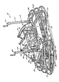
図1〜図6に示すように、本発明の好ましい一実施例における乗用コンクリート仕上げトロエル20は、剛性金属フレーム22と、このフレーム22上の上方デッキ24と、このデッキ24上に設けた運転者プラットフォームまたはペデスタル26と、上記デッキ24から下方に延び、仕上げるべき面上に仕上げトロエル20を支持するための左右のロータアセンブリ28及び30とを主として有する。ロータアセンブリ28及び30は仕上げ操作を行なうため夫々半時計方向及び時計方向に回転する。従来既知のリングガード32をトロエル20の外周に配置し、デッキ24から仕上げるべき面近くに延ばす。ペデスタル26をデッキ24の中心部後方に位置せしめ、運転者のシート34を支持せしめる。ペデスタル26とシート34はヒンジ(図示せず)を介して枢支し、エンジン72のような下方に位置する構成部品に近づき得るようにする。図1に示すようにペデスタル26の右側に燃料タンク36を配置し、左側に防水剤タンク38を配置し、後述する操縦システム76のアクチュエータ86の1つをその下側に配置する。
【0025】
図2と図5に示すように、リフトケージアセンブリ40をペデスタル26とシート34の下側でデッキ24の上面に設ける。このリフトケージアセンブリ40は、前方及び後方の水平管42と44と、この両端部に夫々位置され、上記水平管42と44をデッキ24から上方に離間せしめるための垂直支持管46とを含む複数の鋼管により構成する。上記水平管42と44は、フック等を受容する中心持ち上げ位置を特定するためのD−形切り欠き50を形成した板48によって互いに連結する。切り欠き50はトロエル20全体を持ち上げ得る所望の位置に形成し、その結果輸送のためのこの種の型の装置を持ち上げるために通常用いられるハーネスまたは4点型アタッチメントを不要とする。
【0026】
図3〜図5に示すように、各ロータアセンブリ28または30には、ギヤボックス52と、このギヤボック52から下方に延びる被動軸54と、半径方向支持アーム58を介して被動軸54によって支持せしめた、コンクリート面によって支持されるよう被動軸54の下端から半径方向外方に延びる円周方向に互いに離間された複数のブレード56とを有せしめる。各ギヤボックス52は、後述する理由でデッキ24に対して傾斜できるようデッキ24の下側に設ける。
【0027】
各ロータアセンブリ28と30のブレード56のピッチは、図1〜図4に示すブレードピッチ調節アセンブリ60によって個々に調節せしめる。各ブレードピッチ調節アセンブリ60は、垂直ポスト62と、この垂直ポスト62の頂部に設けたクランク64とを有し、ブレード56のピッチを変えるため運転者によって上記クランク64を回動せしめる。代表的な構成では、スラストカラー66をヨーク68に協働せしめ、被動軸54の軸に対し直角に延びる軸の周りでブレード56を回動する位置にスラストカラー66をヨーク68によって押圧せしめる。引張ケーブル70をクランク64からポスト62を通してヨーク68に延ばす。クランク64を回してヨーク68の傾斜角度を調節し、スラストカラー66を上下せしめればトロエルブレードのピッチを調節することができる。この型のブレードピッチ調節アセンブリを有するパワーコンクリート仕上げトロエルは米国特許第2,887,934号明細書に示されている。
【0028】
ロータアセンブリ28と30及び仕上げトロエル20の他の構成部分は運転者シート34の下側に設けたガソリンエンジン72によって駆動せしめる。エンジン72のサイズはトロエル20のサイズ及びエンジンによって駆動されるロータアセンブリの数によって変える。48インチの2つのロータアセンブリの場合には約25馬力のエンジンを用いる。ロータアセンブリ28と30は、図15〜図17に示す独特のトルク伝達システム74を介してエンジン72に連結し、独特の操縦システム76を介して操縦の目的で傾斜せしめる。操縦システム76とトルク伝達システム74を以下説明する。
【0029】
(3.操縦システム)
【0030】
この型の代表的な乗用コンクリート仕上げトロエルにおいては、ロータアセンブリ28と30の一部または全部を傾斜し、ブレード56の回転により水平力を作りトロエルを前進せしめるようにしている。操縦方向はロータアセンブリの傾斜方向と直角となる。即ち、ロータアセンブリを左右及び前後に傾斜すれば、トロエル20は前後及び左右に夫々動くようになる。操縦のために望まれる最も迅速な傾斜手段は、ギヤボックス52を含むロータアセンブリ28と30を全体として傾斜せしめることである。ギヤボックス52全体を傾斜せしめる好ましい実施例の内容は同様にして操縦制御のためロータアセンブリ28と30の他の構成部分をも傾斜せしめるシステムに適用できる。
【0031】
即ち、各ロータアセンブリ28と30の内側ブレード上の圧力が増加するようにギヤボックス52を横方向に傾斜すれば、トロエルが前進されるようになり、各ロータアセンブリ28と30の外側ブレード上の圧力が増加するようにギヤボックス52を横方向に傾斜すればトロエル20が後進するようになる。左右方向操縦のためには1つのみのギヤボックス、例えば右側ロータアセンブリ28のギヤボックス52を傾斜することが望まれ、ギヤボックス52を前方へ傾斜してロータアセンブリ28の前方ブレード上の圧力を増加すればトロエル20が右方に操縦される。同様にして、ギヤボックス52を後方へ傾斜してロータアセンブリ28の後方ブレード上の圧力を増加すればトロエル20が左側に操縦される。
【0032】
操縦システム76は、コントローラ85によって制御された左右の操縦アセンブリ80と82を用いて左右のロータアセンブリ28と30のギヤボックス52を傾斜せしめる。図5〜図9に示すように操縦アセンブリ80には、第1のアクチュエータ装置と、これをロータアセンブリ28のギヤボックス52に結合する第1の操縦リンケージ88とを設ける。同様にして図10〜図12に示すように操縦アセンブリ82には、第2のアクチュエータ装置と、これをロータアセンブリ30のギヤボックス52に結合する第2の操縦リンケージ92とを設ける。第1のアクチュエータ装置には前/後アクチュエータ84と、左/右アクチュエータ86とを有せしめ、一方、第2のアクチュエータ装置には前/後アクチュエータ90のみを設ける。コントローラ85は好ましくはアクチュエータ84,86,90に結合し、特定方向におけるコントローラ85の操縦によりトロエル20が同一方向に、好ましくはコントローラの移動速度に比例した速度で移動できるようにする。
【0033】
アクチュエータ84,86,90はコンクリート仕上げトロエル20のデッキ24を通して垂直に延ばし、図2〜図5に示すように例えばデッキ24及びまたはリフトケージアセンブリ40に対するアタッチメントによってフレーム22に直接または間接に取り付ける。各アクチュエータは、電気的に操作される部材とし、コントローラ85からの電気的操縦指令信号によって選択的に付勢し、関連する操縦リンケージ88または92を傾斜せしめる。アクチュエータ84,86,90は好ましくは、コントローラ85によって指令された位置とアクチュエータの実際の位置を比較する内部帰還ポテンショメータを有する型のものとする。これらの位置が合致したとき、アクチュエータの動作を停止し、その位置に保持せしめる。好ましいアクチュエータには、例えばワーナー エレクトリック オブ サウス ベロット ILから得られるボールねじアクチュエータを有せしめる。これらのアクチュエータは双方向、多目的、低コスト、帰還制御のものとする。各アクチュエータ84,86または90は1)デッキ24上に延び、デッキまたはトロエル20の他の固定部材に固定される固定ベース94と、2)電動機96と、3)直線変位可能なロッド98とを有する。ロッド98は、正確な位置決めと大負荷を移動可能なボールねじ駆動手段によって駆動する。例えば、この型のアクチュエータは毎秒49インチ迄のサドル速度と900ポンド迄の駆動軸負荷を処理できる。好ましいアクチュエータは略500ポンドの力を有する。操縦リンケージ88と92をより複雑なレバーアセンブリに代えた場合にはより軽負荷用のアクチュエータを用い得る。然しながら、本発明においてはボールねじアクチュエータ以外の他の電動アクチュエータを用いても良い。
【0034】
左右の操縦リンケージ88と92を以下説明する。
【0035】
図3,図5〜図9に示すように操縦リンケージ88は、操縦ブラケット100と、2軸枢支のためデッキ24上に操縦ブラケット100を取り付ける枢支支持アセンブリとを含む。この枢支支持アセンブリは、第1,第2の各対のピローブロック軸受102,110と、クロス管104とを有する。第1の対のピローブロック軸受102はデッキ24の底にボルト付けする。クロス管104は、1)ピローブロック軸受102内に挿入される長手方向両端部106と、2)第2の対のピローブロック軸受110に隣接される横方向両端部108とを有する。操縦ブラケット100にはトロエル20の長手方向に延びる、フレーム112と、このフレーム112から横方向に延びる一対の取付板114とを有せしめる。操縦ブラケット100とギヤボックス52は、第2の一対のピローブロックの軸受110に対し、ピローブロック110内の孔と、取付板114の孔とを通りギヤボックス52の頂部のねじ孔に螺合されるボルト116によって固定せしめる。この構成により操縦ブラケット100(従って、ギヤボックス52)が1)クロス管104の横方向の軸の周りに回動しギヤボックスが前後に傾斜して右/左操縦がなされ、2)クロス管の長手方向の軸の周りに回動してギヤボックスを左右に傾斜せしめ、従って前/後操縦制御がなされるようにする。この実施例においては、フレーム112の対向端が図3に示すようにブレードピッチ調節ポスト62のための取付板122を構成し、ブレードピッチ調節アセンブリ60がギヤボックス52と共に移動し、従って操縦制御操作がブレードピッチに影響しないようになる。ギヤボックスをクロス管の横方向軸の周りに回動せしめるため、前/後アクチュエータ84を枢支ピン128を介して枢支レバー126のクレビス124に連結せしめる。レバー126を第2の対のピローブロック軸受110と、クロス管104の横方向端部108を通して延ばし、抑止リング130によって保持する。
【0036】
図2,図4,図5,図10〜図12に示すように、操縦アセンブリ82に対して操縦アセンブリ80は、前/後操縦操作のため左右に回動することを除いて同一構造とする。即ち、アクチュエータ86に沿う操縦リンケージ92の長手方向端のクレビスを省略する。更に、第2の対の軸受110を単純な支え150に代えることができる。操縦リンケージ92は操縦リンケージ88と同一とし、操縦ブラケット140と枢支支持アセンブリとを有せしめる。枢支支持アセンブリには、1)ピローブロック軸受142と、2)クロス管144の長手方向端部146と横方向端部148とを有せしめる。操縦ブラケット140にはフレーム152と、このフレーム152から横方向に延びる一対の取付板154とを有せしめ、この取付板154はボルト156によって支え150とギヤボックス156に連結せしめる。関連するブレードピッチ調節アセンブリ60のポスト62をフレーム152の一端に設けた取付板162上に取り付ける。前/後アクチュエータ90を枢支ピン168を介して枢支レバー166のクレビス164に連結せしめる。この枢支レバー166を支え150と、クロス管144の横方向端部148を通して延ばし、支え150にスプリングピン172によって固定し、この結果、ギヤボックス52とフレーム22がクロス管144の長手方向の軸の周りに左右に回動できるが、横方向軸の周りに前後には回動できないようにする。
【0037】
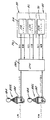
コントローラは物理的な操作量を電子操縦指令信号に変化する。図13に示すように、好ましいコントローラ85を、プログラムされたCPU180を介してアクチュエータに電子的に接続された2軸比例制御ジョイステックにより構成し、操縦指令信号を作りこれをアクチュエータ84,86,90に送るようにする。アクチュエータ84,86,90からの帰還信号をCPU180に戻し、アクチュエータ動作をジョイステック動作に関連せしめる。この結果、アクチュエータ84,86または90をジョイステック動作の大きさに比例して指令された方向に移動せしめる。従ってトロエル20はジョイステックの移動量に比例した速度でジョイステックの移動方向に移動する。例えば、コンクリート仕上げトロエル20を前進せしめるときは、ジョイステックを前後軸の周りに前方に回動すれば、CPU180が前/後アクチュエータ84と90の出力ロッドをジョイステックの動作に比例して制御し、ギヤボックス52を互いに左右方向に回動し、トロエル20がジョイステックの動作に比例した速度で前方または後方に移動されるようにする。同様にしてジョイステックを第2軸の周りで左右に傾斜せしめれば、操縦指令信号が発生し、この信号がCPU180によって処理され、左右アクチュエータ86上の帰還ポテンショメータに協働してアクチュエータ86の出力ロッドを伸縮し、関連するギヤボックス52をジョイステックの移動量に比例する量だけ前後に傾斜し、その結果、仕上げトロエルがジョイステックの移動量に比例した速度で左右に移動されるようにする。ジョイステックを釈放すれば、内部バイアススプリング(図示せず)によって中心または中立位置に戻され、各アクチュエータ84,86,90が同じく中立位置に復帰されるようにする。
【0038】
図13に示すように、ジョイステックには固定ベース182と、この固定ベース182に傾動自在に取り付けたグリップ184とを有せしめる。ロッカースイッチ186をグリップ184上に設け、前/後アクチュエータ84と90を同時に且つ反対方向に付勢するためロッカースイッチ186を押したとき、その変位方向に応じてトロエル20が時計方向または半時計方向に回転されるようにする。好ましくは、ロッカースイッチ186を右方に傾斜したときトロエル20が時計方向に回転し、左方に傾斜したとき反時計方向に回転されるようにする。
【0039】
他の実施例においては、図13に示す単一の2軸ジョイステックの代りに図14に示すように2個のジョイステック85Rと85Lを用い、一方のジョイステック85Rを前/後及び左/右操縦制御のために好ましい2軸ジョイステックとし、他方85Lを前/後操縦制御のみ可能な前後にのみ傾動可能な単軸ジョイステックとする。この実施例ではロッカースイッチを省略せしめる。ある運転者には、この実施例のものが各ロータアセンブリ制御のために従来用いられている機械的レバーに類似している理由で好まれる。
【0040】
上記パワー操縦システム76には、従来の機械的に操作されるシステムや流体的に操作されるシステムにまさる幾つかの利益がある。例えば、本発明システムによればジョイステックをその内部スプリング力にまさる1〜2ポンド程度の僅かな力で操作でき、従って、従来の機械的操作システムよりその操作がより容易となる。また、ギヤボックス52にアクチュエータ84,86,90を結合するための機械的リンケージが従来の機械的操作制御レバーの場合よりより単純である利点がある。更に、流体的操縦システムと異なり、トロエル20は軽量であり、また、高圧流体漏れの恐れがない。
【0041】
(4.トルク伝達システム)
【0042】
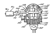
図15〜図18に示すように、トルク伝達システム74によってエンジン72の出力軸200からギヤボックス52の被動軸202に対し駆動トルクを伝達し、ロータアセンブリ28と30を回転せしめる。このトルク伝達システム74には、1)トロエル20によって異なる仕上げ操作を行なうため変速比及びまたはブレードアセンブリ直径を変え得ること、2)エンジン出力軸200に対するギヤボックス52の被動軸202の傾斜を調節しながら複雑なユニバーサルジョイントを不要ならしめ得ることが必要である。このため1)図16に示す可変速トルクコンバータアセンブリ204と、2)図17に示す可撓性駆動軸206とを夫々用いる。
【0043】
トルクコンバータアセンブリ204には互いにベルト212のようなトルク伝達素子によって結合した可変速駆動及び被動クラッチ208と210を有せしめる。図16に示すように駆動クラッチ208のハブ214はエンジン72の出力軸、またはエンジンの出力軸に直接または間接に接続された他の出力軸の何れかであるエンジン出力軸200にキー止めする。同様にして被動クラッチ210のハブ216をジャッキ軸218にキー止めし、被動クラッチ210によってジャッキ軸218を回動せしめる。ジャッキ軸218をピローブロック軸受220によってフレーム22上に支持し、出力端222を対応する左または右の可撓性駆動軸206に結合する。
【0044】
可撓性駆動軸206をジャッキ軸218と、ギヤボックス52の被動軸202に接続する。図17に示すように各可撓性駆動軸206は、対応する軸受220を通るカップリング226を介してジャッキ軸218に関連する出力端部222に固定する。各カップリング226の入力端部は関連するジャッキ軸218の出力端部222にキー止めし、各カップリング226の出力端部は関連する可撓性駆動軸206の入力端部に取り付けた接手224にボルト付けする。各可撓製駆動軸206の出力端部に取り付けた他の接手228をこれにボルト付けした内側スプラインカップリング230によって関連するギヤボックス被動軸202に結合する。このスプラインカップリング230はギヤボックスが傾動する間可撓性駆動軸206とギヤボックス被動軸202間の相対的軸方向移動を許容する。必要に応じて、可撓性駆動軸206とジャッキ軸218間の軸方向移動を上記相対的移動によって許容せしめる。
【0045】
上述のように、ジャッキ軸218に相対的に左右のギヤボックス52を傾斜せしめるため軸206として可撓軸を用いれば複雑なユニバーサルジョイントが不要となる。関連するギヤボックス52の被動軸を駆動するために十分なねじり剛性を各軸206に有せしめながら各軸206の長さの少なくとも一部、例えば端部を湾曲できる材料で作る。ギヤボックス52は10°以下、例えば4°程度、僅かに傾斜するのみであるから軸206は大きく湾曲する必要はない。然しながら、可撓軸を用いる多くの場合とは異なり、軸206は、トロエル20の操作の間、即ちトルク伝達の間動的に繰り返し湾曲することになる。草刈機や、駆動モータと被動軸間に湾曲伝達路を形成する他の装置に多く用いられる巻線状の可撓軸は、この目的に好適である。この実施例の軸は長さ1フィート,直径1インチである。必要に応じてゴムや耐水,耐塵材料のスリーブ232を巻線状可撓軸の周りにその保護のため嵌合せしめる。好ましい巻線状可撓軸は例えばニューヨーク市、ビンガムトンのエリオット マニファクチュアリング カンパニー から得られる。
【0046】
トルクコンバータアセンブリ204としては、例えばコメットインダストリィから得られる可変速型のものが好ましい。図16と図17に示すように、駆動クラッチ208には上記ハブ214と可変幅シーブ240を有せしめる。このシーブ240にはハブ214に固定した第1部分242とハブ214に摺動自在に設けた第2部分244とを有せしめ、上記第2部分244を第1部分242から軸方向に離接自在ならしめる。第2部分244をスプリング(図示せず)によって第1部分242から常時引き離し、複数の遠心力カム246の作用によって第1部分242に向って軸方向に移動されるようにする。第1及び第2部分242と244の軸方向内側面は内側から外側に向って外方に傾斜せしめ、その結果、シーブ240上のベルトと同一幅部分に対応する実効直径が、第1,第2部分242と244間の軸方向間隔に反比例して変るようにする。従って、エンジン出力軸200速度が増加したとき遠心力カム246が第2部分244を第1部分242に向って押し、シーブ240の実効軸方向の幅が減少する。従って、シーブ240の実効直径は増加し、図16の矢印248に示すようにベルトがシーブに沿って上方に移動する。
【0047】
駆動クラッチ210にはその直径が駆動クラッチ208のシーブ240の直径に反比例して変化する可変直径シーブ250を設ける。このシーブ250にはハブ216に固定した第1部分252と、この第1部分252に離接するよう軸方向に移動自在な、ハブ216に設けた第2部分254とを有せしめる。この第2部分254はスプリング256によって第1部分252に向って常時抑制せしめる。第1及び第2部分252と254の軸方向内側面は内側から外側に向って外方に傾斜せしめ、その結果、シーブ250の実効直径が、第1,第2部分252と254間の軸方向間隔に反比例して変るようにする。従って、エンジンが加速され駆動クラッチ208のシーブ240に沿ってベルト212が外方に移動したとき、増加した張力によってスプリング256を圧縮し、第1,第2部分252と254間の軸方向間隔が広がり、被動シーブ250の実効直径が減少されるようにする。この結果、図16に示す矢印258の方向にベルト212が内側に移動されるようにする。従って、トルクコンバータアセンブリ204の実効速度比がエンジン速度増加につれて次第に増加し、エンジン速度減少につれて次第に減少するようになる。このため、ロータアセンブリ28と30はエンジン速度によって大きく変化する速度/トルク範囲で駆動されるようになる。
【0048】
本発明によれば、同一のトロエルを用いて後述のオーバーラップ及び非オーバーラップの両モードで操作できる利点がある。即ち、図18,図18A,図19,図19Aに示すように、トロエルブレード56を、支持アーム58に沿って軸方向に離間した孔262を通して延びブレード56のためのブラケット266に設けたねじ孔264に螺合したボルト260によって関連する支持アーム58に取り付ける。支持アーム58は十分に長くし、且つ十分な数の孔262を設け、ブレード56をアーム58の任意の点に固定でき、従って、ブレード56を1)図18及び図18Aに示すようにロータアセンブリ28と30のブレード56の外端が画く円弧C1とC2が互いに重ならないようにし、または2)図19及び図19Aに示すように円弧C1とC2が一部重なるようにする。ブレード56を図18と図18Aに示すようにオーバーラップしない配置としたとき、各ロータアセンブリ28と30のブレード56の底に円形パン(図示せず)を留め、トロエル20を浮動操作できるようにする。
【0049】
仕上げトロエル20は任意の仕上げ操作に用い得る。例えば、コンクリートを十分に仕上げるに際し、新たに注入されたコンクリートを粗仕上げするための“浮動”操作を行なうためブレード56を支持アーム58に取り付け、図18と図18Aに示すように各ブレード56のセットが画く円弧C1とC2が重ならないようにし、パン(図示せず)を各ロータアセンブリ28または30のブレード56に取り付け、トロエル20をエンジン72と共に低速でコンクリート面上を移動せしめる。この場合、トルクコンバータアセンブリ204の駆動及び被動クラッチ208と210のシーブ240と250は夫々最小及び最大直径またはそれに近い状態となり、最大速度変化が達成される。この結果、50rpm以下、例えば30rpmの低回転速度で高トルクがブレードに伝達される。他の例においては、図19と図19Aに示すように支持アーム58に沿ってブレード56を上記円弧C1とC2が互いに重なるように位置できる。
【0050】
【発明の効果】
上記のように本発明によれば運転者はトロエル20を異なるエンジン速度と異なるブレードピッチでコンクリート面上を移動できる。トルクコンバータアセンブリ204の速度比はエンジン速度が増加したとき増加し、ロータアセンブリ28と30を従来以上に高速で駆動できる。仕上げトロエル20は、ブレードピッチが最大でブレード56が150rpm以上、好ましくは約200rpmの回転速度である。“バーニング操作”においても使用できる。したがって、単一のコンクリート仕上げトロエル20は、極低速/高トルク浮動操作と極高速バーニング操作を含む全仕上げ操作のために使用でき、同一ブレード56を互いに重なる及び重ならない仕上げ操作のため用いることができる。従来の装置ではこのような自由度は得られない。
【0051】
ギヤボックス52は所望の操縦制御を達成するため仕上げ操作の間殆んど連続して傾斜される。この傾斜により可撓性軸206の曲げが繰り返される。この軸206のメンテナンスは驚くほど容易であり、ユニバーサルジョイントに比べて寿命が極めて長く、ウエットコンクリートによってダメージを受ける事がない。
【図面の簡単な説明】
【図1】本発明の乗用コンクリート仕上げトロエルの一実施例を示す斜視図である。
【図2】運転者用シートとこれに隣接する部分を削除して示す図1のトロエルの斜視図である。
【図3】図1に示すトロエルの左側面図である。
【図4】図1に示すトロエルの右側面図である。
【図5】図2に示すトロエルの背面図である。
【図6】左側のロータアセンブリの分解斜視図である。
【図7】図6に示すロータアセンブリの正面図である。
【図8】図6に示すロータアセンブリの右側面図である。
【図9】図6に示すロータアセンブリの平面図である。
【図10】右側のロータアセンブリの分解斜視図である。
【図11】図10に示すロータアセンブリの平面図である。
【図12】図10に示すロータアセンブリの右側面図である。
【図13】本発明の一実施例における操縦制御システムのブロック線図である。
【図14】本発明の他の実施例における操縦制御システムのブロック線図である。
【図15】トルク伝達システムの側面図である。
【図16】図15のシステムの一部の平面図である。
【図17】図15のシステムの分解斜視図である。
【図18】本発明のトロエルの非オーバーラップ状態における底面図である。
【図18A】図18の一部の拡大図である。
【図19】本発明のトロエルのオバーラップ状態における底面図である。
【図19A】図19の一部の拡大図である。
【符号の説明】
20 乗用コンクリート仕上げトロエル
22 剛性金属フレーム
24 デッキ
26 ペデスタル
28 ロータアセンブリ
30 ロータアセンブリ
32 リングガード
34 シート
36 燃料タンク
38 防水剤タンク
40 リフトケージアセンブリ
42 水平管
44 水平管
46 垂直支持管
48 板
50 切り欠き
52 ギヤボックス
54 被動軸
56 ブレード
58 支持アーム
60 調節アセンブリ
62 垂直ポスト
64 クランク
66 スラストカラー
68 ヨーク
70 ケーブル
72 エンジン
74 トルク伝達システム
76 操縦システム
78 操縦システム
80 操縦アセンブリ
82 操縦アセンブリ
84 アクチュエータ
85 コントローラ
86 アクチュエータ
88 操縦リンケージ
90 アクチュエータ
92 操縦リンケージ
94 固定ベース
96 電動機
100 操縦ブラケット
102 ピローブロック軸受
104 クロス管
106 端部
108 端部
110 ピローブロック軸受
112 フレーム
114 取付板
116 ボルト
124 クレビス
126 レバー
128 枢支ピン
130 抑止リンク
140 操縦ブラケット
142 軸受
144 クロス管
146 端部
148 端部
150 支え
152 フレーム
154 取付板
156 ギヤボックス
162 取付板
164 クレビス
166 枢支レバー
168 枢支ピン
172 スプリングピン
180 CPU
182 固定ベース
184 グリップ
186 ロッカースイッチ
200 出力軸
202 被動軸
204 可変速トルクコンバータアセンブリ
206 可撓性駆動軸
208 可変速駆動クラッチ
210 被動クラッチ
212 ベルト
214 ハブ
216 ハブ
218 ジャッキ軸
220 軸受
222 出力端
224 接手
226 カップリング
228 接手
230 スプラインカップリング
232 スリーブ
240 可変幅シーブ
242 第1部分
244 第2部分
246 カム
248 矢印
250 可変直径シーブ
252 第1部分
254 第2部分
256 スプリング
258 矢印
260 ボルト
262 孔
264 孔
266 ブラケット[0001]
BACKGROUND OF THE INVENTION
The present invention relates to a concrete finishing trowel and a method of operating the same, and more particularly to a concrete finishing trowel using one or more rotor assemblies having rotating blades for finishing a concrete surface and a method of operating the same.
[0002]
[Prior art]
Various devices are used to smooth wet concrete. These devices also include several large hand-guided devices and self-propelled finishing trowels, including relatively large two or three roller devices, hand-guided finishing troels and simple hand trowels. A self-propelled finishing trowel, in particular, a riding finishing trowel, can finish a large portion of concrete faster and more efficiently than a hand-finished finishing trowel. The present invention relates to a self-propelled finishing trowel, and an example of a riding finishing trowel will be described below.
[0003]
A typical riding concrete finish trowel has a frame that includes a deck. At least two or three rotor assemblies are mounted under the deck. Each rotor assembly has a driven shaft extending downward from the deck and a plurality of trowel blades extending radially outward from a lower end of the driven shaft and supported by a surface to be finished. The driven shaft of the rotor assembly is provided on the frame and is driven by one or more built-in engines linked to the driven shaft by a corresponding rotor assembly gearbox. The finishing trowel and the driver's weight are frictionally transmitted to the concrete via the rotating blade, and the concrete surface is smoothed. In order to change the pitch of the blades, tilting the individual blades by manipulating the mechanical lever and linkage system accessible by the driver on the platform will change the force applied by the weight to the surface to be finished. Changing the pitch of the blade will change the finishing characteristics of Troel. For example, in an ideal finishing operation, a “floating” state in which the blade is operated at a high torque and a low speed of about 30 rpm is first set. The concrete is then aged for 15-30 minutes, then the speed and blade pitch are gradually increased to finish or “burning” at maximum speed, preferably about 150-200 rpm.
[0004]
The blade of a riding trowel can be tilted independently of pitch control for steering purposes. By tilting the driven shaft of the rotor assembly, the force applied to the concrete surface by the rotating blade acts to advance the trowel in a direction perpendicular to the tilted direction of the driven shaft. In other words, if the driven shaft of the rotor assembly is tilted left and right and front and rear, the trowel moves forward and backward and left and right, respectively. In the example in which the riding trowel has two rotor assemblies, the driven shafts of both rotor assemblies need to be tilted back and forth, but the driven shaft of one rotor assembly needs to be able to tilt left and right.
[0005]
The most common steering assembly is mechanically operated. These assemblies typically have two steering control levers located adjacent to the driver's seat, each accessible by the driver's left and right hands. These levers are mechanically coupled to the pivotal gearbox of the associated rotor assembly via a preferred mechanical linkage assembly. In order to incline the gear box left and right and front and rear, respectively, the trowel is steered by tilting the lever back and forth and left and right. This type of steering assembly is shown in U.S. Pat. Nos. 4,046,484 and 5,108,220.
[0006]
[Problems to be solved by the invention]
The mechanically operated steering control assembly of the type shown in the above patent is difficult to operate because it requires a large physical force applied by the driver. It is necessary to apply a force of 20 to 40 pounds to a typical steering control lever for front-back and left-right steering. Many drivers become inoperable when such power is applied for several hours without break. In addition, applying ergonomic force to the left and right causes greater fatigue than applying force to the front and rear.
[0007]
It has been proposed to improve the mechanical operation steering control assembly of conventional concrete finishing equipment having a power assembly. For example, Whiteman Industries, Inc. of Carson, Calif., USA, manufactures a fluidly controlled riding trowel under the trade name “HTS-Series”. The device is fluidly driven by a fluid pump driven by the engine. The fluid pump supplies pressurized fluid to the fluid motor of the rotor assembly and the fluid steering cylinder for tilting the driven shaft of the rotor assembly. The steering assembly is controlled by a joystick provided on the platform adjacent to the driver seat. These joysticks are easier to operate than conventional mechanical levers. Therefore, less fatigue than a driver of a conventional mechanical control device.
[0008]
Compared to mechanical controls, fluid-controlled concrete finish trowels are superior in several respects, but have some drawbacks. For example, fluid pumps, fluid motors, steering cylinders, and associated fluid devices are very heavy. Therefore, even if the blade pitch is minimized to distribute the equipment weight over a large area, a longer concrete setting time is required before the so-called “floating” finishing operation is first performed. This delay makes it possible to prevent the finishing operation because it causes the concrete finishing time to be lost. Furthermore, complex fluid systems required by hydrostatic steering devices tend to leak. Oil leakage to new concrete is undesirable. Furthermore, hydrostatic controls are more expensive than manual controls because they require relatively large and expensive fluid motors, valves, and the like.
[0009]
Accordingly, there is a need for a self-propelled finishing trowel having a steering control assembly that is relatively light, inexpensive, and automatically operable compared to mechanical and hydrostatic controls.
[0010]
The first main object of the present invention is to obtain a self-propelled finishing trowel which cooperates with a relatively simple, lightweight and inexpensive power steering system.
[0011]
Another object of the present invention is to obtain a self-propelled concrete finish trowel which meets the first main object and at least reduces driver fatigue.
[0012]
Another object of the present invention is to obtain a concrete finish trowel which meets the first main object and does not require high pressure fluid for its operation and therefore has no fluid leakage problems.
[0013]
The second main object of the present invention is to obtain a method for maneuvering a self-propelled concrete finishing trowel that requires less force applied by the driver and is therefore free from fatigue.
[0014]
Another object of the present invention is to obtain a method that meets the second object and does not use a heavy, complex leaky fluid system.
[0015]
[Means for Solving the Problems]
The first main object of the present invention can be achieved by manipulating a concrete finishing device using an electronic actuator, such as a ball screw actuator, without using a mechanical lever system or fluid system. This actuator is indirectly controlled by a controller such as an electronic joystick, and when energized, at least the driven shaft of the rotor assembly is tilted to perform the desired maneuver.
[0016]
Preferably, the actuator of the actuator device associated with each rotor assembly is connected to the rotor assembly by a relatively simple steering linkage directly connected to the assembly gearbox. In a typical example of a riding trowel having two rotor assemblies, two actuators and a two-axis pivot steering linkage allow left and right and front and rear steering controls to be performed for one of the rotor assemblies. On the other hand, one actuator and its associated single axis pivot steering linkage allows for forward and backward steering control for the other rotor assembly.
[0017]
The controller converts the driver's physical motion into an electronic steering command signal. For example, the controller may have one or more joysticks, preferably proportional control joysticks, that are electronically coupled to the actuator, and when the actuator is energized, the feedback circuit will change the position of the joystick. Compared with the position, the actuator is continuously energized until the position of the actuator matches the command position determined by the joystick position. When the joystick is released, the actuator will automatically return to its center position. Due to the characteristics of the feedback circuit between the joystick and the corresponding actuator, the moving speed of the trowel on the surface to be finished is directly proportional to the magnitude of the joystick movement, and the trowel is moved in the joystick moving direction. Since the force applied by the driver is very small, the driver's driving fatigue can be greatly reduced compared to conventional mechanical control trowels.
[0018]
Other objects and advantages of the present invention will be described in detail below with reference to embodiments shown in conjunction with the drawings, but the present invention should not be limited thereto. It goes without saying that the present invention can be variously increased or decreased without departing from the spirit of the present invention.
[0019]
DETAILED DESCRIPTION OF THE INVENTION
[0020]
(1. Resume)
[0021]
In the present invention, a self-propelled concrete finishing trowel is constructed having an improved power steering system that can steer the trowel by tilting the axis of the rotor assembly without the need for operating forces that tire the driver. The steering control system includes at least one electrical actuator, such as a ball screw actuator, coupled to each rotor assembly and controlled by a controller operated by a driver. Preferably, the controller has at least one, preferably two joysticks, and the joystick is operated by the driver to move the trowel in the joystick movement direction at a speed proportional to the amount of joystick movement. Try to squeeze. A typical example of manipulating the trowel by rotating the gear box of at least one rotor assembly about two axes uses separate actuators to rotate the gear box. This Troel is easy to operate, lightweight and has little risk of high pressure fluid leakage.
[0022]
(2. Overview)
[0023]
The present invention is applicable to any power concrete finishing trowel that is steered by tilting the rotor assembly. For example, the present invention will be described with reference to a riding finish trowel having two rotor assemblies that rotate in opposite directions, but is not limited thereto.
[0024]
As shown in FIGS. 1 to 6, a riding
[0025]
As shown in FIGS. 2 and 5, a
[0026]
As shown in FIGS. 3 to 5, each
[0027]
The pitch of the
[0028]
The
[0029]
(3. Control system)
[0030]
In a typical riding concrete finishing trowel of this type, some or all of the
[0031]
That is, if the gearbox 52 is tilted laterally so that the pressure on the inner blades of each
[0032]
The
[0033]
The
[0034]
The left and
[0035]
As shown in FIGS. 3-5, the
[0036]
As shown in FIGS. 2, 4, 5, and 10 to 12, the steering
[0037]
The controller changes the physical operation amount into an electronic control command signal. As shown in FIG. 13, the
[0038]
As shown in FIG. 13, the joystick has a fixed
[0039]
In another embodiment, instead of the single two-axis joystick shown in FIG. 13, two
[0040]
The
[0041]
(4. Torque transmission system)
[0042]
As shown in FIGS. 15 to 18, the
[0043]
[0044]
The
[0045]
As described above, if a flexible shaft is used as the
[0046]
The
[0047]
The
[0048]
According to the present invention, there is an advantage that it is possible to operate in both an overlap mode and a non-overlap mode described later using the same trowel. That is, as shown in FIGS. 18, 18A, 19, and 19A, the
[0049]
The finishing
[0050]
【The invention's effect】
As described above, according to the present invention, the driver can move the
[0051]
The gear box 52 is tilted almost continuously during the finishing operation to achieve the desired steering control. The bending of the
[Brief description of the drawings]
FIG. 1 is a perspective view showing an embodiment of a riding concrete finishing trowel of the present invention.
2 is a perspective view of the trowel shown in FIG. 1 with a driver's seat and a portion adjacent to the driver's seat removed. FIG.
3 is a left side view of the trowel shown in FIG. 1. FIG.
4 is a right side view of the trowel shown in FIG. 1. FIG.
5 is a rear view of the trowel shown in FIG. 2. FIG.
FIG. 6 is an exploded perspective view of a left rotor assembly.
7 is a front view of the rotor assembly shown in FIG. 6. FIG.
FIG. 8 is a right side view of the rotor assembly shown in FIG. 6;
FIG. 9 is a plan view of the rotor assembly shown in FIG. 6;
FIG. 10 is an exploded perspective view of the right rotor assembly.
FIG. 11 is a plan view of the rotor assembly shown in FIG. 10;
12 is a right side view of the rotor assembly shown in FIG.
FIG. 13 is a block diagram of a steering control system in one embodiment of the present invention.
FIG. 14 is a block diagram of a steering control system according to another embodiment of the present invention.
FIG. 15 is a side view of the torque transmission system.
16 is a plan view of a portion of the system of FIG.
17 is an exploded perspective view of the system of FIG.
FIG. 18 is a bottom view of the Troel of the present invention in a non-overlapping state.
18A is an enlarged view of a part of FIG.
FIG. 19 is a bottom view of the Troel of the present invention in the overwrap state.
FIG. 19A is an enlarged view of a part of FIG.
[Explanation of symbols]
20 Passenger concrete finish Troel
22 Rigid metal frame
24 decks
26 Pedestal
28 Rotor assembly
30 Rotor assembly
32 Ring guard
34 seats
36 Fuel tank
38 Waterproofing agent tank
40 Lift cage assembly
42 Horizontal pipe
44 Horizontal tube
46 Vertical support tube
48 boards
50 cutout
52 Gearbox
54 Driven shaft
56 blades
58 Support arm
60 adjustment assembly
62 Vertical post
64 cranks
66 Thrust color
68 York
70 cable
72 engine
74 Torque transmission system
76 Maneuvering system
78 Maneuvering system
80 steering assembly
82 Steering assembly
84 Actuator
85 controller
86 Actuator
88 Steering linkage
90 Actuator
92 Steering linkage
94 Fixed base
96 electric motor
100 Steering bracket
102 pillow block bearing
104 Cross tube
106 end
108 end
110 pillow block bearing
112 frames
114 Mounting plate
116 volts
124 Clevis
126 lever
128 pivot pins
130 Deterrence link
140 Steering bracket
142 Bearing
144 Cross tube
146 end
148 edge
150 Support
152 frames
154 Mounting plate
156 Gearbox
162 Mounting plate
164 Clevis
166 Pivot lever
168 pivot pin
172 Spring pin
180 CPU
182 fixed base
184 grip
186 Rocker switch
200 Output shaft
202 Driven shaft
204 Variable Speed Torque Converter Assembly
206 Flexible drive shaft
208 Variable speed drive clutch
210 Driven clutch
212 belt
214 hub
216 hub
218 Jack shaft
220 Bearing
222 Output terminal
224 Joint
226 coupling
228 joint
230 Spline coupling
232 sleeve
240 variable width sheave
242 1st part
244 2nd part
246 cam
248 arrow
250 variable diameter sheave
252 1st part
254 second part
256 spring
258 arrow
260 volts
262 hole
264 holes
266 bracket
Claims (20)
(B)被動軸と、この被動軸から外方に延びるように設けられた、仕上げられるべき面によって支持され上記被動軸によって回転される複数のトロエルブレードとを有し、上記車体フレームに支持されるロータアセンブリと、
(C)上記車体フレームに相対的に移動したとき、上記ロータアセンブリの少なくとも一部を上記車体フレームに相対的に傾斜せしめるため上記ロータアセンブリに結合した操縦リンケージと、
(D)上記操縦リンケージに結合され、上記車体フレームに相対的に上記ロータアセンブリの上記一部を傾斜せしめるよう上記操縦リンケージを移動せしめるため選択的に付勢可能な電気的アクチュエータ装置と、及び
(E)上記車体フレームに相対的に上記ロータアセンブリの上記一部を傾斜せしめるよう上記電気的アクチュエータ装置を付勢するために用いる電気操縦指令信号を発生するよう選択的に操作される、上記アクチュエータ装置に電子的に接続された手動操縦コントローラと
より成り、上記電気的アクチュエータが、上記コントローラから上記電気操縦指令信号を受け取り、この信号に応じて上記乗用トロエルを操縦するよう上記被動軸を傾斜するため操作されることを特徴とする乗用コンクリート仕上げトロエル。(A) a body frame;
(B) having a driven shaft and a plurality of trowel blades that are provided so as to extend outward from the driven shaft and are rotated by the driven shaft and supported by the body frame. A rotor assembly,
(C) a steering linkage coupled to the rotor assembly to tilt at least a portion of the rotor assembly relative to the body frame when moved relative to the body frame;
(D) an electrical actuator device coupled to the steering linkage and selectively biasable to move the steering linkage to tilt the part of the rotor assembly relative to the body frame; E) The actuator device that is selectively operated to generate an electric steering command signal that is used to bias the electric actuator device to tilt the portion of the rotor assembly relative to the body frame. Ri more becomes electronically connected manual operation controller, the electrical actuator, receives the electrical operating control instruction signal from the controller, tilting the driven shaft so as to steer the riding trowel according to the signal Riding concrete finish trowel characterized by being operated for .
(A)上記第1ロータアセンブリから離間しており、上記車体フレーム上に支持された第2ギヤボックスと、第2被動軸と、上記第2被動軸と共に回転されるよう上記第2被動軸から外方に延びる、仕上げるべき面によって支持される複数のトロエルブレードとを含む第2ロータアセンブリと、
(B)(1)上記第2ギヤボックスに結合され、上記車体フレームに相対的に移動したとき、上記車体フレームに相対的に上記第2ギヤボックスを傾斜する第2操縦ブラケットと、及び
(2)上記第2操縦ブラケットに結合され、上記車体フレームに相対的に上記第2ギヤボックスを傾斜するよう上記第2操縦ブラケットを移動するため、選択的に付勢可能な第2電気的アクチュエータ装置とを含む第2操縦リンケージとを有する、
請求項2記載の乗用コンクリート仕上げトロエル。The finishing trowel is a riding trowel, and the rotor assembly and the steering linkage are a first rotor assembly and a first steering linkage, respectively. (A) is separated from the first rotor assembly, and is mounted on the body frame. A second gear box supported by the second driven shaft, a second driven shaft, and a plurality of trowel blades supported by a surface to be finished extending outwardly from the second driven shaft so as to be rotated together with the second driven shaft. A second rotor assembly comprising:
(B) (1) a second steering bracket that is coupled to the second gear box and tilts the second gear box relative to the body frame when moved relative to the body frame; and (2) A second electrical actuator device coupled to the second steering bracket and selectively biased to move the second steering bracket to tilt the second gear box relative to the body frame; A second steering linkage comprising
The riding concrete finish trowel according to claim 2.
を介し上記可動フレーム上に設けられている請求項5記載の乗用コンクリート仕上げトロエル。The second gear box is 1) a bearing set provided on the vehicle body frame, and 2) provided on the bearing set, coupled to the second gear box, and is used during front / rear steering operations. The riding concrete finishing trowel according to claim 5, wherein the riding concrete finishing trowel is provided on the movable frame via a control frame that tilts the second gear box to the left and right.
(A)コントローラを付勢して所望の操縦指令を示す電気信号を作る工程と、
(B)上記コントローラからの上記信号を電気的アクチュエータ装置に送る工程と、
(C)上記受け取った信号に応じて上記アクチュエータ装置を電気的に付勢し、上記仕上げトロエルを操縦するよう上記被動軸を傾斜せしめる工程と
より成る乗用コンクリート仕上げトロエルの操縦方法。A vehicle body frame, a driver's platform provided on the vehicle body frame, and at least one rotor assembly, the rotor assembly comprising: 1) a driven shaft extending downward from the frame; and 2) from the driven shaft A method of steering a riding finish trowel having a plurality of trowel blades provided to extend outward and supported by a surface to be finished and rotated by the driven shaft,
(A) energizing the controller to produce an electrical signal indicating a desired maneuvering command;
(B) sending the signal from the controller to an electrical actuator device;
(C) A method for operating a riding concrete finishing trowel comprising the step of electrically energizing the actuator device according to the received signal and tilting the driven shaft so as to operate the finishing trowel.
Applications Claiming Priority (2)
| Application Number | Priority Date | Filing Date | Title |
|---|---|---|---|
| US09/352,225 US6368016B1 (en) | 1999-07-13 | 1999-07-13 | Concrete finishing trowel having an electronically actuated steering assembly |
| US09/352225 | 1999-07-13 |
Publications (3)
| Publication Number | Publication Date |
|---|---|
| JP2001073313A JP2001073313A (en) | 2001-03-21 |
| JP2001073313A5 JP2001073313A5 (en) | 2004-11-25 |
| JP3953261B2 true JP3953261B2 (en) | 2007-08-08 |
Family
ID=23384280
Family Applications (1)
| Application Number | Title | Priority Date | Filing Date |
|---|---|---|---|
| JP2000206213A Expired - Fee Related JP3953261B2 (en) | 1999-07-13 | 2000-07-07 | Concrete finishing trowel and its operation method |
Country Status (9)
| Country | Link |
|---|---|
| US (1) | US6368016B1 (en) |
| EP (1) | EP1069259B1 (en) |
| JP (1) | JP3953261B2 (en) |
| AT (1) | ATE309432T1 (en) |
| AU (1) | AU766032B2 (en) |
| BR (1) | BR0002669A (en) |
| CA (1) | CA2312082C (en) |
| DE (1) | DE60023797T2 (en) |
| ES (1) | ES2250053T3 (en) |
Families Citing this family (20)
| Publication number | Priority date | Publication date | Assignee | Title |
|---|---|---|---|---|
| US7535454B2 (en) * | 2001-11-01 | 2009-05-19 | Immersion Corporation | Method and apparatus for providing haptic feedback |
| US7232277B2 (en) * | 2002-08-02 | 2007-06-19 | Chris Corbitt | Remotely-controlled concrete tool assembly |
| AU2003267170A1 (en) * | 2002-11-01 | 2004-06-07 | Immersion Corporation | Method and apparatus for providing haptic feedback |
| EP1435420B1 (en) * | 2002-12-31 | 2009-06-17 | Multiquip Inc. | Mechanical pitch control for blades of a concrete finishing machine |
| US6974277B2 (en) * | 2003-11-07 | 2005-12-13 | Wacker Corporation | Dynamically balanced walk behind trowel |
| DE102004014963B3 (en) * | 2004-03-26 | 2005-11-10 | Wacker Construction Equipment Ag | Trowels with directional stabilization |
| AU2005201343A1 (en) | 2004-04-16 | 2005-11-03 | Wacker Corporation | PDA based interface for rotary trowel |
| DE102004019866B3 (en) | 2004-04-23 | 2005-12-22 | Wacker Construction Equipment Ag | power float |
| US7775740B2 (en) * | 2007-07-25 | 2010-08-17 | Wacker Neuson Corporation | Concrete trowel steering system |
| US8132983B2 (en) * | 2008-01-18 | 2012-03-13 | Wacker Neuson Production Americas Llc | Riding concrete trowel with stabilizers |
| US20090198414A1 (en) * | 2008-01-31 | 2009-08-06 | Caterpillar Inc. | Operator interface for controlling a vehicle |
| WO2010088640A2 (en) * | 2009-02-02 | 2010-08-05 | Somero Enterprises, Inc. | Apparatus and method for improving the control of a concrete screeding machine |
| US8132984B2 (en) * | 2009-04-01 | 2012-03-13 | Wacker Neuson Production Americas Llc | Multiple preset concrete trowel steering system |
| US8414219B2 (en) * | 2010-12-22 | 2013-04-09 | Wacker Neuson Production Americas Llc | Concrete trowel transport system |
| US9582178B2 (en) | 2011-11-07 | 2017-02-28 | Immersion Corporation | Systems and methods for multi-pressure interaction on touch-sensitive surfaces |
| CN103243897B (en) * | 2013-05-14 | 2015-05-27 | 中国人民解放军63926部队 | Irregular terrazzo facing high precision control positioning method |
| US10370863B2 (en) | 2016-08-24 | 2019-08-06 | Wagman Metal Products Inc. | Offset mounting adapter for concrete surface processing tool |
| US11193286B2 (en) * | 2019-01-24 | 2021-12-07 | Multiquip, Inc. | Riding trowel having rotors configured for reverse rotation |
| CN111764237A (en) * | 2020-07-07 | 2020-10-13 | 吴阳 | Concrete trowelling machine with material stripping function for building highway |
| CN113482357A (en) * | 2021-08-18 | 2021-10-08 | 贵州中建建筑科研设计院有限公司 | Concrete vibrating equipment |
Family Cites Families (12)
| Publication number | Priority date | Publication date | Assignee | Title |
|---|---|---|---|---|
| US3936212A (en) * | 1972-06-01 | 1976-02-03 | Orville H. Holz, Jr. | Ride-type surface-working machines |
| US4046484A (en) | 1976-11-15 | 1977-09-06 | Orville H. Holz, Jr. | Spaced-rotor ride-type surface working machine with single-stick control of all movements |
| US4046483A (en) | 1976-11-18 | 1977-09-06 | Sutherland John W | Troweling machine |
| US5108220A (en) | 1990-07-13 | 1992-04-28 | Allen Engineering Corporation | Light weight, fast steering riding trowel |
| US5632570A (en) | 1995-07-17 | 1997-05-27 | Balling; Curtis | Electric rotary trowel |
| US5584598A (en) * | 1995-10-24 | 1996-12-17 | Tokimec Inc. | Concrete-floor finisher |
| US6053660A (en) * | 1997-01-15 | 2000-04-25 | Allen Engineering Corporation | Hydraulically controlled twin rotor riding trowel |
| US6089786A (en) * | 1997-01-15 | 2000-07-18 | Allen Engineering Corp. | Dual rotor riding trowel with proportional electro-hydraulic steering |
| US5890833A (en) | 1997-01-15 | 1999-04-06 | Allen Engineering Corporation | Hydraulically controlled riding trowel |
| US5816740A (en) * | 1997-01-23 | 1998-10-06 | Jaszkowiak; Timothy S. | Hydraulically controlled steering for power trowel |
| US5988938A (en) * | 1997-12-23 | 1999-11-23 | Allen Engineering Corporation | Compartmentalized access shroud system for riding trowels |
| US5899631A (en) * | 1998-03-19 | 1999-05-04 | Whiteman Industries, Inc. | Assisted steering linkage for a riding power trowel |
-
1999
- 1999-07-13 US US09/352,225 patent/US6368016B1/en not_active Expired - Fee Related
-
2000
- 2000-06-21 CA CA002312082A patent/CA2312082C/en not_active Expired - Fee Related
- 2000-07-04 DE DE60023797T patent/DE60023797T2/en not_active Expired - Lifetime
- 2000-07-04 AT AT00114309T patent/ATE309432T1/en not_active IP Right Cessation
- 2000-07-04 ES ES00114309T patent/ES2250053T3/en not_active Expired - Lifetime
- 2000-07-04 EP EP00114309A patent/EP1069259B1/en not_active Expired - Lifetime
- 2000-07-07 JP JP2000206213A patent/JP3953261B2/en not_active Expired - Fee Related
- 2000-07-10 BR BR0002669-7A patent/BR0002669A/en not_active Application Discontinuation
- 2000-07-12 AU AU47183/00A patent/AU766032B2/en not_active Ceased
Also Published As
| Publication number | Publication date |
|---|---|
| ES2250053T3 (en) | 2006-04-16 |
| DE60023797D1 (en) | 2005-12-15 |
| AU766032B2 (en) | 2003-10-09 |
| US6368016B1 (en) | 2002-04-09 |
| EP1069259A3 (en) | 2001-09-19 |
| DE60023797T2 (en) | 2006-06-01 |
| EP1069259B1 (en) | 2005-11-09 |
| BR0002669A (en) | 2001-03-13 |
| AU4718300A (en) | 2001-01-18 |
| EP1069259A2 (en) | 2001-01-17 |
| ATE309432T1 (en) | 2005-11-15 |
| CA2312082A1 (en) | 2001-01-13 |
| CA2312082C (en) | 2009-03-17 |
| JP2001073313A (en) | 2001-03-21 |
Similar Documents
| Publication | Publication Date | Title |
|---|---|---|
| JP3953261B2 (en) | Concrete finishing trowel and its operation method | |
| US6250844B1 (en) | Concrete finishing trowel with improved rotor assembly drive system | |
| JP5495521B2 (en) | Concrete trowel maneuvering system | |
| US6089786A (en) | Dual rotor riding trowel with proportional electro-hydraulic steering | |
| JP3725769B2 (en) | Hand guide roller | |
| US4938091A (en) | Three function control mechanism | |
| JP2001073313A5 (en) | ||
| US4710055A (en) | Riding-type multiple trowel machine | |
| US6053660A (en) | Hydraulically controlled twin rotor riding trowel | |
| JP2001055831A5 (en) | ||
| US20220379947A1 (en) | Drive control system for utility vehicle | |
| US6048130A (en) | Hydraulically driven, multiple rotor riding trowel | |
| US20110033235A1 (en) | Concrete finishing trowel with speed control | |
| JPH02502861A (en) | Control mechanism for driving a vehicle | |
| CA2573230A1 (en) | Adjustment for steering levers for hydrostatic drive | |
| US20060004503A1 (en) | Steering arrangement for a work machine | |
| WO2002046021A2 (en) | Electro-hydraulic load sense on a power machine | |
| US4109546A (en) | Combined throttle and transmission system | |
| US4156369A (en) | Control linkage for governor and torque sensing hystat | |
| JPH0623445B2 (en) | snowblower | |
| RU2171194C1 (en) | Walking support for multisupport cross-country transport | |
| JPH07165096A (en) | Total hydraulic steering device | |
| JP2003287118A (en) | Spraying machine | |
| JPH0592060U (en) | Running steering lever structure of work vehicle |
Legal Events
| Date | Code | Title | Description |
|---|---|---|---|
| A521 | Request for written amendment filed |
Free format text: JAPANESE INTERMEDIATE CODE: A523 Effective date: 20031210 |
|
| A621 | Written request for application examination |
Free format text: JAPANESE INTERMEDIATE CODE: A621 Effective date: 20031210 |
|
| A131 | Notification of reasons for refusal |
Free format text: JAPANESE INTERMEDIATE CODE: A131 Effective date: 20050712 |
|
| A521 | Request for written amendment filed |
Free format text: JAPANESE INTERMEDIATE CODE: A523 Effective date: 20051011 |
|
| A131 | Notification of reasons for refusal |
Free format text: JAPANESE INTERMEDIATE CODE: A131 Effective date: 20051108 |
|
| A02 | Decision of refusal |
Free format text: JAPANESE INTERMEDIATE CODE: A02 Effective date: 20060620 |
|
| A521 | Request for written amendment filed |
Free format text: JAPANESE INTERMEDIATE CODE: A523 Effective date: 20060919 |
|
| A521 | Request for written amendment filed |
Free format text: JAPANESE INTERMEDIATE CODE: A523 Effective date: 20061018 |
|
| A911 | Transfer to examiner for re-examination before appeal (zenchi) |
Free format text: JAPANESE INTERMEDIATE CODE: A911 Effective date: 20061228 |
|
| TRDD | Decision of grant or rejection written | ||
| A01 | Written decision to grant a patent or to grant a registration (utility model) |
Free format text: JAPANESE INTERMEDIATE CODE: A01 Effective date: 20070327 |
|
| A61 | First payment of annual fees (during grant procedure) |
Free format text: JAPANESE INTERMEDIATE CODE: A61 Effective date: 20070424 |
|
| R150 | Certificate of patent or registration of utility model |
Free format text: JAPANESE INTERMEDIATE CODE: R150 |
|
| LAPS | Cancellation because of no payment of annual fees |