JP3950822B2 - Imaging apparatus, imaging method, control program, and computer-readable memory - Google Patents
Imaging apparatus, imaging method, control program, and computer-readable memory Download PDFInfo
- Publication number
- JP3950822B2 JP3950822B2 JP2003202591A JP2003202591A JP3950822B2 JP 3950822 B2 JP3950822 B2 JP 3950822B2 JP 2003202591 A JP2003202591 A JP 2003202591A JP 2003202591 A JP2003202591 A JP 2003202591A JP 3950822 B2 JP3950822 B2 JP 3950822B2
- Authority
- JP
- Japan
- Prior art keywords
- image
- color
- conversion
- source
- pixel value
- Prior art date
- Legal status (The legal status is an assumption and is not a legal conclusion. Google has not performed a legal analysis and makes no representation as to the accuracy of the status listed.)
- Expired - Fee Related
Links
Images


Description
【0001】
【発明の属する技術分野】
本発明は、撮像装置、撮像方法、制御プログラム、及びコンピュータ可読メモリに関し、特に、被写体を撮像して得られた画像データに対して色変換処理を行うために用いて好適なものである。
【0002】
【従来の技術】
従来の撮像装置において、ユーザが好む画像が得られるように、撮像装置内で色変換パラメータ(色相、彩度、ガンマテーブル、コントラスト等)を変更することを可能としているものがある。そして、一般に、このような撮像装置においては、あらかじめメーカによって用意された複数のパラメータから所望のパラメータをユーザが選択することが可能であり、選択されたパラメータを用いて色変換処理を実行することでユーザの好みの画像が得られるようにしている(特許文献1参照)。
【0003】
【特許文献1】
特開平11−187351号公報
【0004】
【発明が解決しようとする課題】
しかしながら、このような従来の撮像装置では、上記色変換パラメータの設定に際しては、色変換パラメータを実際に変更して同様なシーンを撮影し、好みの画像が得られるかどうかを確認しなければならなかった。即ち、色変換パラメータの設定はこのような試行錯誤的な手順を強いるため、非常に手間のかかるものであった。
【0005】
また、このような従来の撮像装置における色変換パラメータの変更は、変更の自由度が少ないといった課題や、再現される色すべてに影響を及ぼすために特定色(たとえば空の色)のみを変更するといったようなニーズには答えることができないといった課題を有している。このため、必ずしもユーザの望むような設定が可能になるとは限らず、ユーザが好む画像を容易に得ることが困難になるという課題があった。
【0006】
本発明は、前述の課題に鑑みてなされたものであり、ユーザの好みの画像を容易に得られるようにすることを目的とする。
本発明の他の目的は、レタッチ等による編集の前後の画像に基づいて色変換パラメータを自動的に設定することを可能とし、ユーザの好みの色変換を容易に実現可能とすることにある。
また、本発明の他の目的は、ユーザによって指定された色の対から色変換パラ−メータを自動的に設定することを可能とし、ユーザの好みの色変換を容易に実現可能とすることにある。
更に本発明の他の目的は、所望の色及びこれに近い色のみを変更可能とすることにある。
【0007】
【課題を解決するための手段】
上記の目的を達成するための本発明による画像処理装置は以下の構成を備える。即ち、
撮像素子を有する撮像部より得られた撮像画像を入力する入力手段と、
変換元の第1の色を指定するためのソース画像と前記第1の色に対応した変換目標の第2の色を指定するためのディスティネーション画像のそれぞれから画素値を指定する指定手段と、
前記指定手段によって前記ソース画像から指定された変換元の画素値と前記ディスティネーション画像から指定された変換目標の画素値からなる画素値のペアを1つ以上取得する取得手段と、
前記取得手段によって取得された画素値のペアに基づいて前記第1の色を前記第2の色に変換するための画像処理パラメータを新たに生成し、決定する決定手段と、
前記決定手段によって決定された前記画像処理パラメータで、撮影により得られる画像を処理するための撮影モードを更新することにより、前記画像処理パラメータを撮影モードとして登録する登録手段と、
撮影時に前記撮影モードを設定する撮影モード設定手段と、
前記撮影モード設定手段によって設定された前記撮影モードに応じて自動的に、前記登録手段で登録された画像処理パラメータを適用して前記入力手段によって入力された撮像画像の画素値を変換し、変換後の画像を撮像画像として出力する変換手段とを備える。
【0011】
【発明の実施の形態】
以下、添付の図面を参照して本発明の好適な実施形態について説明する。
【0012】
<第1実施形態>
図1は、本実施形態の画像処理装置が適用される撮像装置の構成の一例を示したブロック図である。図1において、撮像部101にはレンズ系、絞り、シャッターが含まれ、被写体の像をCCD(撮像素子)102の面上に結像する。CCD102の面上に結像された像は、光電変換されてアナログ信号となり、A/D変換部103へ送られ、ここでCCDデジタル信号(入力画像信号)へ変換される。
【0013】
A/D変換部103によって得られたCCDデジタル信号は、画像処理部104へ送られ、撮影モード設定部108により設定されたモード情報に対応した画像再生パラメータを基に変換され、出力画像信号として出力される。この出力画像信号はフォーマット変換部105にてJPEGフォーマット等へフォーマット変換され、画像記録部106にて撮像装置内のメモリ、もしくはコンパクトフラッシュ(登録商標)等の外部メモリに書き込まれる。
【0014】
撮影モード設定部108は、複数の撮影モードよりユーザによって指定された撮影モードに対応する画像再生パラメータを画像処理部104に設定する。画像処理部104で用いる画像再生パラメータをユーザがカスタマイズする場合は、パラメータ決定部107で決定されたパラメータが画像処理部104へ送られ、撮影モード設定部108により設定された画像再生パラメータが変更される。以上が撮像装置内の各ブロックの動きである。
【0015】
ここで、撮影モードとは、風景モード、ポートレートモード、夜景モードといったように、各シーンにおける撮像条件に合わせた画像再生パラメータを設定するものであり、それぞれのモードによりガンマテーブル、マトリクス演算係数、ルックアップテーブルデータが異なる。たとえば、ポートレートモードであれば彩度を下げめ、風景モードであればコントラスト高めの彩度上げめ、夜景モードであれば、黒が沈み気味のパラメータという設定値になっている。また、ユーザが任意にパラメータを少なくとも1つ以上登録できるようなカスタマイズモードを用意しても良い。
【0016】
画像処理部104の動作について詳しく述べる。図2は、図1の画像処理部104における機能構成を示すブロック図である。以下、図2のブロック図を用いて本実施形態の撮像装置における画像処理の流れを説明する。
【0017】
図1のA/D変換部103より出力されるCCDデジタル信号は、まずホワイトバランス処理部201へと送られ、画像中の白が白信号となるようなホワイトバランス係数及び光源の色温度が求められる。求められたホワイトバランス係数をCCDデジタル信号に乗じることにより、画像中の白が白信号になるようにホワイトバランス処理される。ホワイトバランス処理されたCCDデジタル信号は、エッジ強調処理部207及び補間処理部202へ送られる。
【0018】
補間処理部202では、図3のような単板CCDの画素配列300から、R、G1、G2、Bの画素位置における画素値(色信号値)を用いて補間演算により各色成分毎の全画素値を求める。すなわち、図4に示すようなR、G1、G2、Bの面データ400を作成する。マトリクス演算部203は、以下の式(1)を用いることにより、面データ400の各画素について色変換(RGBからYCrCbへの変換)を行なう。
【0019】
【数1】

マトリクス演算部203においてマトリクス演算処理されたCCDデジタル信号は、色差ゲイン演算処理部204において色差信号にゲインがかけられる。この演算は以下の式(2)〜(4)により行われる。まず、上記(1)式で得られたRm信号、Gm信号、及びBm信号を、Y信号、Cr信号、及びCb信号からなる色空間で表現された信号値に変換する。さらに、式(3)によりCr信号及びCb信号にゲイン(ゲイン定数=G1)がかけられる。そして、式(4)により、Y信号、Cr'信号(ゲインがかけられたCr信号)、及びCb'信号(ゲインがかけられたCb信号)は、それぞれRg信号、Gg信号、及びBg信号へと変換される。なお、式(4)は式(2)の逆行列演算である。
【0021】
【数2】
色差ゲイン演算処理部204によって上述の色差ゲイン演算処理が施されたCCDデジタル信号は、ガンマ処理部205へ送られる。ガンマ処理部205では以下の式(5)〜式(7)を用いてCCDデジタル信号をデータ変換する。ただし、式(5)〜式(7)において、GammaTableは1次元ルックアップテーブルである。
Rt=GammaTable[Rg] …式(5)
Gt=GammaTable[Gg] …式(6)
Bt=GammaTable[Bg] …式(7)。
【0023】
ガンマ処理されたCCDデジタル信号は、色相補正演算処理部206へと送られる。この演算では、まず、以下の式(8)により、Rt信号、Gt信号、及びBt信号が、Y信号、Cr信号及びCb信号へ変換される。さらに、式(9)によりCr信号、Cb信号が補正される。そして、式(10)により、Y信号、Cr'信号(補正されたCr信号)、及びCb'信号(補正されたCb信号)が、Rh信号、Gh信号、及びBh信号へ変換される。なお、式(10)は、式(8)の逆行列演算である。こうして色相補正演算処理部206において色相補正演算処理されたCCDデジタル信号(Rh、Gh、Bh)は、エッジ合成処理部208へ送られる。
【0024】
【数3】
一方、エッジ強調処理部207は、ホワイトバランス処理部201から送られてくるホワイトバランス処理されたCCDデジタル信号を元にエッジを検出し、エッジ信号のみを抽出する。そして、抽出されたエッジ信号がゲインアップにより増幅されてエッジ合成処理部208へと送られる。エッジ合成処理部208では色相補正演算処理部206から送られてきたRh信号、Gh信号、及びBh信号に、エッジ強調処理部207で抽出されたエッジ信号を加えてエッジ合成処理を行う。以上が信号処理の流れである。
【0026】
ユーザがパラメータ変更を行わない場合は、撮影モード設定部108で設定されたパラメータ、すなわち式(1)中のM11,M21,M31,…,M33、式(3)中のG1,G2、及び式(9)中のH11,H21,H12,H22の各パラメータに、設定された撮影モードのデフォルトの値が用いられる。これに対し、ユーザが画像再生パラメータの変更を行う場合には、これらのデフォルトの画像再生パラメータ値が、パラメータ決定部107により変更、決定された画像再生パラメータで置換されることになる。以下、パラメータ決定部107によるパラメータの決定処理について説明する。
【0027】
図5の画像データ501(図5ではファイル名Src.bmpの画像)は、BMPファイルフォーマットで記述されている変換元の画像データ(ソース画像ともいう)であり、ユーザが用意したどのような画像でもかまわない。ユーザはこの変換元の画像データ501を自分の好みの色再現になるようにパソコン上でレタッチする。なお、このときのレタッチは、画像全体に一様な変換を行うのではなく、変換したい領域のみをレタッチにより変更する。また、このレタッチは、色相の変更や、彩度の変更等のどのようなレタッチでもかまわない。本実施形態においては空の部分のみを好みの色に変換している。図5では、このレタッチによって作成されたディスティネーション画像を画像データ502(ファイル名Dst.bmp)として示している。なお、画像データ501と画像データ502の大きさは同一である。ソース画像データ501としては撮像によって得られた撮影画像データを用いてもよいし、当該撮影画像データとともに記録媒体に記録されるサムネイル画像データを用いてもよい。
【0028】
ソース画像とディスティネーション画像を用いた一連の処理を図8Aのフローチャートを用いて簡単に説明する。
【0029】
ユーザは、撮像装置の内部メモリあるいは撮像装置外部の着脱可能な記録メディアから読み出した(ステップS701)変換元のソース画像データ501を撮像装置の表示部で見ながらレタッチし(ステップS702)、得られた画像を別ファイルの変換後のディスティネーション画像データ502(例えば、ファイル名Dst.bmp)としてセーブする(ステップS703)。ここで2つの画像データ501(Src.bmp)と画像データ502(Dst.bmp)を撮像装置の記録メディアあるいは撮像装置の内部メモリに記録する(ステップS704)。そして、ユーザは、画像再生パラメータの変更を行うべき撮影モードを指定し、パラメータ変更の実行を指示する。
【0030】
パラメータの変更がユーザにより指示されると、図1のパラメータ決定部107は、ソース画像データ501とディスティネーション画像データ502の対応する画素の色信号値に基づいてパラメータを決定する(ステップS705)。本実施形態で決定されるパラメータは、式(1)中のM11,M21,M31,…,M33、式(3)中のG1,G2、式(9)中のH11,H21,H12,H22である。そして、決定されたパラメータによって撮像モードのパラメータを更新し(ステップS706)、更新されたパラメータが撮像装置の内部メモリあるいは、撮像装置外部の着脱可能な記録メディアに登録される(ステップ707)。
【0031】
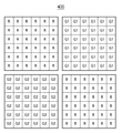
図6は、パラメータ決定部107内の構成の一例を示したブロック図である。以下に、ステップS705で行なわれるパラメータ決定部107の動きを、図6を用いて説明する。図6中の画像データ読み取り部601は、撮像装置の記録媒体に格納されているソース画像データ501とディスティネーション画像データ502を読み出す。色変換リスト作成部602は、読み出されたソース画像データ501とディスティネーション画像データ502における同位置の画素のRGB信号値の差に基づき、図7Aのようなソース画像のRGB信号値からディスティネーション画像のRGB信号値への色変換リスト700を作成する。
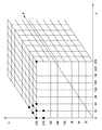
【0032】
この色変換リスト700は、RGB空間に図7Bの如く設定した各格子点のRGB信号値が、ソース画像からディスティネーション画像への色変換においてどのように変化するかを示したものである。本実施形態では、RGBの各軸について信号値0〜255(8ビット)を32ステップ刻みで8分割し、RGB空間に9×9×9=729個の格子点を設定している。色変換リスト700のソース画像側のRGB信号値は各格子点のRGB信号値であり、ディスティネーション側のRGB信号値はそれぞれの変換結果に対応する。図8AのステップS705において行なわれるリスト700の作成処理を図8Bのフローチャートにより詳述するが、格子点近傍のRGB信号値を有するソース画像中の画素とこれに対応するディスティネーション画像中の画素のRGB値を用いることによりリスト700が作成される。
【0033】
パラメータ作成部603は、色変換リスト700に記録されたRGB値の変化を実現するように上記パラメータを決定する。
【0034】
以下、リスト作成の手順を図8Bのフローチャートに従って説明する。
【0035】
図8において、まず初めに基準信号値が発生される。この基準信号値は各格子点のRGB信号値であり、Rsn信号(n=0〜728)、Gsn信号(n=0〜728)、及びBsn信号(n=0〜728)を発生する(ステップS801)。なお、格子点の設定は上記(図7B)に限定されないことはいうまでもない。
【0036】
次に、発生した基準信号値(Rsn,Gsn,Bsn)に近いRGB信号値をソース画像信号中からサーチし、そのRGB信号値と画素位置を保持する(ステップS802)。このサーチでは、例えば以下の式(11)より求まる信号値差Eが所定の閾値Thよりも小さくなるRGB信号値を有する画素を抽出し、そのRGB信号値と画素位置を保持する。
【0037】
【数4】
ただし、式(11)において、x、yは画像座標値を示し、A(x,y)はx、y座標値におけるA信号の値を示す。またここで、信号値差Eは、色空間上における基準信号値(Rsn,Gsn,Bsn)とソース画像中のRGB信号値(Rs,Gs,Bs)との距離を表している。
【0039】
ステップS803では、ステップS802で保持された画素がN個以上存在しているか否かを判定する。この判定の結果、ステップS802によってN個以上の画素が保持されていれば、ステップS805へ、そうでなければステップS804へ進む。
【0040】
ステップS805では、当該基準信号に対応する信号値を以下の手順で算出する。まず、以下の式(12)〜式(14)を用いて、ディスティネーション画像中の対応する画素のRGB信号値との差分信号値をdR、dG、dBを求める。即ち、ステップS802でサーチされ保持された各画素とディスティネーション画像中の対応する画素とのRGB信号値の差を、
dR=Rs(x,y)-Rd(x,y) …式(12)
dG=Gs(x,y)-Gd(x,y) …式(13)
dB=Bs(x,y)-Bd(x,y) …式(14)
により求める。
【0041】
そして、ステップS802で保持された全画素についてのdR、dG、dBの平均値(dRの平均値dRave、dGの平均値dGave、及びdBの平均値dBave)を算出し、これら平均値と式(15)〜(17)を用いてソース画像における各格子点位置のRGB信号値がディスティネーション画像においてどのように変化するかを求める。
Rdn=Rsn-dRave …式(15)
Gdn=Gsn-dGave …式(16)
Bdn=Bsn-dBave …式(17)。
【0042】
一方、信号値差Eの値がスレッショルド値Thより小さい画素がソース画像中にN個以上存在しない場合はノイズとみなし、基準信号値(Rsn,Gsn,Bsn)をそのままディスティネーション画像における格子点位置のRGB信号値(Rdn,Gdn,Bdn)とする。
Rdn=Rsn …式(18)
Gdn=Gsn …式(19)
Bdn=Bsn …式(20)。
【0043】
パラメータ作成部603は、以上のようにして求められた色変換リストに記録されている色変換が実現されるようにパラメータを決定する。まず、変換リスト中のソース画像側のRGB信号値(基準信号値(Rsn信号、Gsn信号、及びBsn信号)に相当する)について、式(10)〜式(1)の逆変換を行う。この逆変換では、変更したい撮影モードのパラメータを用いる。この逆変換の結果をRn、Gn、Bnとする。そして、これらRn、Gn、及びBnの値を変更されたパラメータを用いて式(1)〜式(10)により変換した結果(信号の値)をそれぞれRdn'、Gdn'、及びBdn'とすると、当該撮影モードの新たなパラメータは、次式で求められる値Diffが最小になるように減衰最小自乗法を用いて決定される。
【0044】
【数5】
パラメータ作成部603は,以上のようにして、ソース画像及びディスティネーション画像の関係から新たに求めたパラメータを、パラメータを変更すべく指定された撮影モードのパラメータとして撮像装置内部あるいは撮像装置外部の着脱可能な記録媒体(不図示)に記憶する。
【0046】
次に、パラメータ変更が行われた撮影モードでの撮影データの流れを図1、および図2を用いて説明する。前述のようにソース画像をレタッチすることによってパラメータ変更を行った撮影モードが選択され、撮影が行われると、撮像部101からA/D変換部103により、撮影されたCCD信号が画像処理部104へと送られる。画像処理部104では図2のホワイトバランス処理部201からエッジ合成処理部208までの処理が行われるが、そこで用いられるパラメータは予め用意されたパラメータではなく、撮像装置内部あるいは撮像装置外部の着脱可能な記録媒体に記憶されている変更されたパラメータが読み出されて処理が行われる。
【0047】
変更されたパラメータにより処理された画像データはフォーマット変換部105へと送られ、画像フォーマットにしたがって変換され、画像記録部106にて撮像装置の記録媒体へと書き込まれる。以上がパラメータ変更が行われた撮影モードでのデータの流れである。
【0048】
以上のように、本実施形態によれば、ソース画像とディスティネーション画像の関係から新たに求められたパラメータをパラメータ変更された撮影モードとして記録媒体に保持しておくことができる。そして、このパラメータ変更された撮影モードを選択することにより、以降の撮影では変更されたパラメータが適用されて自動的に画像処理されることとなる。そのため、ユーザの好みの色味を撮影時に反映させることが可能になり、一度のパラメータ設定によって統一された色味の撮影画像を自動的に得ることができる。また、その際に撮像時にどのようなパラメータ、色変換リストやLUTを用いて処理されたか特定できる情報を画像とともにタグ情報の中に記録しておいてもよい。
【0049】
また、上記実施形態では、予め決められた撮影モードのパラメータを変更し、変更後のパラメータによって当該撮影モードのパラメータを上書きする場合について述べたがこれに限られるものではない。例えば、ユーザが予めカスタム設定可能な撮影モード(カスタムモード)を1つ又は複数用意しておき、作成されたパラメータをそのカスタムモードのパラメータとして保持するようにしても良い。このようにすれば、予め用意された撮影モードのパラメータを維持させることができる。
【0050】
以上のように、第1実施形態では、任意のソース画像データと、このソース画像データがレタッチされることにより得られるディスティネーション画像データとを記録しておき、所望の撮影モードについて画像再生パラメータの変更を実行することがユーザにより指定されると、ソース画像データとディスティネーション画像データとを比較して色変換リストを作成し、作成した色変換リストを用いて当該撮影モードにおける画像再生パラメータを変更する。このため、ユーザの好みの色設定を再生する画像に対して容易に与えることができる。また、画像全体ではなく、一部の色のみをユーザの好みの色へと変換することも容易に実現することができる。
【0051】
なお、第1実施形態においては、画像再生パラメータを書き換える撮影モードを1つ指定して、その撮影モードのみのパラメータを書き換えて登録する例をあげたが、1つのモードだけではなく、ユーザが指定した複数の撮影モードを同時に書き換える様にしてもよい。この場合、式(10)〜式(1)の逆変換を指定された各撮影モードに設定されている画像再生パラメータを用いて実行することになる。即ち、1つの色変換リストを用いて、上述のパラメータ作成部603による処理を指定された撮影モードの各々について実行させることになる。
【0052】
また、第1実施形態においては、ソース画像とディスティネーション画像のフォーマットにBMPファイルフォーマットを用いたが、ソース画像とディスティネーション画像のフォーマットはこれに限られるものではなく、JPEGや、TIFF等のファイルフォーマットを用いて行うことも可能である。
【0053】
さらに、第1実施形態では、撮像装置が上述したパラメータ決定処理を含む画像処理を実行するように構成しているので、撮像処理に伴って前述した色変換処理を行える。しかしながら、必ずしも撮像装置が上記画像処理を実行するように構成する必要はない。例えば、上記画像処理を実行する画像処理装置を単独で構成してもよい。このように構成すれば、ユーザが所有する任意の画像データを入力して前述した色変換処理を行うことができ、ユーザの好みの色設定を容易に行える。
【0054】
この場合、例えば、ソース画像とディスティネーション画像、またはそれらに代る色変換リストを用いて画像変換パラメータを決定し、決定されたパラメータでもって、例えば撮像装置に予め用意されている画像再生パラメータを変更する。そして、作成された色変換リストあるいは変更された画像変換パラメータに名前を付けて登録する登録作業を行う。登録作業は画像再生パラメータの変更を行うべき撮影モードを指定し、パラメータ変更の実行することによって登録されるようにしてもよい。或いは、当該画像処理装置によって、登録された画像変換パラメータを用いてユーザが所有する任意の画像データを色変換することもできる。なお、上記において、画像変換パラメータは、前述した画像再生パラメータに相当するパラメータである。上記画像処理装置は撮像装置と別体であってもよく、別体の場合は、例えばUSB等のインターフェースを介して生成した画像再生パラメータを撮像装置に転送するように構成することになる。
【0055】
<第2実施形態>
次に、本発明の第2実施形態を説明する。第1実施形態では、生成した色変換リストに基づいて式(1)、(3)、(9)の画像再生パラメータを変更したが、第2実施形態では、図9の3次元ルックアップテーブル演算処理部909におけるルックアップテーブルの値(格子点データ)を変更する。図9は、第2実施形態による画像処理部104に含まれる処理を説明するためのブロック図である。以下に図9のブロック図を用いて本実施形態の撮像装置における画像処理の流れを説明する。
【0056】
ホワイトバランス処理部901、補間処理部902、マトリクス演算部903、色差ゲイン演算部904、ガンマ処理部905、色相補正演算処理部906、エッジ強調処理部907、及びエッジ合成処理部908の動きは、前述した第1の実施形態と同じである為、ここでは詳細な説明をしない。ここでは、第1の実施形態にはなかった3次元ルックアップテーブル演算処理部909について詳細に説明する。
【0057】
色相補正演算処理部906により処理されたCCDデジタル信号(入力RGB信号)Rh、Gh、Bhは、3次元ルックアップテーブル演算処理部909へと送られ、CCDデジタル信号(出力RGB信号)RL、GL、BLへと変換される。
【0058】
以下に、3次元ルックアップテーブル演算について簡単に説明する。なお、ここではRGBの3次元ルックアップテーブルを用いて説明しているが、ルックアップテーブルは、扱う信号に応じて多次元ルックアップテーブルとしても構わない。
【0059】
本実施形態においては、3次元ルックアップテーブルの容量を減らすため、R信号、G信号、及びB信号の最小値から最大値までを9分割した、9×9×9の729の3次元代表格子点(ルックアップテーブル)を用意し、代表格子点以外のRGB信号は補間により求める。
【0060】
また補間演算は以下の式(22)〜式(24)により行われる。ただし、式(22)〜式(24)において、入力RGB信号をR、G、B、そのときの出力RGB信号をRout(R,G,B)、Gout(R,G,B)、Bout(R,G,B)とする。また、入力RGB信号R、G、Bそれぞれの信号値より小さく、かつ一番近い値の代表格子点の信号をRi、Gi、Biとする。さらに、代表格子点出力信号をRout(Ri,Gi,Bi)、Gout(Ri,Gi,Bi)、Bout(Ri,Gi,Bi)とし、代表格子点のステップ幅をStep(本実施形態においては32)とする。
【0061】
以下、上記式(22)、式(23)、及び式(24)のルックアップテーブル変換及び補間演算式を簡易的に以下のような式(25)で表すことにする。ただし、式(25)において、R、G、Bは入力信号値を示し、LUTは9×9×9のルックアップテーブルを示し、Rout、Gout、Boutはルックアップテーブル変換及び補間演算した結果を示す。
(Rout,Gout,Bout)=LUT[(R,G,B)] …式(25)。
【0063】
以上のような演算を用いて、入力RGB信号Rh、Gh、Bhを出力RGB信号RL、GL、BLに変換する(式(26))。
(RL,GL,BL)=LUT[(Rh,Gh,Bh)] …式(26)。
【0064】
3次元ルックアップテーブル変換及び補間演算された信号は、エッジ合成処理部908へと送られる。エッジ合成処理部908では、3次元ルックアップテーブル演算処理部909から送られてきた出力RGB信号(RL、GL、BL信号)にエッジ強調処理部907で検出されたエッジ信号が加えられる。以上が第2実施形態による画像処理演算の流れである。
【0065】
ユーザがパラメータの変更を行わない場合は、式(1)中のM11,M21,M31,…,M33、式(3)中のG1,G2、式(9)中のH11,H21,H12,H22、及び式(26)のルックアップテーブルLUTの各値として、撮影モードに対応して予め設定されている画像再生パラメータのデフォルト値が用いられる。
【0066】
そして、第2実施形態においては、ユーザがパラメータの変更を行う場合には、式(26)のルックアップテーブルの格子点データが決定され、ルックアップテーブルの格子点データのみが置換されることになる。以下にパラメータの変更動作を説明する。色変換リスト700が作成されると、色変換リスト700を元にルックアップテーブルの格子点データを決定する。なお、本実施形態におけるパラメータの変更において、色変換リスト700の作成までは第1実施形態と同様であるため、ここでは詳細な説明を省略する。色変換リスト700が作成されると、色変換リスト700を元に、3次元ルックアップテーブルの格子点データを決定する。なお、3次元ルックアップテーブルの格子点データの決定は、あらかじめ撮像装置内に設定されているデフォルトのルックアップテーブルと色変換リスト700を用いて決定される。
【0067】
まず、初めに色変換リストを元にソース画像信号からディスティネーション画像信号に変換する3次元ルックアップテーブルLUTlistを作成する。この色変換リストの3次元ルックアップテーブル変換及び補間演算処理は以下の式(27)に示すような変換式を用いて行われる。
(Rdn,Gdn,Bdn)=LUTlist[(Rsn,Gsn,Bsn)] …式(27)。
【0068】
色変換リストに基づく色変換を撮像装置の3次元ルックアップテーブル変換に反映すると以下の式(28)ような式で表される。
(RL',GL',BL')=LUTlist[LUT[(Rh,Gh,Bh)]] …式(28)。
【0069】
また、デフォルトのルックアップテーブル及び色変換リストに基づくルックアップテーブルは、一つのルックアップテーブルにマージすることが可能なため、式(28)は、以下の式(29)のような一つのルックアップテーブルとすることができる。
(RL',GL',BL')=LUTcustm[(Rh,Gh,Bh)] …式(29)。
【0070】
以上のように、2つのルックアップテーブル(LUT、LUTlist)をマージして求められた新しいルックアップテーブルLUTcustmをユーザの設定した撮像装置のパラメータ変更を行いたい撮影モードの3次元ルックアップテーブルとして置き換える。
【0071】
以上のように、第2実施形態では、任意のソース画像データと、ソース画像データがレタッチされることにより得られるディスティネーション画像データとを記録しておき、パラメータの変更を行う撮影モードが設定され、パラメータの変更を実行することがユーザにより指定されると、ソース画像データとディスティネーション画像データとを比較して色変換リストを作成するとともに、作成した色変換リストに基づいて3次元ルックアップテーブルの格子点データを決定し、決定した3次元ルックアップテーブルの格子点データを設定された撮影モードにおける3次元ルックアップテーブルの格子点データとするようにしたので、ユーザの好みの色設定を、再生する画像に対して容易に与えることができる。また、色を変更したいルックアップテーブルの格子点についてのみ変更されるので、画像全体ではなく、一部の色のみをユーザの好みの色へと変換することもより容易に実現することができる。
【0072】
すなわち、前述した第1の実施形態のように、マトリクス演算、色差ゲイン演算、ガンマ処理、色相補正演算処理等のパラメータを用いて、カスタマイズしようとした場合、ユーザがある特定の色のみを変更しようとしても、その色だけを変更することは不可能である。しかしながら、本実施形態のように3次元ルックアップテーブルを用いることにより、他の色(他の色領域)はまったく変更せずに、特定の色(特定の色領域)だけを変更することが可能になる。
【0073】
なお、本実施形態においては、第1の実施形態と同様にソース画像とディスティネーション画像とを撮像装置の記録媒体に記録して、撮像装置内で色変換リストを作成し、それに基づきパラメータを決定する例を示したが、あらかじめ色変換リストをパソコンで作成し、色変換リストを記録媒体に直接記録して、その色変換リストを元にパラメータを決定するようにしてもよい。
【0074】
<第3実施形態>
第1実施形態では、レタッチ処理の前後の画像の対応する画素のRGB信号値を用いて色変換リスト700を作成した。第3実施形態では、ユーザが指定する画素のペアのRGB信号値を用いて色変換リストを作成する。なお、第3実施形態で作成した色変換リストに基づき、第1実施形態で説明した画像再生パラメータの変更や第2実施形態で説明したルックアップテーブルの作成あるいは更新ができることは明らかである。
【0075】
以下に第3実施形態による色変換リストの作成処理を説明する。
【0076】
図10に示される画像は変換元の第1の色を指示するために用意されたソース画像1001、その第1の色の変換目標色である第2の色を指定するために用意されたディスティネーション画像1002である。ユーザはこれら2つの画像を用意するが、これら2つの画像は本実施形態の撮像装置とは異なる撮像装置で撮影した画像であってもよいし、ユーザがレタッチ処理して作成した画像であってもかまわない。また、ソース画像とディスティネーション画像は本撮像装置が対応しているフォーマットであれば、JPEG、TIFF、GIF等どのようなフォーマットでもよい。また、ソース画像とディスティネーション画像の大きさはそれぞれ異なっていてもよい。また、ソース画像とディスティネーション画像は撮像時に得られる撮影画像データを用いてもよいし、当該撮影画像データとともに記録媒体に記録されるサムネイル画像データを用いてもよい。撮影画像データは、撮像素子からの出力信号をA/D変換し、非圧縮あるいは、可逆圧縮をして所定のフォーマットに変換されたRAWデータでも良い。
【0077】
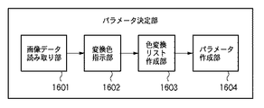
ユーザは上記2つの画像を撮像装置の記録メディア内に記録し、パラメータ決定を開始する。パラメータの決定は図1のパラメータ決定部107により行われる。図11は第3実施形態によるパラメータ決定部107の機能構成を示すブロック図である。以下に、第3実施形態によるパラメータ決定部107の動作を図11を用いて説明する。
【0078】
まず、画像データ読み取り部1601では撮像装置の記録媒体に格納されているソース画像とディスティネーション画像を読み出す。読み出された画像データは、図示は省略するが、撮像装置の画像表示部に表示される。ユーザは画像表示部に表示されたソース画像中にある変換元となるソース色を図10中に示すようなカーソルAを移動することにより指定する。同様に、ディスティネーション画像中から当該ソース色の変換目標となるディスティネーション色をカーソルBを移動して指定する。変換したいソース色が複数存在する場合には続けてソース画像中の次のソース色とその変換目標となるディスティネーション画像中のディスティネーション色を指定していく。この色指定作業により図12のような変換色指示リストが生成される。変換色指示リストには、ソース色のRGB信号値(Rs(i),Gs(i),Bs(i))と、それぞれについて変換目標として指示されたディスティネーション色のRGB信号値(Rd(i),Gd(i),Bd(i))のペアが登録される。なお、ユーザが設定した変換したい色の数(色のペア数)をCとすると、i=0〜C−1となる。
【0079】
以上のようにして色変換指示リストが作成されると、色変換指示リストは色変換リスト作成部603へと送られる。色変換リスト作成部603は、色変換指示リストに基づいて第1実施形態で説明したような色変換リスト700を生成する。パラメータ作成部1604は、生成された色変換リスト700の内容に基づいて、第1及び第2実施形態で説明した方法で画像再生パラメータ(M11,M21,M31,…,M33、G1,G2、H11,H21,H12,H22、或いはルックアップテーブル)を更新する。
【0080】
次に色変換リストからパラメータ作成を行う手順を図13のフローチャートを参照して説明する。
【0081】
まずステップS1801において、基準信号Rsn、Gsn、Bsnを発生する。この基準信号は図7Bを参照して第1実施形態で説明した基準信号値と同じものである。次に、ステップS1802において、ステップS1801で発生した基準信号値に近いRGB信号値を上記色変換指示リストよりサーチする。このサーチは、i=0〜C−1の各ソース色について、以下に示す式(30)を用いて信号値差Eを算出し、この信号値差Eが閾値Thよりも小さくなるRGB信号値を抽出するものである。
【0082】
【数6】
ステップS1802で1つ以上のRGB信号値が抽出されたならば、ステップS1805へ進み、変換後の当該基準信号に対応する色信号値を算出する。まず、抽出されたソース色のRGB信号値と、そのソース色の対として色変換指示リストに記録されているディスティネーション色のRGB信号値の差分信号dR、dG、dBを求める。
dR = Rs(i)-Rd(i) …式(31)
dG = Gs(i)-Gd(i) …式(32)
dB = Bs(i)-Bd(i) …式(33)
但し、(Rs(i)、Gs(i)、Bs(i))は抽出されたソース色のRGB信号値であり、(Rd(i)、Gd(i)、Bd(i))は夫々のソース色に対応するディスティネーション色のRGB信号値である。
【0084】
そして、抽出された信号におけるdRの平均値dRave、dGの平均値dGave、dBの平均値dBaveを求め、基準信号Rsn、Gsn、Bsnとの演算により、Rsn、Gsn、Bsnに対応する色変換後の信号値Rdn、Gdn、Bdnが求められる。
Rdn =Rsn- dRave …式(34)
Gdn =Gsn- dGave …式(35)
Bdn =Bsn- dBave …式(36)
【0085】
また、信号値差Eの値が閾値Thより小さいものが一つも存在しない場合は、ステップS1803からステップS1804へ進み、以下の式によりRdn、Gdn、Bdnが求められる。
Rdn = Rsn …式(37)
Gdn = Gsn …式(38)
Bdn = Bsn …式(39)。
【0086】
以上の処理をn=0〜728まで実行することにより、色変換リストが生成される。そして、こうして求められた色変換リストに基づき、画像再生パラメータ或いは3次元ルックアップテーブルが作成される。作成されたルックアップテーブルによって予め設定されているルックアップテーブルを上書きして更新するようにしてもよい。
【0087】
なお、上記第3実施形態では、色変換リストを作成するにあたり、ソースとディスティネーションの2つの画像を用いたが、図14に示すように同一画像中からソース色とディスティネーション色の組み合わせを指定するようにしてもかまわない。更に、3つ以上の画像の中からソース色とディスティネーション色のペアを指定するようにしてもよい。また本実施形態における3次元ルックアップテーブルのパラメータは信号値32ステップ刻みの729の格子点をもつものであったが、これに限られるものではなく、どのような格子点間隔のものであってもよい。
【0088】
以上のように第3実施形態によれば、ユーザの好みの色再現を設定するにあたり、変換元の色であるソース色と変換後の目標色であるディスティネーション色を画像でユーザに指示させることにより、容易にユーザの好みの撮像装置の色設定を実現することが可能となる。また、3次元ルックアップテーブルを用いた色変換を行うことにより画面全体に影響を及ぼすパラメータではなく、一部の色のみを好みの色へと変換することも容易に実現することが可能となる。
【0089】
以上の第1乃至第3実施形態では、RGB信号によって表されるソース画像、ディスティネーション画像について述べたが、RGB信号に限らず、CMYG信号等であってもよい。CMYGを用いた場合は、4次元ルックアップテーブルを用いるように可変に設定できる。他にYCrCbやL*a*b信号等を用いても構わない。
【0090】
<第4実施形態>
上記第1乃至第3実施形態においてソース画像とディスティネーション画像をもとに作成された画像再生パラメータ、あるいはパラメータにより作成された色変換リスト、あるいはルックアップテーブルを撮影装置の内部メモリや着脱可能な記録メディアに記録することができる。なお、記録する際に、複数の色変換リスト等が記録されることもあるため、それぞれ名前を付けて登録するのが好ましい。また、各々異なる色変換リスト、画像変換パラメータ、あるいはルックアップテーブルを登録できる複数のカスタムモードを有する場合や、カスタムモードが複数の異なる色変換リスト、画像変換パラメータ、もしくはルックアップテーブルを登録できる場合には、登録されているものを撮像装置の表示部に図15のように一覧表示する。
【0091】
ユーザが撮影時に撮影モードを選択するとともに更新された複数の色変換リスト等が登録されている一覧表示し、その中からユーザが好ましいものを選択する。また、撮影時に限らず、撮影後であっても、着脱可能な記録メディアに入っている変換対象とする撮影画像を選択して、登録されている色変換リスト等を選択すれば、選択された撮影画像に対して色変換が行われるようにしてもよい。
【0092】
<他の実施形態>
前述した実施形態の機能を実現するべく各種のデバイスを動作させるように、該各種デバイスと接続された装置あるいはシステム内のコンピュータに対し、前記実施形態の機能を実現するためのソフトウェアのプログラムコードを供給し、そのシステムあるいは装置のコンピュータ(CPUあるいはMPU)に格納されたプログラムに従って前記各種デバイスを動作させることによって実施したものも、本発明の範疇に含まれる。
【0093】
また、この場合、前記ソフトウェアのプログラムコード自体が前述した実施形態の機能を実現することになり、そのプログラムコード自体、及びそのプログラムコードをコンピュータに供給するための手段、例えば、かかるプログラムコードを格納した記録媒体は本発明を構成する。かかるプログラムコードを記憶する記録媒体としては、例えばフレキシブルディスク、ハードディスク、光ディスク、光磁気ディスク、CD−ROM、磁気テープ、不揮発性のメモリカード、ROM等を用いることができる。
【0094】
また、コンピュータが供給されたプログラムコードを実行することにより、前述の実施形態の機能が実現されるだけでなく、そのプログラムコードがコンピュータにおいて稼働しているOS(オペレーティングシステム)あるいは他のアプリケーションソフト等と共同して前述の実施形態の機能が実現される場合にもかかるプログラムコードは本発明の実施形態に含まれることは言うまでもない。
【0095】
さらに、供給されたプログラムコードがコンピュータの機能拡張ボードやコンピュータに接続された機能拡張ユニットに備わるメモリに格納された後、そのプログラムコードの指示に基づいてその機能拡張ボードや機能拡張ユニットに備わるCPU等が実際の処理の一部または全部を行い、その処理によって前述した実施形態の機能が実現される場合にも本発明に含まれることは言うまでもない。
【0096】
【発明の効果】
以上説明したように本発明によれば、ソース画像から指定された変換元の画素値とディスティネーション画像から指定された変換目標の画素値からなる画素値のペアに基づいて第1の色を第2の色に変換するための画像処理パラメータを新たに生成し、生成された画像処理パラメータを更新することによって、撮影により得られる撮像画像を処理するための撮影モードとして登録しておくので、撮影者が撮影時に撮影モードを設定するだけで自動的に撮影者の色変換の好みを反映した画像処理パラメータを適用して変換された画像を撮影画像として得ることが可能になる。
【図面の簡単な説明】
【図1】 第1実施形態による撮像装置の構成の一例を示したブロック図である。
【図2】 第1実施形態による画像処理部の処理を説明するブロック図である。
【図3】 第1実施形態によるA/D変換後のCCDデジタル信号の概念を示す概念図である。
【図4】 第1実施形態による補間処理後のCCDデジタル信号の概念を示す概念図である。
【図5】 第1実施形態によるソース画像とディスティネーション画像とを示す図である。
【図6】 第1実施形態によるパラメータ決定部の処理を説明するブロック図である。
【図7A】 第1実施形態による色変換リストを示す図である。
【図7B】 第1実施形態による基準信号を説明する図である。
【図8A】 ソース画像とディスティネーション画像を用いた一連の処理を示すフローチャートである。
【図8B】 第1実施形態による色変換リストの作成処理を説明するフローチャートである。
【図9】 第2実施形態による画像処理部の処理を説明するブロック図である。
【図10】 第3実施形態によるソース色とディスティネーション色を指定する方法を説明する図である。
【図11】 第3実施形態によるパラメータ決定部の処理を説明するブロック図である。
【図12】 第3実施形態による色変換指示リストの一例を示す図である。
【図13】 第3実施形態による色変換リストの作成処理を説明するフローチャートである。
【図14】 第3実施形態によるソース色とディスティネーション色の指定方法の他の例を説明する図である。
【図15】 第1乃至第3実施形態によって作成され、登録された画像再生パラメータあるいは色変換リストの一覧表示例を示す図である。[0001]
BACKGROUND OF THE INVENTION
The present invention Imaging apparatus, imaging method, control program, and computer-readable memory In particular, it is suitable for use in performing color conversion processing on image data obtained by imaging a subject.
[0002]
[Prior art]
Some conventional imaging devices allow color conversion parameters (hue, saturation, gamma table, contrast, etc.) to be changed in the imaging device so that an image preferred by the user can be obtained. In general, in such an imaging apparatus, a user can select a desired parameter from a plurality of parameters prepared in advance by a manufacturer, and color conversion processing is executed using the selected parameter. Thus, the user's favorite image can be obtained (see Patent Document 1).
[0003]
[Patent Document 1]
JP 11-187351 A
[0004]
[Problems to be solved by the invention]
However, in such a conventional imaging device, when setting the color conversion parameter, it is necessary to actually change the color conversion parameter and shoot a similar scene to check whether a desired image can be obtained. There wasn't. In other words, setting the color conversion parameter is very time-consuming because it requires such a trial and error procedure.
[0005]
In addition, the change of the color conversion parameter in such a conventional imaging apparatus changes only a specific color (for example, a sky color) in order to affect the problem that the degree of freedom of the change is small and all reproduced colors. There is a problem that it is not possible to answer such needs. For this reason, the setting as desired by the user is not always possible, and there is a problem that it is difficult to easily obtain an image that the user likes.
[0006]
The present invention has been made in view of the above-described problems, and an object thereof is to easily obtain a user's favorite image.
Another object of the present invention is to automatically set color conversion parameters based on images before and after editing by retouching and the like, and to easily realize user's favorite color conversion.
Another object of the present invention is to automatically set color conversion parameters from a color pair designated by the user, and to easily realize user's favorite color conversion. is there.
Another object of the present invention is to make it possible to change only a desired color and a color close thereto.
[0007]
[Means for Solving the Problems]
In order to achieve the above object, an image processing apparatus according to the present invention comprises the following arrangement. That is,
Imaging obtained from an imaging unit having an imaging device An input means for inputting an image;
Designation means for designating a pixel value from each of a source image for designating a first color of a conversion source and a destination image for designating a second color of a conversion target corresponding to the first color;
Obtaining means for obtaining one or more pairs of pixel values composed of a conversion source pixel value designated from the source image and a conversion target pixel value designated from the destination image by the designation means;
An image processing parameter for converting the first color into the second color based on a pair of pixel values acquired by the acquisition unit. Newly generated, A decision means to decide;
Determined by the determining means Said Image processing parameters In order to process the image obtained by shooting Shooting mode By updating the image processing parameters to the shooting mode Registration means to register as,
When shooting Said A shooting mode setting means for setting a shooting mode;
By the shooting mode setting means Set The shooting mode Automatically according to Image processing parameters registered by the registration means Apply Input by the input means Imaging Convert the pixel value of the image and convert the converted image Imaging Conversion means for outputting as an image.
[0011]
DETAILED DESCRIPTION OF THE INVENTION
Hereinafter, preferred embodiments of the present invention will be described with reference to the accompanying drawings.
[0012]
<First Embodiment>
FIG. 1 is a block diagram illustrating an example of a configuration of an imaging apparatus to which the image processing apparatus of the present embodiment is applied. In FIG. 1, an
[0013]
The CCD digital signal obtained by the A /
[0014]
The shooting
[0015]
Here, the shooting mode is to set image reproduction parameters according to the imaging conditions in each scene, such as landscape mode, portrait mode, night view mode, and the gamma table, matrix calculation coefficient, Lookup table data is different. For example, in the portrait mode, the saturation is lowered, in the landscape mode, the saturation is increased to increase the contrast, and in the night view mode, black is set as a parameter of the sun setting. Further, a customization mode in which the user can arbitrarily register at least one parameter may be prepared.
[0016]
The operation of the
[0017]
The CCD digital signal output from the A /
[0018]
In the
[0019]
[Expression 1]
The CCD digital signal that has been subjected to matrix calculation processing in the
[0021]
[Expression 2]
The CCD digital signal that has been subjected to the above-described color difference gain calculation processing by the color difference gain
Rt = GammaTable [Rg] ... Formula (5)
Gt = GammaTable [Gg] ... Formula (6)
Bt = GammaTable [Bg] (7)
[0023]
The gamma-processed CCD digital signal is sent to the hue correction
[0024]
[Equation 3]
On the other hand, the edge
[0026]
When the user does not change the parameters, the parameters set by the shooting
[0027]
The
[0028]
A series of processing using the source image and the destination image will be briefly described with reference to the flowchart of FIG. 8A.
[0029]
The user reads out from the internal memory of the imaging apparatus or a removable recording medium outside the imaging apparatus (step S701) and retouchs while viewing the
[0030]
When the parameter change is instructed by the user, the
[0031]
FIG. 6 is a block diagram showing an example of the configuration in the
[0032]
This
[0033]
The
[0034]
The list creation procedure will be described below with reference to the flowchart of FIG. 8B.
[0035]
In FIG. 8, first, a reference signal value is generated. This reference signal value is an RGB signal value at each grid point, and generates an Rsn signal (n = 0 to 728), a Gsn signal (n = 0 to 728), and a Bsn signal (n = 0 to 728) (step). S801). Needless to say, the setting of the grid points is not limited to the above (FIG. 7B).
[0036]
Next, an RGB signal value close to the generated reference signal value (Rsn, Gsn, Bsn) is searched from the source image signal, and the RGB signal value and the pixel position are held (step S802). In this search, for example, a pixel having an RGB signal value whose signal value difference E obtained from the following equation (11) is smaller than a predetermined threshold Th is extracted, and the RGB signal value and the pixel position are held.
[0037]
[Expression 4]
In equation (11), x and y indicate image coordinate values, and A (x, y) indicates the value of the A signal in the x and y coordinate values. Here, the signal value difference E represents the distance between the reference signal value (Rsn, Gsn, Bsn) in the color space and the RGB signal value (Rs, Gs, Bs) in the source image.
[0039]
In step S803, it is determined whether there are N or more pixels held in step S802. As a result of the determination, if N or more pixels are held in step S802, the process proceeds to step S805, and if not, the process proceeds to step S804.
[0040]
In step S805, a signal value corresponding to the reference signal is calculated according to the following procedure. First, using the following formulas (12) to (14), dR, dG, and dB are obtained as differential signal values from the RGB signal values of the corresponding pixels in the destination image. That is, the RGB signal value difference between each pixel searched and held in step S802 and the corresponding pixel in the destination image is
dR = Rs (x, y) -Rd (x, y) (12)
dG = Gs (x, y) -Gd (x, y) (13)
dB = Bs (x, y) -Bd (x, y) (14)
Ask for.
[0041]
Then, average values of dR, dG, and dB (average value of dR, dRave, average value of dG, dGave, and average value of dB dBave) for all the pixels held in step S802 are calculated. 15) to (17) are used to determine how the RGB signal value at each grid point position in the source image changes in the destination image.
Rdn = Rsn-dRave ... Formula (15)
Gdn = Gsn-dGave (16)
Bdn = Bsn-dBave (Expression (17))
[0042]
On the other hand, if N or more pixels whose signal value difference E is smaller than the threshold value Th are not present in the source image, it is regarded as noise, and the reference signal values (Rsn, Gsn, Bsn) are used as they are in the destination image. RGB signal values (Rdn, Gdn, Bdn).
Rdn = Rsn (18)
Gdn = Gsn (19)
Bdn = Bsn Expression (20).
[0043]
The
[0044]
[Equation 5]
The
[0046]
Next, the flow of shooting data in the shooting mode in which the parameters are changed will be described with reference to FIG. 1 and FIG. As described above, when the shooting mode in which the parameter is changed is selected by retouching the source image and shooting is performed, the captured CCD signal is captured by the A /
[0047]
The image data processed with the changed parameters is sent to the
[0048]
As described above, according to the present embodiment, a parameter newly obtained from the relationship between the source image and the destination image can be held in the recording medium as the imaging mode with the parameter changed. Then, by selecting the imaging mode with the parameter changed, the changed parameter is applied and image processing is automatically performed in subsequent imaging. Therefore, the user's favorite color can be reflected at the time of shooting, and a shot image with a unified color can be automatically obtained by a single parameter setting. Further, at this time, information that can specify what parameters, color conversion list, and LUT were used at the time of imaging may be recorded in the tag information together with the image.
[0049]
In the above embodiment, a case has been described in which a predetermined shooting mode parameter is changed and the shooting mode parameter is overwritten by the changed parameter. However, the present invention is not limited to this. For example, one or a plurality of shooting modes (custom modes) that can be custom-set by the user may be prepared in advance, and the created parameters may be held as parameters for the custom mode. In this way, it is possible to maintain shooting mode parameters prepared in advance.
[0050]
As described above, in the first embodiment, arbitrary source image data and destination image data obtained by retouching the source image data are recorded, and image reproduction parameters for a desired shooting mode are recorded. When execution of the change is specified by the user, a color conversion list is created by comparing the source image data and the destination image data, and the image reproduction parameter in the shooting mode is changed using the created color conversion list. To do. For this reason, a user's favorite color setting can be easily given to an image to be reproduced. Also, it is possible to easily convert not only the entire image but only a part of colors into a user's favorite color.
[0051]
In the first embodiment, an example has been given in which one shooting mode for rewriting the image reproduction parameter is specified, and the parameter for only the shooting mode is rewritten and registered. The plurality of shooting modes may be rewritten at the same time. In this case, the inverse transformation of Expression (10) to Expression (1) is executed using the image reproduction parameter set for each designated shooting mode. That is, using the single color conversion list, the above-described processing by the
[0052]
In the first embodiment, the BMP file format is used as the format of the source image and the destination image. However, the format of the source image and the destination image is not limited to this, and a file such as JPEG or TIFF is used. It is also possible to use a format.
[0053]
Furthermore, in the first embodiment, since the imaging device is configured to execute image processing including the parameter determination processing described above, the color conversion processing described above can be performed along with the imaging processing. However, it is not always necessary to configure the imaging apparatus to execute the image processing. For example, an image processing apparatus that executes the image processing may be configured independently. If comprised in this way, the arbitrary color image data which a user owns can be input and the color conversion process mentioned above can be performed, and a user's favorite color setting can be performed easily.
[0054]
In this case, for example, an image conversion parameter is determined using a source image and a destination image, or a color conversion list instead of the source image, and an image reproduction parameter prepared in advance in the imaging apparatus is determined using the determined parameter. change. Then, a registration operation for registering the created color conversion list or the changed image conversion parameter with a name is performed. The registration work may be registered by designating a shooting mode in which the image reproduction parameter should be changed and executing the parameter change. Alternatively, the image processing apparatus can also perform color conversion on arbitrary image data owned by the user using registered image conversion parameters. In the above, the image conversion parameter is a parameter corresponding to the above-described image reproduction parameter. The image processing apparatus may be a separate body from the imaging apparatus. In the case of a separate body, the image reproduction parameter generated via, for example, an interface such as a USB is transferred to the imaging apparatus.
[0055]
Second Embodiment
Next, a second embodiment of the present invention will be described. In the first embodiment, the image reproduction parameters of the expressions (1), (3), and (9) are changed based on the generated color conversion list. In the second embodiment, the three-dimensional lookup table calculation of FIG. The value (grid point data) of the lookup table in the
[0056]
The movements of the white
[0057]
The CCD digital signals (input RGB signals) Rh, Gh, Bh processed by the hue correction
[0058]
Hereinafter, the three-dimensional lookup table calculation will be briefly described. Here, the description is made using an RGB three-dimensional lookup table, but the lookup table may be a multi-dimensional lookup table depending on a signal to be handled.
[0059]
In this embodiment, in order to reduce the capacity of the three-dimensional lookup table, a 9 × 9 × 9 729 three-dimensional representative lattice is obtained by dividing the R signal, the G signal, and the B signal from the minimum value to the maximum value into nine. A point (lookup table) is prepared, and RGB signals other than the representative grid points are obtained by interpolation.
[0060]
The interpolation calculation is performed by the following formulas (22) to (24). However, in the equations (22) to (24), the input RGB signals are R, G, B, and the output RGB signals at that time are Rout (R, G, B), Gout (R, G, B), Bout ( R, G, B). Also, Ri, Gi, and Bi are representative lattice point signals that are smaller than and closest to the input RGB signals R, G, and B, respectively. Further, the representative grid point output signal is Rout (Ri, Gi, Bi), Gout (Ri, Gi, Bi), Bout (Ri, Gi, Bi), and the step width of the representative grid point is Step (in this embodiment) 32).
[0061]
Hereinafter, the look-up table conversion and interpolation calculation formulas of the above formulas (22), (23), and (24) will be simply expressed by the following formula (25). However, in Expression (25), R, G, and B represent input signal values, LUT represents a 9 × 9 × 9 lookup table, and Rout, Gout, and Bout represent the results of lookup table conversion and interpolation. Show.
(Rout, Gout, Bout) = LUT [(R, G, B)] (25)
[0063]
Using the above calculation, the input RGB signals Rh, Gh, Bh are converted into output RGB signals RL, GL, BL (formula (26)).
(RL, GL, BL) = LUT [(Rh, Gh, Bh)] (26).
[0064]
The signal subjected to the three-dimensional lookup table conversion and the interpolation calculation is sent to the edge
[0065]
When the user does not change the parameter, M11, M21, M31,..., M33 in equation (1), G1, G2 in equation (3), H11, H21, H12, H22 in equation (9). As the values of the lookup table LUT in Expression (26), default values of image reproduction parameters set in advance corresponding to the shooting mode are used.
[0066]
In the second embodiment, when the user changes the parameter, the grid point data of the lookup table of Expression (26) is determined, and only the grid point data of the lookup table is replaced. Become. The parameter changing operation will be described below. When the
[0067]
First, a three-dimensional lookup table LUTlist for converting a source image signal to a destination image signal is created based on the color conversion list. The color conversion list three-dimensional lookup table conversion and interpolation calculation processing are performed using a conversion equation as shown in the following equation (27).
(Rdn, Gdn, Bdn) = LUTlist [(Rsn, Gsn, Bsn)] (27).
[0068]
When the color conversion based on the color conversion list is reflected in the three-dimensional lookup table conversion of the imaging apparatus, it is expressed by the following expression (28).
(RL ′, GL ′, BL ′) = LUTlist [LUT [(Rh, Gh, Bh)]] Equation (28).
[0069]
In addition, since the default lookup table and the lookup table based on the color conversion list can be merged into one lookup table, the expression (28) can be converted into one look like the following expression (29). It can be an uptable.
(RL ′, GL ′, BL ′) = LUTcustm [(Rh, Gh, Bh)] Equation (29).
[0070]
As described above, the new look-up table LUTcustm obtained by merging the two look-up tables (LUT, LUTlist) is replaced with a three-dimensional look-up table for the photographing mode in which the user wishes to change the parameters of the image pickup apparatus. .
[0071]
As described above, in the second embodiment, arbitrary source image data and destination image data obtained by retouching the source image data are recorded, and a shooting mode for changing parameters is set. When the user specifies to change the parameters, the source image data and the destination image data are compared to create a color conversion list, and a three-dimensional lookup table based on the generated color conversion list Since the lattice point data of the determined three-dimensional lookup table is set as the lattice point data of the three-dimensional lookup table in the set shooting mode, the user's favorite color setting is It can be easily given to an image to be reproduced. In addition, since only the lattice points of the lookup table whose color is to be changed are changed, it is possible to more easily realize not only the entire image but also converting only a part of the colors to the user's favorite color.
[0072]
That is, as in the first embodiment described above, when trying to customize using parameters such as matrix calculation, color difference gain calculation, gamma processing, hue correction calculation processing, etc., the user should change only a specific color. However, it is impossible to change only that color. However, by using a three-dimensional lookup table as in this embodiment, it is possible to change only a specific color (specific color region) without changing other colors (other color regions) at all. become.
[0073]
In this embodiment, as in the first embodiment, the source image and the destination image are recorded on the recording medium of the imaging device, a color conversion list is created in the imaging device, and parameters are determined based on the color conversion list. However, the color conversion list may be created in advance on a personal computer, the color conversion list may be directly recorded on a recording medium, and the parameters may be determined based on the color conversion list.
[0074]
<Third Embodiment>
In the first embodiment, the
[0075]
The color conversion list creation process according to the third embodiment will be described below.
[0076]
The image shown in FIG. 10 is a
[0077]
The user records the two images in the recording medium of the imaging apparatus, and starts parameter determination. The parameter is determined by the
[0078]
First, the image
[0079]
When the color conversion instruction list is created as described above, the color conversion instruction list is sent to the color conversion
[0080]
Next, the procedure for creating parameters from the color conversion list will be described with reference to the flowchart of FIG.
[0081]
First, in step S1801, reference signals Rsn, Gsn, and Bsn are generated. This reference signal is the same as the reference signal value described in the first embodiment with reference to FIG. 7B. In step S1802, an RGB signal value close to the reference signal value generated in step S1801 is searched from the color conversion instruction list. In this search, a signal value difference E is calculated for each source color of i = 0 to C-1 by using the following equation (30), and the RGB signal value in which the signal value difference E is smaller than the threshold value Th. Is extracted.
[0082]
[Formula 6]
If one or more RGB signal values are extracted in step S1802, the process advances to step S1805 to calculate a color signal value corresponding to the converted reference signal. First, difference signals dR, dG, and dB of the RGB signal value of the destination color recorded in the color conversion instruction list as a pair of the extracted source color and the source color are obtained.
dR = Rs (i) -Rd (i) (31)
dG = Gs (i) -Gd (i) (32)
dB = Bs (i) -Bd (i) Equation (33)
However, (Rs (i), Gs (i), Bs (i)) are the RGB signal values of the extracted source colors, and (Rd (i), Gd (i), Bd (i)) are the respective values. This is the RGB signal value of the destination color corresponding to the source color.
[0084]
Then, the average value dRave, dG average value dGave, and dB average value dBave of dR in the extracted signal are obtained, and after color conversion corresponding to Rsn, Gsn, Bsn by calculation with reference signals Rsn, Gsn, Bsn Signal values Rdn, Gdn, and Bdn are obtained.
Rdn = Rsn -dRave formula (34)
Gdn = Gsn -dGave ... Formula (35)
Bdn = Bsn -dBave Equation (36)
[0085]
If no signal value difference E is smaller than the threshold value Th, the process advances from step S1803 to step S1804, and Rdn, Gdn, and Bdn are obtained by the following equations.
Rdn = Rsn Equation (37)
Gdn = Gsn Equation (38)
Bdn = Bsn Expression (39).
[0086]
A color conversion list is generated by executing the above processing from n = 0 to 728. Based on the color conversion list thus obtained, an image reproduction parameter or a three-dimensional lookup table is created. It is also possible to update by overwriting a preset lookup table with the created lookup table.
[0087]
In the third embodiment, two images of the source and destination are used to create the color conversion list. However, as shown in FIG. 14, a combination of the source color and the destination color is designated from the same image. It doesn't matter if you do. Further, a source color / destination color pair may be designated from three or more images. Further, although the parameters of the three-dimensional lookup table in this embodiment have 729 grid points with signal values of 32 steps, the present invention is not limited to this, and any grid point spacing can be used. Also good.
[0088]
As described above, according to the third embodiment, when setting a user's favorite color reproduction, the user is instructed by the image with the source color that is the conversion source color and the destination color that is the target color after conversion. Thus, it is possible to easily realize the color setting of the user's favorite imaging device. In addition, by performing color conversion using a three-dimensional lookup table, it is possible to easily realize conversion of only a part of colors to a favorite color instead of parameters that affect the entire screen. .
[0089]
In the first to third embodiments described above, the source image and the destination image represented by the RGB signal have been described. However, the present invention is not limited to the RGB signal, and may be a CMYG signal or the like. When CMYG is used, it can be variably set to use a four-dimensional lookup table. Alternatively, a YCrCb or L * a * b signal may be used.
[0090]
<Fourth embodiment>
In the first to third embodiments, the image reproduction parameter created based on the source image and the destination image, the color conversion list created based on the parameter, or the lookup table can be attached to or detached from the internal memory of the photographing apparatus. It can be recorded on a recording medium. Note that when recording, a plurality of color conversion lists and the like may be recorded, so it is preferable to register each with a name. When there are multiple custom modes that can register different color conversion lists, image conversion parameters, or lookup tables, or when the custom mode can register multiple different color conversion lists, image conversion parameters, or lookup tables The registered items are displayed as a list on the display unit of the imaging apparatus as shown in FIG.
[0091]
A user selects a shooting mode at the time of shooting, displays a list of a plurality of updated color conversion lists and the like, and the user selects a preferable one from the list. In addition, not only at the time of shooting, but also after shooting, if you select a captured image to be converted contained in a removable recording medium and select a registered color conversion list, etc. Color conversion may be performed on the captured image.
[0092]
<Other embodiments>
In order to operate various devices to realize the functions of the above-described embodiments, program codes of software for realizing the functions of the above-described embodiments are provided to an apparatus or a computer in the system connected to the various devices. What is implemented by operating the various devices according to a program supplied and stored in a computer (CPU or MPU) of the system or apparatus is also included in the scope of the present invention.
[0093]
In this case, the program code of the software itself realizes the functions of the above-described embodiments, and the program code itself and means for supplying the program code to the computer, for example, the program code are stored. The recorded medium constitutes the present invention. As a recording medium for storing the program code, for example, a flexible disk, a hard disk, an optical disk, a magneto-optical disk, a CD-ROM, a magnetic tape, a nonvolatile memory card, a ROM, or the like can be used.
[0094]
Further, by executing the program code supplied by the computer, not only the functions of the above-described embodiments are realized, but also the OS (operating system) or other application software in which the program code is running on the computer, etc. It goes without saying that the program code is also included in the embodiment of the present invention even when the functions of the above-described embodiment are realized in cooperation with the embodiment.
[0095]
Further, after the supplied program code is stored in the memory provided in the function expansion board of the computer or the function expansion unit connected to the computer, the CPU provided in the function expansion board or function expansion unit based on the instruction of the program code Needless to say, the present invention includes a case where the functions of the above-described embodiment are realized by performing part or all of the actual processing.
[0096]
【The invention's effect】
As described above, according to the present invention, the first color is changed based on the pixel value pair consisting of the conversion source pixel value specified from the source image and the conversion target pixel value specified from the destination image. Image processing parameters to convert to 2 colors For processing a captured image obtained by shooting by newly generating and updating the generated image processing parameter Register as a shooting mode Therefore, it is possible to obtain a converted image as a photographed image by automatically applying image processing parameters reflecting the photographer's color conversion preference simply by setting the photographing mode at the time of photographing. .
[Brief description of the drawings]
FIG. 1 is a block diagram illustrating an example of a configuration of an imaging apparatus according to a first embodiment.
FIG. 2 is a block diagram illustrating processing of an image processing unit according to the first embodiment.
FIG. 3 is a conceptual diagram showing a concept of a CCD digital signal after A / D conversion according to the first embodiment.
FIG. 4 is a conceptual diagram showing the concept of a CCD digital signal after interpolation processing according to the first embodiment.
FIG. 5 is a diagram showing a source image and a destination image according to the first embodiment.
FIG. 6 is a block diagram illustrating processing of a parameter determination unit according to the first embodiment.
FIG. 7A is a diagram showing a color conversion list according to the first embodiment.
FIG. 7B is a diagram illustrating a reference signal according to the first embodiment.
FIG. 8A is a flowchart showing a series of processing using a source image and a destination image.
FIG. 8B is a flowchart for describing color conversion list creation processing according to the first embodiment;
FIG. 9 is a block diagram illustrating processing of an image processing unit according to a second embodiment.
FIG. 10 is a diagram illustrating a method for specifying a source color and a destination color according to the third embodiment.
FIG. 11 is a block diagram illustrating processing of a parameter determination unit according to a third embodiment.
FIG. 12 is a diagram showing an example of a color conversion instruction list according to the third embodiment.
FIG. 13 is a flowchart illustrating color conversion list creation processing according to the third embodiment.
FIG. 14 is a diagram illustrating another example of a method for specifying a source color and a destination color according to the third embodiment.
FIG. 15 is a diagram showing a list display example of image reproduction parameters or color conversion lists created and registered according to the first to third embodiments.
Claims (15)
変換元の第1の色を指定するためのソース画像と前記第1の色に対応した変換目標の第2の色を指定するためのディスティネーション画像のそれぞれから画素値を指定する指定手段と、
前記指定手段によって前記ソース画像から指定された変換元の画素値と前記ディスティネーション画像から指定された変換目標の画素値からなる画素値のペアを1つ以上取得する取得手段と、
前記取得手段によって取得された画素値のペアに基づいて前記第1の色を前記第2の色に変換するための画像処理パラメータを新たに生成し、決定する決定手段と、
前記決定手段によって決定された前記画像処理パラメータで、撮影により得られる画像を処理するための撮影モードを更新することにより、前記画像処理パラメータを撮影モードとして登録する登録手段と、
撮影時に前記撮影モードを設定する撮影モード設定手段と、
前記撮影モード設定手段によって設定された前記撮影モードに応じて自動的に、前記登録手段で登録された画像処理パラメータを適用して前記入力手段によって入力された撮像画像の画素値を変換し、変換後の画像を撮像画像として出力する変換手段とを備えることを特徴とする撮像装置。Input means for inputting a captured image obtained from an imaging unit having an imaging element ;
Designation means for designating a pixel value from each of a source image for designating a first color of a conversion source and a destination image for designating a second color of a conversion target corresponding to the first color;
Obtaining means for obtaining one or more pairs of pixel values composed of a conversion source pixel value designated from the source image and a conversion target pixel value designated from the destination image by the designation means;
Determining means for newly generating and determining an image processing parameter for converting the first color into the second color based on a pair of pixel values acquired by the acquiring means;
In the image processing parameter determined by said determining means, by updating the imaging mode for processing an image obtained by the photographing, and registration means for registering the image processing parameter as a shooting mode,
A photographing mode setting means for setting the photographing mode when photographing,
Automatically, the applied image processing parameters registered by registration means converts the pixel values of the input captured image by the input means in accordance with the shooting mode set by the photographing mode setting means, conversion imaging apparatus characterized by comprising a conversion means for outputting a captured image an image after.
前記取得手段によって取得された前記画素値のペアにおける変換元の画素値及び変換目標の画素値の変化に基づいて前記画像処理パラメータを決定することを特徴とする請求項1に記載の撮像装置。The determining means includes
The imaging apparatus according to claim 1, wherein the image processing parameter is determined based on a change in a pixel value of a conversion source and a pixel value of a conversion target in the pixel value pair acquired by the acquisition unit.
前記変換手段は、第2の記憶媒体に前記撮像画像を記憶させることを特徴とする請求項1に記載の撮像装置。The registration unit stores the image processing parameter determined by the determination unit in a first storage medium,
And the converting means, the image pickup apparatus according to claim 1, characterized in that to store the captured image in the second storage medium.
前記登録手段は、前記撮影モードに対して複数の異なる画像処理パラメータを登録し、
前記複数の異なる画像処理パラメータを前記表示手段に表示することを特徴とする請求項1に記載の撮像装置。A display means for displaying the captured image,
The registration unit registers a plurality of different image processing parameters for the shooting mode,
The imaging apparatus according to claim 1, wherein the plurality of different image processing parameters are displayed on the display unit.
前記補間処理された画像に対して色差増幅し、
前記色差増幅された画像をガンマ変換し、
前記ガンマ変換された画像に色相補正を施すものであり、
前記決定手段は前記補間処理、前記色差増幅、前記色相補正におけるパラメータを変更することにより画像処理パラメータを新たに生成し、決定することを特徴とする請求項1に記載の撮像装置。 The conversion means interpolates the captured image so that each color component has a value in all pixels,
Color difference amplification is performed on the interpolated image,
Gamma-converting the color difference amplified image;
Hue correction is performed on the gamma-converted image,
The imaging apparatus according to claim 1, wherein the determination unit newly generates and determines an image processing parameter by changing parameters in the interpolation processing, the color difference amplification, and the hue correction.
色空間中に設定した複数の格子点から形成される多次元ルックアップテーブルを用いて画像を変換して出力画像を得る多次元ルックアップテーブル変換手段を有し、
前記決定手段は、前記画素値のペアのうちの変換元の画素値が当該格子点の色信号値の近傍にある画素値のペアを抽出し、抽出された前記画素値のペアにおける変換元の画素値及び変換目標の画素値の変化に基づいて、前記多次元ルックアップテーブルの格子点の画素値を決定することにより前記画像処理パラメータを決定することを特徴とする請求項1に記載の撮像装置。The converting means includes
Multi-dimensional lookup table conversion means for converting an image using a multi-dimensional lookup table formed from a plurality of grid points set in a color space to obtain an output image,
The determination unit extracts a pixel value pair in which the pixel value of the conversion source among the pixel value pairs is in the vicinity of the color signal value of the grid point, and the conversion source of the extracted pixel value pair 2. The imaging according to claim 1, wherein the image processing parameter is determined by determining a pixel value of a grid point of the multidimensional lookup table based on a change in a pixel value and a pixel value of a conversion target. apparatus.
変換元の第1の色を指定するためのソース画像と前記第1の色に対応した変換目標の第2の色を指定するためのディスティネーション画像のそれぞれから画素値を指定する指定工程と、
前記指定工程において前記ソース画像から指定された変換元の画素値と前記ディスティネーション画像から指定された変換目標の画素値からなる画素値のペアを1つ以上取得する取得工程と、
前記取得工程において取得された画素値のペアに基づいて前記第1の色を前記第2の色に変換するための画像処理パラメータを新たに生成し、決定する決定工程と、
前記決定工程によって決定された前記画像処理パラメータで、撮影により得られる画像を処理するための撮影モードを更新することにより、前記画像処理パラメータを撮影モードとして登録する登録工程と、
撮影時に前記撮影モードを設定する撮影モード設定工程と、
前記撮影モード設定工程において設定された前記撮影モードに応じて自動的に、前記登録工程で登録された画像処理パラメータを適用して前記入力工程において入力された撮像画像の画素値を変換し、変換後の画像を撮像画像として出力する変換工程とを備えることを特徴とする撮像方法。An input step of inputting a captured image obtained from an imaging unit having an imaging element ;
A designation step for designating a pixel value from each of a source image for designating a first color of a conversion source and a destination image for designating a second color of a conversion target corresponding to the first color;
An acquisition step of acquiring at least one pixel value pair consisting of a conversion source pixel value specified from the source image and a conversion target pixel value specified from the destination image in the specification step;
A determination step of newly generating and determining an image processing parameter for converting the first color into the second color based on the pixel value pair acquired in the acquisition step;
In the image processing parameter determined by said determining step, by updating the imaging mode for processing an image obtained by photographing a registration step of registering the image processing parameter as a shooting mode,
A photographing mode setting step of setting the shooting mode during shooting
Automatically, the applied image processing parameters registered in the registration step converts the pixel values of the input captured image in the input step in accordance with the Oite set the shooting mode to the photographing mode setting step the imaging method characterized by comprising a conversion step of outputting the converted image as a captured image.
Priority Applications (4)
| Application Number | Priority Date | Filing Date | Title |
|---|---|---|---|
| JP2003202591A JP3950822B2 (en) | 2002-08-08 | 2003-07-28 | Imaging apparatus, imaging method, control program, and computer-readable memory |
| EP03254895.0A EP1389003B1 (en) | 2002-08-08 | 2003-08-06 | Color conversion table generation method and apparatus |
| CNB031531946A CN100394790C (en) | 2002-08-08 | 2003-08-08 | Image processing method and apparatus, colour change list generating method and apparatus |
| US10/637,881 US7453598B2 (en) | 2002-08-08 | 2003-08-08 | Image processing method and apparatus, and color conversion table generation method and apparatus |
Applications Claiming Priority (2)
| Application Number | Priority Date | Filing Date | Title |
|---|---|---|---|
| JP2002231441 | 2002-08-08 | ||
| JP2003202591A JP3950822B2 (en) | 2002-08-08 | 2003-07-28 | Imaging apparatus, imaging method, control program, and computer-readable memory |
Publications (3)
| Publication Number | Publication Date |
|---|---|
| JP2004129226A JP2004129226A (en) | 2004-04-22 |
| JP2004129226A5 JP2004129226A5 (en) | 2005-04-14 |
| JP3950822B2 true JP3950822B2 (en) | 2007-08-01 |
Family
ID=32300918
Family Applications (1)
| Application Number | Title | Priority Date | Filing Date |
|---|---|---|---|
| JP2003202591A Expired - Fee Related JP3950822B2 (en) | 2002-08-08 | 2003-07-28 | Imaging apparatus, imaging method, control program, and computer-readable memory |
Country Status (1)
| Country | Link |
|---|---|
| JP (1) | JP3950822B2 (en) |
Families Citing this family (12)
| Publication number | Priority date | Publication date | Assignee | Title |
|---|---|---|---|---|
| JP4533153B2 (en) * | 2005-01-07 | 2010-09-01 | キヤノン株式会社 | Imaging apparatus and control method thereof |
| JP4533168B2 (en) | 2005-01-31 | 2010-09-01 | キヤノン株式会社 | Imaging apparatus and control method thereof |
| JP2006262451A (en) * | 2005-02-18 | 2006-09-28 | Canon Inc | Image recording apparatus and method |
| JP4481846B2 (en) * | 2005-02-23 | 2010-06-16 | キヤノン株式会社 | Color conversion apparatus and method, and imaging apparatus |
| JP4940639B2 (en) * | 2005-09-30 | 2012-05-30 | セイコーエプソン株式会社 | Image processing apparatus, image processing method, and image processing program |
| JP4662356B2 (en) | 2005-10-21 | 2011-03-30 | キヤノン株式会社 | Imaging apparatus and control method thereof, control program thereof, and storage medium storing control program |
| JP5248849B2 (en) * | 2007-02-09 | 2013-07-31 | キヤノン株式会社 | Imaging apparatus, information processing apparatus, and image processing method thereof |
| US7876330B2 (en) | 2007-03-30 | 2011-01-25 | Kabushiki Kaisha Toshiba | Color conversion apparatus, filter processing apparatus and color conversion method |
| JP5034820B2 (en) * | 2007-09-21 | 2012-09-26 | セイコーエプソン株式会社 | Image processing apparatus and image processing program |
| JP2011182136A (en) * | 2010-02-26 | 2011-09-15 | Seiko Epson Corp | Device, method and program for processing image |
| JP6337430B2 (en) | 2013-08-22 | 2018-06-06 | 株式会社リコー | Image processing system, image processing method, and program |
| JP6369369B2 (en) * | 2015-03-27 | 2018-08-08 | ブラザー工業株式会社 | Image processing apparatus and computer program |
-
2003
- 2003-07-28 JP JP2003202591A patent/JP3950822B2/en not_active Expired - Fee Related
Also Published As
| Publication number | Publication date |
|---|---|
| JP2004129226A (en) | 2004-04-22 |
Similar Documents
| Publication | Publication Date | Title |
|---|---|---|
| US7453598B2 (en) | Image processing method and apparatus, and color conversion table generation method and apparatus | |
| JP4209439B2 (en) | Image processing apparatus, image processing system, image processing method, image processing program, and integrated circuit device | |
| US7450281B2 (en) | Image processing apparatus and information processing apparatus, and method thereof | |
| JP2004304712A (en) | Image processing method and apparatus | |
| JP3950822B2 (en) | Imaging apparatus, imaging method, control program, and computer-readable memory | |
| US7809186B2 (en) | Image processing apparatus, image processing method, program thereof, and recording medium | |
| JP5163392B2 (en) | Image processing apparatus and program | |
| JP6974156B2 (en) | Image color conversion device, image color conversion program, image color conversion method | |
| JP5136209B2 (en) | Development processing apparatus for undeveloped image data, development processing method, and computer program for development processing | |
| JP2005354372A (en) | Apparatus and method for image recording device, method and system for image processing | |
| JP4115177B2 (en) | Image processing method, image processing apparatus, and image processing program | |
| US7362468B2 (en) | Image sensing device and image processing method | |
| JP3793121B2 (en) | Imaging apparatus, image signal processing method, program, and storage medium | |
| JP2004289450A (en) | Method, apparatus, and program for information processing , and storage medium for storing program | |
| JP5552795B2 (en) | Imaging apparatus, image processing apparatus, and program | |
| JP2006203573A (en) | Imaging apparatus, image processor, and image recording apparatus | |
| JP2006203571A (en) | Imaging apparatus, image processing apparatus, and image recording apparatus | |
| JP2005341551A (en) | Image processing apparatus, image processing method, program thereof, and recording medium | |
| JP2005252392A (en) | Image processing apparatus and method therefor, computer program and computer-readable storage medium | |
| JP2004222076A (en) | Image processing program and method | |
| JP2002051225A (en) | Device and method for processing image | |
| JP2004178428A (en) | Image processing method | |
| JP3616217B2 (en) | Display screen color adjustment device | |
| JP2001078048A (en) | Method and device for color transformation and color transformation definition storage medium | |
| JP2019029781A (en) | Image processing system |
Legal Events
| Date | Code | Title | Description |
|---|---|---|---|
| A521 | Written amendment |
Free format text: JAPANESE INTERMEDIATE CODE: A523 Effective date: 20040608 |
|
| A621 | Written request for application examination |
Free format text: JAPANESE INTERMEDIATE CODE: A621 Effective date: 20040608 |
|
| A977 | Report on retrieval |
Free format text: JAPANESE INTERMEDIATE CODE: A971007 Effective date: 20051228 |
|
| A131 | Notification of reasons for refusal |
Free format text: JAPANESE INTERMEDIATE CODE: A131 Effective date: 20060127 |
|
| A521 | Written amendment |
Free format text: JAPANESE INTERMEDIATE CODE: A523 Effective date: 20060328 |
|
| A131 | Notification of reasons for refusal |
Free format text: JAPANESE INTERMEDIATE CODE: A131 Effective date: 20060724 |
|
| A521 | Written amendment |
Free format text: JAPANESE INTERMEDIATE CODE: A523 Effective date: 20060922 |
|
| A02 | Decision of refusal |
Free format text: JAPANESE INTERMEDIATE CODE: A02 Effective date: 20070112 |
|
| A521 | Written amendment |
Free format text: JAPANESE INTERMEDIATE CODE: A523 Effective date: 20070315 |
|
| A911 | Transfer of reconsideration by examiner before appeal (zenchi) |
Free format text: JAPANESE INTERMEDIATE CODE: A911 Effective date: 20070328 |
|
| TRDD | Decision of grant or rejection written | ||
| A01 | Written decision to grant a patent or to grant a registration (utility model) |
Free format text: JAPANESE INTERMEDIATE CODE: A01 Effective date: 20070416 |
|
| A61 | First payment of annual fees (during grant procedure) |
Free format text: JAPANESE INTERMEDIATE CODE: A61 Effective date: 20070423 |
|
| R150 | Certificate of patent or registration of utility model |
Free format text: JAPANESE INTERMEDIATE CODE: R150 |
|
| FPAY | Renewal fee payment (event date is renewal date of database) |
Free format text: PAYMENT UNTIL: 20110427 Year of fee payment: 4 |
|
| FPAY | Renewal fee payment (event date is renewal date of database) |
Free format text: PAYMENT UNTIL: 20130427 Year of fee payment: 6 |
|
| FPAY | Renewal fee payment (event date is renewal date of database) |
Free format text: PAYMENT UNTIL: 20130427 Year of fee payment: 6 |
|
| FPAY | Renewal fee payment (event date is renewal date of database) |
Free format text: PAYMENT UNTIL: 20140427 Year of fee payment: 7 |
|
| LAPS | Cancellation because of no payment of annual fees |