JP3950634B2 - Game device using biological light measurement method - Google Patents
Game device using biological light measurement method Download PDFInfo
- Publication number
- JP3950634B2 JP3950634B2 JP2001022923A JP2001022923A JP3950634B2 JP 3950634 B2 JP3950634 B2 JP 3950634B2 JP 2001022923 A JP2001022923 A JP 2001022923A JP 2001022923 A JP2001022923 A JP 2001022923A JP 3950634 B2 JP3950634 B2 JP 3950634B2
- Authority
- JP
- Japan
- Prior art keywords
- light
- intensity
- player
- screen
- game
- Prior art date
- Legal status (The legal status is an assumption and is not a legal conclusion. Google has not performed a legal analysis and makes no representation as to the accuracy of the status listed.)
- Expired - Fee Related
Links
Images


Classifications
-
- A63F13/10—
-
- A—HUMAN NECESSITIES
- A63—SPORTS; GAMES; AMUSEMENTS
- A63F—CARD, BOARD, OR ROULETTE GAMES; INDOOR GAMES USING SMALL MOVING PLAYING BODIES; VIDEO GAMES; GAMES NOT OTHERWISE PROVIDED FOR
- A63F13/00—Video games, i.e. games using an electronically generated display having two or more dimensions
- A63F13/20—Input arrangements for video game devices
- A63F13/21—Input arrangements for video game devices characterised by their sensors, purposes or types
- A63F13/212—Input arrangements for video game devices characterised by their sensors, purposes or types using sensors worn by the player, e.g. for measuring heart beat or leg activity
-
- A—HUMAN NECESSITIES
- A63—SPORTS; GAMES; AMUSEMENTS
- A63F—CARD, BOARD, OR ROULETTE GAMES; INDOOR GAMES USING SMALL MOVING PLAYING BODIES; VIDEO GAMES; GAMES NOT OTHERWISE PROVIDED FOR
- A63F13/00—Video games, i.e. games using an electronically generated display having two or more dimensions
- A63F13/20—Input arrangements for video game devices
- A63F13/21—Input arrangements for video game devices characterised by their sensors, purposes or types
- A63F13/213—Input arrangements for video game devices characterised by their sensors, purposes or types comprising photodetecting means, e.g. cameras, photodiodes or infrared cells
-
- A—HUMAN NECESSITIES
- A63—SPORTS; GAMES; AMUSEMENTS
- A63F—CARD, BOARD, OR ROULETTE GAMES; INDOOR GAMES USING SMALL MOVING PLAYING BODIES; VIDEO GAMES; GAMES NOT OTHERWISE PROVIDED FOR
- A63F13/00—Video games, i.e. games using an electronically generated display having two or more dimensions
- A63F13/45—Controlling the progress of the video game
-
- A—HUMAN NECESSITIES
- A63—SPORTS; GAMES; AMUSEMENTS
- A63F—CARD, BOARD, OR ROULETTE GAMES; INDOOR GAMES USING SMALL MOVING PLAYING BODIES; VIDEO GAMES; GAMES NOT OTHERWISE PROVIDED FOR
- A63F2300/00—Features of games using an electronically generated display having two or more dimensions, e.g. on a television screen, showing representations related to the game
- A63F2300/10—Features of games using an electronically generated display having two or more dimensions, e.g. on a television screen, showing representations related to the game characterized by input arrangements for converting player-generated signals into game device control signals
- A63F2300/1012—Features of games using an electronically generated display having two or more dimensions, e.g. on a television screen, showing representations related to the game characterized by input arrangements for converting player-generated signals into game device control signals involving biosensors worn by the player, e.g. for measuring heart beat, limb activity
-
- A—HUMAN NECESSITIES
- A63—SPORTS; GAMES; AMUSEMENTS
- A63F—CARD, BOARD, OR ROULETTE GAMES; INDOOR GAMES USING SMALL MOVING PLAYING BODIES; VIDEO GAMES; GAMES NOT OTHERWISE PROVIDED FOR
- A63F2300/00—Features of games using an electronically generated display having two or more dimensions, e.g. on a television screen, showing representations related to the game
- A63F2300/80—Features of games using an electronically generated display having two or more dimensions, e.g. on a television screen, showing representations related to the game specially adapted for executing a specific type of game
- A63F2300/807—Role playing or strategy games
Landscapes
- Engineering & Computer Science (AREA)
- Multimedia (AREA)
- Human Computer Interaction (AREA)
- Health & Medical Sciences (AREA)
- Life Sciences & Earth Sciences (AREA)
- Biophysics (AREA)
- Cardiology (AREA)
- General Health & Medical Sciences (AREA)
- Heart & Thoracic Surgery (AREA)
- Measurement Of The Respiration, Hearing Ability, Form, And Blood Characteristics Of Living Organisms (AREA)
- Investigating Or Analysing Materials By Optical Means (AREA)
Description
【0001】
【発明の属する技術分野】
本発明は、光を用いて生体内部の代謝物質を計測する生体光計測法に関し、特に、生体光計測法を用いた遊戯装置に関する。
【0002】
【従来の技術】
局在化している脳機能を測定して、外部装置へ入力することにより、コンピュータ、ゲーム、環境制御装置、学習度判定装置、乗物の警報装置、医療用診断および警報装置、うそ発見器、意思表示装置、情報伝達装置等を制御する光生体計測法を用いた生体入力装置および生体制御装置が、特開平9−149894号公報にて提案されている。以下、本提案について説明する。
【0003】
被検査体へ光を照射するためには、半導体レーザ、発光ダイオード、ランプに代表される光源と照射用光ファイバに代表される光導波路(以上を総称して、光照射器とする)を使用する。計測に使用する光の波長は生体組織の透過性が高い波長800ナノメートル近傍の光を使用するのが最適ではあるが、この波長帯に限定されるものではない。光導波路の両端は、光源及び被検査体の皮膚上にそれぞれ接触している。生体へ照射された光は、生体組織により強く散乱される。しかし、その散乱光の一部は、運動、感覚、言語に代表される高次脳機能が集中する大脳皮質を通過し、光照射位置から約30ミリメートル(成人の場合)離れた頭皮へ再び到達する。この場所で生体内を伝播した光の強度を検出するために、光検出器を配置する。この光検出器は、光ファイバに代表される光導波路とその一端を接触させた、フォトダイオード、光電子増倍管に代表される光電素子から構成される。この光検出器を用いて、光学的信号から電気的信号へ変換される。そして、この電気的信号は電子計算機を用いて処理する。
【0004】
ここで、体(手、足及びこれらの指など)を動かしたり物を考えたり念じたりすることで脳を活動させたと仮定する。脳が活動すると脳の活動部位へ酸素やグルコースを供給するために、大脳皮質内の血液量が二次的に変化(増加したり減少したり)する。計測に近赤外光(波長800ナノメートル近傍)を使用すると、血液中のヘモグロビン(酸化ヘモグロビン、還元ヘモグロビン)は計測に使用するこの光を吸収するため、検出用光ファイバへ到達した光量は、脳活動に伴いヘモグロビン量が増加すると減少する。このため、検出した光の強度の変化は脳の活動を反映する。この光の強度変化を計測し、この計測結果を用いてコンピュータを制御することで、精神状態や脳活動を反映するヒトの思考を計測してコンピュータを制御する入力装置が実現されている。
【0005】
【発明が解決しようとする課題】
先述の提案では、脳活動を検出してゲーム(遊戯装置)を実現することが可能な装置構成に関して開示されている。しかし、実際の遊戯装置を実現するためには、上記のような例に加えて、様々な人が疲労感を感じずに遊戯装置を使用できることが必要である。
【0006】
そこで、本発明の目的は、かかる点に着目してなされたものであり、手足を使わずに、疲労感を感じず楽しく使用できる生体光計測法を用いた遊戯装置を提供する。また、それに用いる生体装着用の固定具を提供する。
【0007】
【課題を解決するための手段】
以下、上記目的を達成するために、本発明に基づく解決手段を説明する。
【0008】
第一に、人の脳の構造や皮膚の色など個人の光学的な状態は異なる。このため、同じ強度の光をプレーヤーへ照射しても、検出される光強度(通過光強度)は異なる。そこで、本発明では、光透過特性に個体差が有っても、その生体を通過した光の強度を画面に表示し、プレーヤーがゲームを楽しむことができるコンテンツを提供する。
【0009】
第二に、脳活動結果をプレーヤーへ呈示する方法を提供する。人の脳活動は一般に不可視であり、本発明では光を用いて計測する。しかしながら、光を用いて脳活動を計測した場合、透過光強度の変化は極めて小さい。そこで、本発明では、小さな透過光強度変化であっても、その脳活動をプレーヤーへ呈示することが可能な遊戯装置を提供する。
【0010】
第三に、本遊戯装置では、脳活動の計測結果に応じて画面上に表示したオブジェクトの状態を変化させるが、脳を継続的に活動させる(常に頭を使い続ける)のはプレーヤーに疲労を与える。そこで、本発明では、画面上に表示したオブジェクトの状態が、脳活動を反映する信号に応じて変化する期間と、脳活動とは別に電子計算機から発せられる任意の信号に応じて変化する期間を設定し、脳を継続的に活動させなくてもゲームを楽しめることが可能な遊戯装置を提供する。
【0011】
第四に、人の脳の活動は、例えば、感情などを反映する部位であるとされている前頭葉であれば、各人固有の差がある。そこで、本発明では、前頭葉の任意の場所に光を照射し検出することが可能な生体光計測用固定具(プローブ)を提供する。
【0012】
このように、本発明は、生体上へ光を照射する光照射器と、光照射器から照射され生体内を伝播した通過光を検出する光検出器と、光検出器で検出した光の強度信号を処理する信号処理部と、信号処理部にて処理した結果を表示する表示部とを具備し、生体へのテストタスクの実施結果に応じて、表示部の画面上に表示する通過光の強度変化の表示範囲を設定するよう構成したことを特徴とする生体光計測法を用いた遊戯装置を提供する。
【0013】
また、本発明は、生体上へ光を照射する光照射器と、光照射器から照射され生体内を伝播した光を検出する光検出器と、光検出器で検出した光の強度信号を処理する信号処理部と、信号処理部にて処理した結果を表示する表示部とを具備し、生体内を伝播した光の強度変化を時間積分し、その積分結果を表示部の画面上に表示したオブジェクトへ反映するよう構成したことを特徴とする生体光計測法を用いた遊戯装置を提供する。
【0014】
また、本発明は、生体上へ光を照射する光照射器と、光照射器から照射され生体内を伝播した光を検出する光検出器と、光検出器で検出した光の強度信号を処理する信号処理部と、信号処理部にて処理した結果を表示する表示部とを具備し、生体内を伝播した光の強度信号と信号処理部が発する信号とを用いて、任意の時間間隔で、表示部に表示したオブジェクトの状態が変化するよう構成したことを特徴とする生体光計測法を用いた遊戯装置を提供する。
【0015】
また、本発明は、生体上へ光を照射する光照射器と、光照射器から照射され生体内を伝播した通過光を検出する光検出器と、光検出器で検出された光の強度信号を処理する信号処理部と、信号処理部にて処理した結果を表示する表示部とを具備し、かつ、表示部の画面上に表示した少なくとも一つのオブジェクトの状態が、生体内を伝播した光の強度変化に応じて変化する期間と、前記オブジェクトの状態が、信号処理部で発せられる任意の信号に応じて変化する期間とを設定してなることを特徴とする生体光計測法を用いた遊戯装置を提供する。
【0016】
また、本発明は、上記構成において、検出された透過光の光強度の最大値と最小値とに基づき、表示部の画面上に表示する透過光の光強度の表示範囲を決定することを特徴とする生体光計測法を用いた遊戯装置を提供する。
【0017】
さらに、本発明は、第1の生体上へ光を照射する第1の光照射器と、第2の生体上へ光を照射する第2の光照射器と、第1の光照射器から照射され第1の生体内を伝播した光を検出する第1の光検出器と、第2の光照射器から照射され第2の生体内を伝播した光を検出する第2の光検出器と、第1および第2の光検出器で検出した光の強度信号を処理する信号処理部と、信号処理部にて処理した結果を表示する表示部とを具備し、第1および第2の生体内を伝播した光の強度をそれぞれ時間積分し、その積分結果を表示部の画面上に表示したオブジェクトへ反映して、第1および第2の生体間における相性の度合を表示するよう構成したことを特徴とする生体光計測法を用いた遊戯装置を提供する。
【0018】
さらに、本発明は、少なくとも一対の照射用光ファイバと検出用光ファイバとを備えた光ファイバ保持器と、光ファイバ保持器を一定方向に移動可能ならしめるガイドを備えた、可とう性の樹脂部材とを有し、かつ、光ファイバ保持器が樹脂部材のガイド上に着脱自在に設置されるよう構成したことを特徴とする生体光計測法を用いた遊戯装置用固定具を提供する。
【0019】
【発明の実施の形態】
以下、本発明に基づく遊戯装置の実施例の形態を、順をおって説明する。
【0020】
図1は、本発明に基づく遊戯装置の基本的な装置構成を示す。1−1は、半導体レーザ、発光ダイオード、ランプに代表される光源である。これらの光源は、光ファイバに代表される光導波路(1−2)を用いてゲームのプレーヤー(1−3)へ照射する。具体的には、光ファイバの先端をプレーヤーの皮膚の上に接触させる。本発明では、プレーヤー数は2名として、実施例を説明する。しかし、本発明と同様な実施形態で、1人であっても3名以上のプレーヤーであっても同様に実施することは可能である。
【0021】
プレーヤー内を伝播した光は、光照射方法と同様に1−4に示した光導波路を用いて検出する。1−2に示した光ファイバと1−4に示した光導波路の配置間隔は、任意に設定することができる。例えば、成人の脳活動を検出する場合、27mm(ミリメートル)間隔がふさわしいことは、米国光学会誌が出版している論文誌“Applied Optics(応用光学)”の1994年第33号の6692ページから6698ページにN.C.Bruce(エヌ・シー・ブスール)が「Experimental Study of the effectof absorbing and transmitting inclusions in highly scattering media(高散乱媒質中の光吸収散乱体媒質の効果の実験的評価)」に記載されている。
【0022】
1−4に示した光導波路は、フォトダイオード、光電子増倍管に代表される光検出器(1−5)に接続している。この光検出器を用いることで、生体内を伝播した光の強度を電気的な信号へ変換する。
【0023】
次に、信号処理部を構成する制御装置(1−6)および電子計算機(1−7)の構成について説明する。制御装置は、光源(1−1)と光検出器(1−5)へ電気的に接続している。この結果、光源の強度を変化させたり、生体内を伝播した光の強度をこの制御装置へ取り込むことが可能になる。この制御装置は、電子計算機(1−7)へ計測結果の信号を出力する。電子計算機(1−7)の出力は、スピーカー(1−8)、画面(1−9)等の表示部へ送出される。この結果、生体内を伝播した光の強度変化を、電子計算機内で処理するコンテンツへ変換し、プレーヤー(1−3)へ呈示することが可能になる。なお、表示部は、電子計算機(1−7)が具備してもよいし、別々であってもよい。
【0024】
本実施例では、プレーヤー数を2名としている。光を用いた生体計測法では、例えば、磁石や放射線を使用したほかの生体計測法と比較して、複数人の生体内の血液量変化を同時にかつ小型装置を用いて計測することが可能である。このため、上述した通り、2名の頭部内部での血液量変化を同時に計測することが可能である。従って、本実施例に記載した2名以上のプレーヤーが同時に本遊戯装置を使用することも何等問題はない。本発明では、プレーヤー数を2名に限定して、以降、実施例を説明していく。
【0025】
次に、前記画面(1−9)に関する画面構成に関する実施例を、図2により説明する。2−1はプレーヤーの氏名を表示する場所であり、本実施例では、各プレーヤーの名前を「トム」と「メアリー」とする。図中の左右に5個ずつ表示した丸いバー(2−2)は、図1に記載した計測装置を用いて各プレーヤーの生体内を伝播した光透過光強度の変化を図示する表示装置(インジケータ)である。本実施例では、透過光強度を5分割し、各プレーヤーの透過光強度を表示する実施例を図示している。この分割数は5に限定されるものではない。また、このインジケータの使用方法に関しては、別の図面を用いて後述する。
【0026】
図2中の2−3は、各プレーヤー(トムとメアリー)の透過光強度変化を表示する顔画像である。即ち、生体組織を通過した光強度の変化に応じて、この顔画像の状態が変化する。この顔画像の状態の変化方法に関しても、別の図面を用いて後述する。また、2−4は、ゲームの進行を表示する表示装置であり、ゲームのシーンの展開に応じて、現在ゲームがどのシーンかをプレーヤーへ呈示する。また、2−5は表示画面であり、この画面内に動画像が表示される。この表示画面に表示される画像に関しても、別の図面を用いて説明する。
【0027】
次に、図3、図4、図5、図6を用いて、光学的状態の異なる多数のプレーヤーがゲームを楽しむことが出来るコンテンツの実施例を説明する。
【0028】
図3は、図2に示した画面を用いて、まず、テストタスクを実施する旨をプレーヤーへ呈示する実施例を示している。生体内を光が伝播していく特性は、主に、生体内の光散乱係数と光吸収係数をいう光学物性値に依存する。また、物の動きに対する反応、即ち、俊敏性等の物性値は、人によっても異なる。また、脳活動の特性(血液量変化の時刻依存性)は個人差がある。そこで、図3に示したように、テストタスクの開始をプレーヤーへ告げる。本実施例では、表示画面内(3−1)にキャラクター(3−2)とメッセージ(3−3)を表示する。メッセージは、本図に示したように画面上で呈示する方法もあるが、さらに、図1に示したスピーカー(1−8)を用いて、同様に「脳を働かせてみてください」と音声を用いてプレーヤーへ呈示しても何等問題はない。
【0029】
次に、図4を用いて、脳活動の計測結果例を示す。この計測結果は、図1中の制御装置(1−6)で電気的信号に変換された生体組織通過光の検出結果である。この計測結果では、プレーヤーが計測を開始した10秒後に脳の活動を開始させた。そして、血液量の増加に対して、計測に使用した光が血液により吸収されるため、生体組織を通過した光の強度が減少する。また、計測を開始した30秒後に脳の活動を終了させると、血液量が脳活動の前の状態に戻ったため、透過光強度は脳活動前の状態へ増加した。この図4に示した「MAX」及び「min」は、それぞれ「最大値」及び「最小値」を示す。
【0030】
次に、図5を用いて、これら最大値と最小値の決定方法を述べる。まず、計測を開始する(5−1)。次に、制御装置(1−6)で、透過光強度(V(t))を取得する(5−2)。この検出した透過光強度が最大値であるか、また最小値であるかを順に判定する(5−3、5−4)。この結果、プレーヤー固有である生体組織の透過光の強度や脳活動に伴う光強度変化を定量的に得ることが可能になる。そして、計測時間が完了したかを判定する(5−5)。例えば、図4に示した実施例では、計測時間は50秒である。そして、インジケータへの表示方法を決定する。
【0031】
まず、表示範囲を、
width = (MAX-min)/number ………式(1)
と決定する。
【0032】
そして、図2に示したインジケータ(合計5個、下のインジケータから、番号を1、2、3、4、5と付与する)の表示範囲を、以下のように決定する。
インジケータ1:
V(t)<min+width ………式(2)
インジケータ2:
min+width<V(t)<min+2×width ………式(3)
インジケータ3:
min+2×width<V(t)<min+3×width ………式(4)
インジケータ4:
min+3×width<V(t)<min+4×width ………式(5)
インジケータ5:
min+4×width<V(t) ………式(6)
そして、図6に示したように、血液量変化(6−1)に応じて、図2中の2−2に示したインジケータの点滅(6−2)を制御することが可能になる。また、同様な方法で、図2中に示した各プレーヤーの顔画像を変化させる(この実施例では、顔色を変化させる)事も可能である(6−3)。
【0033】
以上の方法を用いることで、ヒト固有の生体組織透過光強度や脳活動に伴う透過光強度の変化を把握することが可能になり、更に、二人の透過光強度やその変化が全く異なる場合であっても、図2に示した画面内のインジケータに血液量の変化を表示し、プレーヤーも実際に変化量を把握しながらゲームで遊ぶことが可能になる。
【0034】
次に、図7、8、9、10、11を用いて、小さな血液量変化であっても、その脳活動をプレーヤーへ呈示することが可能な遊戯装置の方法を提供する。7−1は表示画面であり、7−2、7−3、7−4、7−5、7−6、7−7、7−8、7−9はそれぞれ「ハート」マークのパーツである。これらのパーツは、脳の活動に応じて、蛍光灯のランプが点滅するように、パーツの色彩が変化する。
【0035】
図8は、2人のプレーヤー(トムとメアリー)の生体組織透過光強度の時間変化を示すグラフである。これら2枚のグラフが示すように、検出光の強度変化は最大でも10パーセントであり、小さい。そこで、この図8に示した血液量変化を積分する。
【0036】
この積分結果の例を、図9に示す。図9中の9−1および9−2は、それぞれ、図2中のトムとメアリーの血液量変化を時間積分した特性を示している。この図9に示した特性に対応して、図7の7−1に示したハートマークの状態を変化させた結果を図10に示す。
【0037】
図9と図10の関係を説明する。トムの血液量変化の積分値が、まず、0以上10以下の場合は、図10中の10−1のように、ハートマークの最も内側(図7の7−5や7−9に相当する)が点灯する。図10には、時刻がt=0からt=50まで10秒間隔でのハートランプの点滅状況の実施例を示している。積分値が大きくなると、広い領域のランプが点滅する(ランプの点滅する個数が増加する)。
【0038】
次に、計測が終了した後の結果を判定する方法の実施例を、図11により説明する。図11における表中のトムの「1」(11−1)は、計測終了時にランプ7−5のみ(1つ)が点灯した場合を示す。同様に、「2」(11−2)は、ランプ7−5と7−4、「3」(11−3)は7−5、7−4、7−3、「4」(11−4)は7−5、7−4、7−3、7−2が点灯した場合を示す。同様に、メアリーの「1」「2」「3」「4」も同様である。そして、11−5に示した通り、2人の結果の一致度などに応じて、相性の度合について判定結果を告知する。この告知方法は、図1中の1−8に示したスピーカーを用いた音声による方法であっても、1−9に示した画面を用いた視覚的な方法であっても、何等問題はない。
【0039】
さらに、俊敏性を確認する方法としては、光の点灯またはスピーカーからの音に対しプレーヤーの反応を測定する。この特性を、後述するチェックポイントに反映する。
【0040】
次に、プレーヤーの疲労を低減したゲームのコンテンツを以下に2つ示し、それぞれ図12から図14、及び図15から図19を用いて説明する。
【0041】
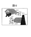
まず、第一のコンテンツを説明する。図12は、図2の2−5に示した表示画面である。この画面上には「トム」と「メアリー」の脳活動状態を反映するオブジェクト「犬」(それぞれ、12−1と12−2)及び、これらのオブジェクトの敵である「烏」(12−3)や「山」(12−4)が表示されている。また、画面の臨場感を高めるために、例えば12−5のような「雲」を表示させていても構わない。
【0042】
具体的には、図13に示すように、「犬」(13−1)は、高さのみを変化させ、一方、「烏」(13−2)は高さと横方向の位置を変化させながら、「犬」の方向へ接近する。また、「雲」は(13−3)は、高さを一定にして「犬」の方向へ接近する。
【0043】
次に、プレーヤーが疲労感を感じずに、画面上のオブジェクトを脳活動を反映する血液量の変化に応じて変化させる方法を、図14により説明する。まず、「犬」や「烏」、「雲」の高さや横方向の位置を初期パラメータとして設定する(14−1)。次に、ゲームを開始する(14−2)。まず、キャラクター「犬」の位置と「烏」の距離を評価する。そして、この差がある一定値よりも遠い場合、即ち、チェックポイントよりも手前を「犬」が飛行しているのであれば、14−3に示した式を用いて、「犬」の高さを制御する。ここでは、例えば、図4に示したような生体組織通過光の揺らぎを表現するために、擬似的に三角関数を用いている。もちろん、この三角関数に限定されるものではなく、例えば、乱数や矩形関数を使用しても、何等問題ない。
【0044】
ここでのチェックポイントとは、通常予め規定されたプログラムで動作しているオブジェクトが生体光計測装置からの信号により動作開始する点を与えるものである。このチェックポイントは、プレーヤーの個性に関するものであるので、プレーヤーからは見えない状態にしてあり、他人に悪用されないように工夫されている。従って、このチェックポイントは、前述のテストタスクで得た信号によって設定されることも可能としている。
【0045】
一方、チェックポイント上に「犬」がいる場合は、この時点での透過光強度と或る判定値を比較する。透過光強度が設定値よりも小さい場合は、脳が活動し血液量が増加していることと対応する。この場合は、脳が活動しているので、その敵「烏」との戦いに勝ったということで、「犬」と「烏」の高さの差を大きくし、敵から回避したという結果にする。一方、これとは逆に、血液量の濃度変化が小さい場合は、敵である「烏」の高度を「犬」へ近接させ、最終的に、「犬」のオブジェクト(キャラクター)の形状(例えば、図13中の風船を破壊)を変化させる。
【0046】
図15に示すような第二のコンテンツでは、トム(15―1)とメアリー(15−2)がボート(15−3)に同乗し、渦巻(15−4)を回避しながら川下りをするシーンを示している。
【0047】
図16に、このボート(15−3)が辿る航路を示す(16−1、16−2、16−3)。この航路は、事前に設定されており、あたかも波に乗って船が進むかのように進む。また、16−4はチェックポイントであり、この場所での血液量変化を用いて、航路16−2を航行するか、渦巻へ導かれる航路16−3へ到達するかを決定する。
【0048】
また、船の舳先の角度(θ)は、図17に示したように、左右に任意に設定することが可能である。具体的には、図18に示した通り、2人のプレーヤーの透過光強度の差を用いて決定することが出来る。
【0049】
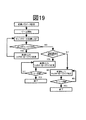
具体的なアルゴリズムのフローチャートを、図19により説明する。まず、ゲームを開始する。そして、ボートの位置を決定する。この位置が、チェックポイント(16−4)まで到達するようにボートの位置を進める。チェックポイントへ到達した場合、航路(16−2)側にいるプレーヤーと航路(16−3)側にいるプレーヤーの脳活動前に対する生体内透過光強度変化を各々計測する。この強度変化の差を計算し、航路16−2側にいるプレーヤーの血液量変化が大きい場合、航路16−3側にいるプレーヤーの血液量変化が大きい場合は、それぞれ、ボートを各航路側へ航行させる。そして、ゴールまで到達するようにボートの位置を変化させる。
【0050】
以上述べた2つのコンテンツでは、各チェックポイントを画面上に呈示する必要性はない。そのため、このようなチェックポイントを発見できたプレーヤーは、楽にゲームを楽しむことが可能になる。
【0051】
上述した遊戯装置を用いてゲームを行うためには、被検査体の皮膚上に光を照射したり光を検出したりする光ファイバを保持する生体装着用の固定具(プローブ)が必要になる。
【0052】
そこで、図20を用いて、本発明に基づく固定具の構造を説明する。図20中の上図、左図は、平面図をそれぞれ側面からみたものであり、右図は、A-A断面を示す。20−1は本体であり、可とう性を有する樹脂部材から構成されている。この本体に、少なくとも一対の照射用光ファイバ(20−2)と検出用光ファイバ(20−3)を保持する光ファイバ保持器(20−4)、及びストッパー(20−5)が設置される。光ファイバ保持器(20−4)は、本体に設けられたガイド(20−10)に沿って一定方向に移動可能に構成されている。ストッパー(20−5)は、本体に固定されているため本体の補強が可能であり、ストッパーとジョイント(20−6)の間の任意の位置に光ファイバ保持器(20−4)の位置を固定することが可能であり、また、この間で光ファイバ保持器をガイド(20−10)上に着脱自在に設置されるように構成されている。本例では、一個の光ファイバ保持器を示したが、本体に複数個の光ファイバ保持器を装填することが可能である。
【0053】
また、脳活動に伴う血液量の変化を検出するためには、照射用光ファイバと検出用光ファイバを30mm離れて被検査体の頭皮上に配置する必要があるため、本体の中心位置から30mm以上離れた位置にストッパーを設置し、このプローブの上下を逆に装着することで、たとえば、任意の前頭葉の頭皮上に配置することが可能になる。
【0054】
また、光ファイバがプレーヤーの視界に入ると鬱陶しいため、本プローブでは、ジョイント(20−6)に固定した光ファイバ押え(20−7)を具備し、照射用光ファイバ、検出用光ファイバとも押える。また、本体はベルトを介して、面ファスナー(20−8、20−9)に接続している。これら画面上に示した2本の面ファスナーを接着することで、頭部に本プローブを固定することが可能になる。
【0055】
【発明の効果】
以上のように、本発明は、手足を使わずに、疲労感を感じずに楽しく使用できる生体光計測法を用いた遊戯装置を提供するものであり、また、これにより、自らの脳の活動状態を把握することが可能になる。例えば、リハビリテーションなどを楽しく実施することも可能であり、福祉面での応用も可能となる。
【図面の簡単な説明】
【図1】生体光計測法に基づく遊戯装置の基本的な装置構成を示す図。
【図2】図1に示した遊戯装置の画面構成を示す図。
【図3】テストタスクを実施する旨をプレーヤーへ呈示する一例を示す図。
【図4】脳活動の計測結果例を示す図。
【図5】脳活動に伴う血液量変化特性の最大値・最小値決定方法を説明するフロー図。
【図6】図2に示した画面構成中のインジケータおよびプレーヤーの顔画像を生体組織透過光強度の変化に応じて変化させる実施例を説明する図。
【図7】脳活動変化の呈示方法の一例を示す図。
【図8】2人のプレーヤーの生体組織透過光強度の時間変化の計測結果例を示す図。
【図9】血液量変化を時間積分特性を示す図。
【図10】ハートマークの点灯結果例を示す図。
【図11】相性の診断結果例を説明する図。
【図12】プレーヤーの疲労を低減したゲームのコンテンツ[1]の例を示す図。
【図13】各キャラクターに関する横スクロール法の例を示す図。
【図14】ゲームコンテンツ[1]のフローチャートを示す図。
【図15】プレーヤーの疲労を低減したゲームのコンテンツ[2]の例を示す図。
【図16】ゲームコンテンツ[2]において、あらかじめ設定したボートの航路と血液量変化を判定するチェックポイントを示す図。
【図17】2人の血液量変化に応じたボートの舳先の角度設定法[1]を示す図。
【図18】2人の血液量変化に応じたボートの舳先の角度設定法[2]を示す図。
【図19】ゲームコンテンツ[2]のフローチャートを示す図。
【図20】本発明に基づく固定具の構造の一例を説明する図。
【符号の説明】
1−1:半導体レーザ、発光ダイオード、ランプに代表される光源、1−2:光ファイバに代表される光導波路、1−3:ゲームのプレーヤー、1−4:光導波路、1−5:フォトダイオード、光電子増倍管に代表される光検出器、1−6:制御装置、1−7:電子計算機、1−8:スピーカー、1−9:画面、2−1:プレーヤーの氏名を表示する場所、2−2:各プレーヤーの生体内を伝播した光透過光強度の変化を図示する表示装置、2−3:各プレーヤーの透過光強度変化を表示する顔画像、2−4:ゲームの進行を表示する表示装置、2−5:表示画面、3−1:表示画面、3−2:キャラクター、3−3:メッセージ、5−1:計測の開始、5−2:透過光強度(V(t))の取得、5−3:透過光強度の判定(最大値?)、5−4:透過光強度の判定(最小値?)、5−5:計測時間の完了の判定、6−1:血液量変化、6−2:インジケータの点滅、6−3:各プレーヤーの顔画像の変化方法、7−1:表示画面、7−2:「ハート」マークのパーツ(1)、7−3:「ハート」マークのパーツ(2)、7−4:「ハート」マークのパーツ(3)、7−5:「ハート」マークのパーツ(4)、7−6:「ハート」マークのパーツ(5)、7−7:「ハート」マークのパーツ(6)、7−8:「ハート」マークのパーツ(7)、7−9:「ハート」マークのパーツ(8)、9−1:図2中のトムの血液量変化を時間積分した特性、9−2:図2中のメアリーの血液量変化を時間積分した特性、10−1:ハートマークの最も内側(図7の7−5や7−9に相当する)が点灯した状態、11−1:計測終了時にランプ7−5のみ(1つ)が点灯した場合、11−2:計測終了時にランプ7−5と7−4が点灯した場合、11−3:計測終了時にランプ7−5、7−4、7−3が点灯した場合、11−4:計測終了時にランプ7−5、7−4、7−3、7−2が点灯した場合、11−5:2人の結果の一致度などに応じた相性の判定結果を告知方法の実施例、12−1:「トム」の脳活動状態を反映するオブジェクト「犬」、12−2:「メアリー」の脳活動状態を反映するオブジェクト「犬」、12−3:オブジェクトの敵である「烏」、12−4:オブジェクトの敵である「山」、12−5:雲、13−1:犬、13−2:烏、13−3:雲、14−1:「犬」や「烏」、「雲」の高さや横方向の位置を初期パラメータとして設定、14−2:ゲームの開始、14−3:犬の高さの計算式、15−1:トム、15−2:メアリー、15−3:ボート、15−4:渦巻、16−1:ボート(15−3)が辿る航路(1)、16−2:ボート(15−3)が辿る航路(2)、16−3:ボート(15−3)が辿る航路(3)、16−4:チェックポイント、20−1:本体、20−2:照射用光ファイバ、20−3:検出用光ファイバ、20−4:光ファイバ保持器、20−5:ストッパー、20−6:ジョイント、20−7:光ファイバ押え、20−8:面ファスナー、20−9:面ファスナー、20−10:ガイド。[0001]
BACKGROUND OF THE INVENTION
The present invention relates to a biological light measurement method for measuring a metabolite inside a living body using light, and more particularly to a game apparatus using the biological light measurement method.
[0002]
[Prior art]
By measuring localized brain functions and inputting them to external devices, computers, games, environmental control devices, learning level determination devices, vehicle alarm devices, medical diagnostic and alarm devices, lie detectors, intentions Japanese Unexamined Patent Publication No. 9-149894 has proposed a biological input device and a biological control device using an optical biological measurement method for controlling a display device, an information transmission device, and the like. Hereinafter, this proposal will be described.
[0003]
In order to irradiate the object to be inspected, a light source typified by a semiconductor laser, a light emitting diode, and a lamp and an optical waveguide typified by an irradiating optical fiber (collectively, a light irradiator) To do. The wavelength of light used for the measurement is optimally the light having a wavelength of about 800 nanometers, which is highly permeable to living tissue, but is not limited to this wavelength band. Both ends of the optical waveguide are in contact with the light source and the skin of the object to be inspected, respectively. The light irradiated to the living body is strongly scattered by the living tissue. However, some of the scattered light passes through the cerebral cortex where higher brain functions such as movement, sensation, and language are concentrated, and reaches the scalp about 30 millimeters away from the light irradiation position (for adults). To do. In order to detect the intensity of light propagated in the living body at this place, a photodetector is arranged. This photodetector is composed of an optical waveguide typified by an optical fiber and a photoelectric element typified by a photodiode and a photomultiplier tube in contact with one end thereof. Using this photodetector, an optical signal is converted into an electrical signal. This electrical signal is processed using an electronic computer.
[0004]
Here, it is assumed that the brain is activated by moving the body (hand, foot, and these fingers, etc.), thinking about things, or thinking. When the brain is active, the blood volume in the cerebral cortex changes (increases or decreases) in order to supply oxygen and glucose to the active site of the brain. When using near-infrared light (wavelength near 800 nanometers) for measurement, hemoglobin in blood (oxygenated hemoglobin, reduced hemoglobin) absorbs this light used for measurement, so the amount of light reaching the detection optical fiber is Decreases as hemoglobin increases with brain activity. For this reason, the detected change in light intensity reflects brain activity. By measuring the change in the intensity of light and controlling the computer using the measurement result, an input device that controls the computer by measuring human thoughts reflecting the mental state and brain activity is realized.
[0005]
[Problems to be solved by the invention]
In the above proposal, a device configuration capable of detecting a brain activity and realizing a game (game device) is disclosed. However, in order to realize an actual game device, in addition to the above examples, it is necessary that various people can use the game device without feeling tired.
[0006]
Accordingly, an object of the present invention has been made paying attention to such a point, and provides a game apparatus using a biological light measurement method that can be used happily without feeling a sense of fatigue without using a limb. Moreover, the fixing tool for biological mounting | wearing used for it is provided.
[0007]
[Means for Solving the Problems]
Hereinafter, in order to achieve the above object, a solution means based on the present invention will be described.
[0008]
First, the optical state of individuals, such as the structure of the human brain and the color of the skin, is different. For this reason, even if the player is irradiated with light having the same intensity, the detected light intensity (passing light intensity) is different. Therefore, in the present invention, even if there is an individual difference in light transmission characteristics, the intensity of light that has passed through the living body is displayed on the screen, and content that allows the player to enjoy the game is provided.
[0009]
Second, a method for presenting brain activity results to a player is provided. Human brain activity is generally invisible and is measured using light in the present invention. However, when brain activity is measured using light, the change in transmitted light intensity is extremely small. Therefore, the present invention provides a game apparatus that can present the brain activity to the player even with a small change in transmitted light intensity.
[0010]
Thirdly, in this game device, the state of the object displayed on the screen is changed according to the measurement result of the brain activity. However, the continuous activity of the brain (always using the head) give. Therefore, in the present invention, a period in which the state of an object displayed on the screen changes according to a signal reflecting brain activity, and a period in which the state changes according to an arbitrary signal emitted from an electronic computer separately from brain activity. Provided is an amusement device that can be set and enjoy a game without continuously activating the brain.
[0011]
Fourthly, if the activity of a person's brain is, for example, a frontal lobe that is considered to be a part reflecting emotions, there is a difference unique to each person. Therefore, the present invention provides a biological light measurement fixture (probe) capable of irradiating and detecting light at an arbitrary location on the frontal lobe.
[0012]
As described above, the present invention includes a light irradiator that irradiates light on a living body, a light detector that detects light passing through the living body irradiated from the light irradiator, and the intensity of light detected by the light detector. A signal processing unit that processes the signal, and a display unit that displays a result processed by the signal processing unit, and according to the result of the test task performed on the living body, Provided is a game apparatus using a biological light measurement method, characterized in that a display range of intensity change is set.
[0013]
In addition, the present invention processes a light irradiator that irradiates light on a living body, a light detector that detects light emitted from the light irradiator and propagated through the living body, and a light intensity signal detected by the light detector. Signal processing unit and a display unit for displaying the result processed by the signal processing unit, time-integrating the intensity change of the light propagated in the living body, and displaying the integration result on the screen of the display unit Provided is a game apparatus using a biological light measurement method characterized in that it is configured to be reflected in an object.
[0014]
In addition, the present invention processes a light irradiator that irradiates light on a living body, a light detector that detects light emitted from the light irradiator and propagated through the living body, and a light intensity signal detected by the light detector. A signal processing unit, and a display unit for displaying a result processed by the signal processing unit, using an intensity signal of light propagated in the living body and a signal emitted by the signal processing unit at an arbitrary time interval An amusement device using a biological light measurement method, characterized in that the state of an object displayed on a display unit changes.
[0015]
The present invention also provides a light irradiator that irradiates light on a living body, a light detector that detects light passing through the living body irradiated from the light irradiator, and an intensity signal of light detected by the light detector. A signal processing unit that processes the signal and a display unit that displays a result processed by the signal processing unit, and at least one of the objects displayed on the screen of the display unit is transmitted through the living body. The living body light measurement method is used, in which a period that changes in accordance with a change in intensity of the object and a period in which the state of the object changes in accordance with an arbitrary signal emitted by the signal processing unit is used. Provide an amusement device.
[0016]
Further, the present invention is characterized in that, in the above configuration, the display range of the light intensity of the transmitted light to be displayed on the screen of the display unit is determined based on the maximum value and the minimum value of the detected light intensity of the transmitted light. A game apparatus using the biological light measurement method is provided.
[0017]
Furthermore, this invention irradiates from the 1st light irradiation device which irradiates light on the 1st biological body, the 2nd light irradiation device which irradiates light on the 2nd biological body, and the 1st light irradiation device. A first photodetector for detecting light propagated through the first living body, a second photodetector for detecting light irradiated from the second light irradiator and propagated through the second living body, A signal processing unit that processes the intensity signal of the light detected by the first and second photodetectors, and a display unit that displays a result of processing by the signal processing unit; The intensity of the light propagated through the time is integrated over time, and the integration result is reflected in the object displayed on the screen of the display unit to display the degree of compatibility between the first and second living bodies. Provided is an amusement device using the characteristic biological light measurement method.
[0018]
Furthermore, the present invention provides a flexible resin comprising an optical fiber holder including at least a pair of irradiation optical fibers and a detection optical fiber, and a guide for making the optical fiber holder movable in a certain direction. There is provided a fixture for a game apparatus using a biological light measurement method, characterized in that the optical fiber holder is detachably installed on a guide of a resin member.
[0019]
DETAILED DESCRIPTION OF THE INVENTION
Hereinafter, the form of the Example of the game device based on this invention is demonstrated in order.
[0020]
FIG. 1 shows a basic device configuration of a game device according to the present invention. Reference numeral 1-1 denotes a light source represented by a semiconductor laser, a light emitting diode, and a lamp. These light sources irradiate the game player (1-3) using an optical waveguide (1-2) typified by an optical fiber. Specifically, the tip of the optical fiber is brought into contact with the player's skin. In the present invention, the embodiment will be described assuming that the number of players is two. However, in the embodiment similar to the present invention, it is possible to carry out similarly even with one player or three or more players.
[0021]
The light propagated through the player is detected using the optical waveguide shown in 1-4 as in the light irradiation method. The arrangement interval between the optical fiber shown in 1-2 and the optical waveguide shown in 1-4 can be arbitrarily set. For example, when detecting brain activity in adults, the 27 mm (millimeter) interval is appropriate because the paper “Applied Optics (Applied Optics)” published by the American Optical Society magazine, pp. 6692 to 6698. N. C. Bruce is described as an “experimental study of the effect of the experimental study of the effect of absorbing and transmitting inclusions in high scattering medium”.
[0022]
The optical waveguide shown in 1-4 is connected to a photodetector (1-5) represented by a photodiode and a photomultiplier tube. By using this photodetector, the intensity of light propagated in the living body is converted into an electrical signal.
[0023]
Next, the configuration of the control device (1-6) and the electronic computer (1-7) constituting the signal processing unit will be described. The control device is electrically connected to the light source (1-1) and the photodetector (1-5). As a result, the intensity of the light source can be changed, or the intensity of the light propagated in the living body can be taken into this control device. This control device outputs a measurement result signal to the electronic computer (1-7). The output of the electronic computer (1-7) is sent to a display unit such as a speaker (1-8), a screen (1-9) or the like. As a result, it is possible to convert the intensity change of the light propagated in the living body into the content to be processed in the electronic computer and present it to the player (1-3). The display unit may be included in the electronic computer (1-7) or may be separate.
[0024]
In this embodiment, the number of players is two. In biological measurement methods using light, for example, it is possible to measure changes in blood volume in multiple people at the same time using a small device, compared to other biological measurement methods using magnets or radiation. is there. For this reason, as described above, it is possible to simultaneously measure changes in blood volume inside the heads of two people. Therefore, there is no problem that two or more players described in this embodiment can use the game apparatus at the same time. In the present invention, the number of players is limited to two, and examples will be described hereinafter.
[0025]
Next, an embodiment relating to the screen configuration relating to the screen (1-9) will be described with reference to FIG. Reference numeral 2-1 denotes a place where the names of the players are displayed. In this embodiment, the names of the players are “Tom” and “Mary”. In the figure, five round bars (2-2) displayed on the left and right are display devices (indicators) illustrating changes in the intensity of light transmitted through the living body of each player using the measuring device described in FIG. ). In the present embodiment, the transmitted light intensity is divided into five and the transmitted light intensity of each player is displayed. The number of divisions is not limited to five. Moreover, the usage method of this indicator is later mentioned using another drawing.
[0026]
Reference numeral 2-3 in FIG. 2 is a face image that displays a change in transmitted light intensity of each player (Tom and Mary). That is, the state of the face image changes according to the change in the light intensity that has passed through the living tissue. This face image state changing method will also be described later with reference to another drawing. Reference numeral 2-4 denotes a display device that displays the progress of the game, and presents to the player which scene the game is currently in, according to the development of the game scene. Reference numeral 2-5 denotes a display screen on which a moving image is displayed. The image displayed on the display screen will be described with reference to another drawing.
[0027]
Next, with reference to FIGS. 3, 4, 5, and 6, an example of content that allows a large number of players having different optical states to enjoy a game will be described.
[0028]
FIG. 3 shows an embodiment in which a player is first informed that a test task is to be performed using the screen shown in FIG. The characteristic of light propagating in a living body mainly depends on optical property values, ie, light scattering coefficient and light absorption coefficient in the living body. In addition, the response to the movement of an object, that is, a physical property value such as agility varies depending on a person. In addition, characteristics of brain activity (time dependency of blood volume change) vary among individuals. Therefore, as shown in FIG. 3, the start of the test task is notified to the player. In this embodiment, the character (3-2) and the message (3-3) are displayed in the display screen (3-1). There is a method of presenting the message on the screen as shown in this figure. Furthermore, using the speaker (1-8) shown in FIG. There is no problem even if it is used and presented to the player.
[0029]
Next, a measurement result example of brain activity is shown using FIG. This measurement result is a detection result of the light passing through the living tissue converted into an electrical signal by the control device (1-6) in FIG. In this measurement result, the brain activity was started 10 seconds after the player started the measurement. Then, as the blood volume increases, the light used for measurement is absorbed by the blood, so that the intensity of the light that has passed through the living tissue decreases. Further, when the brain activity was terminated 30 seconds after the start of measurement, the blood volume returned to the state before the brain activity, and thus the transmitted light intensity increased to the state before the brain activity. “MAX” and “min” shown in FIG. 4 indicate “maximum value” and “minimum value”, respectively.
[0030]
Next, a method for determining these maximum and minimum values will be described with reference to FIG. First, measurement is started (5-1). Next, the transmitted light intensity (V (t)) is acquired by the control device (1-6) (5-2). It is sequentially determined whether the detected transmitted light intensity is the maximum value or the minimum value (5-3, 5-4). As a result, it is possible to quantitatively obtain the intensity of light transmitted through the living tissue, which is unique to the player, and the change in light intensity associated with brain activity. Then, it is determined whether the measurement time is completed (5-5). For example, in the embodiment shown in FIG. 4, the measurement time is 50 seconds. Then, the display method on the indicator is determined.
[0031]
First, the display range
width = (MAX-min) / number ……… Formula (1)
And decide.
[0032]
Then, the display range of the indicators shown in FIG. 2 (five in total, numbers are assigned as 1, 2, 3, 4, 5 from the lower indicators) is determined as follows.
Indicator 1:
V (t) <min + width ……… Formula (2)
Indicator 2:
min + width <V (t) <min + 2 × width ......... Formula (3)
Indicator 3:
min + 2 × width <V (t) <min + 3 × width ……… Formula (4)
Indicator 4:
min + 3 × width <V (t) <min + 4 × width ……… Formula (5)
Indicator 5:
min + 4 × width <V (t) ......... Formula (6)
Then, as shown in FIG. 6, it is possible to control the blinking of the indicator (6-2) indicated by 2-2 in FIG. 2 in accordance with the blood volume change (6-1). Further, it is possible to change the face image of each player shown in FIG. 2 in the same way (in this embodiment, the face color is changed) (6-3).
[0033]
By using the above method, it becomes possible to grasp the changes in transmitted light intensity inherent in human tissue and brain light due to brain activity, and the transmitted light intensity of the two people and their changes are completely different Even so, the change in the blood volume is displayed on the indicator in the screen shown in FIG. 2, and the player can also play the game while actually grasping the change.
[0034]
Next, with reference to FIGS. 7, 8, 9, 10, and 11, there is provided a method of a game apparatus that can present the brain activity to the player even with a small change in blood volume. Reference numeral 7-1 denotes a display screen, and 7-2, 7-3, 7-4, 7-5, 7-6, 7-7, 7-8, and 7-9 are parts of a "heart" mark. . The color of these parts changes according to the activity of the brain so that the fluorescent lamps blink.
[0035]
FIG. 8 is a graph showing temporal changes in the transmitted light intensity of the living tissue of two players (Tom and Mary). As these two graphs show, the change in the intensity of the detection light is as small as 10 percent at the maximum. Therefore, the blood volume change shown in FIG. 8 is integrated.
[0036]
An example of the integration result is shown in FIG. 9-1 and 9-2 in FIG. 9 indicate characteristics obtained by time-integrating the blood volume changes of Tom and Mary in FIG. 2, respectively. FIG. 10 shows the result of changing the state of the heart mark indicated by 7-1 in FIG. 7 corresponding to the characteristics shown in FIG. 9.
[0037]
The relationship between FIG. 9 and FIG. 10 will be described. First, when the integrated value of Tom's blood volume change is 0 or more and 10 or less, it corresponds to the innermost part of the heart mark (corresponding to 7-5 or 7-9 in FIG. 7) as 10-1 in FIG. ) Lights up. FIG. 10 shows an example of a blinking state of the heart lamp at a time interval of 10 seconds from t = 0 to t = 50. When the integral value increases, a lamp in a wide area blinks (the number of blinking lamps increases).
[0038]
Next, an embodiment of a method for determining the result after the measurement is completed will be described with reference to FIG. “1” (11-1) of Tom in the table in FIG. 11 indicates a case where only (one) lamp 7-5 is turned on at the end of measurement. Similarly, “2” (11-2) is lamps 7-5 and 7-4, and “3” (11-3) is 7-5, 7-4, 7-3, “4” (11-4). ) Indicates the case where 7-5, 7-4, 7-3, and 7-2 are lit. Similarly, Mary's “1”, “2”, “3”, and “4” are the same. And as shown to 11-5, according to the coincidence degree of a result of two persons, etc., the determination result is notified about the degree of compatibility. This notification method has no problem even if it is a sound method using a speaker shown in 1-8 in FIG. 1 or a visual method using a screen shown in 1-9. .
[0039]
Furthermore, as a method for confirming agility, a player's response to lighting of light or sound from a speaker is measured. This characteristic is reflected in a checkpoint described later.
[0040]
Next, two game contents in which the player's fatigue is reduced are shown below and will be described with reference to FIGS. 12 to 14 and FIGS. 15 to 19, respectively.
[0041]
First, the first content will be described. FIG. 12 shows the display screen shown in 2-5 of FIG. On this screen, objects “dogs” (12-1 and 12-2, respectively) reflecting the brain activity states of “Tom” and “Mary”, and “烏” (12-3) that is the enemy of these objects are displayed. ) Or “mountain” (12-4). Further, in order to enhance the realistic sensation of the screen, for example, a “cloud” such as 12-5 may be displayed.
[0042]
Specifically, as shown in FIG. 13, the “dog” (13-1) changes only the height, while the “dog” (13-2) changes the height and the lateral position. Approach in the direction of “dog”. The “cloud” (13-3) approaches the direction of the “dog” with a constant height.
[0043]
Next, a method of changing an object on the screen in accordance with a change in blood volume reflecting brain activity without causing the player to feel tired will be described with reference to FIG. First, the height and lateral position of “dog”, “烏”, and “cloud” are set as initial parameters (14-1). Next, the game is started (14-2). First, evaluate the distance between the position of the character “dog” and “烏”. If this difference is farther than a certain value, that is, if the “dog” is flying in front of the check point, the height of the “dog” is calculated using the formula shown in 14-3. To control. Here, for example, a pseudo trigonometric function is used to express the fluctuation of the light passing through the living tissue as shown in FIG. Of course, it is not limited to this trigonometric function. For example, there is no problem even if a random number or a rectangular function is used.
[0044]
Here, the check point gives a point at which an object that is normally operating in accordance with a pre-defined program starts to operate in response to a signal from the biological light measurement device. Since this check point relates to the individuality of the player, the check point is hidden from the player and is devised so as not to be misused by others. Therefore, this check point can be set by a signal obtained by the above-described test task.
[0045]
On the other hand, when there is a “dog” on the check point, the transmitted light intensity at this point is compared with a certain determination value. If the transmitted light intensity is smaller than the set value, this corresponds to the fact that the brain is active and the blood volume is increasing. In this case, because the brain is active, winning the battle with the enemy “Samurai” increased the difference in height between “Dog” and “Samurai” and resulted in avoidance from the enemy. To do. On the other hand, if the change in blood volume concentration is small, the altitude of the enemy “烏” is brought close to “dog” and finally the shape of the object (character) of “dog” (for example, , Destroy the balloon in FIG.
[0046]
In the second content as shown in FIG. 15, Tom (15-1) and Mary (15-2) board the boat (15-3) and go down the river while avoiding the spiral (15-4). Shows the scene.
[0047]
FIG. 16 shows the routes that this boat (15-3) follows (16-1, 16-2, 16-3). This route is set in advance, and proceeds as if the ship travels on a wave. Reference numeral 16-4 denotes a check point, and it is determined whether to navigate the route 16-2 or reach the route 16-3 led to the spiral by using the blood volume change at this place.
[0048]
Further, the ship's tip angle (θ) can be arbitrarily set to the left and right as shown in FIG. Specifically, as shown in FIG. 18, it can be determined using the difference in transmitted light intensity between the two players.
[0049]
A specific algorithm flowchart will be described with reference to FIG. First, the game is started. Then, the position of the boat is determined. The position of the boat is advanced so that this position reaches the check point (16-4). When the check point is reached, the in-vivo transmitted light intensity change before the brain activity of the player on the route (16-2) side and the player on the route (16-3) side is measured. When the difference in the intensity change is calculated and the blood volume change of the player on the route 16-2 side is large, or the blood volume change of the player on the route 16-3 side is large, the boat is moved to each route side. Sail. Then, the position of the boat is changed so as to reach the goal.
[0050]
In the two contents described above, there is no need to present each checkpoint on the screen. Therefore, a player who can find such a checkpoint can easily enjoy the game.
[0051]
In order to play a game using the above-described game machine, a living body mounting fixture (probe) that holds an optical fiber that irradiates light on the skin of the object to be inspected or detects light is required. .
[0052]
Then, the structure of the fixture based on this invention is demonstrated using FIG. The upper view and the left view in FIG. 20 are plan views as seen from the side, and the right view shows the AA cross section. Reference numeral 20-1 denotes a main body, which is composed of a resin member having flexibility. An optical fiber holder (20-4) and a stopper (20-5) for holding at least a pair of the irradiation optical fiber (20-2) and the detection optical fiber (20-3) are installed in the main body. . The optical fiber holder (20-4) is configured to be movable in a certain direction along a guide (20-10) provided in the main body. Since the stopper (20-5) is fixed to the main body, the main body can be reinforced, and the position of the optical fiber holder (20-4) can be set at an arbitrary position between the stopper and the joint (20-6). The optical fiber holder can be fixed on the guide (20-10) while being detachable. In this example, one optical fiber holder is shown, but it is possible to load a plurality of optical fiber holders in the main body.
[0053]
Further, in order to detect a change in blood volume associated with brain activity, it is necessary to dispose the irradiation optical fiber and the detection
[0054]
Also, since the optical fiber is annoying when it enters the player's field of view, this probe has an optical fiber presser (20-7) fixed to the joint (20-6), and can hold both the irradiation optical fiber and the detection optical fiber. . Moreover, the main body is connected to the hook-and-loop fastener (20-8, 20-9) via the belt. By bonding the two surface fasteners shown on these screens, the probe can be fixed to the head.
[0055]
【The invention's effect】
As described above, the present invention provides a game apparatus using a biological light measurement method that can be used happily without feeling tired without using limbs. It becomes possible to grasp the state. For example, rehabilitation can be performed happily, and welfare applications are possible.
[Brief description of the drawings]
FIG. 1 is a diagram showing a basic device configuration of a game device based on a biological light measurement method.
FIG. 2 is a view showing a screen configuration of the game apparatus shown in FIG. 1;
FIG. 3 is a diagram showing an example of presenting to a player that a test task is to be performed.
FIG. 4 is a diagram showing a measurement result example of brain activity.
FIG. 5 is a flowchart for explaining a method for determining the maximum and minimum values of blood volume change characteristics associated with brain activity.
6 is a view for explaining an embodiment in which the indicator in the screen configuration shown in FIG. 2 and the face image of the player are changed according to the change in the transmitted light intensity of the living tissue.
FIG. 7 is a diagram showing an example of a method for presenting changes in brain activity.
FIG. 8 is a diagram showing an example of a measurement result of a temporal change in transmitted light intensity of biological tissue of two players.
FIG. 9 is a diagram showing a time integration characteristic of blood volume change.
FIG. 10 is a diagram showing an example of the result of lighting a heart mark.
FIG. 11 is a diagram for explaining an example of a compatibility diagnosis result.
FIG. 12 is a diagram showing an example of game content [1] in which player fatigue is reduced.
FIG. 13 is a diagram showing an example of a horizontal scroll method for each character.
FIG. 14 is a view showing a flowchart of game content [1].
FIG. 15 is a diagram showing an example of game content [2] with reduced player fatigue.
FIG. 16 is a diagram illustrating check points for determining a preset boat route and blood volume change in the game content [2].
FIG. 17 is a view showing a boat tip angle setting method [1] according to changes in blood volume of two people.
FIG. 18 is a view showing a boat tip angle setting method [2] according to changes in blood volume of two people.
FIG. 19 is a view showing a flowchart of game content [2].
FIG. 20 is a view for explaining an example of the structure of a fixture according to the present invention.
[Explanation of symbols]
1-1: Light source represented by semiconductor laser, light emitting diode, and lamp, 1-2: Optical waveguide represented by optical fiber, 1-3: Game player, 1-4: Optical waveguide, 1-5: Photo Diode, photodetector represented by photomultiplier tube, 1-6: control device, 1-7: electronic calculator, 1-8: speaker, 1-9: screen, 2-1: player name is displayed Location: 2-2: Display device illustrating changes in transmitted light intensity propagated in each player's body, 2-3: Face image displaying changes in transmitted light intensity of each player, 2-4: Progress of game 2-5: display screen, 3-1: display screen, 3-2: character, 3-3: message, 5-1: start of measurement, 5-2: transmitted light intensity (V ( t)), 5-3: determination of transmitted light intensity (maximum value?), 5- 4: Determination of transmitted light intensity (minimum value?), 5-5: Determination of completion of measurement time, 6-1: Blood volume change, 6-2: Indicator blinking, 6-3: Face image of each player Change method, 7-1: display screen, 7-2: parts of “heart” mark (1), 7-3: parts of “heart” mark (2), 7-4: parts of “heart” mark (3 ), 7-5: “Heart” mark parts (4), 7-6: “Heart” mark parts (5), 7-7: “Heart” mark parts (6), 7-8: “Heart” ”Mark part (7), 7-9:“ Heart ”mark part (8), 9-1: time integral of Tom's blood volume change in FIG. 2, 9-2: Mary in FIG. 10-1: The innermost part of the heart mark (corresponding to 7-5 and 7-9 in FIG. 7) 11-1: When only the lamp 7-5 is turned on at the end of measurement, 11-1: When the lamps 7-5 and 7-4 are turned on at the end of measurement, 11-3: Measurement When lamps 7-5, 7-4, and 7-3 are lit at the end, 11-4: When lamps 7-5, 7-4, 7-3, and 7-2 are lit at the end of measurement, 11-5 : Example of a method for notifying the determination result of compatibility according to the degree of coincidence of the results of two persons, 12-1: Object “dog” reflecting the brain activity state of “Tom”, 12-2: “Mary” Object “dog” reflecting the brain activity state, 12-3: “烏” that is the enemy of the object, 12-4: “mountain” that is the enemy of the object, 12-5: cloud, 13-1: dog, 13 -2: Samurai, 13-3: Clouds, 14-1: Initial height and lateral position of "dog", "Samurai", and "Clouds" 14-2: Start of game, 14-3: Formula of dog height, 15-1: Tom, 15-2: Mary, 15-3: Boat, 15-4: Swirl, 16- 1: route (1) followed by boat (15-3), 16-2: route (2) followed by boat (15-3), 16-3: route (3), 16 followed by boat (15-3) -4: check point, 20-1: main body, 20-2: irradiation optical fiber, 20-3: detection optical fiber, 20-4: optical fiber holder, 20-5: stopper, 20-6: joint 20-7: Optical fiber presser, 20-8: Hook fastener, 20-9: Hook fastener, 20-10: Guide.
Claims (2)
該光照射器から照射され前記頭部内を伝播した通過光を検出する光検出器と、
該光検出器で検出した光の強度信号を処理する信号処理部と、
該信号処理部にて処理した結果を画面上に表示する表示部と、
前記光照射器と前記光検出器を前記頭部に取り付けるための固定具とを有し、
該固定具は、少なくとも一対の光照射用光ファイバと検出用光ファイバとを備えた光ファイバ保持器と、該保持器を一定方向に移動可能ならしめるガイドを備え、円弧の形状の、当該光ファイバ保持器を前記頭部に固定する可とう性の樹脂部材とを有し、前記保持器が前記樹脂部材のガイド上に着脱自在に設置されるよう構成し、かつ、
前記頭部へのテストタスクの実施結果に応じて、前記表示部の画面上に表示する前記通過光の強度変化の表示範囲を設定するよう構成して、
前記プレーヤーが画面上に表示されるオブジェクトを用いてゲームを行えるようにしたことを特徴とする生体光計測法を用いた遊戯装置。A light irradiator for irradiating the player's head with light;
A photodetector for detecting passing light irradiated from the light irradiator and propagated in the head ;
A signal processing unit for processing an intensity signal of light detected by the photodetector;
A display unit that displays on the screen a result processed by the signal processing unit;
A fixture for attaching the light irradiator and the photodetector to the head ;
The fixture is provided with an optical fiber retainer provided with at least a pair of optical fibers for detecting light illumination optical fiber, the makes it movable guides the cage in a fixed direction, the arc-shaped, the optical A flexible resin member that fixes a fiber retainer to the head, and the retainer is configured to be detachably installed on a guide of the resin member; and
According to the test task execution result to the head , configured to set the display range of the intensity change of the passing light to be displayed on the screen of the display unit,
A game apparatus using a biological light measurement method, characterized in that the player can play a game using an object displayed on a screen.
Priority Applications (3)
| Application Number | Priority Date | Filing Date | Title |
|---|---|---|---|
| JP2001022923A JP3950634B2 (en) | 2001-01-31 | 2001-01-31 | Game device using biological light measurement method |
| US09/939,601 US6657183B2 (en) | 2001-01-31 | 2001-08-28 | Amusement system using living body measurement by light, head setter for the amusement system, and program for use in the amusement system |
| US10/674,412 US20040065812A1 (en) | 2001-01-31 | 2003-10-01 | Amusement system using living body measurement by light, head setter for the amusement system, and program for use in the amusement system |
Applications Claiming Priority (1)
| Application Number | Priority Date | Filing Date | Title |
|---|---|---|---|
| JP2001022923A JP3950634B2 (en) | 2001-01-31 | 2001-01-31 | Game device using biological light measurement method |
Publications (3)
| Publication Number | Publication Date |
|---|---|
| JP2002224089A JP2002224089A (en) | 2002-08-13 |
| JP2002224089A5 JP2002224089A5 (en) | 2005-10-13 |
| JP3950634B2 true JP3950634B2 (en) | 2007-08-01 |
Family
ID=18888266
Family Applications (1)
| Application Number | Title | Priority Date | Filing Date |
|---|---|---|---|
| JP2001022923A Expired - Fee Related JP3950634B2 (en) | 2001-01-31 | 2001-01-31 | Game device using biological light measurement method |
Country Status (2)
| Country | Link |
|---|---|
| US (2) | US6657183B2 (en) |
| JP (1) | JP3950634B2 (en) |
Families Citing this family (10)
| Publication number | Priority date | Publication date | Assignee | Title |
|---|---|---|---|---|
| JP4160838B2 (en) | 2003-02-17 | 2008-10-08 | 株式会社日立製作所 | Biological light measurement device |
| JP4896874B2 (en) * | 2004-05-11 | 2012-03-14 | コーニンクレッカ フィリップス エレクトロニクス エヌ ヴィ | Measuring head for non-invasive blood analysis |
| WO2006011076A1 (en) * | 2004-07-22 | 2006-02-02 | Koninklijke Philips Electronics N.V. | Strategic use of bio-sensor information in multi-player computer game |
| JP4590555B2 (en) * | 2004-09-02 | 2010-12-01 | 国立大学法人長岡技術科学大学 | Sensitive state discrimination method and apparatus |
| JP4991431B2 (en) | 2007-07-31 | 2012-08-01 | 株式会社日立製作所 | External environment control device based on brain function measurement |
| JP5443075B2 (en) * | 2009-06-30 | 2014-03-19 | 株式会社日立製作所 | Game system, biological light measurement device |
| JP5328700B2 (en) * | 2010-03-10 | 2013-10-30 | 株式会社コナミデジタルエンタテインメント | GAME DEVICE, GAME DEVICE CONTROL METHOD, AND PROGRAM |
| CN103476337A (en) * | 2011-04-15 | 2013-12-25 | 株式会社日立医疗器械 | Biophotonic measurement device, biophotonic measurement device operating method, and biophotonic measurement data analysis and display method |
| JP2015039542A (en) * | 2013-08-22 | 2015-03-02 | セイコーエプソン株式会社 | Pulse wave measurement apparatus |
| JP7316331B2 (en) * | 2021-09-02 | 2023-07-27 | 株式会社Screenホールディングス | SUBSTRATE PROCESSING APPARATUS AND SUBSTRATE PROCESSING METHOD |
Family Cites Families (11)
| Publication number | Priority date | Publication date | Assignee | Title |
|---|---|---|---|---|
| US4281645A (en) * | 1977-06-28 | 1981-08-04 | Duke University, Inc. | Method and apparatus for monitoring metabolism in body organs |
| US5111817A (en) * | 1988-12-29 | 1992-05-12 | Medical Physics, Inc. | Noninvasive system and method for enhanced arterial oxygen saturation determination and arterial blood pressure monitoring |
| JPH05300887A (en) * | 1992-04-27 | 1993-11-16 | Shimadzu Corp | Apparatus for measuring amount of cerebral blood |
| US5853370A (en) * | 1996-09-13 | 1998-12-29 | Non-Invasive Technology, Inc. | Optical system and method for non-invasive imaging of biological tissue |
| US5339810A (en) * | 1993-05-03 | 1994-08-23 | Marquette Electronics, Inc. | Pulse oximetry sensor |
| US6095974A (en) * | 1995-07-21 | 2000-08-01 | Respironics, Inc. | Disposable fiber optic probe |
| US6001065A (en) * | 1995-08-02 | 1999-12-14 | Ibva Technologies, Inc. | Method and apparatus for measuring and analyzing physiological signals for active or passive control of physical and virtual spaces and the contents therein |
| JP3543453B2 (en) | 1995-12-01 | 2004-07-14 | 株式会社日立製作所 | Biological input device using optical biometric method |
| US5974338A (en) * | 1997-04-15 | 1999-10-26 | Toa Medical Electronics Co., Ltd. | Non-invasive blood analyzer |
| WO1999062399A1 (en) * | 1998-06-03 | 1999-12-09 | Masimo Corporation | Stereo pulse oximeter |
| US6215403B1 (en) * | 1999-01-27 | 2001-04-10 | International Business Machines Corporation | Wireless monitoring system |
-
2001
- 2001-01-31 JP JP2001022923A patent/JP3950634B2/en not_active Expired - Fee Related
- 2001-08-28 US US09/939,601 patent/US6657183B2/en not_active Expired - Lifetime
-
2003
- 2003-10-01 US US10/674,412 patent/US20040065812A1/en not_active Abandoned
Also Published As
| Publication number | Publication date |
|---|---|
| JP2002224089A (en) | 2002-08-13 |
| US20020100867A1 (en) | 2002-08-01 |
| US20040065812A1 (en) | 2004-04-08 |
| US6657183B2 (en) | 2003-12-02 |
Similar Documents
| Publication | Publication Date | Title |
|---|---|---|
| US20020095089A1 (en) | Amusement system based on an optical instrumentation method for the living body | |
| JP3950634B2 (en) | Game device using biological light measurement method | |
| JP5295584B2 (en) | Blood flow measuring device and brain activity measuring device using blood flow measuring device | |
| US20110046491A1 (en) | System, Optode And Cap For Near-Infrared Diffuse-Optical Function Neuroimaging | |
| JPWO2010004940A1 (en) | Blood vessel characteristic measuring device and blood vessel characteristic measuring method | |
| CN106943117A (en) | Biometric information measuring device | |
| JPH04261646A (en) | Calibration tester for pulse oximeter | |
| GB2422660A (en) | Device for monitoring body functions | |
| JP2010240298A (en) | Biological light measuring device and biological light measuring method | |
| JP2018521744A (en) | Phototherapy device with integrated urine collector and sensor that allows side effects to be reduced | |
| US10226206B2 (en) | Systems and methods for measuring neonatal cerebral oxygenation | |
| JP3779134B2 (en) | Biological light measurement device | |
| US11109782B2 (en) | Systems and methods for measuring neonatal cerebral oxygenation | |
| US6723047B1 (en) | Volition induction apparatus and input/output apparatus which use optical measuring instrument, and recording medium | |
| JP2011010714A (en) | Optical biometric device, game system and biosignal generation method | |
| ATE134850T1 (en) | NON-INVASIVE METHOD FOR IN VIVO DETERMINATION OF ARTERIAL BLOOD OXYGEN SATURATION RATE AND DEVICE THEREOF | |
| US8639306B2 (en) | Noninvasive eye-property monitoring, including aqueous-humor glucose monitoring as an indication of blood glucose level | |
| JP2002224089A5 (en) | ||
| JPH078473A (en) | Measurement device | |
| JP6657202B2 (en) | Flexible optical generator for pulse oximetry. | |
| KR20110006032A (en) | Blood flow measuring machine and brain activity measuring machine using blood flow measuring machine | |
| Nishimura et al. | A new approach to functional near-infrared technology | |
| JPH0759782A (en) | Living body light measuring apparatus | |
| US10206578B1 (en) | Combination arterial and vein transillumination device using yellow-orange, lime green and amber LED lights | |
| WO2013150629A1 (en) | Light measurement system |
Legal Events
| Date | Code | Title | Description |
|---|---|---|---|
| A521 | Request for written amendment filed |
Free format text: JAPANESE INTERMEDIATE CODE: A523 Effective date: 20050601 |
|
| A621 | Written request for application examination |
Free format text: JAPANESE INTERMEDIATE CODE: A621 Effective date: 20050601 |
|
| RD02 | Notification of acceptance of power of attorney |
Free format text: JAPANESE INTERMEDIATE CODE: A7422 Effective date: 20050601 |
|
| A977 | Report on retrieval |
Free format text: JAPANESE INTERMEDIATE CODE: A971007 Effective date: 20060428 |
|
| A131 | Notification of reasons for refusal |
Free format text: JAPANESE INTERMEDIATE CODE: A131 Effective date: 20060905 |
|
| A131 | Notification of reasons for refusal |
Free format text: JAPANESE INTERMEDIATE CODE: A131 Effective date: 20061121 |
|
| A521 | Request for written amendment filed |
Free format text: JAPANESE INTERMEDIATE CODE: A523 Effective date: 20070117 |
|
| A131 | Notification of reasons for refusal |
Free format text: JAPANESE INTERMEDIATE CODE: A131 Effective date: 20070213 |
|
| A521 | Request for written amendment filed |
Free format text: JAPANESE INTERMEDIATE CODE: A523 Effective date: 20070305 |
|
| TRDD | Decision of grant or rejection written | ||
| A01 | Written decision to grant a patent or to grant a registration (utility model) |
Free format text: JAPANESE INTERMEDIATE CODE: A01 Effective date: 20070410 |
|
| A61 | First payment of annual fees (during grant procedure) |
Free format text: JAPANESE INTERMEDIATE CODE: A61 Effective date: 20070423 |
|
| R150 | Certificate of patent or registration of utility model |
Free format text: JAPANESE INTERMEDIATE CODE: R150 Ref document number: 3950634 Country of ref document: JP Free format text: JAPANESE INTERMEDIATE CODE: R150 |
|
| FPAY | Renewal fee payment (event date is renewal date of database) |
Free format text: PAYMENT UNTIL: 20110427 Year of fee payment: 4 |
|
| FPAY | Renewal fee payment (event date is renewal date of database) |
Free format text: PAYMENT UNTIL: 20120427 Year of fee payment: 5 |
|
| FPAY | Renewal fee payment (event date is renewal date of database) |
Free format text: PAYMENT UNTIL: 20120427 Year of fee payment: 5 |
|
| FPAY | Renewal fee payment (event date is renewal date of database) |
Free format text: PAYMENT UNTIL: 20130427 Year of fee payment: 6 |
|
| FPAY | Renewal fee payment (event date is renewal date of database) |
Free format text: PAYMENT UNTIL: 20140427 Year of fee payment: 7 |
|
| LAPS | Cancellation because of no payment of annual fees |