JP3946830B2 - Thermally activated steam trap - Google Patents
Thermally activated steam trap Download PDFInfo
- Publication number
- JP3946830B2 JP3946830B2 JP25318597A JP25318597A JP3946830B2 JP 3946830 B2 JP3946830 B2 JP 3946830B2 JP 25318597 A JP25318597 A JP 25318597A JP 25318597 A JP25318597 A JP 25318597A JP 3946830 B2 JP3946830 B2 JP 3946830B2
- Authority
- JP
- Japan
- Prior art keywords
- spring
- valve
- temperature
- springs
- steam trap
- Prior art date
- Legal status (The legal status is an assumption and is not a legal conclusion. Google has not performed a legal analysis and makes no representation as to the accuracy of the status listed.)
- Expired - Lifetime
Links
Images

Landscapes
- Temperature-Responsive Valves (AREA)
Description
【0001】
【発明の属する技術分野】
本発明は、たとえば蒸気配管の下流側に設けられ、蒸気と復水が混入した流体が所定温度以下のときに開弁して、流体を外部に排出するようにした熱応動式蒸気トラップに関するものである。
【0002】
【従来の技術】
従来、この種の熱応動式蒸気トラップは、ボディの内部に、弁座面をもつ弁座部材と、一端に前記弁座面に着座する弁体を、他端にストッパを設けた弁棒と、その外周に嵌め込まれたバイメタルコラムからなる感温駆動体と、弁棒の外周で感温駆動体とストッパとの間に介装された単一の圧縮ばねを備えている。
【0003】
そして、ボディ内の流体温度が所定温度以上のとき、感温駆動体が熱膨張することにより、圧縮ばねを介して弁棒が閉弁方向に移動し、その弁体が弁座面に着座する。この着座により、熱膨張を続ける感温駆動体と弁棒のストッパの間で圧縮ばねが圧縮され、この圧縮ばねにより弁体が弁座面に圧接されて閉弁状態が維持され、所定温度以上の流体の外部排出を阻止する。
【0004】
以上の状態から、復水の量が増加してボディ内の流体が所定温度以下に低下したとき、感温駆動体の熱膨張力が低下し、これに伴い圧縮ばねが伸長することにより、弁棒に対する閉弁方向への押圧力が低下する。これら感温駆動体が弁棒を閉弁方向に移動させようとする力に対し、弁棒の全体に作用するボディ内の流体圧力などにより弁棒を開弁方向に移動させようとする力が打ち勝ったとき、弁棒が開弁方向に移動して弁体が弁座面から離れ、所定温度以下の流体をボディから外部に排出する。
【0005】
【発明が解決しようとする課題】
ところで、以上のような熱応動式蒸気トラップにおいては、多量の復水の滞溜防止および省資源の観点から、流体の圧力変化にかかわらず、蒸気飽和温度に近く、かつこの温度よりも一定値だけ低い温度で開弁する特性、つまり、蒸気飽和温度曲線に沿った開弁特性を具備させることが望ましい。しかしながら、従来のように、感温駆動体とストッパの間に圧縮ばねを1つだけ介装した場合、蒸気飽和温度曲線に沿った望ましい開弁特性を得るのが難しく、往々にして、復水の滞溜量が増加する問題がある。
【0006】
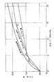
すなわち、縦軸に温度、横軸に絶対圧力を取った図5に示すように、蒸気飽和温度曲線Aが圧力上昇に伴って徐々に勾配が小さくなる曲線となるのに対し、圧縮ばね1つの場合の開弁特性曲線Dは、圧縮ばねが作用し始めるX1点の圧力までの開弁温度が、感温駆動体の伸張力によって一義的に決まり、X1点の圧力を越えた領域でも、圧縮ばねが1つであるために、開弁特性曲線Dの勾配が直線的になる。したがって、開弁特性曲線DはX1点の1か所でのみ山形に折れ曲がった直線からなるので、開弁特性曲線Dを蒸気飽和温度曲線Aに十分沿わせることができない。
【0007】
そこで、本発明の目的は、蒸気飽和温度曲線に沿った良好な開弁特性を得て、復水の滞留量を減少させることにある。
【0008】
【課題を解決するための手段】
上記目的を達成するため、請求項1記載の発明の特徴は、感温駆動体とストッパとの間に介装する圧縮ばね体として、ばね定数の異なる複数のばねを用い、これらばねを直列に接続させている。
【0009】
以上の熱応動式蒸気トラップでは、流体の温度が所定温度以上のとき、感温駆動体が熱膨張することにより、弁棒が閉弁方向に移動し、その弁体が通路の弁座面に着座する。この着座により、熱膨張を続ける感温駆動体とストッパの間に介装した複数のばねがそれぞれ圧縮され、これらのばねにより弁体が弁座面に圧接されて閉弁し、所定温度以上の流体の外部排出を阻止する。
【0010】
一方、流体が所定温度以下になると、感温駆動体の熱膨張力が低下し、これに伴い各ばねが伸長して弁棒に対する閉弁方向への押圧力が低下する。これら感温駆動体が弁棒を閉弁方向に移動させようとする力に対し、弁棒や弁体に作用する流体の圧力により弁棒が開弁方向に移動しようとする力が打ち勝ったとき、この弁棒が開弁方向に移動し、弁体が弁座面から離間することにより開弁して、所定温度以下の流体を外部に排出する。
【0011】
このとき、圧縮ばね体として、ばね定数の異なる複数のばねを用い、これら各ばねを直列に接続させているので、流体の蒸気飽和温度曲線に沿った開弁特性が得られる。つまり、流体の温度上昇に伴う感温駆動体の熱膨張により、まず最初に、ばね定数の小さい(弱い)ばねが主として圧縮されるので、開弁特性曲線は図5における勾配が大きいものとなる。このばね定数の小さいばねの圧縮が終了すると、ばね定数の大きい方のばねのみの圧縮に移る。この時点、つまりばね定数変化点以降は、ばね定数が大きいから、開弁特性曲線の勾配が小さくなる。したがって、開弁特性曲線は前記ばね定数変化点で折れ曲がった、上に凸な形状となるから、曲線状の蒸気飽和温度曲線に沿わせることが可能となる。
【0012】
本発明の実施形態では、複数のばねを弁棒の軸方向に沿って直列に配置している。また、別の実施形態では、複数のばねを互いに異なる直径として径方向に重合状に配置し、隣接する2つのばねの一端部と他方の他端部を連結部材により連結している。これらの構成によれば、所期の目的が簡単な構成で達成される。また、後者によれば、直径の異なる各ばねを重合状に配置することにより、圧縮ばね体の全体長さがより短くなる。
【0013】
請求項4記載の発明の特徴は、感温駆動体とストッパとの間に介装する圧縮ばね体として、複数のばねを並列配置したものを用い、ばね定数が小さい方のばねを大きい方のばねよりも早期に圧縮が始まるように設定している。
【0014】
この並列ばね型の熱応動式蒸気トラップでは、前記場合と同様に、流体の温度や圧力に基づき弁体が開弁したり閉弁したりする。このとき、各ばねを並列に配置し、かつばね定数が小さい方のばねを大きい方のばねよりも早期に圧縮が始まるように設定しているから、まず最初に、ばね定数の小さいばねが圧縮され、つづいて、ばね定数の大きい方のばねの圧縮が始まる。したがって、やはり、開弁特性曲線は複数のばねの圧縮が始まるばね定数変化点で折れ曲がった、上に凸な形状となるから、曲線状の蒸気飽和温度曲線に沿わせることが可能となる。さらに、各ばねを並列に配置して圧縮ばね体を構成したから、請求項1記載の発明よりも圧縮ばね体の全体長さを短くできる。
【0015】
本発明の実施形態では、圧縮ばね体として、直径の異なる複数のばねを用い、これらを径方向に重合状に配置して、ばね定数の小さい方のばねの自然長さを大きい方のばねよりも長くしている。この構成によれば、簡単な構成で所期の目的が達成される。
【0016】
【発明の実施の形態】
以下、第1の発明にかかる一実施形態を図面に基づいて説明する。
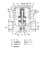
図1に示す熱応動式蒸気トラップは、左右両側に流入口1aと排出口1bをもつボディ1と、このボディ1の上部の開口部に着脱可能にねじ連結されたカバー2とを備えている。前記ボディ1の内部には、その底部にねじ結合された弁座部材3と、この弁座部材3を上下方向に貫挿し、下端側に弁体41を取付けた弁棒4が配置されている。
【0017】
前記弁座部材3は、その上部側に弁棒4をガイドするスリーブ5を圧力により固定するとともに、内方下部側には弁体41を収納する下部開放の弁室30を形成し、この弁室30の上方入口側には、下部側が径大で上部側が径小となるテーパ面からなる弁座面31を形成している。また、弁座面31の上方側には、上流端がボディ1内に常時開口する縦孔および横孔からなる通路32が設けられ、弁室30の周壁には、弁室30と排出口1bに開口する複数の流出孔33が形成されている。
【0018】
前記弁体41には、前記弁座面31に当接するテーパ状の当接部42が形成されている。また、弁棒4におけるスリーブ5の上部側には、後述する圧縮ばね体8の上部側を受けるワッシャ状のばね受け部材6を配置している。
【0019】
さらに、前記スリーブ5の外周には、複数のバイメタルを重合したバイメタルコラムのような感温駆動体7を上下移動可能に嵌め込む。このバイメタルコラム7は、Cuのような高膨張部材71とNiのような低膨張部材72とを重合させ、高膨張部材71が外部側に、低膨張部材72が内部側に位置するように2枚一組として重ね合わせ、この2枚一組とされた複数組を前記スリーブ5に嵌め込んで、バイメタルコラム7の下端部を弁座部材3の上面に支持させている。
【0020】
また、前記スリーブ5の外周囲でばね受け部材6とバイメタルコラム7の上端部との間には、圧縮ばね体8を介装する。
【0021】
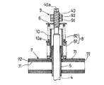
この圧縮ばね体8としては、図2で明らかなように、ばね定数の大きな第1コイルばね81と、これよりもばね定数の小さな第2コイルばね82を用いる。そして、第1コイルばね81を下方のバイメタルコラム7側に、第2コイルばね82を上方のばね受け部材6側に置いて直列状に配置する。また、各コイルばね81,82の内部でスリーブ5との間には、筒状のストッパスリーブ10を配置しており、バイメタルコラム7の熱膨張に伴い各コイルばね81,82が、後述するストッパ91に当接したばね受け部材6とバイメタルコラム7との間で圧縮されるとき、まず最初に、ばね定数の小さな第2コイルばね82がストッパスリーブ10とばね受け部材6との間で圧縮され、その後は、ばね力の大きな第1コイルばね81のみが作用する(圧縮される)。このストッパスリーブ10の長さ方向中間には、径方向に延びるつば部10aを一体に形成し、このつば部10aを各コイルばね81,82の対向端部に位置させることにより、各コイルばね81,82を直列状に接続させる。
【0022】
図3の実施形態では、前記圧縮ばね体8として、直径が小さくてばね定数の大きな第1コイルばね83と、直径が大きくてばね定数の小さな第2コイルばね84を用いている。そして、前記スリーブ5の外周囲でばね受け部材6とバイメタルコラム7の間に、第1コイルばね83が内部側に、第2コイルばね84が外部側に位置するように重合して、圧縮ばね体8の全体高さを低くし、熱応動式蒸気トラップの全高寸法を小さくするようにしている。
【0023】
各コイルばね83,84の間には、両者を直列状に接続するための連結部材11を設けている。この連結部材11は、筒体11aの上端部に径方向内方に向かうつば部11bを、下端部に径方向外方に向かうつば部11cをそれぞれ一体に形成して、前記筒体11aをコイルばね83,84の間に介装させた状態で、これらコイルばね83,84の上下端部を各つば部11b,11cに当接させて連結することにより、各コイルばね83,84を直列状に接続している。この連結部材11も上記したストッパスリーブ10と同様な機能を備えている。
【0024】
各図においては、ボディ1の内部に、バイメタルコラム7の熱膨張時における変形量を制御可能な調整部材9を設け、熱応動式蒸気トラップを蒸気配管に取り付ける前に、カバー2を開放した状態で調整部材9を操作して、バイメタルコラム7の熱膨張による閉弁温度を適宜設定(初期設定)することにより、排水する流体の温度を任意に調整できるようにしている。
【0025】
この調整部材9は、前記弁棒4の上部側に設けたねじ部40に螺合され、ばね受け部材6が当接するナットからなるストッパ91と、ねじ部40のストッパ91の上部側に螺合させるロックナット92を備えている。そして、ねじ部40の上端に設けた操作溝40aにドライバなどを差し込んで螺回させながら、ねじ部40に対するストッパ91の取付位置を調整し、つまり、バイメタルコラム7の熱膨張に伴い各コイルばね81〜84を介してばね受部材6が上動されるときの上限位置を調整することにより、弁体41の閉弁温度を任意に調整する。この後、ロックナット92を緊締して、ストッパ91の位置ずれを防止する。
【0026】
次に、以上の構成とした熱応動式蒸気トラップの作用について説明する。
図1において、蒸気または蒸気と復水が混入した流体が、流入口1aからボディ1内に流入する。流入した流体の温度が所定温度以上のとき、バイメタルコラム7の各熱膨張要素(各バイメタル組)が熱膨張して上下方向(軸方向)に湾曲状に変形する。このバイメタルコラム7の変形により、図2の場合は、軸方向に直列に配置された第1,第2コイルばね81,82がガイド部材10とばね受け部材6を伴いながら上動する。また、図3の場合は、径方向に重合配置された第1,第2コイルばね83,84が連結部材11とばね受け部材6を伴いながら上動する。
【0027】
図1のように、ばね受け部材6がストッパ91に当接して、弁棒4を上方の閉弁方向へと移動させ、その弁体41の当接部42が弁座部材3の弁座面31に着座する。このとき、各コイルばね81,82および83,84は、当接部42の弁座面31への着座により、熱膨張を続けるバイメタルコラム7とストッパ91に当接したばね受け部材6との間で圧縮される。
【0028】
以上の状態から、ボディ1内に流入する復水の量が増加して、ボディ1内の流体が所定温度以下に低下すると、バイメタルコラム7の上下方向の変形量が小となり、これに伴い各コイルばね81,82および83,84が伸長することにより、弁棒4に対する開弁方向への押圧力が増加する。バイメタルコラム7により弁棒4を閉弁方向に移動させようとする力に対し、各コイルばね81,82または83,84の上面、弁棒4の頂面および弁体41のテーパ面41aに作用するボディ1内の流体圧力や自重などで弁棒4を下方の開弁方向に移動させようとする力が打ち勝ったとき、この弁棒4が開弁方向に移動して弁体41が弁座面31から離間することにより開弁し、所定温度以下の復水を連通路33を経て排出口1bから外部に排出する。
【0029】
このとき、各コイルばね81,82および83,84として、それぞればね定数の異なるものを使用し、これら各コイルばね81,82および83,84を直列に接続しているので、流体の蒸気飽和温度曲線に沿った開弁特性が得られる。この点に関しては後で説明する。
【0030】
次に、第2発明の実施形態を図4に基づいて説明する。
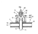
この実施形態では、ばね受け部材6とバイメタルコラム7の間に介装する圧縮ばね体8として、直径が小さくてばね定数の大きな第1コイルばね85と、直径が大きく、ばね定数が小さくて自然長さが第1コイルばね85よりも長い第2コイルばね86とを用いる。そして、前記スリーブ5の外周囲でばね受け部材6とバイメタルコラム7の間に、第1コイルばね85が内部側に、第2コイルばね86が外部側に位置するように重合して並列に配置する。
【0031】
また、各コイルばね85,86の間には、筒状のストッパスリーブ12を配置している。
【0032】
次に、以上の第2発明による作用について説明する。
図1の流入口1aからボディ1内に流入した流体の温度が所定温度以上のとき、図4のバイメタルコラム7の熱膨張により、各コイルばね85,86、ガイド部材12およびばね受け部材6が上動し、このばね受け部材6がストッパ91に当接することにより、弁棒4が閉弁方向に押し上げられて、その弁体41の当接部42が弁座面31に着座する。上記の絶対圧力がある特定の温度よりも低い場合は、第2のばね86のみが圧縮され、前記特定の温度よりも高い場合は、第1ばね85と第2ばね85が共に圧縮される。
【0033】
また、流体が所定温度以下になって、バイメタルコラム7の熱膨張力が低下したとき、弁棒4や弁体41に作用する流体の圧力により各コイルばね85,86が伸長して開弁方向への押圧力が増加し、弁棒4が開弁方向に移動して開弁状態となる。
【0034】
図5は、縦軸に温度(℃)を、横軸に絶対圧力(Kg・f/cm2)をとった流体の蒸気飽和温度曲線Aと、第1および第2発明による開弁特性曲線Bを示している。また、同図には、圧縮ばねを1個だけ用いた従来の開弁特性曲線Dも示されている。上記各曲線BDよりも下側の領域で開弁状態が維持される。また、各曲線B,Dにおいて、X1は各コイルばねの効きが開始する点を示している。このばね動作開始点X1まではばね体8とストッパ91との間に隙間が存在するために、ばね体8は圧縮されない。ばね動作開始点X1よりも高圧力側では、ばね体8のばね力が作用し、ばね定数が小さいほど、つまりばねが弱いほど曲線の勾配が大きくなる。
【0035】
この図から明らかなように、従来例を示す曲線Dは、前述のとおり、ばね動作開始点X1よりも低圧力側の開弁特性は、感温駆動体の伸張力により一義的に決まり、動作開始点X1よりも高圧力側は1つの圧縮ばねのばね定数により直線的に変化するので、蒸気飽和温度曲線Aに十分沿わせることは難しい。
【0036】
これに対し、図1〜3に示した第1発明の場合は、圧縮ばね体8として、ばね定数の異なる複数のばね81〜84を直列接続したものを用いている。したがって、流体の温度上昇に伴って動作開始点X10を越えると、まず最初に、ばね定数の小さいばね82,84が主として圧縮されるので、図5に示す開弁特性曲線Bは勾配が比較的大きいものとなる。このばね定数の小さいばね82,84の圧縮が終了した時点X2で、ばね定数の大きい方のばね81,83のみの圧縮に移り、ばね定数が変化する。このばね定数変化点X2以降は、ばね定数が大きいから、開弁特性曲線Bの勾配が小さくなる。したがって、開弁特性曲線Bは、前記動作開始点X0bと前記ばね定数変化点X2とで折れ曲がった、上に凸な形状となるから、曲線状の蒸気飽和温度曲線Aに沿わせることが可能となる。つまり、X10とX2の2点で折れ曲がった形状となるので、圧力上昇と共に温度上昇の勾配が徐々に小さくなる蒸気飽和温度曲線Aに沿わせ易くなる。
【0037】
なお、動作開始点X1,X10の位置は、図2に示したばね受け部材6と調整部材9のストッパ91との間隙の大きさを適宜変更することにより、移動する。
【0038】
また、図4の第2の発明では、2つの第1および第2コイルばね85,86を並列に配置し、ばね定数が小さい方のばね86を大きい方のばね85よりも早期に圧縮が始まるように設定しているから、まず最初に、ばね定数の小さいばね86が圧縮され、つづいて、ばね定数の大きい方のばね85の圧縮が始まる。したがって、図5に示した開弁特性曲線Bと同様な特性となり、動作開始点X10と両方のばね85,86の圧縮が始まるばね定数変化点X2の2か所で折れ曲がった、上に凸な形状となるから、曲線状の蒸気飽和温度曲線Aに沿わせることが可能となる。
【0039】
以上の各実施形態では、圧縮ばね体8として、2つのコイルばねを用いたが、本発明では、3つ以上のコイルばねを用いてもよい。
【0040】
【発明の効果】
以上のように、本発明によれば、感温駆動体とストッパとの間に介装する圧縮ばね体として、ばね定数の異なる複数のばねを用いたことにより、熱応動式蒸気トラップの全高を小さくし、かつ圧縮ばね体の信頼性を高めながら、蒸気飽和温度曲線に近づけた開弁特性を得て、復水の滞留量を減少させることができる。
【図面の簡単な説明】
【図1】第1の発明の一実施形態である熱応動式蒸気トラップの縦断面図である。
【図2】図1の要部を取出して示す拡大縦断面図である。
【図3】他の実施形態を示す縦断面図である。
【図4】第2の発明の一実施形態である熱応動式蒸気トラップの縦断面図である。
【図5】蒸気飽和温度曲線と本発明による開弁特性曲線を示す特性図である。
【符号の説明】
1…ボディ、4…弁棒、41…弁体、7…感温駆動体、8…圧縮ばね体、81〜84…ばね、91…ストッパ、11…連結部材。[0001]
BACKGROUND OF THE INVENTION
The present invention relates to a thermally responsive steam trap that is provided on the downstream side of a steam pipe, for example, and opens when the fluid mixed with steam and condensate is below a predetermined temperature and discharges the fluid to the outside. It is.
[0002]
[Prior art]
Conventionally, this type of thermally responsive steam trap has a valve seat member having a valve seat surface inside the body, a valve body seated on the valve seat surface at one end, and a valve rod provided with a stopper at the other end. And a temperature-sensitive driving body formed of a bimetal column fitted on the outer periphery thereof, and a single compression spring interposed between the temperature-sensitive driving body and the stopper on the outer periphery of the valve rod.
[0003]
When the fluid temperature in the body is equal to or higher than the predetermined temperature, the temperature-sensitive driving body is thermally expanded, so that the valve rod moves in the valve closing direction via the compression spring, and the valve body is seated on the valve seat surface. . By this seating, the compression spring is compressed between the temperature-sensitive driving body that continues thermal expansion and the stopper of the valve stem, and the valve body is pressed against the valve seat surface by this compression spring to maintain the valve closed state. Prevents external fluid discharge.
[0004]
From the above state, when the amount of condensate increases and the fluid in the body falls below the predetermined temperature, the thermal expansion force of the temperature-sensitive drive body decreases, and the compression spring expands accordingly. The pressing force in the valve closing direction against the rod decreases. In contrast to the force that the temperature sensitive drive body moves the valve stem in the valve closing direction, the force that moves the valve rod in the valve opening direction due to the fluid pressure in the body acting on the entire valve rod When it is overcome, the valve stem moves in the valve opening direction, the valve body is separated from the valve seat surface, and the fluid having a predetermined temperature or less is discharged from the body to the outside.
[0005]
[Problems to be solved by the invention]
By the way, in the heat-responsive steam trap as described above, from the viewpoint of preventing a large amount of condensate from accumulating and saving resources, the steam saturation temperature is close to a constant value regardless of the fluid pressure change. It is desirable to provide a valve opening characteristic along a vapor saturation temperature curve, that is, a valve opening characteristic at a temperature as low as possible. However, when only one compression spring is interposed between the temperature-sensitive drive body and the stopper as in the prior art, it is difficult to obtain a desired valve opening characteristic along the steam saturation temperature curve. There is a problem that the amount of stagnation increases.
[0006]
That is, as shown in FIG. 5 where the vertical axis represents temperature and the horizontal axis represents absolute pressure, the vapor saturation temperature curve A becomes a curve that gradually decreases as the pressure rises. In the case of the valve opening characteristic curve D, the valve opening temperature up to the pressure at the point X1 at which the compression spring starts to act is uniquely determined by the extension force of the temperature-sensitive driving body, and even in the region where the pressure exceeds the point X1 Since there is one spring, the gradient of the valve opening characteristic curve D becomes linear. Therefore, since the valve opening characteristic curve D is a straight line bent at only one point X1, the valve opening characteristic curve D cannot sufficiently follow the steam saturation temperature curve A.
[0007]
Therefore, an object of the present invention is to obtain a good valve opening characteristic along the steam saturation temperature curve and to reduce the condensate retention amount.
[0008]
[Means for Solving the Problems]
In order to achieve the above object, the invention according to claim 1 is characterized in that a plurality of springs having different spring constants are used as a compression spring body interposed between the temperature-sensitive drive body and the stopper, and these springs are connected in series. Connected.
[0009]
In the above heat-responsive steam trap, when the fluid temperature is equal to or higher than a predetermined temperature, the temperature sensing driver thermally expands to move the valve stem in the valve closing direction, and the valve body moves to the valve seat surface of the passage. Sit down. By this seating, a plurality of springs interposed between the temperature-sensitive drive body and the stopper that continue thermal expansion are respectively compressed, and the valve body is pressed against the valve seat surface by these springs to close the valve, and the temperature exceeds a predetermined temperature. Prevent external discharge of fluid.
[0010]
On the other hand, when the fluid becomes a predetermined temperature or less, the thermal expansion force of the temperature-sensitive drive body is reduced, and accordingly, each spring is extended, and the pressing force in the valve closing direction against the valve rod is reduced. When the force that the valve rod moves in the valve opening direction is overcome by the pressure of the fluid acting on the valve rod or the valve body, against the force that these temperature-sensitive drive bodies move the valve rod in the valve closing direction The valve stem moves in the valve opening direction, and the valve element is opened when the valve element is separated from the valve seat surface, and the fluid having a predetermined temperature or less is discharged to the outside.
[0011]
At this time, a plurality of springs having different spring constants are used as the compression spring body, and these springs are connected in series, so that a valve opening characteristic along the vapor saturation temperature curve of the fluid is obtained. That is, because the thermal expansion of the temperature-sensitive driving body accompanying the temperature rise of the fluid, first, the spring having a small spring constant is mainly compressed, so that the valve opening characteristic curve has a large gradient in FIG. . When the compression of the spring having the smaller spring constant is completed, the compression of only the spring having the larger spring constant is started. At this point, that is, after the spring constant change point, the spring constant is large, so the slope of the valve opening characteristic curve becomes small. Therefore, the valve opening characteristic curve is bent at the spring constant change point and has an upwardly convex shape, so that it is possible to follow the curved steam saturation temperature curve.
[0012]
In the embodiment of the present invention, a plurality of springs are arranged in series along the axial direction of the valve stem. In another embodiment, a plurality of springs are arranged in a radial shape with mutually different diameters, and one end portion and the other end portion of two adjacent springs are connected by a connecting member. According to these configurations, the intended object can be achieved with a simple configuration. Moreover, according to the latter, the whole length of a compression spring body becomes shorter by arrange | positioning each spring from which a diameter differs in superposition | polymerization form.
[0013]
The feature of the invention described in
[0014]
In this parallel spring type thermally responsive steam trap, the valve element opens and closes based on the temperature and pressure of the fluid as in the case described above. At this time, the springs are arranged in parallel, and the spring with the smaller spring constant is set to start compression earlier than the spring with the larger spring. Then, compression of the spring having the larger spring constant starts. Therefore, since the valve opening characteristic curve is bent upward at the spring constant change point where the compression of the plurality of springs starts, the valve opening characteristic curve can follow the curved steam saturation temperature curve. Furthermore, since the springs are arranged in parallel to constitute the compression spring body, the entire length of the compression spring body can be made shorter than that of the invention of claim 1.
[0015]
In the embodiment of the present invention, a plurality of springs having different diameters are used as the compression spring body, and these are arranged in a superposed manner in the radial direction so that the natural length of the spring having the smaller spring constant is larger than that of the larger spring. It is also long. According to this configuration, the intended object can be achieved with a simple configuration.
[0016]
DETAILED DESCRIPTION OF THE INVENTION
An embodiment according to the first invention will be described below with reference to the drawings.
The thermally responsive steam trap shown in FIG. 1 includes a body 1 having an inlet 1a and an
[0017]
The
[0018]
The
[0019]
Further, a temperature-
[0020]
A
[0021]
As apparent from FIG. 2, the
[0022]
In the embodiment of FIG. 3, a
[0023]
Between each
[0024]
In each figure, an
[0025]
The adjusting
[0026]
Next, the operation of the thermally responsive steam trap having the above configuration will be described.
In FIG. 1, steam or a fluid in which steam and condensate are mixed flows into the body 1 from the inflow port 1 a. When the temperature of the fluid that flows in is equal to or higher than a predetermined temperature, each thermal expansion element (each bimetal group) of the
[0027]
As shown in FIG. 1, the
[0028]
From the above state, when the amount of condensate flowing into the body 1 increases and the fluid in the body 1 falls below a predetermined temperature, the amount of deformation in the vertical direction of the
[0029]
At this time, as the coil springs 81, 82 and 83, 84, springs having different spring constants are used, and the coil springs 81, 82, 83, 84 are connected in series. A valve opening characteristic along the curve is obtained. This point will be described later.
[0030]
Next, an embodiment of the second invention will be described with reference to FIG.
In this embodiment, as the
[0031]
A
[0032]
Next, the operation of the above second invention will be described.
When the temperature of the fluid flowing into the body 1 from the inlet 1a in FIG. 1 is equal to or higher than a predetermined temperature, the coil springs 85, 86, the
[0033]
Further, when the fluid becomes a predetermined temperature or less and the thermal expansion force of the
[0034]
FIG. 5 shows a vapor saturation temperature curve A of the fluid with the vertical axis representing temperature (° C.) and the horizontal axis representing absolute pressure (Kg · f / cm 2 ), and the valve opening characteristic curve B according to the first and second inventions. Is shown. The figure also shows a conventional valve opening characteristic curve D using only one compression spring. The valve opening state is maintained in a region below the curves BD. Moreover, in each curve B and D, X1 has shown the point from which the effect of each coil spring starts. Until the spring operation start point X1, there is a gap between the
[0035]
As is clear from this figure, the curve D showing the conventional example shows that, as described above, the valve opening characteristic on the lower pressure side than the spring operation start point X1 is uniquely determined by the extension force of the temperature-sensitive drive body, and the operation Since the high pressure side from the starting point X1 changes linearly by the spring constant of one compression spring, it is difficult to sufficiently follow the steam saturation temperature curve A.
[0036]
On the other hand, in the case of the 1st invention shown in FIGS. 1-3, what connected in series the some spring 81-84 from which a spring constant differs as the
[0037]
The positions of the operation start points X1 and X10 are moved by appropriately changing the size of the gap between the
[0038]
In the second invention of FIG. 4, the two first and second coil springs 85, 86 are arranged in parallel, and the compression of the
[0039]
In each of the above embodiments, two coil springs are used as the
[0040]
【The invention's effect】
As described above, according to the present invention, by using a plurality of springs having different spring constants as the compression spring body interposed between the temperature-sensitive drive body and the stopper, the overall height of the thermally responsive steam trap can be increased. While reducing the size and improving the reliability of the compression spring body, it is possible to obtain a valve opening characteristic close to the steam saturation temperature curve and to reduce the condensate retention amount.
[Brief description of the drawings]
FIG. 1 is a longitudinal sectional view of a thermally responsive steam trap according to an embodiment of the first invention.
FIG. 2 is an enlarged vertical sectional view showing a main part extracted from FIG. 1;
FIG. 3 is a longitudinal sectional view showing another embodiment.
FIG. 4 is a longitudinal sectional view of a thermally responsive steam trap according to an embodiment of the second invention.
FIG. 5 is a characteristic diagram showing a steam saturation temperature curve and a valve opening characteristic curve according to the present invention.
[Explanation of symbols]
DESCRIPTION OF SYMBOLS 1 ... Body, 4 ... Valve rod, 41 ... Valve body, 7 ... Temperature-sensitive drive body, 8 ... Compression spring body, 81-84 ... Spring, 91 ... Stopper, 11 ... Connecting member.
Claims (5)
一端に弁体を有し、他端にストッパが取付けられた弁棒と、
前記流体の熱を受けて熱膨張により前記弁棒の閉弁方向に駆動力を発生する感温駆動体と、
前記弁棒の外周に嵌め込まれて、熱膨張した感温駆動体と前記ストッパとの間で圧縮される圧縮ばね体とを備え、
この圧縮ばね体は、ばね定数の異なる複数のばねが直列に接続されてなる熱応動式蒸気トラップ。A thermally responsive steam trap that opens and closes a fluid passage in accordance with the temperature and pressure of the fluid,
A valve stem having a valve body at one end and a stopper attached to the other end;
A temperature-sensitive driving body that receives the heat of the fluid and generates a driving force in the valve closing direction of the valve stem by thermal expansion;
A compression spring body that is fitted on the outer periphery of the valve stem and compressed between the temperature-sensitive drive body and the stopper, which are thermally expanded;
This compression spring body is a thermally responsive steam trap in which a plurality of springs having different spring constants are connected in series.
一端に弁体を有し、他端にストッパが取付けられた弁棒と、
前記流体の熱を受けて熱膨張により前記弁棒の閉弁方向に駆動力を発生する感温駆動体と、
前記弁棒の外周に嵌め込まれて、熱膨張した感温駆動体と前記ストッパとの間で圧縮される圧縮ばね体とを備え、
この圧縮ばね体は、複数のばねを並列に配置してなり、ばね定数の小さい方のばねが大きい方のばねよりも早期に圧縮が始まるように設定されている熱応動式蒸気トラップ。A thermally responsive steam trap that opens and closes a fluid passage in accordance with the temperature and pressure of the fluid,
A valve stem having a valve body at one end and a stopper attached to the other end;
A temperature-sensitive driving body that receives the heat of the fluid and generates a driving force in the valve closing direction of the valve stem by thermal expansion;
A compression spring body that is fitted on the outer periphery of the valve stem and compressed between the temperature-sensitive drive body and the stopper, which are thermally expanded;
This compression spring body is a thermally responsive steam trap in which a plurality of springs are arranged in parallel, and the spring with the smaller spring constant is set to start compression earlier than the spring with the larger spring constant.
Priority Applications (1)
| Application Number | Priority Date | Filing Date | Title |
|---|---|---|---|
| JP25318597A JP3946830B2 (en) | 1997-04-04 | 1997-09-18 | Thermally activated steam trap |
Applications Claiming Priority (3)
| Application Number | Priority Date | Filing Date | Title |
|---|---|---|---|
| JP8656697 | 1997-04-04 | ||
| JP9-86566 | 1997-04-04 | ||
| JP25318597A JP3946830B2 (en) | 1997-04-04 | 1997-09-18 | Thermally activated steam trap |
Publications (2)
| Publication Number | Publication Date |
|---|---|
| JPH10332081A JPH10332081A (en) | 1998-12-15 |
| JP3946830B2 true JP3946830B2 (en) | 2007-07-18 |
Family
ID=26427676
Family Applications (1)
| Application Number | Title | Priority Date | Filing Date |
|---|---|---|---|
| JP25318597A Expired - Lifetime JP3946830B2 (en) | 1997-04-04 | 1997-09-18 | Thermally activated steam trap |
Country Status (1)
| Country | Link |
|---|---|
| JP (1) | JP3946830B2 (en) |
Cited By (1)
| Publication number | Priority date | Publication date | Assignee | Title |
|---|---|---|---|---|
| CN107063500A (en) * | 2016-10-20 | 2017-08-18 | 云南电网有限责任公司电力科学研究院 | A kind of memory alloy spring fault detector for being used to detect transmission line of electricity tie point |
Families Citing this family (4)
| Publication number | Priority date | Publication date | Assignee | Title |
|---|---|---|---|---|
| JP6322476B2 (en) * | 2014-05-19 | 2018-05-09 | 株式会社テイエルブイ | Float type steam trap |
| KR101484602B1 (en) * | 2014-10-01 | 2015-01-22 | 윤정상 | Steam trap to react actively to the amount of condensed water using a shape memory alloy |
| CN108397685A (en) * | 2018-05-09 | 2018-08-14 | 盐城市大昌石化设备有限公司 | A kind of adjustable constant temperature drain valve |
| CN121429817A (en) * | 2025-12-29 | 2026-01-30 | 浙江纽顿流体控制有限公司 | Sensitive steam condensate temperature control valve |
Family Cites Families (9)
| Publication number | Priority date | Publication date | Assignee | Title |
|---|---|---|---|---|
| JPS434633Y1 (en) * | 1965-02-20 | 1968-02-28 | ||
| JPS5378426A (en) * | 1976-12-22 | 1978-07-11 | Kyokuto Kaihatsu Kogyo Co | Pressure compensatable type flow quantity controlling valve |
| JPS5680589A (en) * | 1979-12-02 | 1981-07-01 | Otani Shigeki | Steam trap |
| DE2948686C2 (en) * | 1979-12-04 | 1983-09-29 | Gestra Kondensatableiter Gmbh & Co Kg, 2800 Bremen | Bimetal controlled condensate drain |
| DE3002294C2 (en) * | 1980-01-23 | 1982-07-29 | Gestra-Ksb-Vertriebsgesellschaft Mbh & Co Kg | Bimetal controlled condensate drain |
| JPH0384286A (en) * | 1989-08-28 | 1991-04-09 | Hitachi Constr Mach Co Ltd | flow control valve |
| JP2503920Y2 (en) * | 1989-11-02 | 1996-07-03 | 旭有機材工業株式会社 | Constant flow valve |
| DE4039766C1 (en) * | 1990-12-13 | 1992-06-04 | Fa. Carl Freudenberg, 6940 Weinheim, De | |
| JP3761985B2 (en) * | 1996-08-05 | 2006-03-29 | 株式会社ミヤワキ | Temperature control trap |
-
1997
- 1997-09-18 JP JP25318597A patent/JP3946830B2/en not_active Expired - Lifetime
Cited By (2)
| Publication number | Priority date | Publication date | Assignee | Title |
|---|---|---|---|---|
| CN107063500A (en) * | 2016-10-20 | 2017-08-18 | 云南电网有限责任公司电力科学研究院 | A kind of memory alloy spring fault detector for being used to detect transmission line of electricity tie point |
| CN107063500B (en) * | 2016-10-20 | 2023-10-20 | 云南电网有限责任公司电力科学研究院 | A memory alloy spring fault indicator for detecting connection points of transmission lines |
Also Published As
| Publication number | Publication date |
|---|---|
| JPH10332081A (en) | 1998-12-15 |
Similar Documents
| Publication | Publication Date | Title |
|---|---|---|
| CN102308152B (en) | Valve with a delta P-function and flow limiting function | |
| JP3946830B2 (en) | Thermally activated steam trap | |
| US4723704A (en) | Bimetal steam trap | |
| KR890000252Y1 (en) | Disc Type Steam Traps | |
| JP3761985B2 (en) | Temperature control trap | |
| US4295605A (en) | Steam traps | |
| KR970002337B1 (en) | Thermally Responsive Steam Traps | |
| JPH06100316B2 (en) | Steam trap | |
| JPH0150800B2 (en) | ||
| JPH0215760B2 (en) | ||
| US3724751A (en) | Disc-type steam trap | |
| US2914251A (en) | Thermostatic steam trap | |
| JPH0469320B2 (en) | ||
| JPH0716159Y2 (en) | Valve made of bimetal which is sensitive to temperature | |
| JPH0828785A (en) | Thermally-actuated steam trap | |
| US895702A (en) | Steam-trap. | |
| JPH0446155Y2 (en) | ||
| GB2076494A (en) | Snap-acting control for fluid- flow valve | |
| CA1122500A (en) | Steam traps | |
| US2253930A (en) | Pressure and temperature relief valve | |
| JPH0520944Y2 (en) | ||
| JP7357904B2 (en) | valve device | |
| JP7277310B2 (en) | valve device | |
| JP2709548B2 (en) | Large capacity steam trap | |
| JPS63259283A (en) | Temperature control valve |
Legal Events
| Date | Code | Title | Description |
|---|---|---|---|
| A621 | Written request for application examination |
Free format text: JAPANESE INTERMEDIATE CODE: A621 Effective date: 20040915 |
|
| A977 | Report on retrieval |
Free format text: JAPANESE INTERMEDIATE CODE: A971007 Effective date: 20070328 |
|
| TRDD | Decision of grant or rejection written | ||
| A01 | Written decision to grant a patent or to grant a registration (utility model) |
Free format text: JAPANESE INTERMEDIATE CODE: A01 Effective date: 20070410 |
|
| A61 | First payment of annual fees (during grant procedure) |
Free format text: JAPANESE INTERMEDIATE CODE: A61 Effective date: 20070412 |
|
| R150 | Certificate of patent or registration of utility model |
Free format text: JAPANESE INTERMEDIATE CODE: R150 |
|
| FPAY | Renewal fee payment (event date is renewal date of database) |
Free format text: PAYMENT UNTIL: 20110420 Year of fee payment: 4 |
|
| FPAY | Renewal fee payment (event date is renewal date of database) |
Free format text: PAYMENT UNTIL: 20110420 Year of fee payment: 4 |
|
| FPAY | Renewal fee payment (event date is renewal date of database) |
Free format text: PAYMENT UNTIL: 20130420 Year of fee payment: 6 |
|
| FPAY | Renewal fee payment (event date is renewal date of database) |
Free format text: PAYMENT UNTIL: 20130420 Year of fee payment: 6 |
|
| FPAY | Renewal fee payment (event date is renewal date of database) |
Free format text: PAYMENT UNTIL: 20140420 Year of fee payment: 7 |
|
| R250 | Receipt of annual fees |
Free format text: JAPANESE INTERMEDIATE CODE: R250 |
|
| R250 | Receipt of annual fees |
Free format text: JAPANESE INTERMEDIATE CODE: R250 |
|
| R250 | Receipt of annual fees |
Free format text: JAPANESE INTERMEDIATE CODE: R250 |
|
| R250 | Receipt of annual fees |
Free format text: JAPANESE INTERMEDIATE CODE: R250 |
|
| EXPY | Cancellation because of completion of term |