JP3945552B2 - Heating element, fixing device and image forming apparatus - Google Patents
Heating element, fixing device and image forming apparatus Download PDFInfo
- Publication number
- JP3945552B2 JP3945552B2 JP16970798A JP16970798A JP3945552B2 JP 3945552 B2 JP3945552 B2 JP 3945552B2 JP 16970798 A JP16970798 A JP 16970798A JP 16970798 A JP16970798 A JP 16970798A JP 3945552 B2 JP3945552 B2 JP 3945552B2
- Authority
- JP
- Japan
- Prior art keywords
- heating element
- insulating substrate
- resistance heating
- heat
- elongated
- Prior art date
- Legal status (The legal status is an assumption and is not a legal conclusion. Google has not performed a legal analysis and makes no representation as to the accuracy of the status listed.)
- Expired - Fee Related
Links
Images


Landscapes
- Fixing For Electrophotography (AREA)
- Control Of Resistance Heating (AREA)
- Resistance Heating (AREA)
Description
【0001】
【発明の属する技術分野】
本発明は、発熱体、これを用いた定着装置および画像形成装置に関する。
【0002】
【従来の技術】
複写機、プリンタまたはファクシミリなどの画像形成装置において、トナーなどの顕画剤を熱定着させるための発熱体として、特開平6−324586号公報に記載のものが知られている。この発熱体は、アルミナセラミックスからなる細長くて薄い絶縁基板に細長い抵抗発熱体を厚膜形成したものである。
【0003】
そうして、この発熱体は、抵抗発熱体の熱容量が小さいために、電源電圧を印加すると、顕画剤の熱定着に寄与する発熱体の作用部が瞬時に所要温度まで昇温する。したがって、この発熱体を画像形成装置などに用いると、ウエイトタイムを短縮できる、待機電力消費がない、画像形成装置などの機内温度上昇を抑制できるなどの利点がある。
【0004】
一方、熱定着用の発熱体には比較的高い電圧を印加して作動させるので、高い耐電圧性を要求される。また、この発熱体は、その表面にポリイミド樹脂などからなる搬送シートが圧接状態で摺接するので、高い耐摩耗性および小さい摩擦抵抗も要求される。これらの要求に応えるために、抵抗発熱体および当該発熱体を形成している方の絶縁基板はガラス質の保護膜で包囲される。
【0005】
さらに、画像形成装置の高速化の要求に対応するべく、抵抗発熱体の発熱量を増大させるために、絶縁基板に窒化アルミニウムを用いるとともに、抵抗発熱体を形成した面の反対面を被定着体に直接または間接的に接触させるようにした発熱体が特開平10−133501号公報に記載されている。窒化アルミニウムは、発熱体を覆って絶縁基板に形成される保護膜のガラスより熱伝導率が大きいので、窒化アルミニウムの絶縁基板を用いた発熱体の場合、絶縁基板を介して被加熱体に伝熱した方が熱効率がよい旨、および抵抗発熱体を形成した方の絶縁基板面すなわち非伝熱面から発生する熱損失も大きくなるので、抵抗発熱体の上から断熱層としてガラス層を形成して熱損失による熱効率の低下を改善する旨上記公報に記載されている。
【0006】
【発明が解決しようとする課題】
ところが、上述した従来の窒化アルミニウムを絶縁基板に用いた発熱体においては、断熱層として熱伝導率が2〜3×10⁻³(cal/cm sec K)程度の通常のガラスを用いているので、窒化アルミニウムの熱伝導率5×10⁻¹(cal/cm sec K)に比較すれば、格段に熱伝導が少ないもののまだ十分満足できる断熱が得られていない。
【0007】
また、上述の従来技術には断熱層としてPI・PFA・PTFEなどの断熱性絶縁樹脂などを用いることも示唆されており、合成樹脂は一般にガラスより熱伝導率が小さいので断熱性の点ではよいが、以下に示す問題がある。
【0008】
すなわち、画像形成装置に供給する被記録材としては、普通紙から葉書のようなサイズの小さい厚手の紙まで種々のサイズおよび厚さの紙などを用いることができればよいが、発熱体をステーに取り付けて、上から加圧しながら定着させるので、被記録材として厚手のものを供給したときに、被記録材が当接した発熱体の部分に局部的な応力が作用するために、絶縁基板が割れやすい。
【0009】
本発明は、窒化アルミニウムを絶縁基板とした場合の非伝熱面から発生する熱損失を通常のガラスを断熱層として用いた場合より一層低減し、また厚手の被記録材を用いても絶縁基板が割れにくい発熱体、これを用いた定着装置および画像形成装置を提供することを目的とする。
【0010】
【課題を達成するための手段】
請求項1の発明の発熱体は、窒化アルミニウムからなる細長い絶縁基板と;絶縁基板の一方の面にその長手方向に沿って形成された細長い抵抗発熱体と;抵抗発熱体の上から絶縁基板の一方の面に形成された金属酸化物からなる中空フィラーを添加して多数の気泡を含有させたガラス膜と;を具備していることを特徴としている。
【0011】
本発明および以下の各発明において、特に指定しない限り用語の定義および技術的意味は次による。
【0012】
(絶縁基板について)
絶縁基板は、抵抗発熱体および抵抗発熱体に付随する導電体パターンおよび端子パターンなどを形成する部分が窒化アルミニウムからなる。なお、絶縁基板は、ドクターブレード法などを用いて薄板状に形成したものを使用することができる。
【0013】
また、絶縁基板の形状は細長くて、なるべくは薄いものであれば、それ以外の形状は自由である。
【0014】
(抵抗発熱体について)
抵抗発熱体は、特に材料、形状、寸法および製法などを問わないが、最適なのは銀・パラジウム系合金を主成分とする導電ペーストをスクリーン印刷法によって印刷、焼成することによって形成した厚膜の抵抗発熱体である。この厚膜の抵抗発熱体によれば、通常多用されているA4やA3サイズを中心とする用紙にトナーを良好に定着させ得るような長寸の発熱体において、抵抗発熱体の抵抗値を所要の昇温が得られるように設計しやすい。
【0015】
また、抵抗発熱体は、1本に限らず複数本が並行して形成されていてもよい。さらに、ほぼ平行に延在する複数本の抵抗発熱体を導電体パターンまたは抵抗発熱体材料により直列接続して蛇行した屈曲状態の形態にしてもよい。
【0016】
(ガラス膜について)
ガラス膜は、絶縁基板と協働して抵抗発熱体を包囲してこれを電気的に絶縁するとともに、抵抗発熱体および抵抗発熱体を配設している絶縁基板の表面を覆って断熱するために用いる。本発明においては、ガラス膜中に後述の手段により多数の気泡を含有させたのが本発明の特徴である。
【0017】
すなわち、多数の気泡を含有させるために、金属酸化物からなる中空フィラーをガラスに添加してこれを実現している。
【0018】
ガラスの種類は、ホウケイ酸系のガラス、ホウケイ酸鉛系のガラス、ホウケイ酸亜鉛系のガラスなどを用いることができる。なお、ホウケイ酸系のガラスおよびホウケイ酸亜鉛系のガラスは、窒化アルミニウムの絶縁基板に対する密着性が相対的に優れている。これに対して、ホウケイ酸鉛系のガラスは、断熱性が相対的に優れている。
【0019】
中空フィラーとしては、アルミナまたはシリカなどからなるものを用いることができる。
【0020】
ガラス膜中に金属酸化物からなる中空フィラーを添加して多数の気泡を含有させたことにより、熱伝導率をガラス単体のときに比較して、数分の一ないし十分の一程度に低減させることができる。
【0021】
(その他の構成について)
抵抗発熱体の温度を一定に維持するために、抵抗発熱体の熱を受ける位置にたとえばサーミスタなどの温度センサを配設することができる。そして、温度センサを温度制御回路に接続する。
【0022】
そうして、温度制御回路は、抵抗発熱体の通電を制御してその発熱量を一定になるようにする。本発明において、温度センサは、抵抗発熱体を形成している方の絶縁基板の面において、なるべく抵抗発熱体に接近した位置に配設することにより、温度センサが板面から突出して熱定着作用を阻害しないようにすることができる。
【0023】
また、要すれば温度ヒューズのような温度過昇防止手段を配設してもよい。
【0024】
さらにまた、本発明の発熱体は、熱定着用として好適であるが、これに限定されるものではなく、あらゆる用途に適応する。
【0025】
(本発明の作用について)
本発明の発熱体は、一方の面に抵抗発熱体を形成した絶縁基板の他方の面を伝熱面として用いる場合に効果的である。すなわち、非伝熱面となる抵抗発熱体を形成した方の面には、金属酸化物からなる中空フィラーを添加して多数の気泡を含有させたガラス膜を形成したので、その熱伝導率がガラス単体の状態より格段に小さくなり、そのため非伝熱面から発生する熱損失が大幅に低減する。
【0026】
したがって、本発明の発熱体は、従来のガラス断熱層を備えた発熱体より高い熱効率を呈する。
【0027】
また、抵抗発熱体は、金属酸化物からなる中空フィラーを添加して多数の気泡を含有させたガラス膜および絶縁基板の協働によって気密に包囲されるので、従来の合成樹脂層より保護が良好であり、このため大気との接触などによって抵抗値が変化するような不都合が生じにくい。すなわち、上記ガラス膜は、断熱層と保護層とを兼ねるものである。
【0028】
請求項2の発明の発熱体は、窒化アルミニウムからなる細長い絶縁基板と;絶縁基板の一方の面にその長手方向に沿って形成された細長い抵抗発熱体と;絶縁基板の他方の面に形成された金属酸化物からなる中空フィラーを添加して多数の気泡を含有させたガラス膜と;を具備していることを特徴としている。
【0029】
本発明は、抵抗発熱体を形成している絶縁基板の一方の面を伝熱面とする場合に好適な発熱体である。したがって、絶縁基板の他方の面に金属酸化物からなる中空フィラーを添加して多数の気泡を含有させたガラス膜を形成することにより、非伝熱面からの熱損失を著しく低減させることができる。
【0030】
また、本発明においては、たとえ抵抗発熱体を形成している一方の面を伝熱面とする場合であったとしても、次に示す有用な作用がある。すなわち、窒化アルミニウムの絶縁基板を伝熱面として用いることにより、抵抗発熱体の長手方向の発熱分布に多少のばらつきがあったとしても、発生熱はまず熱伝導率の大きな絶縁基板に伝熱される結果、発熱体の長手方向に温度の均整化が行われてから被記録材の顕画剤に伝熱されるので、温度分布が均一となり、熱定着の品質が向上する。
【0031】
請求項3の発明の発熱体は、請求項1または2記載の発熱体において、絶縁基板は、多数の気泡を含有させたガラス膜を形成している面が粗面化されていることを特徴としている。
【0032】
窒化アルミニウムの絶縁基板は、アルミナセラミックスに較べると、ガラスとの密着性が良好でない。
【0033】
そこで、本発明においては、絶縁基板の表面を予め粗面化処理しておくことにより、多数の気泡を含有させたガラス膜との密着性を良好にするものである。
【0034】
窒化アルミニウムの絶縁基板の表面の粗面化処理の手段は問わないが、たとえば絶縁基板の成形時に内面を粗面化した金型を用いるか、サンドブラスト、バフ研磨などの機械加工により粗面化することができる。
【0035】
請求項4の発明の発熱体は、窒化アルミニウムからなる細長い絶縁基板と;絶縁基板の一方の面にその長手方向に沿って形成された細長い抵抗発熱体と;抵抗発熱体の上から絶縁基板の一方の面に形成されている柔軟性、耐熱性および断熱性を備えた合成樹脂膜と;を具備していることを特徴としている。
【0036】
「柔軟性を備えている」とは、熱定着時に絶縁基板に加わる応力を適度に吸収し得る程度の柔軟性があることをいう。また、「耐熱性を備えている」とは、発熱体の使用環境の温度および自己の発熱に耐え得る程度であればよい。さらに、「断熱性を備えている」とは、通常のガラスより熱伝導率が小さい程度であればよい。そして、以上の3条件を備えている合成樹脂としては、たとえばシリコーン樹脂などが該当する。
【0037】
そうして、本発明においては、窒化アルミニウムからなる絶縁基板の抵抗発熱体を形成している面の反対面を伝熱面にして被記録材を加熱するに当たり、抵抗発熱体を形成している方の非伝熱面を上記合成樹脂膜によって熱絶縁することにより、熱損失を低減して発熱体の熱効率を高めることができる。また、これとともに、合成樹脂膜が柔軟性を備えているので、被記録材が厚手のものであることなどにより、応力が絶縁基板に対して局部的に加えられても、合成樹脂膜の部分で応力を適度に吸収するので、絶縁基板の割れが少なくなる。
【0038】
請求項5の発明の発熱体は、窒化アルミニウムからなる細長い絶縁基板と;絶縁基板の一方の面にその長手方向に沿って形成された細長い抵抗発熱体と;他方の面に形成されている柔軟性、耐熱性および断熱性を備えた合成樹脂膜と;を具備していることを特徴としている。
【0039】
本発明は、絶縁基板の抵抗発熱体を形成している方の面を伝熱面として被記録材などへ伝熱するのに好適な構成を規定している。
【0040】
合成樹脂膜の作用および効果については、基本的に請求項4と同じである。
【0041】
請求項6の発明の発熱体は、窒化アルミニウムからなる細長い絶縁基板と;絶縁基板の一方の面にその長手方向に沿って形成された細長い抵抗発熱体と;抵抗発熱体の上から絶縁基板の一方の面に形成されたホウケイ酸系のガラスまたはホウケイ酸亜鉛系のガラスを主成分とするガラス膜と;ガラス膜の上に形成された合成樹脂膜と;を具備していることを特徴としている。
【0042】
本発明において、ガラス膜には、ホウケイ酸系のガラス、ホウケイ酸亜鉛系のガラスまたはこれらのガラスに金属酸化物のフィラーたとえばアルミナ、シリカなどの粉末や中空のアルミナ、シリカなどを適量添加してなるガラスを用いることができる。
【0043】
また、合成樹脂膜としては、シリコーン系の合成樹脂、ポリイミド系の合成樹脂およびフッ素系の合成樹脂などを用いることができる。
【0044】
そうして、ホウケイ酸系のガラスまたはホウケイ酸亜鉛系のガラスを主成分とするガラス膜は、窒化アルミニウムの絶縁基板に対する密着性が比較的良好であるので、抵抗発熱体の保護膜として優れている。
【0045】
しかし、上記のガラスは、熱伝導率がホウケイ酸鉛系のガラスに比較して相対的に大きいので、本発明においては、ガラス膜の上にさらに合成樹脂膜を形成して所要の断熱性を得ている。
【0046】
したがって、本発明においては、保護膜として優れたガラス膜によって抵抗発熱体を十分に保護するとともに、ガラス膜の上に形成した合成樹脂膜とガラス膜とによって所要の断熱性を付与したので、絶縁基板の高い熱伝導率を介して被記録材などに熱効率の高い伝熱を行うことができる。
【0047】
また、合成樹脂としてシリコーン系樹脂を用いた場合には、さらに加えて柔軟性を備えているので、請求項4と同様な作用が得られて絶縁基板の割れが少なくなる。
【0048】
請求項7の発明の定着装置は、請求項1ないし6のいずれか一記載の発熱体と;発熱体の伝熱面と圧接関係を有して配設された加圧ローラと;を具備していることを特徴としている。
【0049】
本発明は、請求項1ないし6の発熱体の伝熱面を加圧ローラに圧接して用いるものであるが、加圧ローラを直接圧接してもよいが、搬送シートなどを介して間接的に圧接してもよい。なお、搬送シートは、無端またはロール状であってもよい。
【0050】
そうして、本発明においては、窒化アルミニウムからなる絶縁基板の非伝熱面からの熱損失を低減して発熱体の熱効率を高めることができ、さらに断熱手段としてシリコーン樹脂を用いる場合には、その柔軟性により絶縁基板に加わる応力を吸収して絶縁基板の割れが少なくなる。
【0051】
請求項8の発明の画像形成装置は、加熱定着性の顕画剤を用いて被記録材に間接方式または直接方式により画像情報を形成する画像形成プロセス手段と;画像情報を熱定着する請求項7記載の定着装置と;を具備していることを特徴としている。
【0052】
画像形成装置としては、たとえば電子写真複写機、プリンタ、ファクシミリなどが該当する。
【0053】
被記録材としては、たとえば転写材シート、印刷紙、エレクトロファックスシート、静電記録シートなどが該当する。
【0054】
「間接方式」とは、転写によって画像を形成する方式をいう。
【0055】
そうして、本発明においては、請求項1ないし6の構成を有する発熱体を備えて、発熱体の熱効率を高め、さらには絶縁基板の応力による割れを少なくした画像形成装置にすることができる。
【0056】
【発明の実施の形態】
以下、本発明の実施の形態を図を参照して説明する。
【0057】
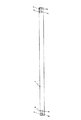
図1は、本発明の発熱体の第1の実施形態を示す正面図である。
【0058】
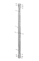
図2は、同じく背面図である。
【0059】
図3は、同じくガラス膜を除去して抵抗発熱体の配置を示す背面図である。
【0060】
図4は、同じく要部拡大断面図である。
【0061】
図において、1は絶縁基板、2は第1の抵抗発熱体、3は第2の抵抗発熱体、4は第1の導電体パターン、5は第2の導電体パターン、6は第1の端子パターン、7は第2の端子パターン、8は第1のスルーホール、9は第2のスルーホール、10はガラス膜である。
【0062】
絶縁基板1は、長さ270mm、幅10mm、厚さ0.635mmの細長い窒化アルミニウムの薄板からなる。
【0063】
第1の抵抗発熱体2は、パラジウムを55重量%含有する銀・パラジウム系合金を主成分とする導電材料を絶縁基板1の背面の中央から幾分偏った位置にスクリーン印刷され、乾燥後焼成して形成した厚膜の抵抗発熱体である。
【0064】
第2の抵抗発熱体3は、第1の抵抗発熱体2とわずかな間隙をおき、かつ第1の抵抗発熱体と中央を一致させているが、短くて平行な関係に同様材料、同様プロセスによって絶縁基板1の背面に形成されている。
【0065】
第1の導電体パターン4は、絶縁基板1の背面において、一端が第1の抵抗発熱体2の端部に接続し、他端が絶縁基板1の端部に延在している。
【0066】
第2の導電体パターン5は、絶縁基板1の背面において、一端が第2の抵抗発熱体3の端部に接続し、他端が絶縁基板1の端部に延在している。
【0067】
第1の端子パターン6は、絶縁基板1の背面の端部において、第1の導電体パターン4に接続して配設されている。
【0068】
第2の端子パターン7は、絶縁基板1の背面の端部において、第1の端子パターン6の外側に隣接する位置で、第2の導電体パターン5に接続して配設されている。
【0069】
さらに、第1および第2の端子パターン6、7は、絶縁基板1の正面にも背面のそれと正対して配設されており、両面の各端子パターン6、7は、それぞれ第1および第2のスルーホール8、9を介して相互に接続されている。
【0070】
ガラス膜10は、第1および第2の抵抗発熱体2、3を形成している絶縁基板1の背面において、各抵抗発熱体2、3の上から絶縁基板1のほぼ全体にわたって形成されている。
【0071】
また、ガラス膜10は、アルミナの中空フィラーをホウケイ酸ガラスに添加混合することによって、内部に多数の気泡を含有させた構成である。
【0072】
そうして、本実施形態の発熱体は、絶縁基板1の表面を伝熱面として用いるのに適している。
【0073】
図5は、本発明の発熱体の第2の実施形態を示す要部拡大断面図である。
【0074】
図において、図4と同一部分については同一符号を付して説明は省略する。
【0075】
本実施形態は、絶縁基板1の背面を粗面化している点で異なる。
【0076】
すなわち、絶縁基板1は、内面を粗面化した金型を用いて成形時に粗面化した粗面化部1aを背面に備えている。そして、絶縁基板1の背面の粗面化部1aに抵抗発熱体2、3および多数の気泡を含有させたガラス膜10を順次形成している。
【0077】
ガラス膜は、ホウケイ酸鉛ガラスを用いているので、断熱性が良好であるとともに、絶縁基板1の背面が粗面化されているので、多数の気泡を含有させたガラス膜10の絶縁基板への密着性は良好である。
【0078】
なお、多数の気泡を含有させたガラス膜10として、ホウケイ酸鉛ガラスにアルミナ中空フィラーを25〜35重量%含有した材料を用いて膜厚約50μmのガラス膜を形成することにより、断熱性に加えて十分な電気絶縁耐力を付与することができる。
【0079】
図6は、本発明の発熱体の第3の実施形態を示す要部拡大正面図である。
【0080】
図において、図4と同一部分については同一符号を付して説明は省略する。
【0081】
本実施形態は、絶縁基板1の伝熱面にガラス膜11を形成している点で異なる。
【0082】
すなわち、本実施形態は、絶縁基板1の伝熱面に平滑性の良好なガラス膜11を形成することにより、発熱体と被加熱体または被加熱体を搬送する搬送シートとの間の摩擦抵抗を少なくしたものである。
【0083】
窒化アルミニウムの絶縁基板1は、アルミナセラミックスの絶縁基板と比較すると、表面が平滑でなく、そのまま伝熱面として使うと、摩擦抵抗が増加する。
【0084】
そこで、本発明は、上述のように平滑なガラス膜11を絶縁基板1の伝熱面に形成して、摩擦抵抗の低減を図ったものである。
【0085】
平滑なガラス膜11を得るには、たとえば中空フィラーを添加しないか、添加量を少なくしてガラス膜を形成すればよい。
【0086】
図7は、本発明の発熱体の第4の実施形態を示す要部拡大断面図である。
【0087】
図において、図4と同一部分については同一符号を付して説明は省略する。
【0088】
本実施形態は、第1および第2の抵抗発熱体2、3の上からガラス膜12と合成樹脂膜13を重ねて形成している点で異なる。
【0089】
すなわち、ガラス膜12は、ホウケイ酸亜鉛ガラスを主成分としている関係で窒化アルミニウムの絶縁基板1との密着性が比較的良好な構成であり、第1および第2の抵抗発熱体2、3に対する保護膜としても機能する。
【0090】
合成樹脂膜13は、ポリイミド樹脂からなり、熱伝導率がガラスより小さいので、ガラス膜12とあいまって十分な断熱性を付与している。
【0091】
したがって、本実施形態においては、絶縁基板1の表面を伝熱面として用いることにより、熱効率の高い発熱体となる。
【0092】
図8は、本発明の発熱体の第5の実施形態を示す要部拡大断面図である。
【0093】
図において、図4と同一部分については同一符号を付して説明は省略する。
【0094】
本実施形態は、窒化アルミニウムの絶縁基板1の背面に形成した第1および第2の抵抗発熱体2、3の上からシリコーン樹脂膜14を絶縁基板1の背面のほぼ全体に形成した点で異なる。
【0095】
すなわち、本実施形態においては、シリコーン樹脂膜14が断熱層を形成するとともに、発熱体に局部的な応力が生じた際にクッション作用を呈するので、応力を吸収して絶縁基板1の割れを防止する。
【0096】
図9は、本発明の発熱体の第6の実施形態を示す正面図である。
【0097】
図10は、同じく背面図である。
【0098】
図11は、同じく要部拡大断面図である。
【0099】
図において、図2と同一部分については同一符号を付して説明は省略する。
【0100】
本実施形態は、抵抗発熱体2を1本備え、抵抗発熱体2を形成している側を伝熱面としている点が主として異なる。
【0101】
すなわち、抵抗発熱体2は、窒化アルミニウムの絶縁基板1の一方の面のほぼ中央に形成され、抵抗発熱体2の上からガラス膜15が絶縁基板1のほぼ全体にわたって形成され、その一方の端部は直接一方の端子パターン6に接続しているが、他端は第1の導電体パターン4およびスルーホール16を介して他方の端子パターン6に接続している。
【0102】
ガラス膜15は、ホウケイ酸ガラスを主体としてシリカのフィラーを添加していて、主として抵抗発熱体2の保護膜として機能する。
【0103】
絶縁基板1の他方の面には、抵抗発熱体2の温度を絶縁基板を介して感知する位置にサーミスタからなる温度センサ17が配設され、第3の導電体パターン18およびスルーホール19を介して第3の端子パターン20に接続している。
【0104】
また、絶縁基板1の他方の面には、シリコーン樹脂膜21が端子パターンなどを除いて絶縁基板1のほぼ全体に形成されている。
【0105】
そうして、本実施形態においては、抵抗発熱体2を形成している方の絶縁基板1の面を伝熱面として用いる場合に、絶縁基板1の非伝熱面に形成したシリコーン膜21が断熱層として作用して非伝熱面からの熱損失を低減するので、熱効率が向上するとともに、絶縁基板1に局部的な応力が作用してもシリコーン樹脂膜21がそれを吸収するので、絶縁基板1が割れにくくなる。
【0106】
また、絶縁基板1は、窒化アルミニウムから構成されているので、抵抗発熱体2から発生した熱が素早く絶縁基板1に伝導して発熱体の温度分布を均整化するので、熱定着に用いた際に定着品質を高める作用がある。
【0107】
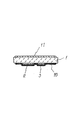
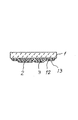
図12は、本発明の定着装置の一実施形態を示す断面図である。
【0108】
図において、22は発熱体で、図1ないし図11に示す構造複数の実施形態のいずれをも用いることができる。
【0109】
23は加圧ローラで、発熱体22と圧接関係を有しており、両者の間に被記録材24を狭圧しながら搬送することにより、被記録材24に付着しているトナー4aが発熱体22の熱によって溶融し、熱定着が行われる。なお、被記録材24と加圧ローラ23との間にポリイミド樹脂製などの無端の搬送シート25を介在させている。
【0110】
26は発熱体14の支持体である。27は定着装置本体で、以上の各構成要素を収容している。
【0111】
発熱体22は、その抵抗発熱体が搬送シート25を介して加圧ローラ23に圧接するように配置されている。
【0112】
図13は、本発明の画像形成装置の第1の実施形態としての複写機の概念図である。
【0113】
図において、30は読取装置、31は画像形成手段、32は定着装置、33は画像形成装置本体である。
【0114】
読取装置30は、原紙を光学的に読み取って画像信号を形成する。
【0115】
画像形成手段31は、画像信号に基づいて感光ドラム31a上に静電潜像を形成し、この静電潜像にトナーを付着させて反転顕像を形成し、これを紙などの被定着体に転写して画像を形成する。
【0116】
定着装置32は、図12に示した構造を有し、被記録材に付着したトナーを加熱溶融して熱定着する。
【0117】
画像形成装置本体33は、以上の各装置および手段30、31および32を収納するとともに、搬送装置、電源装置および制御装置などを備えている。
【0118】
図14は、本発明の画像形成装置の第2の実施形態としてのプリンタの概念図である。
【0119】
図において、34は画像形成手段、35は定着装置、36はプリンタ本体である。
【0120】
画像形成手段34は、レーザスキャナ34aおよび感光ドラム34bなどを含んで構成され、外部から入力された画像信号に基づいて画像を形成する。
【0121】
定着装置35は、図12に示す構造を備えている。
【0122】
プリンタ本体36は、画像形成手段34および定着装置35を収納するとともに、搬送装置、電源装置および制御装置などを備えている。
【0123】
【発明の効果】
請求項1ないし6の各発明によれば、窒化アルミニウムからなる細長い絶縁基板の一方の面に細長い抵抗発熱体を形成し、絶縁基板のいずれか一方の面を伝熱面とする場合に、他方の面からの熱損失を新規な構成の断熱層を配設したことによって、通常のガラスを断熱層として用いた従来の発熱体より熱損失を低減し、したがって熱効率の高い発熱体を提供することができる。
【0124】
請求項1の発明によれば、加えて金属酸化物からなる中空フィラーを添加して多数の気泡を含有させた多数の気泡を含有するガラス膜を抵抗発熱体の上から絶縁基板の一方の面に形成したことにより、抵抗発熱体を形成していない絶縁基板の他方の面を伝熱面とする場合に、非伝熱面からの熱損失を少なくするとともに、上記ガラス膜および絶縁基板の協働によって抵抗発熱体を気密に包囲して保護できるので、大気との接触などによって抵抗値が変化するような不都合が生じにくい発熱体を提供することができる。
【0125】
請求項2の発明によれば、加えて抵抗発熱体を形成しない方の面に金属酸化物からなる中空フィラーを添加して多数の気泡を含有させた多数の気泡を含有するガラス膜を形成したことにより、抵抗発熱体を形成した方の面を伝熱面とする場合に、非伝熱面からの熱損失を少なくした発熱体を提供することができる。
【0126】
請求項3の発明によれば、加えて絶縁基板の多数の気泡を含有させたガラス膜が形成されている面が粗面化されていることにより、ガラス膜の絶縁基板に対する密着性が良好になり、絶縁基板に対する密着性が相対的に良好でないが断熱性に優れるガラスを用いることも可能な発熱体を提供することができる。
【0127】
請求項4の発明によれば、加えて絶縁基板に抵抗発熱体の上から柔軟性、耐熱性および断熱性を備えた合成樹脂膜を形成したことにより、抵抗発熱体を形成していない絶縁基板の面を伝熱面にする場合に、非伝熱面となる抵抗発熱体を形成している面からの熱損失を低減するばかりか、絶縁基板に局部的な応力が作用しても合成樹脂膜がクッション作用をするので、絶縁基板の割れを防止するのに効果的な発熱体を提供することができる。
【0128】
請求項5の発明によれば、加えて絶縁基板の抵抗発熱体を形成してない方の面に柔軟性、耐熱性および断熱性を備えた合成樹脂膜を形成したことにより、抵抗発熱体を形成している方の絶縁基板の面を伝熱面とする場合に、非伝熱面である抵抗発熱体を形成してない面からの熱損失を低減するばかりか、絶縁基板に局部的な応力が作用しても合成樹脂膜がクッションの作用をするので、絶縁基板の我を防止するのに効果的な発熱体を提供することができる。
【0129】
請求項6の発明によれば、加えて抵抗発熱体の上からホウケイ酸系のガラスまたはホウケイ酸亜鉛系のガラスを主成分とするガラス膜とガラス膜の上に形成された合成樹脂膜とを備えることにとにより、断熱性に優れて熱効率の高い発熱体を提供することができる。
【0130】
請求項7の発明によれば、請求項1ないし6の効果を有する定着装置を提供することができる。
【0131】
請求項8の発明によれば、請求項1ないし6の効果を有する画像形成装置を提供することができる。
【図面の簡単な説明】
【図1】本発明の発熱体の第1の実施形態を示す正面図
【図2】同じく背面図
【図3】同じくガラス膜を除去して抵抗発熱体の配置を示す背面図
【図4】同じく要部拡大断面図
【図5】本発明の発熱体の第2の実施形態を示す要部拡大断面図
【図6】本発明の発熱体の第3の実施形態を示す要部拡大断面図
【図7】本発明の発熱体の第4の実施形態を示す要部拡大断面図
【図8】本発明の発熱体の第5の実施形態を示す要部拡大断面図
【図9】本発明の発熱体の第6の実施形態を示す正面図
【図10】同じく背面図
【図11】同じく要部拡大断面図
【図12】本発明の定着装置の一実施形態を示す概念図
【図13】本発明の画像形成装置の第1の実施形態としての複写機の概念図
【図14】本発明の画像形成装置の第2の実施形態としてのプリンタの概念図
【符号の説明】
1…絶縁基板
2…第1の抵抗発熱体
3…第2の抵抗発熱体
10…ガラス膜[0001]
BACKGROUND OF THE INVENTION
The present invention relates to a heating element, a fixing device using the same, and an image forming apparatus.
[0002]
[Prior art]
In an image forming apparatus such as a copying machine, a printer, or a facsimile, a heating element for heat fixing a developer such as toner is disclosed in JP-A-6-324586. This heating element is obtained by forming a long and thin resistance heating element on a long and thin insulating substrate made of alumina ceramics.
[0003]
Thus, since the heat generating element has a small heat capacity, when the power supply voltage is applied, the action part of the heat generating element contributing to the thermal fixing of the developer instantly increases in temperature to the required temperature. Therefore, when this heating element is used in an image forming apparatus or the like, there are advantages that the wait time can be shortened, that no standby power is consumed, and that the temperature inside the apparatus of the image forming apparatus can be suppressed.
[0004]
On the other hand, since a heating element for heat fixing is operated by applying a relatively high voltage, high voltage resistance is required. In addition, the heating element is required to have high wear resistance and low frictional resistance because a conveying sheet made of polyimide resin or the like is in sliding contact with the surface of the heating element. In order to meet these requirements, the resistance heating element and the insulating substrate on which the heating element is formed are surrounded by a glassy protective film.
[0005]
Further, in order to increase the heat generation amount of the resistance heating element in order to meet the demand for high speed image forming apparatus, aluminum nitride is used for the insulating substrate, and the surface opposite to the surface on which the resistance heating element is formed is fixed. Japanese Patent Application Laid-Open No. 10-133501 discloses a heating element that is directly or indirectly brought into contact with the heat generating element. Aluminum nitride has a thermal conductivity higher than that of the protective film formed on the insulating substrate so as to cover the heating element. Therefore, in the case of a heating element using an aluminum nitride insulating substrate, it is transmitted to the heated object via the insulating substrate. Since the heat efficiency is better when heated, and the heat loss generated from the insulating substrate surface where the resistance heating element is formed, i.e., the non-heat transfer surface, increases, so a glass layer is formed as a heat insulation layer on the resistance heating element. Thus, it is described in the above publication that the reduction in thermal efficiency due to heat loss is improved.
[0006]
[Problems to be solved by the invention]
However, in the heating element using the above-described conventional aluminum nitride as the insulating substrate, the heat conductivity is 2 to 3 × 10 6 as the heat insulating layer.-3Since normal glass of about (cal / cm sec K) is used, the thermal conductivity of aluminum nitride is 5 × 10.-1Compared with (cal / cm sec K), although heat conduction is extremely small, heat insulation that is still sufficiently satisfactory has not been obtained.
[0007]
In addition, it is suggested that the above-described conventional technology uses a heat insulating insulating resin such as PI, PFA, PTFE, etc. as a heat insulating layer, and a synthetic resin generally has a lower heat conductivity than glass, and thus is good in terms of heat insulating properties. However, there are the following problems.
[0008]
In other words, as the recording material supplied to the image forming apparatus, paper of various sizes and thicknesses from plain paper to small thick paper such as postcards may be used. Since it is attached and fixed while pressing from above, when a thick material is supplied as the recording material, local stress acts on the part of the heating element that contacts the recording material. Fragile.
[0009]
The present invention further reduces the heat loss generated from the non-heat transfer surface when aluminum nitride is used as an insulating substrate, compared with the case where normal glass is used as a heat insulating layer, and even if a thick recording material is used, the insulating substrate is used. An object of the present invention is to provide a heating element that is difficult to break, a fixing device using the same, and an image forming apparatus.
[0010]
[Means for achieving the object]
The heating element of the invention of claim 1 is an elongated insulating substrate made of aluminum nitride; an elongated resistance heating element formed on one surface of the insulating substrate along the longitudinal direction thereof; Formed on one sideAdd a hollow filler made of metal oxideContains many bubblesLetAnd a glass film.
[0011]
In the present invention and each of the following inventions, the definitions and technical meanings of terms are as follows unless otherwise specified.
[0012]
(Insulating substrate)
The insulating substrate is made of aluminum nitride at portions where a resistance heating element and a conductor pattern and a terminal pattern associated with the resistance heating element are formed. In addition, what was formed in the thin plate shape using a doctor blade method etc. can be used for an insulated substrate.
[0013]
In addition, the shape of the insulating substrate is not particularly limited as long as it is long and thin as much as possible.
[0014]
(About resistance heating elements)
The resistance heating element is not particularly limited in material, shape, dimensions, and manufacturing method, but the most suitable is a thick film resistance formed by printing and baking a conductive paste mainly composed of a silver / palladium alloy by a screen printing method. It is a heating element. According to this thick film resistance heating element, the resistance value of the resistance heating element is required for a long heating element capable of satisfactorily fixing toner on a sheet mainly used for A4 and A3 sizes. It is easy to design so as to obtain a high temperature.
[0015]
Further, the resistance heating element is not limited to one, and a plurality of resistance heating elements may be formed in parallel. Further, a plurality of resistance heating elements extending substantially in parallel may be connected in series with a conductor pattern or a resistance heating element material so as to meander in a bent state.
[0016]
(About glass film)
The glass film surrounds the resistance heating element in cooperation with the insulating substrate to electrically insulate it, and covers the resistance heating element and the surface of the insulating substrate on which the resistance heating element is disposed to insulate it. Used for. In the present invention, in the glass filmBy means described belowMany bubblesTheContainsLetNoOf the present inventionIt is a feature.
[0017]
That is,Contains many bubblesforAdd hollow fillers made of metal oxide to glassAnd thisRealizationHaveThe
[0018]
As the glass type, borosilicate glass, lead borosilicate glass, zinc borosilicate glass, or the like can be used. Note that borosilicate glass and zinc borosilicate glass are relatively excellent in adhesion of aluminum nitride to an insulating substrate. In contrast, lead borosilicate glass is relatively superior in heat insulation.
[0019]
As the hollow filler, one made of alumina or silica can be used.
[0020]
In the glass filmAdd a hollow filler made of metal oxideContains many bubblesLetAs a result, the thermal conductivity can be reduced to a fraction or a fraction of that of a single glass.
[0021]
(About other configurations)
In order to keep the temperature of the resistance heating element constant, a temperature sensor such as a thermistor can be disposed at a position where the resistance heating element receives heat. Then, the temperature sensor is connected to the temperature control circuit.
[0022]
Then, the temperature control circuit controls the energization of the resistance heating element so that the heat generation amount becomes constant. In the present invention, the temperature sensor is disposed as close to the resistance heating element as possible on the surface of the insulating substrate on which the resistance heating element is formed. Can be prevented.
[0023]
Further, if necessary, an overheat prevention means such as a thermal fuse may be provided.
[0024]
Furthermore, the heating element of the present invention is suitable for heat fixing, but is not limited to this, and is applicable to all uses.
[0025]
(Operation of the present invention)
The heating element of the present invention is effective when the other surface of the insulating substrate having a resistance heating element formed on one surface is used as the heat transfer surface. That is, on the surface on which the resistance heating element that becomes the non-heat transfer surface is formed,Add a hollow filler made of metal oxideContains many bubblesLetSince the glass film is formed, its thermal conductivity is much smaller than that of a single glass, and therefore heat loss generated from the non-heat transfer surface is greatly reduced.
[0026]
Therefore, the heating element of the present invention exhibits higher thermal efficiency than the heating element provided with the conventional glass heat insulating layer.
[0027]
Also, the resistance heating elementAdd a hollow filler made of metal oxideContains many bubblesLetSince the glass film and the insulating substrate are hermetically enclosed by the cooperation of the glass film and the insulating substrate, the protection is better than that of the conventional synthetic resin layer.That is, the glass film serves as both a heat insulating layer and a protective layer.
[0028]
The heating element of the invention of
[0029]
The present invention is a heating element suitable when one surface of the insulating substrate forming the resistance heating element is a heat transfer surface. Therefore, on the other side of the insulating substrateAdd a hollow filler made of metal oxideContains many bubblesLetBy forming the glass film, heat loss from the non-heat transfer surface can be remarkably reduced.
[0030]
Moreover, in this invention, even if it is a case where one surface which forms the resistance heating element is used as a heat transfer surface, the following useful effects are obtained. That is, an aluminum nitride insulating substrateAs a heat transfer surfaceBy using it, there is some variation in the heat generation distribution in the longitudinal direction of the resistance heating element.AhEven so, the generated heat is first transferred to the insulating substrate having a high thermal conductivity, and as a result, the temperature is leveled in the longitudinal direction of the heating element and then transferred to the developer of the recording material. The temperature distribution becomes uniform and the quality of heat fixing is improved.
[0031]
The heating element of the invention of
[0032]
The insulating substrate of aluminum nitride does not have good adhesion to glass compared to alumina ceramics.
[0033]
Therefore, in the present invention, by previously roughening the surface of the insulating substrate,Contained many bubblesIt improves the adhesion with the glass film.
[0034]
Any method of roughening the surface of the insulating substrate of aluminum nitride may be used. For example, the surface of the insulating substrate may be roughened by using a die whose inner surface is roughened or by mechanical processing such as sand blasting or buffing. be able to.
[0035]
The heating element of the invention of claim 4 is an elongated insulating substrate made of aluminum nitride; an elongated resistance heating element formed on one surface of the insulating substrate along the longitudinal direction thereof; And a synthetic resin film having flexibility, heat resistance and heat insulation formed on one surface.
[0036]
“Having flexibility” means that there is flexibility enough to appropriately absorb the stress applied to the insulating substrate during thermal fixing. Further, “having heat resistance” only needs to be enough to withstand the temperature of the usage environment of the heating element and its own heat generation. Furthermore, “having heat insulation” may be any degree as long as the thermal conductivity is smaller than that of normal glass. And as a synthetic resin provided with the above three conditions, silicone resin etc. correspond, for example.
[0037]
Thus, in the present invention, the resistance heating element is formed when the recording material is heated by using the opposite surface of the insulating substrate made of aluminum nitride as the heat transfer surface. By heat-insulating the non-heat transfer surface with the synthetic resin film, heat loss can be reduced and the heat efficiency of the heating element can be increased. In addition, since the synthetic resin film has flexibility, even if stress is locally applied to the insulating substrate due to the thick recording material, the synthetic resin film portion Since the stress is absorbed moderately, the insulating substrate is less cracked.
[0038]
The heating element of the invention of claim 5 is an elongated insulating substrate made of aluminum nitride; an elongated resistance heating element formed on one surface of the insulating substrate along the longitudinal direction; and a flexible material formed on the other surface And a synthetic resin film having heat resistance, heat resistance, and heat insulation.
[0039]
The present invention defines a structure suitable for transferring heat to a recording material or the like using the surface of the insulating substrate on which the resistance heating element is formed as a heat transfer surface.
[0040]
The function and effect of the synthetic resin film are basically the same as those of the fourth aspect.
[0041]
The heating element of the invention of claim 6 is an elongated insulating substrate made of aluminum nitride; an elongated resistance heating element formed on one surface of the insulating substrate along the longitudinal direction thereof; A glass film mainly composed of borosilicate glass or zinc borosilicate glass formed on one surface; and a synthetic resin film formed on the glass film. Yes.
[0042]
In the present invention, the glass film includes borosilicate glass, borosilicateAsiaLead glass or glass obtained by adding an appropriate amount of a metal oxide filler such as powder of alumina or silica, hollow alumina, silica or the like to these glasses can be used.
[0043]
As the synthetic resin film, a silicone-based synthetic resin, a polyimide-based synthetic resin, a fluorine-based synthetic resin, or the like can be used.
[0044]
Thus, a glass film mainly composed of borosilicate glass or zinc borosilicate glass has a relatively good adhesion to an insulating substrate of aluminum nitride, and thus is excellent as a protective film for a resistance heating element. Yes.
[0045]
However, since the above glass has a relatively high thermal conductivity compared to lead borosilicate glass, in the present invention, a synthetic resin film is further formed on the glass film to provide the required heat insulation. It has gained.
[0046]
Therefore, in the present invention, the resistance heating element is sufficiently protected by a glass film excellent as a protective film, and the required heat insulation is provided by the synthetic resin film and the glass film formed on the glass film. Heat transfer with high thermal efficiency can be performed on the recording material or the like through the high thermal conductivity of the substrate.
[0047]
Further, when a silicone resin is used as the synthetic resin, since it is further provided with flexibility, the same effect as that of the fourth aspect can be obtained and the crack of the insulating substrate is reduced.
[0048]
According to a seventh aspect of the present invention, there is provided a fixing device comprising: the heating element according to any one of the first to sixth aspects; and a pressure roller disposed in pressure contact with the heat transfer surface of the heating element. It is characterized by having.
[0049]
In the present invention, the heat transfer surface of the heating element according to claims 1 to 6 is used in pressure contact with the pressure roller, but the pressure roller may be in direct contact with the pressure roller, but indirectly through a conveying sheet or the like. You may press-contact to. Note that the transport sheet may be endless or roll-shaped.
[0050]
Thus, in the present invention, the heat loss from the non-heat transfer surface of the insulating substrate made of aluminum nitride can be reduced to increase the thermal efficiency of the heating element, and when using a silicone resin as a heat insulating means, The flexibility absorbs the stress applied to the insulating substrate and reduces the cracking of the insulating substrate.
[0051]
An image forming apparatus according to
[0052]
Examples of the image forming apparatus include an electrophotographic copying machine, a printer, and a facsimile.
[0053]
Examples of the recording material include a transfer material sheet, printing paper, an electrofax sheet, and an electrostatic recording sheet.
[0054]
The “indirect method” is a method for forming an image by transfer.
[0055]
Thus, in the present invention, it is possible to provide an image forming apparatus including the heating element having the configuration of claims 1 to 6 to increase the thermal efficiency of the heating element and further reduce cracking due to stress of the insulating substrate. .
[0056]
DETAILED DESCRIPTION OF THE INVENTION
Hereinafter, embodiments of the present invention will be described with reference to the drawings.
[0057]
FIG. 1 is a front view showing a first embodiment of a heating element of the present invention.
[0058]
FIG. 2 is also a rear view.
[0059]
FIG. 3 is a rear view showing the arrangement of the resistance heating elements by removing the glass film.
[0060]
FIG. 4 is an enlarged cross-sectional view of the main part.
[0061]
In the figure, 1 is an insulating substrate, 2 is a first resistance heating element, 3 is a second resistance heating element, 4 is a first conductor pattern, 5 is a second conductor pattern, and 6 is a first terminal. The pattern, 7 is a second terminal pattern, 8 is a first through hole, 9 is a second through hole, and 10 is a glass film.
[0062]
The insulating substrate 1 is made of an elongated aluminum nitride thin plate having a length of 270 mm, a width of 10 mm, and a thickness of 0.635 mm.
[0063]
The first
[0064]
The second
[0065]
The first conductor pattern 4 has one end connected to the end of the first
[0066]
The second conductor pattern 5 has one end connected to the end of the second
[0067]
The first terminal pattern 6 is connected to the first conductor pattern 4 at the end of the back surface of the insulating substrate 1.
[0068]
The second terminal pattern 7 is connected to the second conductor pattern 5 at a position adjacent to the outside of the first terminal pattern 6 at the end of the back surface of the insulating substrate 1.
[0069]
Further, the first and second terminal patterns 6 and 7 are disposed on the front surface of the insulating substrate 1 so as to face the back surface of the insulating substrate 1, and the terminal patterns 6 and 7 on both sides are respectively the first and second terminals. Are connected to each other through through
[0070]
The
[0071]
Further, the
[0072]
Thus, the heating element of the present embodiment is suitable for using the surface of the insulating substrate 1 as a heat transfer surface.
[0073]
FIG. 5 is an enlarged cross-sectional view of a main part showing a second embodiment of the heating element of the present invention.
[0074]
In the figure, the same parts as those in FIG.
[0075]
This embodiment is different in that the back surface of the insulating substrate 1 is roughened.
[0076]
In other words, the insulating substrate 1 includes a roughened portion 1a roughened at the time of molding using a mold having a roughened inner surface on the back surface. And the
[0077]
Since the glass film uses lead borosilicate glass, the heat insulation is good and the back surface of the insulating substrate 1 is roughened.Contained many bubblesThe adhesion of the
[0078]
In addition,Contained many
[0079]
FIG. 6 is an enlarged front view of an essential part showing a third embodiment of the heating element of the present invention.
[0080]
In the figure, the same parts as those in FIG.
[0081]
This embodiment is different in that a
[0082]
That is, in this embodiment, by forming the
[0083]
The insulating substrate 1 made of aluminum nitride has a non-smooth surface compared to an insulating substrate made of alumina ceramics, and if used as a heat transfer surface as it is, the frictional resistance increases.
[0084]
Therefore, in the present invention, the
[0085]
To obtain a
[0086]
FIG. 7 is an enlarged cross-sectional view of a main part showing a fourth embodiment of the heating element of the present invention.
[0087]
In the figure, the same parts as those in FIG.
[0088]
This embodiment is different in that the
[0089]
That is, the
[0090]
The
[0091]
Therefore, in this embodiment, it becomes a heat generating body with high thermal efficiency by using the surface of the insulating substrate 1 as a heat transfer surface.
[0092]
FIG. 8 is an enlarged cross-sectional view of a main part showing a fifth embodiment of the heating element of the present invention.
[0093]
In the figure, the same parts as those in FIG.
[0094]
This embodiment is different in that a
[0095]
That is, in the present embodiment, the
[0096]
FIG. 9 is a front view showing a sixth embodiment of the heating element of the present invention.
[0097]
FIG. 10 is also a rear view.
[0098]
FIG. 11 is also an enlarged cross-sectional view of the main part.
[0099]
In the figure, the same parts as those in FIG.
[0100]
This embodiment mainly differs in that one
[0101]
That is, the
[0102]
The
[0103]
On the other surface of the insulating substrate 1, a
[0104]
On the other surface of the insulating substrate 1, a
[0105]
Thus, in the present embodiment, when the surface of the insulating substrate 1 on which the
[0106]
Further, since the insulating substrate 1 is made of aluminum nitride, the heat generated from the
[0107]
FIG. 12 is a cross-sectional view showing an embodiment of the fixing device of the present invention.
[0108]
In the figure,
[0109]
A
[0110]
[0111]
The
[0112]
FIG. 13 is a conceptual diagram of a copying machine as a first embodiment of the image forming apparatus of the present invention.
[0113]
In the figure, 30 is a reading device, 31 is an image forming means, 32 is a fixing device, and 33 is a main body of the image forming device.
[0114]
The
[0115]
The
[0116]
The fixing
[0117]
The image forming apparatus main body 33 houses each of the above devices and means 30, 31 and 32, and includes a transport device, a power supply device, a control device, and the like.
[0118]
FIG. 14 is a conceptual diagram of a printer as a second embodiment of the image forming apparatus of the present invention.
[0119]
In the figure, 34 is an image forming means, 35 is a fixing device, and 36 is a printer body.
[0120]
The
[0121]
The fixing
[0122]
The printer
[0123]
【The invention's effect】
According to each of the first to sixth aspects of the present invention, when the elongated resistance heating element is formed on one surface of the elongated insulating substrate made of aluminum nitride and any one surface of the insulating substrate is used as the heat transfer surface, the other By disposing a heat insulating layer with a novel structure, the heat loss is reduced compared to the conventional heat generating element using ordinary glass as the heat insulating layer, and thus a heat generating element with high heat efficiency is provided. Can do.
[0124]
According to the invention of claim 1, in additionAdd a hollow filler made of metal oxideContains many bubblesLetBy forming a glass film containing a large number of bubbles on one surface of the insulating substrate from above the resistance heating element, when the other surface of the insulating substrate not forming the resistance heating element is a heat transfer surface, Less heat loss from non-heat transfer surfaceIn addition, since the resistance heating element can be hermetically surrounded and protected by the cooperation of the glass film and the insulating substrate, there is little inconvenience that the resistance value changes due to contact with the atmosphere.A heating element can be provided.
[0125]
According to the invention of
[0126]
According to the invention of
[0127]
According to the invention of claim 4, in addition, an insulating substrate in which no resistance heating element is formed by forming a synthetic resin film having flexibility, heat resistance and heat insulation from above the resistance heating element on the insulating substrate. When making the heat transfer surface into a heat transfer surface, not only the heat loss from the surface on which the resistance heating element that forms the non-heat transfer surface is reduced, but also the synthetic resin even if local stress acts on the insulating substrate Since the film acts as a cushion, it is possible to provide an effective heating element for preventing the insulating substrate from cracking.
[0128]
According to the invention of claim 5, in addition, by forming the synthetic resin film having flexibility, heat resistance and heat insulation on the surface of the insulating substrate where the resistance heating element is not formed, the resistance heating element is obtained. When the surface of the insulating substrate that is formed is used as the heat transfer surface, not only the heat loss from the surface that does not form the resistance heating element, which is a non-heat transfer surface, is reduced, but also locally on the insulating substrate. Since the synthetic resin film acts as a cushion even if stress acts, it is possible to provide an effective heating element for preventing the insulating substrate from being damaged.
[0129]
According to the invention of claim 6, in addition, a glass film mainly composed of borosilicate glass or zinc borosilicate glass and a synthetic resin film formed on the glass film are formed on the resistance heating element. By providing it, it is possible to provide a heat generator that has excellent heat insulation and high thermal efficiency.
[0130]
According to the seventh aspect of the present invention, a fixing device having the effects of the first to sixth aspects can be provided.
[0131]
According to the invention of
[Brief description of the drawings]
FIG. 1 is a front view showing a first embodiment of a heating element of the present invention.
[Figure 2] Rear view
FIG. 3 is a rear view showing the arrangement of resistance heating elements with the glass film removed.
FIG. 4 is an enlarged cross-sectional view of the same main part
FIG. 5 is an enlarged cross-sectional view of a main part showing a second embodiment of the heating element of the present invention.
FIG. 6 is an enlarged cross-sectional view of a main part showing a third embodiment of the heating element of the present invention.
FIG. 7 is an enlarged cross-sectional view of a main part showing a fourth embodiment of a heating element of the present invention.
FIG. 8 is an enlarged cross-sectional view of a main part showing a fifth embodiment of a heating element of the present invention.
FIG. 9 is a front view showing a sixth embodiment of the heating element of the present invention.
FIG. 10 is also a rear view.
FIG. 11 is an enlarged sectional view of the main part of the same
FIG. 12 is a conceptual diagram showing an embodiment of a fixing device of the present invention.
FIG. 13 is a conceptual diagram of a copier as a first embodiment of an image forming apparatus according to the present invention.
FIG. 14 is a conceptual diagram of a printer as a second embodiment of the image forming apparatus according to the invention.
[Explanation of symbols]
1 ... Insulating substrate
2 ... 1st resistance heating element
3 ... Second resistance heating element
10 ... Glass film
Claims (8)
絶縁基板の一方の面にその長手方向に沿って形成された細長い抵抗発熱体と;
抵抗発熱体の上から絶縁基板の一方の面に形成された金属酸化物からなる中空フィラーを添加して多数の気泡を含有させたガラス膜と;
を具備していることを特徴とする発熱体。An elongated insulating substrate made of aluminum nitride;
An elongated resistance heating element formed on one side of the insulating substrate along its longitudinal direction;
A glass film containing a large number of bubbles by adding a hollow filler made of a metal oxide formed on one surface of the insulating substrate from above the resistance heating element;
A heating element comprising:
絶縁基板の一方の面にその長手方向に沿って形成された細長い抵抗発熱体と;
絶縁基板の他方の面に形成された金属酸化物からなる中空フィラーを添加して多数の気泡を含有させたガラス膜と;
を具備していることを特徴とする発熱体。An elongated insulating substrate made of aluminum nitride;
An elongated resistance heating element formed on one side of the insulating substrate along its longitudinal direction;
A glass film containing a large number of bubbles by adding a hollow filler made of a metal oxide formed on the other surface of the insulating substrate;
A heating element comprising:
絶縁基板の一方の面にその長手方向に沿って形成された細長い抵抗発熱体と;抵抗発熱体の上から絶縁基板の一方の面に形成されている柔軟性、耐熱性および断熱性を備えた合成樹脂膜と;
を具備していることを特徴とする発熱体。An elongated insulating substrate made of aluminum nitride;
An elongated resistance heating element formed on one surface of the insulating substrate along the longitudinal direction thereof; provided with flexibility, heat resistance and heat insulation formed on one surface of the insulating substrate from above the resistance heating element With a synthetic resin film;
A heating element comprising:
絶縁基板の一方の面にその長手方向に沿って形成された細長い抵抗発熱体と;
他方の面に形成されている柔軟性、耐熱性および断熱性を備えた合成樹脂膜と;
を具備していることを特徴とする発熱体。An elongate insulating substrate Do that aluminum nitride;
An elongated resistance heating element formed on one side of the insulating substrate along its longitudinal direction;
A synthetic resin film having flexibility, heat resistance and heat insulation formed on the other surface;
A heating element comprising:
絶縁基板の一方の面にその長手方向に沿って形成された細長い抵抗発熱体と;抵抗発熱体の上から絶縁基板の一方の面に形成されたホウケイ酸系のガラスまたはホウケイ酸亜鉛系のガラスを主成分とするガラス膜と;
ガラス膜の上に形成された合成樹脂膜と;
を具備していることを特徴とする発熱体。An elongated insulating substrate made of aluminum nitride;
An elongated resistance heating element formed on one surface of the insulating substrate along the longitudinal direction thereof; borosilicate glass or zinc borosilicate glass formed on one surface of the insulating substrate from above the resistance heating element; A glass film mainly composed of
A synthetic resin film formed on a glass film;
A heating element comprising:
発熱体の伝熱面と圧接関係を有して配設された加圧ローラと;
を具備していることを特徴とする定着装置。A heating element according to any one of claims 1 to 6;
A pressure roller disposed in pressure contact with the heat transfer surface of the heating element;
A fixing device.
画像情報を熱定着する請求項7記載の定着装置と;
を具備していることを特徴とする画像形成装置。Image forming process means for forming image information on a recording material using a heat-fixable developer by an indirect method or a direct method;
The fixing device according to claim 7, wherein the image information is heat-fixed;
An image forming apparatus comprising:
Priority Applications (1)
| Application Number | Priority Date | Filing Date | Title |
|---|---|---|---|
| JP16970798A JP3945552B2 (en) | 1998-06-17 | 1998-06-17 | Heating element, fixing device and image forming apparatus |
Applications Claiming Priority (1)
| Application Number | Priority Date | Filing Date | Title |
|---|---|---|---|
| JP16970798A JP3945552B2 (en) | 1998-06-17 | 1998-06-17 | Heating element, fixing device and image forming apparatus |
Publications (2)
| Publication Number | Publication Date |
|---|---|
| JP2000012191A JP2000012191A (en) | 2000-01-14 |
| JP3945552B2 true JP3945552B2 (en) | 2007-07-18 |
Family
ID=15891388
Family Applications (1)
| Application Number | Title | Priority Date | Filing Date |
|---|---|---|---|
| JP16970798A Expired - Fee Related JP3945552B2 (en) | 1998-06-17 | 1998-06-17 | Heating element, fixing device and image forming apparatus |
Country Status (1)
| Country | Link |
|---|---|
| JP (1) | JP3945552B2 (en) |
Families Citing this family (1)
| Publication number | Priority date | Publication date | Assignee | Title |
|---|---|---|---|---|
| DE102015119763A1 (en) | 2015-11-16 | 2017-05-18 | Heraeus Quarzglas Gmbh & Co. Kg | infrared Heaters |
-
1998
- 1998-06-17 JP JP16970798A patent/JP3945552B2/en not_active Expired - Fee Related
Also Published As
| Publication number | Publication date |
|---|---|
| JP2000012191A (en) | 2000-01-14 |
Similar Documents
| Publication | Publication Date | Title |
|---|---|---|
| JP4640775B2 (en) | Heat fixing device and image forming apparatus | |
| JP2002015839A (en) | Heating element, heating device, and image-forming device | |
| JP2007232819A (en) | Fixing heater, heating device, image forming apparatus | |
| US11640130B2 (en) | Heating unit, fixing unit, and image forming apparatus for heat generation performance and miniaturization | |
| JP4837192B2 (en) | Heater and fixing device having the heater | |
| JP3945552B2 (en) | Heating element, fixing device and image forming apparatus | |
| JP2011096464A (en) | Ceramic heater, heating device, and image forming apparatus | |
| JP2011091006A (en) | Ceramic heater, heating device, and image forming device | |
| JP2009224209A (en) | Plate heater, heater unit, heating device, and image forming device | |
| JP5042525B2 (en) | Heater, heating device, image forming apparatus | |
| JP2001223068A (en) | Heating body, method of manufacturing heating body, image heating apparatus, and image forming apparatus | |
| JP2008166096A (en) | Flat heater, fixing device, image processing device | |
| JP2000012196A (en) | Heating element, fixing device, and image forming device | |
| JP2009042417A (en) | Plate heater, heating device, image forming device | |
| JP2009059539A (en) | Plate heater, heating device, image forming device | |
| JP2008040097A (en) | Heater, heating device, image forming apparatus | |
| JP2000268941A (en) | Heating element, fixing device, and image forming device | |
| JP3924831B2 (en) | Ceramic heater and heat fixing device | |
| JPH08152795A (en) | Fixing heater, fixing device, and image forming apparatus | |
| JPH11282290A (en) | Fixing heater, fixing device, and image forming device | |
| JP4948898B2 (en) | Heater, heating device, image forming apparatus | |
| JPH11174875A (en) | Heating and fixing device | |
| JPH10154571A (en) | Heating body, method of manufacturing heating body, heating apparatus, and image forming apparatus | |
| JP2000150113A (en) | Heating element, fixing device, and image forming device | |
| JP2001244051A (en) | Plate-shaped heater, fixing device, and image forming apparatus |
Legal Events
| Date | Code | Title | Description |
|---|---|---|---|
| A621 | Written request for application examination |
Free format text: JAPANESE INTERMEDIATE CODE: A621 Effective date: 20050615 |
|
| A711 | Notification of change in applicant |
Free format text: JAPANESE INTERMEDIATE CODE: A711 Effective date: 20051118 |
|
| A131 | Notification of reasons for refusal |
Free format text: JAPANESE INTERMEDIATE CODE: A131 Effective date: 20061212 |
|
| A521 | Written amendment |
Free format text: JAPANESE INTERMEDIATE CODE: A523 Effective date: 20070213 |
|
| TRDD | Decision of grant or rejection written | ||
| A01 | Written decision to grant a patent or to grant a registration (utility model) |
Free format text: JAPANESE INTERMEDIATE CODE: A01 Effective date: 20070327 |
|
| A61 | First payment of annual fees (during grant procedure) |
Free format text: JAPANESE INTERMEDIATE CODE: A61 Effective date: 20070403 |
|
| R150 | Certificate of patent or registration of utility model |
Free format text: JAPANESE INTERMEDIATE CODE: R150 |
|
| FPAY | Renewal fee payment (event date is renewal date of database) |
Free format text: PAYMENT UNTIL: 20100420 Year of fee payment: 3 |
|
| FPAY | Renewal fee payment (event date is renewal date of database) |
Free format text: PAYMENT UNTIL: 20110420 Year of fee payment: 4 |
|
| LAPS | Cancellation because of no payment of annual fees |