JP3941088B2 - Chemical injection device - Google Patents
Chemical injection device Download PDFInfo
- Publication number
- JP3941088B2 JP3941088B2 JP26565099A JP26565099A JP3941088B2 JP 3941088 B2 JP3941088 B2 JP 3941088B2 JP 26565099 A JP26565099 A JP 26565099A JP 26565099 A JP26565099 A JP 26565099A JP 3941088 B2 JP3941088 B2 JP 3941088B2
- Authority
- JP
- Japan
- Prior art keywords
- gasket
- hook
- connecting member
- injection device
- chemical
- Prior art date
- Legal status (The legal status is an assumption and is not a legal conclusion. Google has not performed a legal analysis and makes no representation as to the accuracy of the status listed.)
- Expired - Fee Related
Links
Images


Classifications
-
- A—HUMAN NECESSITIES
- A61—MEDICAL OR VETERINARY SCIENCE; HYGIENE
- A61M—DEVICES FOR INTRODUCING MEDIA INTO, OR ONTO, THE BODY; DEVICES FOR TRANSDUCING BODY MEDIA OR FOR TAKING MEDIA FROM THE BODY; DEVICES FOR PRODUCING OR ENDING SLEEP OR STUPOR
- A61M5/00—Devices for bringing media into the body in a subcutaneous, intra-vascular or intramuscular way; Accessories therefor, e.g. filling or cleaning devices, arm-rests
- A61M5/14—Infusion devices, e.g. infusing by gravity; Blood infusion; Accessories therefor
- A61M5/142—Pressure infusion, e.g. using pumps
- A61M5/145—Pressure infusion, e.g. using pumps using pressurised reservoirs, e.g. pressurised by means of pistons
- A61M5/1452—Pressure infusion, e.g. using pumps using pressurised reservoirs, e.g. pressurised by means of pistons pressurised by means of pistons
- A61M5/1454—Pressure infusion, e.g. using pumps using pressurised reservoirs, e.g. pressurised by means of pistons pressurised by means of pistons spring-actuated, e.g. by a clockwork
-
- A—HUMAN NECESSITIES
- A61—MEDICAL OR VETERINARY SCIENCE; HYGIENE
- A61M—DEVICES FOR INTRODUCING MEDIA INTO, OR ONTO, THE BODY; DEVICES FOR TRANSDUCING BODY MEDIA OR FOR TAKING MEDIA FROM THE BODY; DEVICES FOR PRODUCING OR ENDING SLEEP OR STUPOR
- A61M5/00—Devices for bringing media into the body in a subcutaneous, intra-vascular or intramuscular way; Accessories therefor, e.g. filling or cleaning devices, arm-rests
- A61M5/178—Syringes
- A61M5/31—Details
- A61M5/315—Pistons; Piston-rods; Guiding, blocking or restricting the movement of the rod or piston; Appliances on the rod for facilitating dosing ; Dosing mechanisms
- A61M5/31511—Piston or piston-rod constructions, e.g. connection of piston with piston-rod
- A61M5/31515—Connection of piston with piston rod
Landscapes
- Health & Medical Sciences (AREA)
- Vascular Medicine (AREA)
- Engineering & Computer Science (AREA)
- Anesthesiology (AREA)
- Biomedical Technology (AREA)
- Heart & Thoracic Surgery (AREA)
- Hematology (AREA)
- Life Sciences & Earth Sciences (AREA)
- Animal Behavior & Ethology (AREA)
- General Health & Medical Sciences (AREA)
- Public Health (AREA)
- Veterinary Medicine (AREA)
- Infusion, Injection, And Reservoir Apparatuses (AREA)
Description
【0001】
【発明の属する技術分野】
本発明は薬液注入装置に関する。より詳しくは、コイルバネを利用して、薬液を、血管や硬膜外、皮下、膀胱などに注入するための薬液注入装置に関する。
【0002】
【従来の技術】
従来、抗生物質や抗癌剤等の薬液を血管や硬膜外などへ微量ずつ注入する手段として、ゴム弾性材料からなるバルーンに薬液を充填し、このバルーンの収縮力を利用して、比較的長時間にわたって薬液を血管などに持続注入する薬液注入器具が使用されている(特開平4−2360号公報など)。このものは、天然ゴム製管状体の中空内面をシリコーン樹脂で覆ってなる、多層構造のバルーンを用いた薬液注入器具であって、バルーンと、このバルーンを収容するハウジングと、バルーンに接続される流量制御手段をその構成要素として含むものであり、バルーンが薬液を貯蔵する容器であると共に、薬液を注入するための動力源もかねている。
【0003】
しかしながら、バルーンの収縮力を利用した薬液注入器具は、バルーンの形成材料による影響を免れ得ないものである。すなわちバルーンがゴム弾性材料から形成されているため、輸液中に薬液を注入する圧力が経時的に変化し、正確な速度と量で薬液注入ができないという欠点を有しており、また薬液を収容する関係で溶出の無いゴムを選択する必要があるなどの欠点をも有している。
【0004】
そこで、上記のような欠点を解消するものとして、例えばコイルバネや定荷重バネ、ゴム線などの弾性材料を駆動手段として利用した、シリンジタイプの薬液注入装置が提案されている(特開平7−509号公報など)。
しかしながら、このものは、駆動手段でプランジャを前進させるようにしたものなので、手などが触れてプランジャが押されることがないように、シリンジをカプセルに収容する必要があり、従って、その分装置全体が大きくなるという欠点を有しており、携帯して使用するのに適したものとは言えない。
【0005】
【発明が解決しようとする課題】
本発明は上記の事情に鑑みてなされたもので、直接薬液瓶等より注入装置本体内へ薬液を充填することができ、なおかつ、薬液残量も正確に把握することのできる薬液注入装置を提供することを目的とする。
【0006】
【課題を解決するための手段】
本発明者等は、上記の課題を解決するために鋭意検討の結果、駆動手段で直接ガスケットを前進させるようにすることにより、装置全体を小型化できることに想到し、本発明を完成した。すなわち,本発明は、先端にポート部を備えた基端の開放したバレルと、このバレルの内腔に液密かつ摺動自在に挿着されたガスケットと、先端と基端を有しており、先端側に前記ガスケットが解除可能に連結され、基端側にプランジャが着脱自在に係合された円筒状の連結部材と、前記プランジャと、前記ガスケットと連結部材の間に圧縮収容されたコイルバネとを含んでなり、このコイルバネの弾発力により、連結部材から開放されたガスケットが前進させられ、薬液が吐出されるようにされてなる薬液注入装置に関する。
【0007】
ここで、ガスケットと連結部材の間にコイルバネを圧縮収容するためには、連結部材の先端部をバレルの内径より小さな外径を有する円筒状に形成し、この先端部を巻回するようにコイルバネを収容してもよく、また、ガスケットに、長尺な柄を有するフックを設け、このフックの柄を巻回するようにコイルバネを収容してもよい。
【0008】
連結部材の先端部をバレルの内径より小さな外径を有する円筒状に形成し、この先端部を巻回するようにコイルバネを収容した場合は、ガスケットと連結部材の連結は、連結部材を軸の周りに回転させることにより解除できるようにしてもよく、また、連結部材の先端側に、軸上に円形の連結孔を有する閉鎖壁を設けるとともに、ガスケットに、長尺な、可撓性を有する、前記連結孔に挿着可能かつ係合可能なフックを設け、このフックを内側に撓ませることにより解除できるようにしてもよい。
【0009】
また、ガスケットに、長尺な柄を有するフックを設け、このフックの柄を巻回するようにコイルバネを収容した場合は、連結部材の先端に軸上に連結孔を有する閉鎖壁を設け、この連結孔にフックを回動自在かつ係合可能に挿着して、ガスケットと連結部材の連結が、連結部材を軸の周りに回転させることにより解除されるようにしても、連結孔を円形に形成するとともに、フックを可撓性フックに形成して、ガスケットと連結部材の連結が、前記フックを内側に撓ませることにより解除されるようにしてもよい。また、連結部材の先端側の内腔に横棒を張設し、この横棒にフックを係合させて、ガスケットと連結部材の連結が、連結部材を軸の周りに回転させることにより解除されるようにしてもよい。尚、この場合、連結部材の先端にバレルの内径より小さな外径を有する円筒部を突設し、この円筒部の内腔に、フックとこのフックの柄に巻回されたコイルバネを収容してもよい。
【0010】
連結部材の基端部とプランジャの係合は、限定するものではないが、プランジャを軸の周りに回転させることにより解除できるようにするのがよい。また、ガスケットの外周面とバレルの内周面には、夫々、ガスケットが軸の回りに回転するのを防止するための、例えば複数の縦リブを設け、プランジャや連結部材を軸の周りに回転させたときに、縦リブ同士が係合してガスケットが回転しないようにするのが望ましい。
【0011】
【発明の実施の形態】
次に本発明の実施例について図面に基づいて説明する。
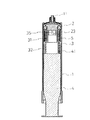
図1は本発明の一実施例を示す縦断面図であり、図2〜図8は本発明の他の実施例を示す縦断面図である。また、図9および図10は図1に示す薬液注入装置の薬液充填及び薬液吐出の状態を示す説明図であり、図11は本発明の薬液注入装置に流量制御手段を備えたチューブを接続した状態を示す図である。
図1〜図8に示すように、本発明の薬液注入装置は、バレル1と、ガスケット2、連結部材3、プランジャ4およびコイルバネ5を含んでなる。バレル1は基端が開放しており、先端にポート部11を備えている。また、ガスケット2はバレル1の内腔に液密かつ摺動自在に挿着されている。連結部材3は先端と基端を有する円筒状部材であり、その先端部31にガスケット1が解除可能に連結され、基端部32にプランジャ4が着脱自在に係合されている。そして、ガスケット1と連結部材3の間にはコイルバネ5が圧縮収容されており、ガスケット2が連結部材3から開放された時、コイルバネ5の弾発力により、ガスケット2が前進して、薬液が吐出されるようになっている。
【0012】
図1〜図4に示す薬液注入装置は、連結部材3の先端部31がバレル1の内径より小さな外径を有する円筒状に形成されたもので、先端部31の外周と基端部32、ガスケット2、バレル1で囲まれる空間に、この円筒状部分を取り巻くようにコイルバネ5が圧縮され収容されている。連結部材3の基端部32とプランジャ4の係合は螺合が好ましく、また、このタイプの場合、プランジャ4の被係合手段41はオス型が好ましい。
【0013】
図1に示すものは、連結部材3の先端部31先端に閉鎖壁33が設けられたもので、閉鎖壁33にはガスケット2の被連結手段、例えばフック21を連結するための連結孔331が設けられており、連結部材3を軸の周りに回転させることにより、ガスケット2を連結部材3から解除することができるようになっている。具体的には、例えば図10に示すような構成が採用される。図10では、連結孔331は長方形に形成されており、フック21は、連結孔331の短径より小さな径の例えば円柱状の柄を有し(これによりフック21は連結孔331の中で回動自在になる)、連結孔331と相似形でこれよりやや小さなサイズに形成されている。フック21は、A−A断面図に示すように、連結孔331に挿着され係合されており、連結部材3を軸の周りに回転させ、B−B断面図に示すように、連結孔331とフック21の向きを一致させると、フック21が連結孔331から外れる。
【0014】
図2に示すものは、連結部材3の先端部31先端の内腔に軸対称に一対の平行な横棒34が設けられたもので、この一対の横棒34の間に、フック22が回動自在に挿着され係合されており、連結部材3を軸の周りに回転させることにより、ガスケット2を連結部材3から解除することができるようになっている。フック22は、横棒34の間隔より幅が狭く、横棒34の間隔より長径であり、一対の横棒34の間隔より小さな径の例えば円柱状の柄を有している。この構成では、連結部材3を軸の周りに回転させ、フック22の向きを横棒34の向きと一致させると、フック22が横棒34から外れる。横棒34は1個または2個設けられるが、図に示すように、軸対称かつ平行に一対設けるのが好ましい。
【0015】
図3に示すものは、連結部材3の先端部31側壁に、縦方向と横方向のスリットからなるL字状スリット35が設けられるとともに、ガスケット2に、L字状スリット35の横方向のスリットで係合する被係合手段、例えば図に示すような突起23が設けられてなるもので、連結部材3を軸の周りに回転させることにより、ガスケット2を連結部材3から解除することができるようになっている。この構成では、連結部材3を軸の周りに回転させ、突起23を縦方向のスリットの所に移動させると、突起23がL字状スリット35から外れる。L字状スリット35は1個または複数個設けることができるが、軸対称に一対設けるのが好ましい。
【0016】
図4に示すものは、連結部材3の先端部31基端に閉鎖壁36が設けられたもので、閉鎖壁36にはその軸上にガスケット2の被連結手段、例えばフック24を連結するための円形の連結孔361が設けられている。フック24には長尺な可撓性を有する柄241が設けられており、フック24を手などで内側に撓ませることにより、ガスケット2を連結部材3から解除することができるようになっている。フック24は1個または2個設けられるが、図に示すように、軸対称に一対設けるのが好ましい。
【0017】
図5〜図7に示す薬液注入装置は、ガスケット2に長尺な柄を有するフックが設けられたもので、先端部31とガスケット2、バレル1で囲まれる空間に、この柄を取り巻くようにコイルバネ5が圧縮され収容されている。連結部材3の基端部32とプランジャ4の係合は螺合が好ましく、また、このタイプの場合、プランジャ4の被係合手段42はメス型が好ましい。
【0018】
図5に示すものは、連結部材3の先端が閉鎖壁37に形成されたもので、閉鎖壁37にはガスケット2の被連結手段、例えばフック25を連結するための連結孔371が設けられており、連結部材3を軸の周りに回転させることにより、ガスケット2を連結部材3から解除することができるようになっている。連結孔371は長方形に形成されており、フック25は、連結孔371の短径より小さな径の例えば円柱状の長尺な柄251を有し(これによりフック25は連結孔371の中で回動自在になる)、連結孔371と相似形でこれよりやや小さなサイズに形成されている。フック25は連結孔371に挿着され係合されており、連結部材3を軸の周りに回転させ、連結孔371とフック25の向きを一致させると、フック25が連結孔371から外れる。
【0019】
図6に示すものは、連結部材3の先端に閉鎖壁38が設けられたもので、閉鎖壁38にはその軸上にガスケット2の被連結手段、例えばフック26を連結するための円形の連結孔381が設けられている。フック26には長尺な可撓性を有する柄261が設けられており、フック26を手などで内側に撓ませることにより、ガスケット2を連結部材3から解除することができるようになっている。フック26は1個または2個設けられるが、図に示すように、軸対称に一対設けるのが好ましい。
【0020】
図7に示すものは、連結部材3の先端内腔に軸対称に一対の平行な横棒39が設けられたもので、この一対の横棒39の間に、フック27が回動自在に挿着され係合されており、連結部材3を軸の周りに回転させることにより、ガスケット2を連結部材3から解除することができるようになっている。フック27は、横棒39の間隔より幅が狭く、横棒39の間隔より長径であり、一対の横棒39の間隔より小さな径の例えば円柱状の長尺な柄271を有している。この構成では、連結部材3を軸の周りに回転させ、フック27の向きを横棒39の向きと一致させると、フック27が横棒39から外れる。横棒39は1個または2個設けられるが、図に示すように、軸対称かつ平行に一対設けるのが好ましい。
【0021】
図8に示す薬液注入装置は、ガスケット2の外周面とバレル1の内周面に、夫々ガスケット2が軸の回りに回転するのを防止するための複数の縦リブ28、12を設けたものである。これにより、連結部材3を回転させたときにガスケット2が一緒に回転するのを防ぐことができるので、連結部材3からガスケット2を確実に解除することができる。
【0022】
次に本発明の薬液注入装置の使用について図9〜11を用いて説明する。
図1に示す薬液注入装置Aは、始めは図9(a)のような状態になっている。図9(b)のようにポート部11を薬液容器などに接続し、薬液の中に入れてプランジャ4を引くと、バレル1中に薬液が充填される。次に、図9(c)のようにプランジャ4を軸の周りに回転させてプランジャ4を連結部材3から外す。このとき、連結部材3の連結孔331とガスケット2のフック21は、図10(a)に示すような状態で係合している。薬液注入装置Aはこの状態で、図11に示すように、流量制御装置16を備えたチューブBに接続される。図中、15はクランプ、17はカテーテル(図示していない)への接続手段であり、クランプ15は閉じられている。次に、図9(d)のように連結部材3を手などで軸の周りに回転させ、図10(b)のように連結部材3の連結孔331とガスケット2のフック21の向きを一致させると、ガスケット2と連結部材3の連結が解除される。図11においてクランプ15を外すと、図10(c)に示すように、コイルバネ5の弾発力によりガスケット2が前進させられ、バレル1に充填された薬液が吐出される。
【0023】
【発明の効果】
以上説明してきたことから明らかなように、本発明の薬液注入装置を採用することにより、プランジャを引くだけの簡単な操作で、注入器本体たるバレル内に直接薬液を充填することができるので、操作者の労力が軽減される。また、注入器本体が注射器状であるため薬液残量を正確に把握することができる。
【図面の簡単な説明】
【図1】 図1は本発明の一実施例を示す縦断面図である。
【図2】 本発明の他の実施例を示す縦断面図である。
【図3】 本発明の他の実施例を示す縦断面図である。
【図4】 本発明の他の実施例を示す縦断面図である。
【図5】 本発明の他の実施例を示す縦断面図である。
【図6】 本発明の他の実施例を示す縦断面図である。
【図7】 本発明の他の実施例を示す縦断面図である。
【図8】 本発明の他の実施例を示す縦断面図である。
【図9】 図1に示す薬液注入装置の薬液充填及び薬液吐出の状態を示す説明図である。
【図10】 図1に示す薬液注入装置の薬液充填及び薬液吐出の状態を示す説明図である。
【図11】 本発明の薬液注入装置に流量制御手段を備えたチューブを接続した状態を示す図である。本発明の一実施例を示す平面図である。
【符号の説明】
1 バレル
11 ポート部
2 ガスケット
21、22、24、25、26、27 フック
23 突起
241、251、261、271 柄
3 連結部材
31 先端部
32 基端部
33、36、37、38 閉鎖壁
331、361、371、381 連結孔
34、39 横棒
35 スリット
4 プランジャ
41 オス型被係合手段
42 メス型被係合手段
5 コイルバネ
A 薬液注入装置
B チューブ[0001]
BACKGROUND OF THE INVENTION
The present invention relates to a chemical liquid injector. More specifically, the present invention relates to a drug solution injection device for injecting a drug solution into a blood vessel, epidural, subcutaneous, bladder or the like using a coil spring.
[0002]
[Prior art]
Conventionally, as a means of injecting a drug solution such as an antibiotic or an anticancer drug into a blood vessel or epidural by a minute amount, a balloon made of a rubber elastic material is filled with the drug solution and the contraction force of the balloon is used for a relatively long time. A chemical injection device that continuously injects a chemical into a blood vessel or the like has been used (Japanese Patent Laid-Open No. 4-2360). This is a chemical solution injection device using a multi-layer structure balloon in which a hollow inner surface of a natural rubber tubular body is covered with a silicone resin, and is connected to the balloon, a housing for housing the balloon, and the balloon. The flow control means is included as a constituent element, and the balloon is a container for storing the chemical solution, and also serves as a power source for injecting the chemical solution.
[0003]
However, the drug solution injection device using the contraction force of the balloon cannot avoid the influence of the balloon forming material. In other words, since the balloon is made of a rubber elastic material, the pressure for injecting the drug solution during infusion changes over time, and it has the disadvantage that the drug solution cannot be injected at an accurate speed and quantity, and contains the drug solution. Therefore, there is a drawback that it is necessary to select a rubber that does not elute.
[0004]
In order to solve the above drawbacks, there has been proposed a syringe-type chemical liquid injector that uses, for example, an elastic material such as a coil spring, a constant load spring, or a rubber wire as a driving means (Japanese Patent Laid-Open No. 7-509). Issue gazette).
However, since the plunger is moved forward by the driving means, it is necessary to accommodate the syringe in the capsule so that the plunger is not pushed by touching the hand or the like. However, it is not suitable for carrying around and using.
[0005]
[Problems to be solved by the invention]
The present invention has been made in view of the above circumstances, and provides a chemical solution injection device that can directly fill a chemical solution into the injection device main body from a chemical solution bottle or the like and can accurately grasp the remaining amount of the chemical solution. The purpose is to do.
[0006]
[Means for Solving the Problems]
As a result of intensive studies to solve the above-mentioned problems, the present inventors have conceived that the entire apparatus can be reduced in size by directly advancing the gasket with the driving means, and the present invention has been completed. That is, the present invention has a base-open barrel having a port portion at the tip, a gasket that is liquid-tightly and slidably inserted into the lumen of the barrel, and a tip and a base. A cylindrical connecting member in which the gasket is releasably connected to the distal end side, and a plunger is detachably engaged to the proximal end side; the plunger; and a coil spring compressed and accommodated between the gasket and the connecting member And a chemical injection device in which the gasket released from the connecting member is advanced by the elastic force of the coil spring so that the chemical is discharged.
[0007]
Here, in order to compress and house the coil spring between the gasket and the connecting member, the tip of the connecting member is formed in a cylindrical shape having an outer diameter smaller than the inner diameter of the barrel, and the coil spring is wound around the tip. In addition, a hook having a long handle may be provided on the gasket, and a coil spring may be stored so as to wind the handle of the hook.
[0008]
When the tip of the connecting member is formed in a cylindrical shape having an outer diameter smaller than the inner diameter of the barrel and the coil spring is accommodated so as to wind this tip, the connection between the gasket and the connecting member is performed by connecting the connecting member to the shaft. It may be possible to release by rotating around, and a closing wall having a circular connecting hole on the shaft is provided on the distal end side of the connecting member, and the gasket has a long and flexible shape. A hook that can be inserted into and engaged with the connection hole is provided, and the hook may be released by bending the hook inward.
[0009]
If the gasket is provided with a hook having a long handle and a coil spring is accommodated so as to wind the handle of the hook, a closing wall having a connecting hole on the shaft is provided at the tip of the connecting member. Even if the hook is inserted into the connection hole so as to be rotatable and engageable, the connection between the gasket and the connection member can be released by rotating the connection member around the shaft. In addition, the hook may be formed as a flexible hook, and the connection between the gasket and the connecting member may be released by bending the hook inward. Further, it stretched the cross bar in the lumen of the distal end side of the connecting member and engaged with the hook to the crossbar, released by the coupling of the gasket and the coupling member rotates the coupling member about an axis You may be made to do. In this case, a cylindrical portion having an outer diameter smaller than the inner diameter of the barrel is projected at the tip of the connecting member, and a hook and a coil spring wound around the handle of the hook are accommodated in the inner cavity of the cylindrical portion. Also good.
[0010]
The engagement between the base end portion of the connecting member and the plunger is not limited, but it is preferable that the plunger can be released by rotating the plunger around an axis. In addition, on the outer peripheral surface of the gasket and the inner peripheral surface of the barrel, for example, a plurality of vertical ribs are provided to prevent the gasket from rotating around the shaft, and the plunger and the connecting member are rotated around the shaft. It is desirable to prevent the gasket from rotating when the vertical ribs are engaged with each other.
[0011]
DETAILED DESCRIPTION OF THE INVENTION
Next, embodiments of the present invention will be described with reference to the drawings.
FIG. 1 is a longitudinal sectional view showing an embodiment of the present invention, and FIGS. 2 to 8 are longitudinal sectional views showing other embodiments of the present invention. 9 and 10 are explanatory views showing the state of the chemical solution filling and the chemical solution discharge of the chemical solution injection apparatus shown in FIG. 1, and FIG. It is a figure which shows a state.
As shown in FIGS. 1 to 8, the chemical liquid injector of the present invention includes a
[0012]
1 to 4, the
[0013]
1 shows a structure in which a
[0014]
In FIG. 2, a pair of parallel
[0015]
3, an L-shaped
[0016]
In FIG. 4, a closing
[0017]
5 to 7, a hook having a long handle is provided on the
[0018]
5 shows a structure in which the tip of the connecting
[0019]
6 shows a structure in which a
[0020]
In the structure shown in FIG. 7, a pair of parallel
[0021]
The chemical injection device shown in FIG. 8 is provided with a plurality of
[0022]
Next, the use of the chemical liquid injector of the present invention will be described with reference to FIGS.
The chemical solution injector A shown in FIG. 1 is initially in a state as shown in FIG. When the
[0023]
【The invention's effect】
As is apparent from the above description, by adopting the chemical solution injection device of the present invention, the chemical solution can be directly filled into the barrel as the injector body by a simple operation by simply pulling the plunger. The labor of the operator is reduced. Moreover, since the injector body is in the shape of a syringe, the remaining amount of the drug solution can be accurately grasped.
[Brief description of the drawings]
FIG. 1 is a longitudinal sectional view showing an embodiment of the present invention.
FIG. 2 is a longitudinal sectional view showing another embodiment of the present invention.
FIG. 3 is a longitudinal sectional view showing another embodiment of the present invention.
FIG. 4 is a longitudinal sectional view showing another embodiment of the present invention.
FIG. 5 is a longitudinal sectional view showing another embodiment of the present invention.
FIG. 6 is a longitudinal sectional view showing another embodiment of the present invention.
FIG. 7 is a longitudinal sectional view showing another embodiment of the present invention.
FIG. 8 is a longitudinal sectional view showing another embodiment of the present invention.
FIG. 9 is an explanatory view showing a state of chemical liquid filling and chemical liquid discharge of the chemical liquid injector shown in FIG. 1;
10 is an explanatory view showing a state of chemical liquid filling and chemical liquid discharge of the chemical liquid injector shown in FIG. 1; FIG.
FIG. 11 is a view showing a state in which a tube having a flow rate control unit is connected to the chemical injection device of the present invention. It is a top view which shows one Example of this invention.
[Explanation of symbols]
1
Claims (18)
Priority Applications (4)
| Application Number | Priority Date | Filing Date | Title |
|---|---|---|---|
| JP26565099A JP3941088B2 (en) | 1999-09-20 | 1999-09-20 | Chemical injection device |
| DE60016530T DE60016530T2 (en) | 1999-09-20 | 2000-09-19 | Delivery device for drug solutions |
| EP00120471A EP1084723B1 (en) | 1999-09-20 | 2000-09-19 | Drug solution delivery device |
| US09/666,591 US6565531B1 (en) | 1999-09-20 | 2000-09-20 | Drug solution delivery device |
Applications Claiming Priority (1)
| Application Number | Priority Date | Filing Date | Title |
|---|---|---|---|
| JP26565099A JP3941088B2 (en) | 1999-09-20 | 1999-09-20 | Chemical injection device |
Publications (3)
| Publication Number | Publication Date |
|---|---|
| JP2001087382A JP2001087382A (en) | 2001-04-03 |
| JP2001087382A5 JP2001087382A5 (en) | 2004-09-30 |
| JP3941088B2 true JP3941088B2 (en) | 2007-07-04 |
Family
ID=17420092
Family Applications (1)
| Application Number | Title | Priority Date | Filing Date |
|---|---|---|---|
| JP26565099A Expired - Fee Related JP3941088B2 (en) | 1999-09-20 | 1999-09-20 | Chemical injection device |
Country Status (4)
| Country | Link |
|---|---|
| US (1) | US6565531B1 (en) |
| EP (1) | EP1084723B1 (en) |
| JP (1) | JP3941088B2 (en) |
| DE (1) | DE60016530T2 (en) |
Families Citing this family (8)
| Publication number | Priority date | Publication date | Assignee | Title |
|---|---|---|---|---|
| CA2523267C (en) | 2003-04-23 | 2013-09-03 | Biovalve Technologies, Inc. | Hydraulically actuated pump for long duration medicament administration |
| WO2006014425A1 (en) | 2004-07-02 | 2006-02-09 | Biovalve Technologies, Inc. | Methods and devices for delivering glp-1 and uses thereof |
| FI116612B (en) * | 2004-07-05 | 2006-01-13 | Biohit Oyj | A suction device |
| DE102005063497B4 (en) * | 2005-05-24 | 2009-09-24 | Tecpharma Licensing Ag | Plastic spring |
| WO2007115039A2 (en) | 2006-03-30 | 2007-10-11 | Valeritas, Llc | Multi-cartridge fluid delivery device |
| AU2009326323B2 (en) * | 2008-12-12 | 2013-01-17 | Shl Group Ab | Medicament delivery device |
| EP2981315A4 (en) * | 2013-04-03 | 2016-11-16 | Smiths Medical Asd Inc | Devices for prevention of unintentional syringe aspiration |
| JP6861694B2 (en) * | 2015-07-08 | 2021-04-21 | サノフイSanofi | Drug delivery device including load indicator |
Family Cites Families (16)
| Publication number | Priority date | Publication date | Assignee | Title |
|---|---|---|---|---|
| US2183482A (en) * | 1936-12-23 | 1939-12-12 | Schmid Inc Julius | Injector |
| US2605765A (en) * | 1947-06-05 | 1952-08-05 | Kollsman Paul | Automatic syringe |
| US3214067A (en) * | 1962-09-11 | 1965-10-26 | Thomas R Linington | Fluid dispenser |
| US4735611A (en) * | 1987-03-30 | 1988-04-05 | Midwest Sport Distributors, Inc. | Projectile syringe for blowpipe |
| US4966585A (en) * | 1988-05-31 | 1990-10-30 | Gangemi Ronald J | Infusion apparatus |
| US5100389A (en) * | 1988-06-21 | 1992-03-31 | Vaillancourt Vincent L | Ambulatory infusion pump |
| US4991742A (en) * | 1989-08-01 | 1991-02-12 | Chang Chin Fu | Automatic drip bottle set |
| US4997420A (en) * | 1989-12-28 | 1991-03-05 | Lefevre Robert J | Portable drug delivery device including pump with tapered barrel |
| JPH042360A (en) | 1990-04-19 | 1992-01-07 | Nissho Corp | Balloon infuser |
| JPH0451966A (en) * | 1990-06-19 | 1992-02-20 | Toichi Ishikawa | Medical fluid continuous injector |
| US5140862A (en) * | 1991-02-06 | 1992-08-25 | Pappalardo Joseph T | Injection pump calibration device |
| JPH07509A (en) | 1992-07-31 | 1995-01-06 | Nissho Corp | Medicinal liquid injecting device |
| US5389075A (en) * | 1993-06-14 | 1995-02-14 | Vladimirsky; Roman | Single-use hypodermic syringe |
| US6019747A (en) * | 1997-10-21 | 2000-02-01 | I-Flow Corporation | Spring-actuated infusion syringe |
| US5976112A (en) * | 1997-11-07 | 1999-11-02 | Lyza Weiss Jennings & Shea | Injector syringe |
| US6083201A (en) * | 1999-01-07 | 2000-07-04 | Mckinley Medical, Llp | Multi-dose infusion pump |
-
1999
- 1999-09-20 JP JP26565099A patent/JP3941088B2/en not_active Expired - Fee Related
-
2000
- 2000-09-19 EP EP00120471A patent/EP1084723B1/en not_active Expired - Lifetime
- 2000-09-19 DE DE60016530T patent/DE60016530T2/en not_active Expired - Lifetime
- 2000-09-20 US US09/666,591 patent/US6565531B1/en not_active Expired - Fee Related
Also Published As
| Publication number | Publication date |
|---|---|
| DE60016530T2 (en) | 2005-04-14 |
| DE60016530D1 (en) | 2005-01-13 |
| JP2001087382A (en) | 2001-04-03 |
| EP1084723B1 (en) | 2004-12-08 |
| EP1084723A1 (en) | 2001-03-21 |
| US6565531B1 (en) | 2003-05-20 |
Similar Documents
| Publication | Publication Date | Title |
|---|---|---|
| US4929238A (en) | Multi-pressure injector device | |
| EP3007744B1 (en) | Portable fluid delivery system | |
| US9399095B2 (en) | Compact non-electric medicament infuser | |
| US4753638A (en) | Medical syringe | |
| JP5480249B2 (en) | Apparatus and method for depth controlled injection | |
| US8412310B2 (en) | Locking syringe with integrated bias member | |
| EP1023094B1 (en) | Pulse fluid infusion systems | |
| US20060173415A1 (en) | Syringe adaptor | |
| CN102869399A (en) | Medicament delivery device | |
| WO1999019009A1 (en) | One-hand pulse pump | |
| AU2018334143B2 (en) | Sliding syringe cap for separate filling and delivery | |
| WO1989009071A1 (en) | Disposable control syringe | |
| JP3941088B2 (en) | Chemical injection device | |
| US20170290985A1 (en) | Revolving multi-cartridge hypodermic syringe and method of use | |
| US10342742B2 (en) | Bolus feeding device | |
| US20100087779A1 (en) | Instrument and device for varicose sclerotherapy | |
| CN113144347B (en) | Processor for medical injector and use method thereof | |
| JP3181040U (en) | Semi-solid nutrient infusion aid | |
| WO2018036763A1 (en) | Portable liquid drug delivery device | |
| JP7140359B2 (en) | Indwelling needles and medical connector devices | |
| JP4096349B2 (en) | Chemical solution continuous injector | |
| JP2012055592A (en) | Drug solution administration appliance | |
| JPS62281960A (en) | Portable injection pump |
Legal Events
| Date | Code | Title | Description |
|---|---|---|---|
| A131 | Notification of reasons for refusal |
Free format text: JAPANESE INTERMEDIATE CODE: A131 Effective date: 20061218 |
|
| A521 | Written amendment |
Free format text: JAPANESE INTERMEDIATE CODE: A523 Effective date: 20070214 |
|
| TRDD | Decision of grant or rejection written | ||
| A01 | Written decision to grant a patent or to grant a registration (utility model) |
Free format text: JAPANESE INTERMEDIATE CODE: A01 Effective date: 20070312 |
|
| A61 | First payment of annual fees (during grant procedure) |
Free format text: JAPANESE INTERMEDIATE CODE: A61 Effective date: 20070325 |
|
| R150 | Certificate of patent or registration of utility model |
Free format text: JAPANESE INTERMEDIATE CODE: R150 |
|
| FPAY | Renewal fee payment (event date is renewal date of database) |
Free format text: PAYMENT UNTIL: 20130413 Year of fee payment: 6 |
|
| LAPS | Cancellation because of no payment of annual fees |