JP3937329B2 - Moving nozzle inkjet actuator - Google Patents
Moving nozzle inkjet actuator Download PDFInfo
- Publication number
- JP3937329B2 JP3937329B2 JP2002537549A JP2002537549A JP3937329B2 JP 3937329 B2 JP3937329 B2 JP 3937329B2 JP 2002537549 A JP2002537549 A JP 2002537549A JP 2002537549 A JP2002537549 A JP 2002537549A JP 3937329 B2 JP3937329 B2 JP 3937329B2
- Authority
- JP
- Japan
- Prior art keywords
- ink
- nozzle
- roof portion
- actuator
- side wall
- Prior art date
- Legal status (The legal status is an assumption and is not a legal conclusion. Google has not performed a legal analysis and makes no representation as to the accuracy of the status listed.)
- Expired - Fee Related
Links
- 238000005452 bending Methods 0.000 claims description 27
- 239000000758 substrate Substances 0.000 claims description 16
- 230000002093 peripheral effect Effects 0.000 claims description 7
- 238000007639 printing Methods 0.000 claims description 5
- 238000010438 heat treatment Methods 0.000 description 6
- 238000005516 engineering process Methods 0.000 description 4
- 230000000717 retained effect Effects 0.000 description 4
- 239000012530 fluid Substances 0.000 description 2
- 239000012535 impurity Substances 0.000 description 2
- 238000007789 sealing Methods 0.000 description 2
- 230000015572 biosynthetic process Effects 0.000 description 1
- 239000007788 liquid Substances 0.000 description 1
- 238000002360 preparation method Methods 0.000 description 1
Images


Classifications
-
- B—PERFORMING OPERATIONS; TRANSPORTING
- B41—PRINTING; LINING MACHINES; TYPEWRITERS; STAMPS
- B41J—TYPEWRITERS; SELECTIVE PRINTING MECHANISMS, i.e. MECHANISMS PRINTING OTHERWISE THAN FROM A FORME; CORRECTION OF TYPOGRAPHICAL ERRORS
- B41J2/00—Typewriters or selective printing mechanisms characterised by the printing or marking process for which they are designed
- B41J2/005—Typewriters or selective printing mechanisms characterised by the printing or marking process for which they are designed characterised by bringing liquid or particles selectively into contact with a printing material
- B41J2/01—Ink jet
- B41J2/135—Nozzles
- B41J2/14—Structure thereof only for on-demand ink jet heads
- B41J2/14427—Structure of ink jet print heads with thermal bend detached actuators
-
- B—PERFORMING OPERATIONS; TRANSPORTING
- B41—PRINTING; LINING MACHINES; TYPEWRITERS; STAMPS
- B41J—TYPEWRITERS; SELECTIVE PRINTING MECHANISMS, i.e. MECHANISMS PRINTING OTHERWISE THAN FROM A FORME; CORRECTION OF TYPOGRAPHICAL ERRORS
- B41J2/00—Typewriters or selective printing mechanisms characterised by the printing or marking process for which they are designed
- B41J2/005—Typewriters or selective printing mechanisms characterised by the printing or marking process for which they are designed characterised by bringing liquid or particles selectively into contact with a printing material
- B41J2/01—Ink jet
- B41J2/015—Ink jet characterised by the jet generation process
- B41J2/04—Ink jet characterised by the jet generation process generating single droplets or particles on demand
- B41J2/045—Ink jet characterised by the jet generation process generating single droplets or particles on demand by pressure, e.g. electromechanical transducers
-
- B—PERFORMING OPERATIONS; TRANSPORTING
- B41—PRINTING; LINING MACHINES; TYPEWRITERS; STAMPS
- B41J—TYPEWRITERS; SELECTIVE PRINTING MECHANISMS, i.e. MECHANISMS PRINTING OTHERWISE THAN FROM A FORME; CORRECTION OF TYPOGRAPHICAL ERRORS
- B41J2/00—Typewriters or selective printing mechanisms characterised by the printing or marking process for which they are designed
- B41J2/005—Typewriters or selective printing mechanisms characterised by the printing or marking process for which they are designed characterised by bringing liquid or particles selectively into contact with a printing material
- B41J2/01—Ink jet
- B41J2/135—Nozzles
- B41J2/14—Structure thereof only for on-demand ink jet heads
- B41J2/14427—Structure of ink jet print heads with thermal bend detached actuators
- B41J2002/14435—Moving nozzle made of thermal bend detached actuator
Abstract
Description
【0001】
【発明の属する技術分野】
本発明はインクジェットプリントヘッドに関する。更に具体的には、本発明は移動ノズルインクジェットアクチュエータに関する。
【0002】
【発明の背景】
マイクロエレクトロメカニカルシステム(micro-electro mechanical system ; MEMS)テクノロジーを使用して製造される大部分のインクジェットプリントヘッドは、ノズルチャンバを使用する構成として提案されている。このノズルチャンバは、基板最上部のMEMS層の中に形成される。各々のチャンバは、或る形をしたアクチュエータによって作動される移動可能なパドルを設けられ、アクチュエータで電気信号が受け取られたとき、インクはチャンバに関連したノズルを介して液滴を強制する。そのような構成は、本出願人の国際特許出願PCT/AU99/00894の開示によって類型化されている。
【0003】
パドルを使用せず、ノズルチャンバのサイズを縮小することによって、インク液滴がノズルから強制されることによって得られる利点を実現することに、本発明は端を発している。それを達成するために、アクチュエータがチャンバの中でノズル自身を下方へ動かすようにし、それによってパドルを不要にし、構成を簡単にして、ノズルチャンバからのインクが漏れにくくする環境を提供することが知られている。
【0004】
【課題を解決するための手段】
複数のノズルを含み、各々のノズルがインク液滴を印刷面の方向へ噴出するように構成されたインクジェットプリントヘッドであって、各々のノズルは、外部アクチュエータと、屋根部分と、基板の中の少なくとも1つの導管を介してインクを供給されるように構成されており基板上に配置されている関連ノズルチャンバとを有し、屋根部分は、インクと接触する内面及び内面と対向する外面を有し、屋根部分には、ノズル開口が内面から外面に貫通して形成されており、外面は、外部アクチュエータに動作的に連結されており、これにより、アクチュエータが屋根部分を印刷面から離れるように移動させて導管内のインクの粘性抗力によって、ノズルチャンバに供給されたインクをノズル開口から噴出させるインクジェットプリントヘッドが提供される。
【0006】
好ましくは、屋根部分が側壁を有し、前記側壁は、屋根部分の周辺から垂れ下がって、対向する床部分から伸びる周辺側壁との間にギャップを有して前記周辺側壁と重なるように配置されており、それによって、ノズルチャンバを画成する。
【0007】
好ましくは、前記アクチュエータは、屈曲アクチュエータであり、前記屈曲アクチュエータは、近接端でカンチレバービームとして基板に取り付けられ、カンチレバービームの遠位端でノズルチャンバの屋根部分を支持するように配置され、使用中に、ノズルの作動は、屋根部分を床部分の方向へ移動することによって、前記屋根部分の前記ノズル開口を通してインクを噴出する。
【0008】
好ましくは、前記基板の中の導管は、床部分のインク供給開口を介してノズルチャンバと連絡し、インク供給開口は、そこを通るインクの流れを妨害しないように十分な大きさである。
【0009】
好ましくは、屋根部分が下方へ移動したとき、使用中のノズルチャンバのインクは、導管壁の粘性抗力によって導管を逆流しない。
【0010】
【発明の実施の形態】
本発明の範囲の中には他の実施の形態も入るかも知れないが、以下添付の図面を参照して、例示のためにのみ、本発明の1つの好ましい実施の形態を説明する。
【0011】
本明細書の始めに参照された本出願人の同時係属特許出願で説明されるように、MEMS及びCMOSテクノロジを使用して、多数の類似のノズルが同時に製造されることが分かるであろう。
【0012】
説明を明瞭にするために、以下、個々のインクジェットノズルの構成だけを説明する。
【0013】
前記の同時係属特許出願で説明されたタイプの従来のインクジェット構成では、インクはノズルチャンバの中のパドルの運動によってノズルチャンバから噴出されるが、本発明によれば、パドルは存在せず、インクはチャンバの上面の開口(ノズル)を介して噴出される。チャンバは屈曲アクチュエータによって下方へ移動され、チャンバの容積が減少してインクがノズルを介して噴出される。
【0014】
本明細書を通して、「ノズル」の用語は、開口自身ではなく開口を画成する要素として理解されたい。更に、添付の図面を参照するとき、「上方」及び「下方」、並びに類似の相対的用語が使用されるが、これは使用されるインクジェットノズルの方向を限定するものではないことを理解すべきである。
【0015】
ここで添付の図1〜図3を参照すると、ノズルはMEMSテクノロジによって基板1の上に構成される。MEMSテクノロジは、六角形開口3(これは他の適切な構成であってよい)を通ってチャンバ4の中へ開かれたインク供給開口2を画成する。チャンバ4は、床部分5,屋根部分6,及び伸縮式に重なる周辺側壁7並びに8によって画成される。屋根部分6から下方へ垂れ下がる側壁7は、床部分5から上方へ伸びている側壁8の中で、上方及び下方へ移動できる大きさである。
【0016】
噴出ノズルは、屋根部分6に配置されたリム9によって形成され、後で詳細に説明するように、ノズルチャンバからインクを噴出するための開口を画成する。
【0017】
屋根部分6及び下方へ垂れ下がる側壁7は、屈曲アクチュエータ10によって支持される。屈曲アクチュエータ10は、典型的には、非加熱カンチレバーによって制約されるジュール加熱カンチレバーを形成する層から作られる。ジュール加熱カンチレバーの加熱は、ジュール加熱カンチレバーと非加熱カンチレバーとの間に伸び差を生じ、屈曲アクチュエータ10を屈曲させる。
【0018】
屈曲アクチュエータの近接端11は基板1へ固定され、後で詳述するアンカー部材12によって後方への移動を防止され、遠位端13はインクジェットノズルの屋根部分6及び側壁7へ固定されて、それらを支持する。
【0019】
使用中に、インクは、適当な方式で、しかし典型的には前述した出願人の同時係属特許出願で説明されるように、通路2及び開口3を介してノズルチャンバの中へ供給される。ノズルチャンバからインクの液滴を噴出することが望まれる場合、電流が屈曲アクチュエータ10へ供給され、アクチュエータを図2で示される位置へ屈曲させ、屋根部分6を床部分5に向かって下方へ移動させる。この相対的移動は、ノズルチャンバの容積を減少させ、14(図2)で示されるようにノズルリム9を介してインクを上方へ膨らませる。インクは、14で、インクの表面張力によって小滴へ形成される。
【0020】
電流が屈曲アクチュエータ10から取り去られると、アクチュエータは、図3で示される直線構成へ復帰し、ノズルチャンバの屋根部分6を上方の元のロケーションへ移動させる。部分的に形成されたインク小滴14の運動量によって、小滴は上方への移動を継続し、図3で示されるようにインク液滴15を形成する。インク液滴15は隣接した紙面又は他の印刷される物体へ投射される。
【0021】
本発明の1つの形式において、床部分5の開口3は、ノズルチャンバの断面と比較して比較的に大きく、インク小滴は、開口2の側壁及びインクリザーバ(図示されていない)から開口2へ続く供給導管の中の粘性抗力によって、屋根部分6が下方へ移動したときにノズルリム9を介して噴出される。これはインクジェットノズルの多くの従来の形式と区別される点である。従来の形式では、作動されたとき、インクがノズルリムを介して噴出されるようにするノズルチャンバの中の「背圧」は、ノズルチャンバの隣接したロケーションの1つ又は複数のバッフルによって生じる。このタイプの構成は、前述したタイプの移動ノズルインクジェットと一緒に使用されることができ、後に図9及び図10を参照して詳細に説明するが、図1〜図3に示される本発明の形式では、背圧は、主として供給導管の中の粘性抗力とインク慣性によって形成される。
【0022】
作動中、即ち、屈曲アクチュエータ10が屈曲する間に、ノズルチャンバからのインク漏れを防止するため、側壁7及び8の間に流体シーリングが形成される。これについては、以下図3及び図4を参照して詳細に説明する。
【0023】
インクは、側壁7及び8の幾何学的特徴によって屋根部分6及び床部分5の相対的移動の間にノズルチャンバの中に保持される。前記幾何学的特徴は、インクが表面張力によってノズルチャンバの中に保持されることを確実にする。このため、下方に垂れ下がる側壁7と上方へ突き出る側壁8の対向表面16との間に、非常に微少なギャップが設けられる。図4で明瞭に分かるように、インク(陰影を付けられた区域)は、2つの側壁の近接によって、下方に垂れ下がる側壁7と上方に伸びる側壁の内面16との間の小さな開口の中に制限される。これは、側壁の近接が非常に近いため、インクが表面張力によって自由開口17を横切って「自己シーリング」することを確実にする。
【0024】
不純物、又は表面張力を破る他の要因があるため、表面張力の制約を逃れるインクに備えて、上方に伸びる側壁8は、上方を向く溝の形式を与えられる。この溝は、内面16だけでなく、間隔をあけられた平行外面18を有し、2つの表面の間にU形溝19が形成される。表面7及び16の間の表面張力から逃れるインク液滴は、U形溝の中へ流れ込み、ノズル層の表面を横切って「吐き出される」代わりに、U形溝の中に保持される。このようにして、二重壁流体シーリングが形成され、このシーリングは、移動ノズル機構の中にインクを保持するのに効果的である。
【0025】
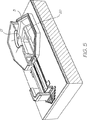
本発明者の同時係属出願の幾つかで説明したように、或る場合には、ノズル開口の中に堆積する不純物を取り除き、作動されたノズルから小滴をクリーン及びクリアに噴出することを確実にするために、「ノズル突き棒」を設けることが望ましい。移動ノズルインクジェットと組み合わせて突き棒を使用する本発明の構成は、添付の図5、図6、及び図7に示される。
【0026】
図5は図1と類似の図であるが、ノズルチャンバの床の開口3を横切ってブリッジ20が付加されている。ブリッジの上には、作動中にノズル面を通って突き出るサイズを有する上方に伸びる突き棒21が取り付けられる。
【0027】
図6から分かるように、屈曲アクチュエータ10が曲げられて屋根部分6が下方へ移動したとき、突き棒21は、ノズルリム9の開口を通って突き上げられ、膨らんだインク液滴14の中へ入り込む。
【0028】
図7で示されるように屈曲アクチュエータ10が真っ直ぐになったとき、屋根部分6は元の位置へ戻るので、インク小滴が形成され、前述したように噴出され、突き棒21が働いて、ノズルリムを横切って形成される乾燥インクを取り除くか破壊する。そうでないと、乾燥したインクはノズルを塞ぐであろう。
【0029】
理解されるように、屈曲アクチュエータ10が曲げられて、屋根部分を図2で示される下方位置へ移動させると、屋根部分は床部分5に対して傾き、インク小滴の形成点で、印刷面と平行でない方向へノズルを移動させる。この方向は、もし補正されないと、床部分5の平面及び一般的なノズル層に対して全く垂直でない方向へノズルからのインク小滴15を噴出するであろう。これは印刷の不正確を生じるであろう。特に、或るノズルは1つの方向を向き、他のノズルは異なった方向、典型的には反対の方向を向くようになるであろう。
【0030】
この非垂直運動の補正は、図8で明瞭に示されるように、非対称形状を有するノズルリム9を設けることによって達成することができる。ノズルは、典型的には、屈曲アクチュエータ10に近い端部22にわたって広くかつ平坦であり、屈曲アクチュエータから遠い端部23で狭くかつより尖っている。端部23におけるノズルリムの狭さは、ノズルの狭い部分で表面張力の力を増加し、液滴がノズルから噴出されるとき、矢印24Aによって示されるように、屈曲アクチュエータへ向かう方向の正味の液滴ベクトル力を生じる。この正味の力は、屋根部分6と垂直でない方向へインク液滴を推進し、従ってインク液滴噴出点で屋根部分の傾斜方向を補償するように調整されることができる。
【0031】
ノズルリム9の形状及び特性を注意深く調整することによって、作動中の屋根部分6の傾斜を完全に補償し、床部分5と垂直な方向へノズルからのインク液滴を推進することができる。
【0032】
前述したように、ノズルチャンバの中に保持されるインクの背圧は、供給導管の中の粘性抗力によって提供されてよいが、ノズルの近くの顕著な狭窄によって移動ノズルインクジェットに背圧を提供することもできる。この狭窄は、典型的には、図9及び図10で明瞭に分かるように、基板層の中に設けられる。図9は側壁8を示すが、側壁8から1つ又は複数のバッフル部材24が内部へ伸び、制限された断面の開口25がノズルチャンバの直下に生じている。この開口の形成は、図を明瞭にするため上部層(図9に示される)を取り除かれた図10で見ることができる。本発明のこの形式は、補助的構成部品、例えばパワートレース及び信号トレースを隣接して配置することを可能にする。これは、或る構成及び移動ノズルインクジェットの意図された使用で望ましいことである。このような制限バッフルの使用は、上記のような利点を有するが、ノズルチャンバへの再充填時間を長くし、或る使用の場合にプリンタの動作速度を不当に制限するかも知れない。
【0033】
遠位端13で結合された非加熱カンチレバー29の上に配置されたジュール加熱カンチレバー28から形成される屈曲アクチュエータは、ジュール加熱カンチレバー28へ電流を供給している間、ジュール加熱カンチレバー28と非加熱カンチレバー29との間の相対的移動を防止するため、近接端11で固定される必要がある。図11はアンカー12を示す。アンカー12は、ベース部分30及び側面部分31を有するU形構成として提供される。ベース部分30及び側面部分31の各々は、それらの下部端を基板26の中へ形成されるか埋め込まれる。屈曲アクチュエータをU形に形成することは、端部壁30へ大きな剛性を与え、屈曲アクチュエータが運動するとき基板26に対する端部壁30の屈曲又は変形を防止する。
【0034】
非加熱カンチレバー29は、外側へ伸びるタブ32を設けられる。タブ32は、側壁31の凹部33の中に配置され、更なる剛性を与え、アンカー27の近傍で非加熱カンチレバー29とジュール加熱カンチレバー28との間の相対的移動を防止する。
【0035】
このようして、屈曲アクチュエータの近接端は強固に固定され、ジュール加熱カンチレバーと非加熱カンチレバーとの間の相対的移動はアンカーの近傍で防止される。これは、移動ノズルインクジェットの屋根部分6の移動効率を向上する。
【図面の簡単な説明】
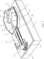
【図1】 移動ノズルインクジェットアセンブリを部分的に破断して示した斜視図である。
【図2】 図1と類似の図であって、インク液滴が移動ノズルから突き出るように曲げられた屈曲アクチュエータを示す図である。
【図3】 図1と類似の図であって、元の位置へ戻されたノズル及びノズルから噴出されたインク液滴を示す図である。
【図4】 図2に示される装置の中間から見た断面図である。
【図5】 図1と類似の図であって、オプションのノズル突き棒の使用を示す図である。
【図6】 図5と類似の図であって、曲げられた屈曲アクチュエータ及びノズルから突き出たインク液滴を示す図である。
【図7】 図5と類似の図であって、真っ直ぐにされた屈曲アクチュエータ及びノズルから噴出しているインク液滴を示す図である。
【図8】 図1と類似の図であって、部分的な破断を有しない図である。
【図9】 図8と類似の図であって、ノズル及び屈曲アクチュエータを取り除き、ノズルチャンバのオプションの狭窄構成を示す図である。
【図10】 図9と類似の図であって、上部層が取り除かれた図である。
【図11】 図1と類似の図であって、図を明瞭にするため、屈曲アクチュエータをカットし、アクチュエータアンカーを取り外した図である。
【符号の説明】
1 基板
2 インク供給開口
3 六角形開口
4 チャンバ
5 床部分
6 屋根部分
7 下方へ垂れ下がる周辺側壁
8 上方へ伸びる周辺側壁
9 リム
10 屈曲アクチュエータ
11 近接端
12 アンカー部材
13 遠位端
26 基板[0001]
BACKGROUND OF THE INVENTION
The present invention relates to an ink jet print head. More specifically, the present invention relates to moving nozzle inkjet actuators.
[0002]
BACKGROUND OF THE INVENTION
Most ink jet printheads manufactured using micro-electro mechanical system (MEMS) technology have been proposed as configurations using a nozzle chamber. This nozzle chamber is formed in the MEMS layer on top of the substrate. Each chamber is provided with a movable paddle that is actuated by a shaped actuator, and when an electrical signal is received at the actuator, the ink forces a droplet through a nozzle associated with the chamber. Such an arrangement is typified by the disclosure of the applicant's international patent application PCT / AU99 / 00894.
[0003]
The present invention originates in realizing the advantages obtained by forcing ink droplets from the nozzles by reducing the size of the nozzle chamber without using paddles. To achieve that, the actuator allows the nozzle itself to move down in the chamber, thereby eliminating the need for paddles, simplifying the configuration, and providing an environment that prevents ink from the nozzle chamber from leaking. Are known.
[0004]
[Means for Solving the Problems]
An inkjet printhead comprising a plurality of nozzles, each nozzle configured to eject ink droplets in the direction of the printing surface, each nozzle being located in an external actuator , a roof portion, and a substrate An associated nozzle chamber configured to be supplied with ink through at least one conduit and disposed on the substrate , the roof portion having an inner surface in contact with the ink and an outer surface opposite the inner surface. In the roof portion, a nozzle opening is formed so as to penetrate from the inner surface to the outer surface, and the outer surface is operatively connected to an external actuator so that the actuator moves the roof portion away from the printing surface. the viscous drag of the ink in the moved by the conduit, an inkjet print head for ejecting ink supplied to the nozzle chamber from the nozzle opening It is provided.
[0006]
Preferably, the roof portion has a side wall, and the side wall hangs from the periphery of the roof portion and is disposed so as to overlap the peripheral side wall with a gap between the side wall and the peripheral side wall extending from the opposite floor portion. Thereby defining a nozzle chamber.
[0007]
Preferably, the actuator is bent actuator, the bending actuator is attached to the substrate as a cantilever beam at the proximal end, it is arranged to support the roof of the nozzle chamber at the distal end of the cantilever beam, in use , the operation of the nozzle by moving the roof portion towards the floor portion to eject ink through the nozzle opening of the roof portion.
[0008]
Preferably, the conduit in the substrate, contact with the nozzle chamber through the ink supply opening of the floor portion, the ink supply opening is large enough so as not to interfere with the flow of ink therethrough.
[0009]
Preferably, when the roof portion moves downward, the ink in the nozzle chamber in use does not flow back through the conduit due to the viscous drag of the conduit wall .
[0010]
DETAILED DESCRIPTION OF THE INVENTION
While other embodiments may fall within the scope of the invention, one preferred embodiment of the invention will now be described, by way of example only, with reference to the accompanying drawings.
[0011]
It will be appreciated that a number of similar nozzles are fabricated simultaneously using MEMS and CMOS technology, as described in Applicant's co-pending patent application referenced at the beginning of this specification.
[0012]
For the sake of clarity, only the configuration of the individual inkjet nozzles will be described below.
[0013]
In a conventional ink jet arrangement of the type described in the aforementioned copending patent application, ink is ejected from the nozzle chamber by the movement of the paddle in the nozzle chamber, but according to the present invention there is no paddle and the ink Is ejected through an opening (nozzle) on the upper surface of the chamber. The chamber is moved downward by a bending actuator, the volume of the chamber is reduced, and ink is ejected through the nozzles.
[0014]
Throughout this specification, the term “nozzle” should be understood as an element that defines an opening rather than the opening itself. Further, when referring to the attached drawings, it should be understood that “upper” and “lower” and similar relative terms are used, but this does not limit the orientation of the inkjet nozzle used. It is.
[0015]
Referring now to the attached FIGS. 1-3, the nozzle is constructed on the substrate 1 by MEMS technology. MEMS technology defines an ink supply opening 2 that opens into the
[0016]
The ejection nozzle is formed by a rim 9 disposed on the roof portion 6 and defines an opening for ejecting ink from the nozzle chamber, as will be described in detail later.
[0017]
The roof portion 6 and the
[0018]
The
[0019]
In use, ink is fed into the nozzle chamber in a suitable manner, but typically through passage 2 and opening 3, as described in the aforementioned applicant's co-pending patent application. If it is desired to eject ink droplets from the nozzle chamber, current is supplied to the
[0020]
When current is removed from the
[0021]
In one form of the invention, the opening 3 in the floor portion 5 is relatively large compared to the cross section of the nozzle chamber, and ink droplets are opened from the sidewalls of the opening 2 and the ink reservoir (not shown) to the opening 2. Due to the viscous drag in the supply conduit that follows, the roof portion 6 is ejected through the nozzle rim 9 as it moves downward. This is a distinction from many conventional types of inkjet nozzles. In conventional formats, the “back pressure” in the nozzle chamber that, when activated, causes ink to be ejected through the nozzle rim is caused by one or more baffles in adjacent locations of the nozzle chamber. This type of configuration can be used with a moving nozzle ink jet of the type described above and will be described in detail later with reference to FIGS. 9 and 10, but of the present invention shown in FIGS. In form, the back pressure is formed primarily by viscous drag and ink inertia in the supply conduit.
[0022]
During operation, i.e., while the bending
[0023]
The ink is retained in the nozzle chamber during the relative movement of the roof portion 6 and the floor portion 5 by the geometric features of the
[0024]
Due to impurities or other factors that break the surface tension, the upwardly extending sidewall 8 is provided with an upward-facing groove type in preparation for ink that escapes surface tension constraints. The groove has not only the
[0025]
As described in some of the inventors' co-pending applications, in some cases it is possible to remove impurities that accumulate in the nozzle openings and ensure that droplets are ejected cleanly and clearly from the activated nozzle. In order to achieve this, it is desirable to provide a “nozzle stick”. The configuration of the present invention using a wand in combination with a moving nozzle ink jet is shown in the attached FIGS. 5, 6, and 7. FIG.
[0026]
FIG. 5 is a view similar to FIG. 1, but with the addition of a
[0027]
As can be seen from FIG. 6, when the bending
[0028]
As shown in FIG. 7, when the bending
[0029]
As can be seen, when the bending
[0030]
This non-vertical motion correction can be achieved by providing a nozzle rim 9 having an asymmetric shape, as clearly shown in FIG. The nozzle is typically wide and flat across the
[0031]
By carefully adjusting the shape and characteristics of the nozzle rim 9, it is possible to completely compensate for the tilting of the roof portion 6 during operation and to propel the ink droplets from the nozzles in a direction perpendicular to the floor portion 5.
[0032]
As described above, the back pressure of the ink retained in the nozzle chamber may be provided by viscous drag in the supply conduit, but provides a back pressure to the moving nozzle ink jet due to significant constriction near the nozzle. You can also. This constriction is typically provided in the substrate layer, as can be clearly seen in FIGS. FIG. 9 shows the side wall 8 from which one or
[0033]
A bending actuator formed from a Joule
[0034]
The
[0035]
In this way, the proximal end of the bending actuator is firmly fixed, and relative movement between the Joule heating cantilever and the non-heating cantilever is prevented in the vicinity of the anchor. This improves the movement efficiency of the roof portion 6 of the moving nozzle inkjet.
[Brief description of the drawings]
FIG. 1 is a perspective view of a moving nozzle inkjet assembly partially cut away.
FIG. 2 is a view similar to FIG. 1 and showing a bending actuator bent so that an ink droplet protrudes from a moving nozzle;
FIG. 3 is a view similar to FIG. 1 and showing a nozzle returned to its original position and ink droplets ejected from the nozzle.
4 is a cross-sectional view seen from the middle of the apparatus shown in FIG.
FIG. 5 is a view similar to FIG. 1 showing the use of an optional nozzle tip.
FIG. 6 is a view similar to FIG. 5 and showing the bent ink actuator protruding from the bent actuator and the nozzle.
FIG. 7 is a view similar to FIG. 5, showing a straightened bending actuator and ink droplets ejected from a nozzle.
FIG. 8 is a view similar to FIG. 1 and having no partial break.
FIG. 9 is a view similar to FIG. 8 showing an optional constriction configuration of the nozzle chamber with the nozzle and bending actuator removed.
FIG. 10 is a view similar to FIG. 9 with the top layer removed.
FIG. 11 is a view similar to FIG. 1, with the bending actuator cut and the actuator anchor removed for clarity.
[Explanation of symbols]
DESCRIPTION OF SYMBOLS 1 Substrate 2 Ink supply opening 3
Claims (5)
各々のノズルは、外部アクチュエータと、屋根部分と、基板の中の少なくとも1つの導管を介してインクを供給されるように構成されており前記基板上に配置されている関連ノズルチャンバとを有し、
前記屋根部分は、インクと接触する内面及び前記内面と対向する外面を有し、
前記屋根部分には、ノズル開口が前記内面から前記外面に貫通して形成されており、
前記外面は、前記外部アクチュエータに動作的に連結されており、これにより、アクチュエータが屋根部分を印刷面から離れるように移動させて前記導管内の前記インクの粘性抗力によって、前記ノズルチャンバに供給されたインクを前記ノズル開口から噴出させる、インクジェットプリントヘッド。An inkjet printhead comprising a plurality of nozzles, each nozzle configured to eject ink droplets in the direction of the print surface,
Each nozzle has an external actuator , a roof portion, and an associated nozzle chamber arranged on the substrate configured to be supplied with ink through at least one conduit in the substrate. ,
The roof portion has an inner surface in contact with ink and an outer surface facing the inner surface,
In the roof portion, a nozzle opening is formed to penetrate from the inner surface to the outer surface,
The outer surface is operatively coupled to the external actuator, whereby the actuator moves the roof portion away from the printing surface and is supplied to the nozzle chamber by the viscous drag of the ink in the conduit . An ink jet print head for ejecting the ink from the nozzle openings .
Applications Claiming Priority (2)
| Application Number | Priority Date | Filing Date | Title |
|---|---|---|---|
| US09/693,703 US6623101B1 (en) | 2000-10-20 | 2000-10-20 | Moving nozzle ink jet |
| PCT/AU2001/001329 WO2002034527A1 (en) | 2000-10-20 | 2001-10-19 | Moving nozzle ink jet actuator |
Publications (2)
| Publication Number | Publication Date |
|---|---|
| JP2004511369A JP2004511369A (en) | 2004-04-15 |
| JP3937329B2 true JP3937329B2 (en) | 2007-06-27 |
Family
ID=24785746
Family Applications (1)
| Application Number | Title | Priority Date | Filing Date |
|---|---|---|---|
| JP2002537549A Expired - Fee Related JP3937329B2 (en) | 2000-10-20 | 2001-10-19 | Moving nozzle inkjet actuator |
Country Status (12)
| Country | Link |
|---|---|
| US (1) | US6623101B1 (en) |
| EP (1) | EP1409253B1 (en) |
| JP (1) | JP3937329B2 (en) |
| KR (1) | KR100530247B1 (en) |
| CN (1) | CN1230300C (en) |
| AT (1) | ATE386637T1 (en) |
| AU (2) | AU2002210251B2 (en) |
| DE (1) | DE60132927T2 (en) |
| IL (2) | IL155453A0 (en) |
| SG (1) | SG125993A1 (en) |
| WO (1) | WO2002034527A1 (en) |
| ZA (1) | ZA200303175B (en) |
Families Citing this family (9)
| Publication number | Priority date | Publication date | Assignee | Title |
|---|---|---|---|---|
| US7524016B2 (en) | 2004-01-21 | 2009-04-28 | Silverbrook Research Pty Ltd | Cartridge unit having negatively pressurized ink storage |
| EP2184062A1 (en) * | 2005-06-22 | 2010-05-12 | Ajinomoto Co., Inc. | Use of glutamic acid and a nucleic acid as metabotropic glutamate receptor activators |
| KR101030152B1 (en) * | 2006-12-04 | 2011-04-18 | 실버브룩 리서치 피티와이 리미티드 | Inkjet nozzle assembly having thermal bend actuator with an active beam defining substantial part of nozzle chamber roof |
| KR101064043B1 (en) | 2007-06-15 | 2011-09-08 | 실버브룩 리서치 피티와이 리미티드 | Method for forming a connection between an electrode and an actuator in an inkjet nozzle assembly |
| JP2009012372A (en) * | 2007-07-06 | 2009-01-22 | Seiko Epson Corp | Fluid jet nozzle, fluid jet device, and method for maintaining fluid jet device |
| KR101270371B1 (en) | 2008-05-05 | 2013-06-05 | 실버브룩 리서치 피티와이 리미티드 | Thermal bend actuator comprising bent active beam having resistive heating bars |
| WO2011022750A1 (en) | 2009-08-25 | 2011-03-03 | Silverbrook Research Pty Ltd | Crack-resistant thermal bend actuator |
| US9996857B2 (en) | 2015-03-17 | 2018-06-12 | Dow Jones & Company, Inc. | Systems and methods for variable data publication |
| CN116783073A (en) | 2021-01-29 | 2023-09-19 | 马姆杰特科技有限公司 | Hot bend actuator with improved lifetime |
Family Cites Families (8)
| Publication number | Priority date | Publication date | Assignee | Title |
|---|---|---|---|---|
| JPH01257058A (en) * | 1988-04-07 | 1989-10-13 | Seiko Epson Corp | Ink jet head |
| US5164740A (en) * | 1991-04-24 | 1992-11-17 | Yehuda Ivri | High frequency printing mechanism |
| JPH0890769A (en) * | 1994-09-27 | 1996-04-09 | Sharp Corp | Gusseted diaphragm type ink-jet head |
| FR2746038B1 (en) * | 1996-03-14 | 1998-05-07 | DEVICE ALLOWING THE EMISSION OF A SINGLE JET OF MATERIAL UNDER PRESSURE THROUGH A CLOSABLE NOZZLE | |
| DE69710240T2 (en) | 1996-04-10 | 2002-06-27 | Seiko Epson Corp | Ink jet recording head |
| JP2000506800A (en) * | 1996-10-30 | 2000-06-06 | フィリップス エレクトロニクス ネムローゼ フェンノートシャップ | Ink jet print head and ink jet printer |
| US6228668B1 (en) | 1997-07-15 | 2001-05-08 | Silverbrook Research Pty Ltd | Method of manufacture of a thermally actuated ink jet printer having a series of thermal actuator units |
| EP1510339B1 (en) | 1997-07-15 | 2007-01-24 | Silverbrook Research Pty. Limited | Inkjet nozzle actuated by magnetic pulses |
-
2000
- 2000-10-20 US US09/693,703 patent/US6623101B1/en not_active Expired - Fee Related
-
2001
- 2001-10-19 AT AT01977987T patent/ATE386637T1/en not_active IP Right Cessation
- 2001-10-19 IL IL15545301A patent/IL155453A0/en active IP Right Grant
- 2001-10-19 JP JP2002537549A patent/JP3937329B2/en not_active Expired - Fee Related
- 2001-10-19 CN CNB018177549A patent/CN1230300C/en not_active Expired - Fee Related
- 2001-10-19 DE DE60132927T patent/DE60132927T2/en not_active Expired - Lifetime
- 2001-10-19 AU AU2002210251A patent/AU2002210251B2/en not_active Ceased
- 2001-10-19 SG SG200501724A patent/SG125993A1/en unknown
- 2001-10-19 WO PCT/AU2001/001329 patent/WO2002034527A1/en active IP Right Grant
- 2001-10-19 KR KR10-2003-7005453A patent/KR100530247B1/en active IP Right Grant
- 2001-10-19 EP EP01977987A patent/EP1409253B1/en not_active Expired - Lifetime
- 2001-10-19 AU AU1025102A patent/AU1025102A/en active Pending
-
2003
- 2003-04-15 IL IL155453A patent/IL155453A/en not_active IP Right Cessation
- 2003-04-24 ZA ZA200303175A patent/ZA200303175B/en unknown
Also Published As
| Publication number | Publication date |
|---|---|
| IL155453A0 (en) | 2003-11-23 |
| EP1409253B1 (en) | 2008-02-20 |
| DE60132927T2 (en) | 2009-02-12 |
| WO2002034527A1 (en) | 2002-05-02 |
| AU2002210251B2 (en) | 2004-05-13 |
| CN1230300C (en) | 2005-12-07 |
| CN1471467A (en) | 2004-01-28 |
| KR100530247B1 (en) | 2005-11-22 |
| ATE386637T1 (en) | 2008-03-15 |
| IL155453A (en) | 2006-08-20 |
| ZA200303175B (en) | 2003-11-05 |
| KR20030053514A (en) | 2003-06-28 |
| JP2004511369A (en) | 2004-04-15 |
| DE60132927D1 (en) | 2008-04-03 |
| SG125993A1 (en) | 2006-10-30 |
| EP1409253A1 (en) | 2004-04-21 |
| AU1025102A (en) | 2002-05-06 |
| EP1409253A4 (en) | 2006-03-15 |
| US6623101B1 (en) | 2003-09-23 |
Similar Documents
| Publication | Publication Date | Title |
|---|---|---|
| US8061814B2 (en) | Ink ejection nozzle employing volume varying ink ejecting means | |
| JP3897696B2 (en) | Moving nozzle inkjet fluid sealing | |
| JP3937329B2 (en) | Moving nozzle inkjet actuator | |
| JP3989834B2 (en) | Moving nozzle inkjet with limited opening | |
| AU2002210251A1 (en) | Moving nozzle ink jet actuator | |
| AU2002210257A1 (en) | Moving nozzle ink jet with inlet restriction | |
| JP3983665B2 (en) | Inkjet print head | |
| AU2002210245A1 (en) | Nozzle poker for moving nozzle ink jet | |
| AU2002210258B2 (en) | Drop flight correction for moving nozzle ink jet | |
| US6863379B2 (en) | Ink jet printhead that includes nozzles having pressure-enhancing formations | |
| AU2004233536B2 (en) | A printhead having a nozzle arrangement with nozzle openings in moveable wall of the nozzle chamber | |
| AU2004203501B2 (en) | Print nozzle having a nozzle poker | |
| AU2005200766B2 (en) | Nozzle Poker Within a Nozzle of an Inkjet Printhead | |
| AU2004203502B2 (en) | Nozzle for an ink jet printhead | |
| AU2004202887A1 (en) | Printhead nozzles using viscous drag |
Legal Events
| Date | Code | Title | Description |
|---|---|---|---|
| A131 | Notification of reasons for refusal |
Free format text: JAPANESE INTERMEDIATE CODE: A131 Effective date: 20060711 |
|
| A521 | Request for written amendment filed |
Free format text: JAPANESE INTERMEDIATE CODE: A523 Effective date: 20061011 |
|
| A131 | Notification of reasons for refusal |
Free format text: JAPANESE INTERMEDIATE CODE: A131 Effective date: 20061114 |
|
| A521 | Request for written amendment filed |
Free format text: JAPANESE INTERMEDIATE CODE: A523 Effective date: 20070115 |
|
| TRDD | Decision of grant or rejection written | ||
| A01 | Written decision to grant a patent or to grant a registration (utility model) |
Free format text: JAPANESE INTERMEDIATE CODE: A01 Effective date: 20070227 |
|
| A61 | First payment of annual fees (during grant procedure) |
Free format text: JAPANESE INTERMEDIATE CODE: A61 Effective date: 20070315 |
|
| R150 | Certificate of patent or registration of utility model |
Free format text: JAPANESE INTERMEDIATE CODE: R150 |
|
| FPAY | Renewal fee payment (event date is renewal date of database) |
Free format text: PAYMENT UNTIL: 20110406 Year of fee payment: 4 |
|
| FPAY | Renewal fee payment (event date is renewal date of database) |
Free format text: PAYMENT UNTIL: 20120406 Year of fee payment: 5 |
|
| FPAY | Renewal fee payment (event date is renewal date of database) |
Free format text: PAYMENT UNTIL: 20130406 Year of fee payment: 6 |
|
| FPAY | Renewal fee payment (event date is renewal date of database) |
Free format text: PAYMENT UNTIL: 20130406 Year of fee payment: 6 |
|
| FPAY | Renewal fee payment (event date is renewal date of database) |
Free format text: PAYMENT UNTIL: 20130406 Year of fee payment: 6 |
|
| R350 | Written notification of registration of transfer |
Free format text: JAPANESE INTERMEDIATE CODE: R350 |
|
| FPAY | Renewal fee payment (event date is renewal date of database) |
Free format text: PAYMENT UNTIL: 20130406 Year of fee payment: 6 |
|
| FPAY | Renewal fee payment (event date is renewal date of database) |
Free format text: PAYMENT UNTIL: 20130406 Year of fee payment: 6 |
|
| R350 | Written notification of registration of transfer |
Free format text: JAPANESE INTERMEDIATE CODE: R350 |
|
| FPAY | Renewal fee payment (event date is renewal date of database) |
Free format text: PAYMENT UNTIL: 20130406 Year of fee payment: 6 |
|
| FPAY | Renewal fee payment (event date is renewal date of database) |
Free format text: PAYMENT UNTIL: 20140406 Year of fee payment: 7 |
|
| R350 | Written notification of registration of transfer |
Free format text: JAPANESE INTERMEDIATE CODE: R350 |
|
| R250 | Receipt of annual fees |
Free format text: JAPANESE INTERMEDIATE CODE: R250 |
|
| R350 | Written notification of registration of transfer |
Free format text: JAPANESE INTERMEDIATE CODE: R350 |
|
| R250 | Receipt of annual fees |
Free format text: JAPANESE INTERMEDIATE CODE: R250 |
|
| R250 | Receipt of annual fees |
Free format text: JAPANESE INTERMEDIATE CODE: R250 |
|
| LAPS | Cancellation because of no payment of annual fees |