JP3935372B2 - Heterojunction bipolar transistor with improved emitter-base junction and method of manufacturing the same - Google Patents
Heterojunction bipolar transistor with improved emitter-base junction and method of manufacturing the same Download PDFInfo
- Publication number
- JP3935372B2 JP3935372B2 JP2002049395A JP2002049395A JP3935372B2 JP 3935372 B2 JP3935372 B2 JP 3935372B2 JP 2002049395 A JP2002049395 A JP 2002049395A JP 2002049395 A JP2002049395 A JP 2002049395A JP 3935372 B2 JP3935372 B2 JP 3935372B2
- Authority
- JP
- Japan
- Prior art keywords
- base
- emitter
- inp
- intermediate layer
- gaassb
- Prior art date
- Legal status (The legal status is an assumption and is not a legal conclusion. Google has not performed a legal analysis and makes no representation as to the accuracy of the status listed.)
- Expired - Lifetime
Links
- 238000004519 manufacturing process Methods 0.000 title claims description 4
- GPXJNWSHGFTCBW-UHFFFAOYSA-N Indium phosphide Chemical group [In]#P GPXJNWSHGFTCBW-UHFFFAOYSA-N 0.000 claims description 108
- 238000000034 method Methods 0.000 claims description 8
- JBRZTFJDHDCESZ-UHFFFAOYSA-N AsGa Chemical group [As]#[Ga] JBRZTFJDHDCESZ-UHFFFAOYSA-N 0.000 claims description 7
- 229910001218 Gallium arsenide Inorganic materials 0.000 claims description 6
- 229910000673 Indium arsenide Inorganic materials 0.000 claims description 6
- AJGDITRVXRPLBY-UHFFFAOYSA-N aluminum indium Chemical compound [Al].[In] AJGDITRVXRPLBY-UHFFFAOYSA-N 0.000 claims description 6
- 229910052787 antimony Inorganic materials 0.000 claims description 5
- WATWJIUSRGPENY-UHFFFAOYSA-N antimony atom Chemical compound [Sb] WATWJIUSRGPENY-UHFFFAOYSA-N 0.000 claims description 5
- 239000000463 material Substances 0.000 description 33
- 230000006798 recombination Effects 0.000 description 27
- 238000005215 recombination Methods 0.000 description 27
- 229910000530 Gallium indium arsenide Inorganic materials 0.000 description 17
- KXNLCSXBJCPWGL-UHFFFAOYSA-N [Ga].[As].[In] Chemical compound [Ga].[As].[In] KXNLCSXBJCPWGL-UHFFFAOYSA-N 0.000 description 17
- 230000004888 barrier function Effects 0.000 description 10
- 229910052751 metal Inorganic materials 0.000 description 10
- 239000002184 metal Substances 0.000 description 10
- 239000012535 impurity Substances 0.000 description 8
- 239000000758 substrate Substances 0.000 description 8
- 238000002347 injection Methods 0.000 description 7
- 239000007924 injection Substances 0.000 description 7
- 230000008901 benefit Effects 0.000 description 5
- 239000013078 crystal Substances 0.000 description 5
- 230000000694 effects Effects 0.000 description 4
- 230000005641 tunneling Effects 0.000 description 4
- 230000005264 electron capture Effects 0.000 description 3
- 230000006835 compression Effects 0.000 description 2
- 238000007906 compression Methods 0.000 description 2
- 238000010586 diagram Methods 0.000 description 2
- 230000004048 modification Effects 0.000 description 2
- 238000012986 modification Methods 0.000 description 2
- 238000001451 molecular beam epitaxy Methods 0.000 description 2
- 230000004044 response Effects 0.000 description 2
- 239000004065 semiconductor Substances 0.000 description 2
- OAICVXFJPJFONN-UHFFFAOYSA-N Phosphorus Chemical compound [P] OAICVXFJPJFONN-UHFFFAOYSA-N 0.000 description 1
- 238000009825 accumulation Methods 0.000 description 1
- 230000015572 biosynthetic process Effects 0.000 description 1
- 238000004364 calculation method Methods 0.000 description 1
- 230000015556 catabolic process Effects 0.000 description 1
- 150000001875 compounds Chemical class 0.000 description 1
- 239000000470 constituent Substances 0.000 description 1
- 230000007423 decrease Effects 0.000 description 1
- 230000007547 defect Effects 0.000 description 1
- 238000009792 diffusion process Methods 0.000 description 1
- 238000005530 etching Methods 0.000 description 1
- 230000001747 exhibiting effect Effects 0.000 description 1
- 239000003574 free electron Substances 0.000 description 1
- 238000003780 insertion Methods 0.000 description 1
- 230000037431 insertion Effects 0.000 description 1
- 230000004807 localization Effects 0.000 description 1
- 230000007246 mechanism Effects 0.000 description 1
- 239000000203 mixture Substances 0.000 description 1
- 231100000989 no adverse effect Toxicity 0.000 description 1
- 230000035699 permeability Effects 0.000 description 1
- 229910052698 phosphorus Inorganic materials 0.000 description 1
- 239000011574 phosphorus Substances 0.000 description 1
- 238000005381 potential energy Methods 0.000 description 1
- 230000008569 process Effects 0.000 description 1
- 230000005428 wave function Effects 0.000 description 1
Images


Classifications
-
- H—ELECTRICITY
- H01—ELECTRIC ELEMENTS
- H01L—SEMICONDUCTOR DEVICES NOT COVERED BY CLASS H10
- H01L29/00—Semiconductor devices adapted for rectifying, amplifying, oscillating or switching, or capacitors or resistors with at least one potential-jump barrier or surface barrier, e.g. PN junction depletion layer or carrier concentration layer; Details of semiconductor bodies or of electrodes thereof ; Multistep manufacturing processes therefor
- H01L29/66—Types of semiconductor device ; Multistep manufacturing processes therefor
- H01L29/68—Types of semiconductor device ; Multistep manufacturing processes therefor controllable by only the electric current supplied, or only the electric potential applied, to an electrode which does not carry the current to be rectified, amplified or switched
- H01L29/70—Bipolar devices
- H01L29/72—Transistor-type devices, i.e. able to continuously respond to applied control signals
- H01L29/73—Bipolar junction transistors
- H01L29/737—Hetero-junction transistors
- H01L29/7371—Vertical transistors
-
- H—ELECTRICITY
- H01—ELECTRIC ELEMENTS
- H01L—SEMICONDUCTOR DEVICES NOT COVERED BY CLASS H10
- H01L29/00—Semiconductor devices adapted for rectifying, amplifying, oscillating or switching, or capacitors or resistors with at least one potential-jump barrier or surface barrier, e.g. PN junction depletion layer or carrier concentration layer; Details of semiconductor bodies or of electrodes thereof ; Multistep manufacturing processes therefor
- H01L29/02—Semiconductor bodies ; Multistep manufacturing processes therefor
- H01L29/06—Semiconductor bodies ; Multistep manufacturing processes therefor characterised by their shape; characterised by the shapes, relative sizes, or dispositions of the semiconductor regions ; characterised by the concentration or distribution of impurities within semiconductor regions
- H01L29/08—Semiconductor bodies ; Multistep manufacturing processes therefor characterised by their shape; characterised by the shapes, relative sizes, or dispositions of the semiconductor regions ; characterised by the concentration or distribution of impurities within semiconductor regions with semiconductor regions connected to an electrode carrying current to be rectified, amplified or switched and such electrode being part of a semiconductor device which comprises three or more electrodes
- H01L29/0804—Emitter regions of bipolar transistors
- H01L29/0817—Emitter regions of bipolar transistors of heterojunction bipolar transistors
Description
【0001】
【発明が属する技術分野】
本発明は一般にトランジスタに関するものであり、より具体的には改良型エミッタ−ベース接合を有するヘテロ接合バイポーラトランジスタ(HBT)に関する。
【0002】
【従来の技術】
高速切り換え及び高周波数作動が望まれる応用分野においては、特にnpn型のヘテロ接合バイポーラトランジスタ(HBT)が従来より使用されている。HBT中のエミッタはベースのハンドギャップよりも大きいバンドギャップを持っており、これによりベース領域からエミッタ領域への好ましくない正孔の流れを抑止するエネルギー障壁がエミッタ・ベース接合の価電子帯において形成される。この構成によりHBTのエミッタ注入効率、電流利得及び作動周波数が増大する。
【0003】
第1世代の商業用HBTは、ガリウム砒素(GaAs)基板及びこのGaAsに結晶格子が一致する半導体材料によるものであった。その後の世代では、インジウム燐(InP)基板及びInPに結晶格子が一致する半導体材料によるHBTが多い。このようなHBTは通常、ベースをインジウムガリウム砒素(InGaAs)材料系、又はガリウム砒素アンチモン(GaAsSb)材料系から構成し、コレクタ及びエミッタを例えばInP、アルミニウムインジウム砒素(AlInAs)又はInGaAsで形成したものである。ベース材料をGaAsSb、エミッタ材料をAlInAsとしたHBTは、ベース材料をGaAsSb、エミッタ材料をInPとしたHBTよりも優れた点がある。例えば、AlInAs及びGaAsSb間(エミッタ−ベース間)の伝導帯のエネルギーバンド構造は、より高い電流密度での作動、即ちより高い周波数での作動を可能とする等、特定の利点を提供する。しかし、残念なことに良好なAlInAs/GaAsSb界面を形成することは困難である。
【0004】
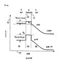
図1は、InPエミッタ/GaAsSbベース/InPコレクタを持つ従来型HBTのエミッタ−ベース接合に適度な順方向電気バイアスを印加した場合のエネルギーバンド図(参照番号11)を示す。縦軸12はエネルギーレベルを示し、横軸14は距離、即ちエミッタ領域22、ベース領域24及びコレクタ領域26をそれぞれに構成する材料の厚さを示している。GaAsSbベースとInPコレクタを持つヘテロ接合バイポーラトランジスタ(HBT)は、図示したようにコレクタ−ベース接合32においてタイプIIのバンド構造を持っている。伝導帯16におけるエネルギー不連続量ΔEcは約0.18eV(エレクトロンボルト)であり、価電子帯18におけるエネルギー不連続量ΔEvは約0.76eVである。基本的に、この接合に対するこのバンド構造は以下の理由から理想的とされる。小さな衝撃エネルギーΔEcが集められた電子に与えられ、そして金属級[metallurgical]ベース(ベース−コレクタ接合32)に大きい価電子帯不連続量ΔEvが作られる。これにより、小さな又は正のコレクタバイアスであってもコレクタ領域26への正孔の注入される量が最小とされる。広いバンドギャップのInPはコレクタ領域26全体にわたって伸びている為、電子雪崩降伏が最少化される。
【0005】
InPには格子整合しているが、GaAsSbとは異なるベース層を持つ他のHBTの場合、これらの利点は提供されない。例えば、同じ構造でInGaAsベースとした場合、金属級ベースにおける大きな価電子帯不連続量ΔEvと、広バンドギャップInPの利点は提供されるものの、電子収集を阻む障壁が生じ、これによりベース中に好ましくない電荷の蓄積が起きる可能性がある。これは装置の周波数応答及び最高電流値を損なってしまう。この障壁を排除するにしても、その為の方法はいずれも金属級コレクタ−ベース接合の大きな価電子帯不連続量ΔEvと広バンドギャップInPの利点を犠牲にするものである。
【0006】
更に、GaAsSbベースとInPエミッタ(図1)を持つHBTであっても、タイプIIのバンド構造に起因した2つの欠点がある。これら2つの欠点は、“q”を電荷、“ΔEc”を伝導帯不連続性、“k”をボルツマン定数、“T”を絶対接合温度とした場合にexp(−qΔEc/kT)であるヘテロ接合における電子密度の不連続性に関係している。ΔEcは約0.18±0.1eVである為、不連続部にわたる電子密度の比率は室温で2x10−5〜5x10−2である。
【0007】
第一の欠点は、低い電流利得である。限界注入レベルを下回る場合、金属級接合(エミッタ−ベース接合28)における界面再結合はエミッタ側接合部の電子密度と界面準位特性に左右される。
【0008】
界面電流密度jinterfaceは、界面エミッタ側の電子密度をnemi tter、界面再結合速度をvinterfaceとした場合、jinterface=qnemittervinterfaceで表される。界面再結合速度vinterfaceは、界面準位による電子捕獲が生じる断面積をσn、電子の熱運動速度をvthermal、単位面積あたりの電子捕獲準位密度をNtraps、界面における空間的な間接放射再結合の比例関係を説明する定数をKs_i_rad、そして界面ベース側の正孔密度をPbaseとした場合、vinterface=σnvthermalNtraps+Ks_i_radPbaseで表される。従って、全体の界面再結合速度は、電子捕獲順位を通過する再結合及び空間的な間接放射再結合によるのである。実際に形成し得る材料界面は電気的に完全とは言えない。例えば、エネルギーギャップ中に空間的局在化状態を作り出す要因となる不純物又は欠陥が界面中に存在することもある。これらの空間的局在化状態の中へと到達した電子又は正孔は移動することが出来ず(伝導帯又は価電子帯中の電子又は正孔は移動可能)、また、これらの空間的局在化状態は価電子帯及び伝導帯の間のポテンシャルエネルギーを持っている。これらの空間的局在化状態は電子及び正孔を交互に捕獲し、これにより再結合経路を提供するのである。これは概念的にショットキー・リード・ホール再結合と似ている。空間的な間接再結合はタイプIIヘテロ接合の一方の側(この事例ではInP側)に局在化された電子と、反対側(この事例ではGaAsSb側)に局在化された正孔との間に生じるバンド間再結合である。この再結合を空間的な間接再結合と呼ぶのは、電子と正孔が古典物理学に基づいて分離される為である。量子物理学によれば、電子及び正孔は完全に局在化されているわけではない。これらはわずかに重なり合う波動関数により表される。従っていくらかの再結合が生じる。これらの作用はいずれも当事者には周知である。
【0009】
注入電流密度jinjectionは、エミッタ−ベース接合のベース側の注入電子密度をnbase、そしてベースを通る電子の速度をvbaseとした場合、jinjection=qnbasevbaseで表される。jinjection/jinterface=vbasenbase/vinterfacenemitterの比は、トランジスタの電流利得の上限を表す。金属接合のいずれかの側の電子密度比により界面再結合速度がexp(qΔEc/kT)で有効に乗算され、電流利得に直接的な影響を及ぼすことになる。
【0010】
GaAsSbベース及びInPエミッタを含むHBTの第二の欠点とは、電流が、電流利得の圧縮が生じるに値にまで低下するという点である。代表的なHBTにおいては、エミッタ−ベース容量を低減する為にエミッタに比較的低濃度のNeが添加される。例えば、エミッタに4−8x1017cm−3の不純物添加を行った場合、ベースへの注入電子密度にNeexp(−qΔEc/kT)の厳格な上限が課せられる。これは図1のInP/GaAsSb/InP型HBTのエミッタ−ベース接合68に、強い順方向バイアスを印加した場合のエネルギーバンド図(参照番号51)である図2に示されている。このバイアス値に近づくと、エミッタ容量が非常に大きくなり、周波数応答が急激に低下する。純粋な拡散輸送では、ベースを通る電子速度(vbase)は代表的なマイクロ波トランジスタにおいて107cm/秒程度である。これにより、電子不連続性がある場合は電流密度20A/cm2〜5x104A/cm2において利得圧縮が生じる。実験結果から得られた値はこの範囲の中でも上限値に近いが、それでもエミッタ帯電周波数gm/(2πCe)を制限することで装置の性能に深刻な限界が設けられる(ここでgmはダイナミックエミッタコンダクタンス、Ceはエミッタ接合容量)。
【0011】
これらの問題は、エネルギーバンドをうまく調整することにより伝導帯不連続量を低減する、或いは排除すれば小さくする又はなくすことが出来る。しかしながらエミッタ又はベースに四元材料を用いることなく、格子整合条件を満たす材料系により、そのようなバンド構造を得ることは、困難或いは不可能ですらある。アルミニウムインジウム砒素燐(AlInAsP)といった四元材料を用いて高品質な膜を成長させることがいかに困難であるかは良く知られている。特に格子整合を得ることが難しく、製造工程においてもエッチング処理が困難となる。他の手法として、GaAsSbよりもわずかに高い伝導帯エネルギーを持つエミッタ材料を用いることが可能である。この手法によると、エミッタ−ベース接合にターンオン電圧を増大させてしまう伝導帯スパイクが生じることになる。しかしながら、電流限界はなくなり、ターンオン電圧に対するスパイクの影響も、スパイク通過に充分なエネルギーを電子に与えようとするかわりに、電子をトンネルさせることにより著しく小さくすることが出来る。これはスパイクによるトンネル通過の作用として知られている。
【0012】
【発明が解決しようとする課題】
従って、当該分野においてはベースにおける伝導帯バンドエネルギーよりも高い伝導帯バンドエネルギーを持つエミッタ材料を含み、かつ既存の技術を用いて容易に製造することが出来るHBTが必要とされているのである。
【0013】
【課題を解決するための手段】
本発明は、GaAsSb/AlInAs界面に望ましい特性を呈するベース−エミッタ接合を持つHBTを提供するものであり、このHBTはGaAsSbベースとAlInAsエミッタとに接触する中間層をエミッタ中に含むことを特徴とする。中間層は実質的な電気透過性を呈するように、充分薄くはあるがAlInAsエミッタをその上で成長させるに足る表面を提供できるような厚さを持っている。実質的に電気透過性の中間層は、GaAsSbベース及びAlInAsエミッタに対して格子整合性を持っているか、或いは見かけ上の格子整合を実現するように仮晶成長される。仮晶層はその格子が成長方向に垂直の2つの次元において基板格子に整合するように引き伸ばされた、或いは圧縮されたものである。
【0014】
以下の説明においては、npn構造のへテロ接合バイポーラトランジスタ(HBT)を例にあげているが、本発明はpnp構造のHBTにも等しく適用することが出来る。
【0015】
【発明の実施の形態】
図3は、本発明に基づいて製造されたHBT100の断面を示す概略図である。HBT100はInP基板101を含み、この上に高濃度のn型不純物を添加したサブコレクタ層102が形成されている。サブコレクタ層102上にはn型InPコレクタ層104が形成される。また、図示したように、サブコレクタ層102の一部分には金属接触部(コンタクト)106が形成されている。
【0016】
InPコレクタ層104上には高濃度のp型不純物を添加したGaAsSbベース層108が形成されており、このベース層108の一部分には図示したように金属接触112が設けられている。本発明の一実施例によれば、中間層110はベース層108上に形成される。薄い中間層110はエミッタ−ベース接合部に狭幅量子井戸を形成するものである。中間層110はまた、GaAsSbベース層108及びAlInAsエミッタ114の格子定数に一致する格子定数を持っている。
【0017】
中間層110として例えばInPを、GaAsSbベース層108及びAlInAsエミッタ114と格子整合するように成長させることが出来る。この場合、中間層110のバルク格子定数がGaAsSbベース材料及びAlInAsエミッタ材料の格子定数に合致する。かわりに、中間層110に格子不整合材料を用いることも出来るが、この場合は厚さを充分に薄く設定し、その格子パラメータがGaAsSbベース層108及びAlInAsエミッタ114の格子パラメータに一致するように仮晶成長させる。例えば、中間層110をInxGa1−xP(xは1に近づく値ではあるが、等しくはならない)で成膜する場合、中間層110は、GaAsSbベース層108及びAlInAsエミッタ114の格子定数に一致した格子定数を持つことになるように仮晶成長により形成される。
【0018】
薄い中間層を仮晶成長させると「歪み」を持つに至り、その格子定数は基板材料の格子定数に一致することになる。当事者には周知のように、仮晶層中の格子定数は成長方向に垂直な2つの次元において基板格子と一致するように引っ張られ、或いは圧縮されるのである。成長方向における格子パラメータは全く異なるが、仮晶表面が呈する格子定数は、成膜中に供給される構成原子にとっては格子整合表面なのである。従って、薄い仮晶層を中間層110として用いることは物質的に、完全に格子整合した中間層110を用いることに極めて近いことである。以下の説明においては、便宜上、中間層110がInPから形成されたものであると仮定している。しかしながら、中間層110の形成にはGaAsSbベース材料及びAlInAsエミッタ材料の格子定数に整合するバルク格子定数を持つ他の材料を用いることも可能である。同様に、InxGa1−xP(xは1に近づく値ではあるが、等しくはならない)以外の仮晶成長中間層とすることも出来る。
【0019】
エミッタ114は中間層110上に形成された、低濃度のn型不純物を添加したAlInAs層116を含む。AlInAs層116の上にはこれより高い濃度のn型不純物を添加したAlInAs層118が、そしてAlInAs層118上には高濃度のn型不純物を添加したInGaAs層120が形成されている。これらの2層118及び120はエミッタ114にオーム接触を形成するものであり、これによりエミッタ114上に金属接触122を設けることが出来る。サブコレクタ層102、コレクタ層104、ベース層108、中間層110及びエミッタ114は、例えば分子線エピタキシー(MBE)により成長させることが出来るが、方法はこれに限られない。
【0020】
上述したように、界面再結合の速度は一部、金属級エミッタ−ベース接合部に存在する準位数Ntrapsに依存する。簡単な方法で所定のヘテロ接合の準位密度を予測することは出来ないが、これを最少化することは望まれる。従って、GaAsSbベース層108と中間層110により形成されるInP/GaAsSbヘテロ接合は、この材料系により良好な利得を持つHBTを形成することが出来ることから、許容され得る範囲の低い順位密度を持っていると見られる。AlInAs/GaAsSb接合でこれを実現することは難しい。従って、InPの中間層110を用いて構成した構造は、InP/GaAsSbエミッタ−ベース構造の低準位密度特性を示しつつ、AlInAs/GaAsSbエミッタ−ベース構造における望ましいバンド構造を持っているかのような挙動をも呈するのである。これは多くのIII−V化合物中の導電電子の量子的性質と軽い実効質量、そして特にInPにおいては、界面準位の局在化性質を利用して実現したものである。この結果得られる構造は、形成が容易で、AlInAs/GaAsSb/InP構造を持つHBTの望ましい電子輸送特性と、InP/GaAsSb/InP構造を持つHBTに等しい、あるいはこれよりも高い電流利得を有するのである。
【0021】
図4は、図3に示したHBTのエネルギーバンド150を示すグラフである。InP量子井戸178がAlInAsエミッタ領域162とGaAsSbベース領域164との間に2つのヘテロ接合を形成している。一方のヘテロ接合はInP/GaAsSb界面168に形成され、もう一方はInP/AlInAs界面188に形成されている。InP量子井戸178は、エネルギー不連続量が伝導帯においては0.07eV(ΔEc=0.25−0.18)、価電子帯においては0.60eV(ΔEv=0.76−0.16)の有効なヘテロ接合をGaAsSbベース領域164とAlInAsエミッタ領域162の間に形成しているのである。この有効なへテロ接合の位置は、価電子帯においてはInP/GaAsSb界面168にあるが、伝導帯においてはAlInAs/InP界面188にある。GaAsSbベース領域164とInPコレクタ領域166との間のGaAsSb/InP界面172に形成されるヘテロ接合は、伝導帯の不連続量ΔEcが0.18eV、そして価電子帯の不連続量ΔEvが0.76eVである。
【0022】
先にも述べた通り、AlInAs/GaAsSb型HBTに望ましいこれらの特性は、材料のバンド構造から得られるものである。全般的な規則として、バンド構造はいかなる層が介在してもこれとは無関係であると考えられる。従って、InP中間層110をGaAsSbベース層108とAlInAsエミッタ114との間に設けたとしても、AlInAsエミッタ領域162及びGaAsSbベース領域164間のバンド構造に実質的な影響を与えることはない。しかしながら、図4に示したように、InP中間層110はAlInAsエミッタ領域162とGaAsSb領域164との間の金属級接合においてInP量子井戸178を作る。電子がこの井戸に捕獲された場合、これらの電子は好ましくないエミッタ再結合電流に寄与する傾向がある。しかしながら、本発明の一態様に基づいて電子の量子機械的特性を考慮することにより、電子密度に殆ど影響を与えることがないようにInP量子井戸178を作ることが出来る。以下にも説明するが、要するにInP量子井戸178が電気透過性となるように設計するのである。
【0023】
図5はInP量子井戸のサブバンドエネルギーを示すグラフ190である。縦軸はサブバンドエネルギーをeV単位で表し、横軸は量子井戸幅をnm単位で表している。トレース192は、一方の側に0.18eVの障壁、他方の側に0.25eVの障壁がある非対称四角形井戸ポテンシャルにおける最低エネルギー状態の固有エネルギーの計算値を表している。電子は0.077moの実効質量(moは自由電子質量)を持っているものと仮定する。これらの値は、図3及び図4に関連して説明した格子が整合するAlInAs及びGaAsSb間に閉じ込められたInP量子井戸としては適切な値である。
【0024】
説明の便宜上、ここでは図5に示したエネルギーを「最低サブバンドエネルギー」と呼び、それは1次元(1D)計算結果を表すものである。しかしながら、実世界は3次元(3D)である。従って、図示の1D量子井戸は1次元においては電子を閉じ込めるが、他の2つの次元における移動は自由である。図5のエネルギーを「最低サブバンドエネルギー」Esbと呼ぶのは、3Dである現実において1Dの量子井戸を明確に説明する為である。このエネルギーは1D固有エネルギーと同じである。
【0025】
約2nm未満の厚さを持つ量子井戸(トレース192のうち、部分196に示されるように)においては、電子エネルギーの熱的スミアによって電子総数の過多が無視出来る大きさにまで小さくなる程、最低状態のエネルギーがGaAsSbベースのバンドエネルギーに近い。電子を界面に対して垂直方向には閉じ込めるが他の2つの次元においては自由とする単一のサブバンドを持つ量子井戸は、実効質量が0.77moの場合、約3.2x1013cm−2eV−1の一定密度の状態Nssを持つ。注入面積電子密度nbase−sheet=WbaseNcexp(−q(Ec−Ef)/kT)を量子井戸中に拘束された電子の単位面積あたり密度と比較することができ;nss=(kT/q)Nssexp(−q(Ec−Ef)/kT)exp(q((Ec−Esb)/kT)(1−exp(−q(Ec−Esb)/kT)、即ちnss/nbase−sheet=(Ec−Esb)Nssexp(q(Ec−Esb)/kT)/WbaseNc;従って伝導帯エネルギー未満の拘束状態kT/qでは、nssはベース中の注入シート電子密度と同程度であり、バンド間再結合及び界面再結合を許容範囲の分量だけ増加する。
【0026】
更に、トレース192の部分194に示される通り、厚さ約1.1nm未満の量子井戸については、井戸に付随して生じる拘束状態が無い。これは障壁の非対称性によるものであり、中間層が薄ければ、たとえ零度の温度でもInP中の電子密度は過多とならず、よってエミッタ再結合電流への好ましくない影響は無くなる。エミッタ領域162とベース領域164の間にある薄い中間層(図4)は、電子密度に影響を与えることも、電子輸送の障壁を形成することも無い為、基本的に電気透過性である。このようにAlInAsエミッタとGaAsSbベースとの間に設けられた薄いInP中間層によりAlInAsエミッタ及びGaAsSbベースの両方に格子が整合した表面が提供されると共に、AlInAsエミッタを採用したことでHBTに与えられる優れた性能を維持することが可能となるのである。GaAsSbベース及びInP量子井戸間の格子整合、そしてInP量子井戸及びAlInAsエミッタ間の格子整合は、格子整合材料により直接的に、或いは格子不整合材料の薄い層を中間層として仮晶成長させることにより実現することが出来る。
【0027】
ここで図3に戻って説明するが、エミッタ114及びベース層108間にInP中間層110を挿入することによる利得への悪影響は全く無いか、あってもわずかであるが、良い特質は付加される。AlInAs/GaAsSb界面は、AlInAs/InP界面及びInP/GaAsSb界面に置き換えられている。先にも説明したように、AlInAsエミッタ、又はベースの伝導帯エネルギー以上の伝導帯エネルギーを持つエミッタを採用することにより、空間的に間接的なバンド間再結合が排除される。これは、先に述べたように薄いInP層には拘束状態が存在しない為、薄いInP中間層を持つエミッタにおいても同じである。残った界面再結合メカニズムは界面準位によるものであり、再結合速度vinterface=σnvthermalNtrapsを如何に制御するかという問題になる。AlInAsエミッタ114の場合、重要なのは面積密度Ntraps及び電子を捕獲する準位の断面のみであることは明らかである。
【0028】
図4に戻って説明するが、エミッタ−ベース接合付近にはAlInAs/InP界面188とInP/GaAsSb界面168の2つの界面が存在している。留意すべきは、ベース中の正孔はInP/GaAsSb界面168には近づくが、AlInAs/InP界面188に対してはInP中間層110(図3)が作る0.76eV障壁をトンネルしなければ到達することが出来ないという点である。界面再結合に寄与するAlInAs/InP界面188及びInP/GaAsSb界面168のポテンシャルを考慮しなければならない。再結合は電子の捕獲と正孔の捕獲が交互に起きることにより生じる為、最初に大量の正孔の供給があるかどうかについて考える。ここで考えられるのは、正孔はAlInAs/InP界面188には直接的に流入することが出来ない為、界面再結合に寄与する要因からAlInAs/InP界面188をほぼ完全に外すことが出来るという点である。正孔がこの界面に到達するには、InPによる0.76eVの障壁をトンネルするしかない。トンネルする可能性は正孔が軽いか重いかによって大幅に異なり、障壁幅に依存するものであるが、AlInAs/InP界面188に形成されるヘテロ接合の作用は一桁以上小さくすることが出来る。
【0029】
従って、界面準位再結合速度を判定する上で重要な界面はInP/GaAsSb界面168であると考えられる。この界面168に形成されるヘテロ接合は、良好な特性を持つように成長させることが可能であり、AlInAs/GaAsSb界面よりもInP/GaAsSb界面の方が優れていることは実験結果も支持している。更に、AlInAs/InP界面とInP/GaAsSb界面の組み合わせは、AlInAs/GaAsSb界面のみの場合よりも良好な電流利得を示す。
【0030】
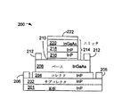
図6は、図3に示したHBT100とは異なる実施例を示す断面図である。HBT200はInP基板201を含み、この上に高濃度のn型不純物を添加したサブコレクタ層202が形成されている。サブコレクタ層202上にはn型InPコレクタ層204が形成されている。サブコレクタ層202の一部分には図示の通り金属接触部206が設けられている。
【0031】
図3に基づいて説明したものとは異なり、InPコレクタ層204上にはp型InGaAsベース層208が形成され、ベース層208の一部分には図示の通り金属接触部212が設けられている。本発明のこの態様によれば、GaAsSbからなる中間層210がInGaAsベース層208上に設けられる。以下にも図7に関連して説明するが、薄いGaAsSb中間層210はエミッタ−ベース接合に狭幅量子井戸を形成するが、本実施例においては、量子井戸は伝導帯ではなく価電子帯中に形成される。GaAsSbの中間層210の格子定数はInGaAsベース層208及びInPエミッタ214の格子定数に一致している。GaAsSbのような材料を用いることにより、InGaAsベース層208及びInPエミッタ214に格子整合する中間層210を形成することが出来る。かわりに格子不整合材料を使って中間層210を形成することも出来るが、この場合は層厚を充分に薄く設定して仮晶成長させることによりその格子パラメータをInGaAsベース層208及びInPエミッタ214の格子パラメータに一致させる。先にも説明したように、このように薄い中間層を仮晶成長させて「歪ませる」ことにより基板材料の格子定数に整合させることが出来る。
【0032】
エミッタ214は、GaAsSbからなる中間層210上に形成された低濃度のn型InP層216を含む。そしてこれよりも高い濃度のn型不純物を添加したInP層218がInP層216上に、そして高濃度のn型InGaAs層220がInP層218上に形成される。これらの2つの層218及び220は、エミッタ214にオーム接触を形成し、これによりエミッタ214上に金属接触222を設けることが可能となる。サブコレクタ層202、コレクタ層204、ベース層208、中間層210及びエミッタ214は、例えば分子線エピタキシー(MBE)によって形成することが出来るが、方法はこれに限られない。
【0033】
図7は、図6に示したHBTのエネルギーバンド250のグラフである。GaAsSb量子井戸278はInPエミッタ領域262とInGaAsベース領域264との間に2つのヘテロ接合を形成する。一方のヘテロ接合はInP/GaAsSb界面268に、そしてもう一方のヘテロ接合はGaAsSb/InGaAs界面288に形成される。GaAsSb量子井戸278は、InGaAsベース領域264及びInPエミッタ領域262間に伝導帯におけるエネルギー不連続量が0.23eV(ΔEc=0.41−0.18)、そして価電子帯におけるエネルギー不連続量が0.34eV(ΔEv=0.76−0.42)の有効なヘテロ接合を形成している。この有効なヘテロ接合の位置は、価電子帯においてはInP/GaAsSb界面268にあるが、伝導帯においてはGaAsSb/InGaAs界面288にある。この図から明らかなように、図6のInPエミッタ214とInGaAsベース層208との間にGaAsSb中間層210を設けた場合、エミッタ−ベース接合の価電子帯中に非対称量子井戸278が形成されるのである。
【0034】
以上は、特にInPコレクタ、AlInAsエミッタ及びGaAsSbベースを含み、エミッタ及びベース間にInP中間層を形成したHBT、そしてInPコレクタ、InPエミッタ及びInGaAsベースを含み、エミッタ及びベース間にGaAsSb中間層を形成したHBTに関して説明したものであるが、本発明は、異なるバンド構造(例えば、InP/GaAsSb及びInP/AlInAsから成る)を使って界面の望ましい物理化学的構成を保ちつつ、望ましいバンド構造(例えば、AlInAs及びGaAsSb間のタイプI構成)を維持する構成であると解釈することが出来る。そしてこれは薄いポテンシャル井戸の量子機械的特性を利用することにより実現される。
【0035】
当事者には明らかなように、先に説明した本発明の好適な実施の形態には本発明の原理から著しく離れることなく様々な変更や改変を加えることが出来る。例えば、本発明の概念は、npn型HBT及びpnp型HBTのいずれにとっても有益なものである。これらの変更及び改変形態は、添付請求項に定義された本発明の範囲に全て含まれるものである。
【0036】
本発明を上述の実施形態に即して説明すると、本発明は、コレクタ(104)と、コレクタ(104)上に位置するベース(108)と、そしてベース(108)上に位置するエミッタ(114)とを含むヘテロ接合バイポーラトランジスタ(HBT)(100)であって、エミッタ(114)がベース(108)に接触する中間層(110)を含み、中間層(110)がベース(108)及びエミッタ(114)に対して実質的に電気透過性であり、中間層(110)の格子定数がベース(108)及びエミッタ(114)の格子定数に一致していることを特徴とするヘテロ接合バイポーラトランジスタ(100)を提供する。
【0037】
好ましくは、コレクタ(104)がインジウム燐(InP)であり、ベース(108)がガリウム砒素アンチモン(GaAsSb)であり、そしてエミッタ(114)がInPからなる中間層(110)及びアルミニウムインジウム砒素(AlInAs)からなる層(116)を含む。
【0038】
好ましくは、InPからなる中間層(110)の厚さが2nm未満である。
【0039】
好ましくは、InPからなる中間層(110)の厚さが1.2nm未満である。
【0040】
好ましくは、中間層(110)が仮晶成長させたものである。
【0041】
好ましくは、中間層(110)の材料が、ベースの材料及びエミッタの材料の格子定数に一致するバルク格子定数を持つものである。
【0042】
更に、本発明は、ヘテロ接合バイポーラトランジスタ(100)の製造方法であって、コレクタ(104)を形成するステップと、コレクタ(104)上にベース(108)を形成するステップと、そしてベース(108)上にエミッタ(114)を形成するステップとを含み、エミッタ(114)がベース(108)に接触する中間層(110)を含み、中間層(110)がベース(108)及びエミッタ(114)に対して実質的に電気透過性であり、中間層(110)の格子定数がベース(108)及びエミッタ(114)の格子定数に一致していることを特徴とする方法を提供する。
【0043】
好ましくは、コレクタ(104)がインジウム燐(InP)を用いて形成され、ベース(108)がガリウム砒素アンチモン(GaAsSb)を用いて形成され、そしてエミッタ(114)がInPからなる中間層(110)及びアルミニウムインジウム砒素(AlInAs)からなる層(116)により形成される。
【0044】
好ましくは、InPからなる中間層(110)の厚さが2nm未満である。
【0045】
好ましくは、InPからなる中間層(110)の厚さが1.1nm未満である。
【図面の簡単な説明】
【図1】InPエミッタ/GaAsSbベース/InPコレクタ構造を持つ従来型HBTのエミッタ−ベース接合に適度な順方向バイアスを印加した場合のエネルギーバンドを示すグラフである。
【図2】図1に示したInPエミッタ/GaAsSbベース/InPコレクタ構造を持つHBTのエミッタ−ベース接合に強い順方向バイアスを印加した場合のエネルギーバンドを示すグラフである。
【図3】本発明に基づいて製作したHBTの断面図である。
【図4】図3に示したHBTのエネルギーバンドを示すグラフである。
【図5】InP量子井戸のサブバンドエネルギーを示すグラフである。
【図6】図3に示したHBTの他の実施形態の断面図である。
【図7】図6に示したHBTのエネルギーバンドを示すグラフである。
【符号の説明】
100 ヘテロ接合バイポーラトランジスタ(HBT)
104 コレクタ
108 ベース
110 中間層
114 エミッタ
116 エミッタのAlInAs層[0001]
[Technical field to which the invention belongs]
The present invention relates generally to transistors, and more specifically to heterojunction bipolar transistors (HBTs) having improved emitter-base junctions.
[0002]
[Prior art]
In applications where high speed switching and high frequency operation are desired, npn heterojunction bipolar transistors (HBTs) have been used in the past. The emitter in the HBT has a larger band gap than the base hand gap, thereby forming an energy barrier in the valence band of the emitter-base junction that inhibits undesired hole flow from the base region to the emitter region. Is done. This configuration increases the emitter injection efficiency, current gain and operating frequency of the HBT.
[0003]
The first generation commercial HBT was based on a gallium arsenide (GaAs) substrate and a semiconductor material whose crystal lattice matched to this GaAs. In subsequent generations, there are many HBTs made of an indium phosphide (InP) substrate and a semiconductor material whose crystal lattice matches that of InP. Such an HBT is usually composed of an indium gallium arsenide (InGaAs) material system or a gallium arsenide antimony (GaAsSb) material system, and a collector and an emitter formed of, for example, InP, aluminum indium arsenide (AlInAs), or InGaAs. It is. An HBT having a base material of GaAsSb and an emitter material of AlInAs is superior to an HBT having a base material of GaAsSb and an emitter material of InP. For example, the energy band structure of the conduction band between AlInAs and GaAsSb (emitter-base) provides certain advantages, such as allowing operation at higher current densities, ie, operation at higher frequencies. Unfortunately, however, it is difficult to form a good AlInAs / GaAsSb interface.
[0004]
FIG. 1 shows an energy band diagram (reference number 11) when a moderate forward electrical bias is applied to the emitter-base junction of a conventional HBT having an InP emitter / GaAsSb base / InP collector. The
[0005]
Other HBTs that are lattice matched to InP but have a different base layer than GaAsSb do not provide these advantages. For example, in the case of using InGaAs base with the same structure, a large valence band discontinuity ΔE in the metal class basevWhile providing the benefits of wide bandgap InP, it creates a barrier that prevents electron collection, which can lead to unwanted charge accumulation in the base. This impairs the frequency response and maximum current value of the device. Even if this barrier is eliminated, all of the methods for this purpose have a large valence band discontinuity ΔE in the metal class collector-base junction.vAnd sacrifice the advantages of wide band gap InP.
[0006]
Furthermore, even an HBT having a GaAsSb base and an InP emitter (FIG. 1) has two drawbacks due to the type II band structure. These two drawbacks are that “q” is charged, “ΔEcExp (−qΔE) where “is the conduction band discontinuity,“ k ”is the Boltzmann constant, and“ T ”is the absolute junction temperature.c/ KT) related to the discontinuity of the electron density at the heterojunction. ΔEcIs about 0.18 ± 0.1 eV, so the ratio of the electron density over the discontinuity is 2 × 10 at room temperature.-5~ 5x10⁻²It is.
[0007]
The first drawback is low current gain. When below the critical injection level, the interface recombination in the metal class junction (emitter-base junction 28) depends on the electron density and interface state characteristics of the emitter side junction.
[0008]
Interface current density jinterfaceIs the electron density on the interface emitter side, nemi tter, Interface recombination velocity vinterfaceJinterface= QnemittervinterfaceIt is represented by Interface recombination velocity vinterfaceIs the cross-sectional area where electron capture by interface states occurs σn, Vthermal, The density of electron capture levels per unit area is Ntraps, A constant describing the proportional relationship of spatial indirect radiative recombination at the interfaces_i_rad, And the hole density on the interface base side is PbaseVinterface= ΣnvthermalNtraps+ Ks_i_radPbaseIt is represented by Thus, the overall interface recombination velocity is due to recombination through the electron capture order and spatial indirect radiative recombination. The material interface that can actually be formed is not electrically perfect. For example, there may be impurities or defects in the interface that cause a spatially localized state in the energy gap. Electrons or holes that have reached these spatially localized states cannot move (electrons or holes in the conduction band or valence band can move), and these spatial stations The localized state has potential energy between the valence band and the conduction band. These spatially localized states capture electrons and holes alternately, thereby providing a recombination path. This is conceptually similar to Schottky lead hole recombination. Spatial indirect recombination is between an electron localized on one side of the type II heterojunction (in this case, the InP side) and a hole localized on the other side (in this case, the GaAsSb side). Interband recombination that occurs in between. This recombination is called spatial indirect recombination because electrons and holes are separated based on classical physics. According to quantum physics, electrons and holes are not fully localized. These are represented by slightly overlapping wave functions. Therefore, some recombination occurs. Both of these actions are well known to those skilled in the art.
[0009]
Injection current density jinjectionIs the injected electron density on the base side of the emitter-base junction nbase, And the velocity of electrons through the base vbaseJinjection= QnbasevbaseIt is represented by jinjection/ Jinterface= Vbasenbase/ VinterfacenemitterThis ratio represents the upper limit of the current gain of the transistor. The electron density ratio on either side of the metal junction effectively multiplies the interface recombination rate by exp (qΔEc / kT) and directly affects the current gain.
[0010]
A second disadvantage of HBTs that include GaAsSb bases and InP emitters is that the current drops to a value when current gain compression occurs. In a typical HBT, the emitter has a relatively low concentration of N to reduce the emitter-base capacitance.eIs added. For example, 4-8x10 for the emitter17cm-3Is added to the base, the density of electrons injected into the base is N.eA strict upper limit of exp (−qΔEc / kT) is imposed. This is shown in FIG. 2, which is an energy band diagram (reference number 51) when a strong forward bias is applied to the emitter-base junction 68 of the InP / GaAsSb / InP type HBT of FIG. As this bias value is approached, the emitter capacitance becomes very large and the frequency response decreases rapidly. In pure diffusion transport, the electron velocity through the base (vbase) Is 10 for typical microwave transistors.7It is about cm / second. Thus, when there is an electron discontinuity, the current density is 20 A / cm.2~ 5x10⁴A / cm2Gain compression occurs. The value obtained from the experimental results is close to the upper limit value in this range, but the emitter charging frequency gm/ (2πCe) Limits the performance of the device (where gmIs the dynamic emitter conductance, CeIs the emitter junction capacitance.
[0011]
These problems can be reduced or eliminated if the conduction band discontinuity is reduced or eliminated by well adjusting the energy band. However, it is difficult or even impossible to obtain such a band structure by using a material system that satisfies the lattice matching condition without using a quaternary material for the emitter or base. It is well known how difficult it is to grow high quality films using quaternary materials such as aluminum indium arsenide phosphorus (AlInAsP). In particular, it is difficult to obtain lattice matching, and the etching process becomes difficult in the manufacturing process. As another approach, an emitter material having a slightly higher conduction band energy than GaAsSb can be used. This approach results in a conduction band spike that increases the turn-on voltage at the emitter-base junction. However, the current limit is eliminated and the effect of the spike on the turn-on voltage can be significantly reduced by tunneling the electrons instead of trying to give the electrons enough energy to pass the spikes. This is known as the effect of passing through a tunnel due to spikes.
[0012]
[Problems to be solved by the invention]
Accordingly, there is a need in the art for an HBT that includes an emitter material having a conduction band energy higher than the conduction band energy in the base and that can be easily manufactured using existing techniques.
[0013]
[Means for Solving the Problems]
The present invention provides an HBT having a base-emitter junction exhibiting desirable characteristics at the GaAsSb / AlInAs interface, the HBT including an intermediate layer in contact with the GaAsSb base and the AlInAs emitter in the emitter. To do. The intermediate layer has a thickness that is thin enough to provide substantial electrical permeability, but can provide a surface sufficient to grow an AlInAs emitter thereon. The substantially electrically transmissive intermediate layer is lattice matched to the GaAsSb base and the AlInAs emitter, or is pseudocrystal grown to achieve an apparent lattice match. The pseudomorphic layer is stretched or compressed so that its lattice matches the substrate lattice in two dimensions perpendicular to the growth direction.
[0014]
In the following description, an npn-structure heterojunction bipolar transistor (HBT) is taken as an example, but the present invention is equally applicable to a pnp-structure HBT.
[0015]
DETAILED DESCRIPTION OF THE INVENTION
FIG. 3 is a schematic view showing a cross section of the
[0016]
On the
[0017]
For example, InP can be grown as the
[0018]
When a thin intermediate layer is grown as a pseudocrystal, it has “strain”, and its lattice constant coincides with the lattice constant of the substrate material. As is well known to those skilled in the art, the lattice constant in the pseudocrystalline layer is pulled or compressed to coincide with the substrate lattice in two dimensions perpendicular to the growth direction. Although the lattice parameters in the growth direction are completely different, the lattice constant exhibited by the pseudocrystal surface is a lattice-matched surface for the constituent atoms supplied during film formation. Therefore, using a thin pseudocrystalline layer as the
[0019]
The
[0020]
As mentioned above, the interface recombination rate is partially due to the number of levels N present at the metal-class emitter-base junction.trapsDepends on. Although it is not possible to predict the level density of a given heterojunction by a simple method, it is desirable to minimize this. Therefore, the InP / GaAsSb heterojunction formed by the
[0021]
FIG. 4 is a graph showing the
[0022]
As previously mentioned, these desirable properties for AlInAs / GaAsSb type HBTs are obtained from the band structure of the material. As a general rule, the band structure is considered independent of any layer. Therefore, even if the InP
[0023]
FIG. 5 is a
[0024]
For convenience of explanation, the energy shown in FIG. 5 is referred to herein as “lowest subband energy”, which represents a one-dimensional (1D) calculation result. However, the real world is three-dimensional (3D). Thus, the illustrated 1D quantum well confines electrons in one dimension, but is free to move in the other two dimensions. The energy shown in FIG.sbThis is to clearly describe a 1D quantum well in a 3D reality. This energy is the same as the 1D intrinsic energy.
[0025]
In quantum wells having a thickness of less than about 2 nm (as shown in
[0026]
Further, as shown in
[0027]
Here, referring back to FIG. 3, there is no adverse effect on the gain due to the insertion of the InP
[0028]
Referring back to FIG. 4, there are two interfaces, an AlInAs /
[0029]
Therefore, it is considered that the interface important for determining the interface state recombination velocity is the InP /
[0030]
FIG. 6 is a cross-sectional view showing an embodiment different from
[0031]
Unlike what has been described with reference to FIG. 3, a p-type
[0032]
The
[0033]
FIG. 7 is a graph of the
[0034]
The above includes an HBT including an InP collector, an AlInAs emitter and a GaAsSb base, and an InP intermediate layer formed between the emitter and the base, and an GaAsSb intermediate layer formed between the emitter and the base, including an InP collector, InP emitter and InGaAs base. Although the present invention has been described with respect to HBTs, the present invention uses different band structures (eg, composed of InP / GaAsSb and InP / AlInAs) while maintaining the desired physicochemical composition of the interface (eg, This can be interpreted as a configuration that maintains a type I configuration between AlInAs and GaAsSb. This is achieved by taking advantage of the quantum mechanical properties of thin potential wells.
[0035]
It will be apparent to those skilled in the art that various changes and modifications can be made to the preferred embodiment of the present invention described above without departing significantly from the principles of the present invention. For example, the concept of the present invention is useful for both npn-type HBTs and pnp-type HBTs. These changes and modifications are all within the scope of the invention as defined in the appended claims.
[0036]
The present invention will be described with reference to the above-described embodiments. The present invention includes a collector (104), a base (108) located on the collector (104), and an emitter (114) located on the base (108). A heterojunction bipolar transistor (HBT) (100) including an intermediate layer (110) in which the emitter (114) contacts the base (108), and the intermediate layer (110) includes the base (108) and the emitter Heterojunction bipolar transistor characterized in that it is substantially electrically transmissive with respect to (114) and the lattice constant of the intermediate layer (110) matches the lattice constant of the base (108) and emitter (114) (100) is provided.
[0037]
Preferably, the collector (104) is indium phosphide (InP), the base (108) is gallium arsenide antimony (GaAsSb), and the emitter (114) is InP made of InP and aluminum indium arsenide (AlInAs). ).
[0038]
Preferably, the thickness of the intermediate layer (110) made of InP is less than 2 nm.
[0039]
Preferably, the thickness of the intermediate layer (110) made of InP is less than 1.2 nm.
[0040]
Preferably, the intermediate layer (110) is grown by a pseudo crystal.
[0041]
Preferably, the material of the intermediate layer (110) has a bulk lattice constant that matches the lattice constant of the base material and the emitter material.
[0042]
The present invention further relates to a method of manufacturing a heterojunction bipolar transistor (100), comprising the steps of forming a collector (104), forming a base (108) on the collector (104), and a base (108). Forming an emitter (114) on the intermediate layer (110), wherein the emitter (114) contacts the base (108), and the intermediate layer (110) includes the base (108) and the emitter (114). The method is characterized in that the lattice constant of the intermediate layer (110) is substantially the same as that of the base (108) and the emitter (114).
[0043]
Preferably, the collector (104) is formed using indium phosphide (InP), the base (108) is formed using gallium arsenide antimony (GaAsSb), and the emitter (114) is an intermediate layer (110) made of InP. And a layer (116) made of aluminum indium arsenide (AlInAs).
[0044]
Preferably, the thickness of the intermediate layer (110) made of InP is less than 2 nm.
[0045]
Preferably, the thickness of the intermediate layer (110) made of InP is less than 1.1 nm.
[Brief description of the drawings]
FIG. 1 is a graph showing an energy band when a moderate forward bias is applied to an emitter-base junction of a conventional HBT having an InP emitter / GaAsSb base / InP collector structure.
2 is a graph showing an energy band when a strong forward bias is applied to the emitter-base junction of the HBT having the InP emitter / GaAsSb base / InP collector structure shown in FIG.
FIG. 3 is a cross-sectional view of an HBT manufactured according to the present invention.
4 is a graph showing an energy band of the HBT shown in FIG.
FIG. 5 is a graph showing the subband energy of an InP quantum well.
6 is a cross-sectional view of another embodiment of the HBT shown in FIG. 3. FIG.
7 is a graph showing an energy band of the HBT shown in FIG.
[Explanation of symbols]
100 Heterojunction Bipolar Transistor (HBT)
104 collector
108 base
110 Middle layer
114 emitter
116 AlInAs layer of emitter
Claims (4)
コレクタを形成するステップと、
前記コレクタ上にベースを形成するステップと、
前記ベース上にエミッタを形成するステップとを含み、
前記エミッタが前記ベースに接触する中間層を含み、前記中間層が前記ベース及び前記エミッタに対して実質的に電気透過性であり、前記中間層の格子定数が前記ベース及び前記エミッタの格子定数に一致し、前記コレクタはインジウム燐(InP)であり、前記ベースはガリウム砒素アンチモン(GaAsSb)であり、前記エミッタはInPの中間層とアルミニウムインジウム砒素(AlInAs)の層を含み、前記InPの中間層が、前記エミッタと前記ベースとの間に量子井戸を形成するようにすることを特徴とする方法。A method of manufacturing a heterojunction bipolar transistor, comprising:
Forming a collector;
Forming a base on the collector;
Forming an emitter on the base;
The emitter includes an intermediate layer in contact with the base, the intermediate layer is substantially electrically transmissive to the base and the emitter, and the lattice constant of the intermediate layer is equal to the lattice constant of the base and the emitter. The collector is indium phosphide (InP), the base is gallium arsenide antimony (GaAsSb), the emitter includes an InP intermediate layer and an aluminum indium arsenide (AlInAs) layer, and the InP intermediate layer Forming a quantum well between the emitter and the base .
Applications Claiming Priority (2)
| Application Number | Priority Date | Filing Date | Title |
|---|---|---|---|
| US796180 | 2001-02-27 | ||
| US09/796,180 US6696710B2 (en) | 2001-02-27 | 2001-02-27 | Heterojunction bipolar transistor (HBT) having an improved emitter-base junction |
Publications (3)
| Publication Number | Publication Date |
|---|---|
| JP2002270615A JP2002270615A (en) | 2002-09-20 |
| JP2002270615A5 JP2002270615A5 (en) | 2005-08-25 |
| JP3935372B2 true JP3935372B2 (en) | 2007-06-20 |
Family
ID=25167535
Family Applications (1)
| Application Number | Title | Priority Date | Filing Date |
|---|---|---|---|
| JP2002049395A Expired - Lifetime JP3935372B2 (en) | 2001-02-27 | 2002-02-26 | Heterojunction bipolar transistor with improved emitter-base junction and method of manufacturing the same |
Country Status (3)
| Country | Link |
|---|---|
| US (1) | US6696710B2 (en) |
| EP (1) | EP1235278A3 (en) |
| JP (1) | JP3935372B2 (en) |
Families Citing this family (13)
| Publication number | Priority date | Publication date | Assignee | Title |
|---|---|---|---|---|
| WO2003009396A2 (en) * | 2001-07-20 | 2003-01-30 | Microlink Devices, Inc. | Algaas or ingap low turn-on voltage gaas-based heterojunction bipolar transistor |
| US6822274B2 (en) * | 2003-02-03 | 2004-11-23 | Agilent Technologies, Inc. | Heterojunction semiconductor device having an intermediate layer for providing an improved junction |
| US6960820B2 (en) | 2003-07-01 | 2005-11-01 | International Business Machines Corporation | Bipolar transistor self-alignment with raised extrinsic base extension and methods of forming same |
| US7242038B2 (en) | 2004-07-01 | 2007-07-10 | Nippon Telegraph And Telephone Corporation | Heterojunction bipolar transistor |
| US7297589B2 (en) * | 2005-04-08 | 2007-11-20 | The Board Of Trustees Of The University Of Illinois | Transistor device and method |
| US7651919B2 (en) * | 2005-11-04 | 2010-01-26 | Atmel Corporation | Bandgap and recombination engineered emitter layers for SiGe HBT performance optimization |
| US20070102729A1 (en) * | 2005-11-04 | 2007-05-10 | Enicks Darwin G | Method and system for providing a heterojunction bipolar transistor having SiGe extensions |
| US7300849B2 (en) * | 2005-11-04 | 2007-11-27 | Atmel Corporation | Bandgap engineered mono-crystalline silicon cap layers for SiGe HBT performance enhancement |
| US7439558B2 (en) | 2005-11-04 | 2008-10-21 | Atmel Corporation | Method and system for controlled oxygen incorporation in compound semiconductor films for device performance enhancement |
| US8716096B2 (en) | 2011-12-13 | 2014-05-06 | International Business Machines Corporation | Self-aligned emitter-base in advanced BiCMOS technology |
| CN102646703B (en) * | 2012-05-07 | 2014-12-10 | 中国电子科技集团公司第五十五研究所 | Epitaxial structure of single crystal indium phosphide (InP) group compound semiconductor film |
| CN103021847B (en) * | 2012-11-29 | 2015-03-25 | 中国电子科技集团公司第五十五研究所 | Method for realizing gallium-arsenic-antimony double-heterojunction bipolar transistor base electrode metallization |
| US11935969B2 (en) * | 2019-11-18 | 2024-03-19 | Epistar Corporation | Photodetector with modified region in barrier and absorption structures |
Family Cites Families (8)
| Publication number | Priority date | Publication date | Assignee | Title |
|---|---|---|---|---|
| US4821082A (en) | 1987-10-30 | 1989-04-11 | International Business Machines Corporation | Heterojunction bipolar transistor with substantially aligned energy levels |
| JPH05226358A (en) * | 1992-02-10 | 1993-09-03 | Furukawa Electric Co Ltd:The | Heterojunction bipolar transistor |
| JPH05335615A (en) | 1992-05-27 | 1993-12-17 | Canon Inc | Photoelectric conversion device |
| US5349201A (en) | 1992-05-28 | 1994-09-20 | Hughes Aircraft Company | NPN heterojunction bipolar transistor including antimonide base formed on semi-insulating indium phosphide substrate |
| US5365077A (en) * | 1993-01-22 | 1994-11-15 | Hughes Aircraft Company | Gain-stable NPN heterojunction bipolar transistor |
| KR100275540B1 (en) * | 1997-09-23 | 2000-12-15 | 정선종 | Super self-aligned bipolar transistor and its fabrication method |
| US5912481A (en) * | 1997-09-29 | 1999-06-15 | National Scientific Corp. | Heterojunction bipolar transistor having wide bandgap, low interdiffusion base-emitter junction |
| AU5631900A (en) | 1999-06-22 | 2001-01-09 | Hrl Laboratories, Llc | Single heterojunction inp-collector bjt device and method |
-
2001
- 2001-02-27 US US09/796,180 patent/US6696710B2/en not_active Expired - Lifetime
- 2001-10-18 EP EP01124893A patent/EP1235278A3/en not_active Ceased
-
2002
- 2002-02-26 JP JP2002049395A patent/JP3935372B2/en not_active Expired - Lifetime
Also Published As
| Publication number | Publication date |
|---|---|
| JP2002270615A (en) | 2002-09-20 |
| US20020117657A1 (en) | 2002-08-29 |
| US6696710B2 (en) | 2004-02-24 |
| EP1235278A3 (en) | 2003-01-02 |
| EP1235278A2 (en) | 2002-08-28 |
Similar Documents
| Publication | Publication Date | Title |
|---|---|---|
| US5907159A (en) | Hot electron device and a resonant tunneling hot electron device | |
| US20020070390A1 (en) | Superlattice fabrication for InAs/GaSb/AISb semiconductor structures | |
| JP2801624B2 (en) | Heterojunction bipolar transistor | |
| JP3935372B2 (en) | Heterojunction bipolar transistor with improved emitter-base junction and method of manufacturing the same | |
| JPH05243256A (en) | Heterojunction bipolar transistor and manufacture thereof | |
| JP2731089B2 (en) | High speed operation semiconductor device and method of manufacturing the same | |
| US6762480B2 (en) | Thin gallium-arsenide-antimonide base heterojunction bipolar transistor (HBT) having improved gain | |
| JP2004241778A (en) | Semiconductor heterojunction having intermediate layer | |
| US6768141B2 (en) | Heterojunction bipolar transistor (HBT) having improved emitter-base grading structure | |
| JP2527060B2 (en) | Semiconductor device | |
| KR910009029B1 (en) | Semiconductor device with semi-metal | |
| JP3816347B2 (en) | Heterojunction bipolar transistor | |
| JP3282115B2 (en) | Heterojunction transistor | |
| Pletschen et al. | A Novel GaAs Bipolar Transistor Structure with GaInP-Hole Injection Blocking Barrier | |
| JP5098193B2 (en) | Heterojunction bipolar transistor | |
| JPH11121461A (en) | Hetero junction bipolar transistor | |
| JP4019590B2 (en) | Semiconductor device | |
| JP2557613B2 (en) | Heterojunction bipolar transistor | |
| JPH0612778B2 (en) | Semiconductor device | |
| Ouacha | Electrical properties of InP/InGaAs heterojunction bipolar transistors | |
| JP2001326231A (en) | Heterojunction bipolar transistor | |
| JPH061782B2 (en) | Semiconductor device | |
| WO2010117467A2 (en) | Bipolar transistor with quantum well base and quantum well emitter | |
| Houng et al. | The effect of band offset on the negative differential resistance characteristics of GaAs resonant tunnelling devices | |
| Yi | Indium phosphide-based heterojunction bipolar transistors for high-speed and RF power applications: Advanced emitter-base designs |
Legal Events
| Date | Code | Title | Description |
|---|---|---|---|
| A521 | Request for written amendment filed |
Free format text: JAPANESE INTERMEDIATE CODE: A523 Effective date: 20050222 |
|
| A621 | Written request for application examination |
Free format text: JAPANESE INTERMEDIATE CODE: A621 Effective date: 20050222 |
|
| A977 | Report on retrieval |
Free format text: JAPANESE INTERMEDIATE CODE: A971007 Effective date: 20060412 |
|
| A131 | Notification of reasons for refusal |
Free format text: JAPANESE INTERMEDIATE CODE: A131 Effective date: 20060420 |
|
| A521 | Request for written amendment filed |
Free format text: JAPANESE INTERMEDIATE CODE: A821 Effective date: 20060718 |
|
| RD02 | Notification of acceptance of power of attorney |
Free format text: JAPANESE INTERMEDIATE CODE: A7422 Effective date: 20060718 |
|
| A601 | Written request for extension of time |
Free format text: JAPANESE INTERMEDIATE CODE: A601 Effective date: 20060720 |
|
| A602 | Written permission of extension of time |
Free format text: JAPANESE INTERMEDIATE CODE: A602 Effective date: 20060725 |
|
| A521 | Request for written amendment filed |
Free format text: JAPANESE INTERMEDIATE CODE: A523 Effective date: 20061020 |
|
| TRDD | Decision of grant or rejection written | ||
| A01 | Written decision to grant a patent or to grant a registration (utility model) |
Free format text: JAPANESE INTERMEDIATE CODE: A01 Effective date: 20070216 |
|
| A61 | First payment of annual fees (during grant procedure) |
Free format text: JAPANESE INTERMEDIATE CODE: A61 Effective date: 20070319 |
|
| R150 | Certificate of patent or registration of utility model |
Free format text: JAPANESE INTERMEDIATE CODE: R150 Ref document number: 3935372 Country of ref document: JP Free format text: JAPANESE INTERMEDIATE CODE: R150 |
|
| FPAY | Renewal fee payment (event date is renewal date of database) |
Free format text: PAYMENT UNTIL: 20110330 Year of fee payment: 4 |
|
| R250 | Receipt of annual fees |
Free format text: JAPANESE INTERMEDIATE CODE: R250 |
|
| FPAY | Renewal fee payment (event date is renewal date of database) |
Free format text: PAYMENT UNTIL: 20110330 Year of fee payment: 4 |
|
| R250 | Receipt of annual fees |
Free format text: JAPANESE INTERMEDIATE CODE: R250 |
|
| FPAY | Renewal fee payment (event date is renewal date of database) |
Free format text: PAYMENT UNTIL: 20120330 Year of fee payment: 5 |
|
| FPAY | Renewal fee payment (event date is renewal date of database) |
Free format text: PAYMENT UNTIL: 20130330 Year of fee payment: 6 |
|
| R250 | Receipt of annual fees |
Free format text: JAPANESE INTERMEDIATE CODE: R250 |
|
| FPAY | Renewal fee payment (event date is renewal date of database) |
Free format text: PAYMENT UNTIL: 20130330 Year of fee payment: 6 |
|
| FPAY | Renewal fee payment (event date is renewal date of database) |
Free format text: PAYMENT UNTIL: 20140330 Year of fee payment: 7 |
|
| R250 | Receipt of annual fees |
Free format text: JAPANESE INTERMEDIATE CODE: R250 |
|
| R250 | Receipt of annual fees |
Free format text: JAPANESE INTERMEDIATE CODE: R250 |
|
| S111 | Request for change of ownership or part of ownership |
Free format text: JAPANESE INTERMEDIATE CODE: R313113 |
|
| R350 | Written notification of registration of transfer |
Free format text: JAPANESE INTERMEDIATE CODE: R350 |
|
| R250 | Receipt of annual fees |
Free format text: JAPANESE INTERMEDIATE CODE: R250 |
|
| R250 | Receipt of annual fees |
Free format text: JAPANESE INTERMEDIATE CODE: R250 |
|
| R250 | Receipt of annual fees |
Free format text: JAPANESE INTERMEDIATE CODE: R250 |
|
| R250 | Receipt of annual fees |
Free format text: JAPANESE INTERMEDIATE CODE: R250 |
|
| R250 | Receipt of annual fees |
Free format text: JAPANESE INTERMEDIATE CODE: R250 |
|
| R250 | Receipt of annual fees |
Free format text: JAPANESE INTERMEDIATE CODE: R250 |
|
| R250 | Receipt of annual fees |
Free format text: JAPANESE INTERMEDIATE CODE: R250 |
|
| EXPY | Cancellation because of completion of term |