JP3934727B2 - helmet - Google Patents

helmet Download PDF

Info

Publication number
JP3934727B2
JP3934727B2 JP06183397A JP6183397A JP3934727B2 JP 3934727 B2 JP3934727 B2 JP 3934727B2 JP 06183397 A JP06183397 A JP 06183397A JP 6183397 A JP6183397 A JP 6183397A JP 3934727 B2 JP3934727 B2 JP 3934727B2
Authority
JP
Japan
Prior art keywords
exhaust
air flow
air supply
helmet
cap body
Prior art date
Legal status (The legal status is an assumption and is not a legal conclusion. Google has not performed a legal analysis and makes no representation as to the accuracy of the status listed.)
Expired - Fee Related
Application number
JP06183397A
Other languages
Japanese (ja)
Other versions
JPH10245712A (en
Inventor
眞之 志田
Current Assignee (The listed assignees may be inaccurate. Google has not performed a legal analysis and makes no representation or warranty as to the accuracy of the list.)
Shoei Co Ltd
Original Assignee
Shoei Co Ltd
Priority date (The priority date is an assumption and is not a legal conclusion. Google has not performed a legal analysis and makes no representation as to the accuracy of the date listed.)
Filing date
Publication date
Application filed by Shoei Co Ltd filed Critical Shoei Co Ltd
Priority to JP06183397A priority Critical patent/JP3934727B2/en
Publication of JPH10245712A publication Critical patent/JPH10245712A/en
Application granted granted Critical
Publication of JP3934727B2 publication Critical patent/JP3934727B2/en
Anticipated expiration legal-status Critical
Expired - Fee Related legal-status Critical Current

Links

Images

Description

【0001】
【発明の属する技術分野】
本発明は、自動二輪車のライダなどが頭部の保護などのために頭部に装着する頭部保護体(本文においては、単に「帽体」という)を備え、この帽体内の換気などを行うための通風機構、すなわち、ベンチレータを上記帽体に設けたヘルメットに関するものである。
【0002】
【従来の技術】
上述のように帽体内の換気やシールド板の内側面の曇り止めを行うために、帽体にベンチレータを設けたフルフェイス型ヘルメットとして、例えば、特公平6−63125号公報に記載されたものが従来から知られている。
【0003】
この特公平6−63125号公報に記載されたフルフェイス型ヘルメット(以下、単に「従来のヘルメット」という)は、自動二輪車のライダなどのヘルメット装着者(以下、単に「ライダなど」という)の頭部に装着するフルフェイス型帽体にライダなどの顔面に対向するように設けられた窓孔の上方および下方に前頭部ベンチレータおよび顎部ベンチレータをそれぞれ備えている。そして、これらの前頭部ベンチレータおよび顎部ベンチレータは前頭部給気用通路および顎部給気用通路をそれぞれ有し、これらの前頭部および顎部給気用通路は前頭部シャッタ部材および顎部シャッタ部材によりそれぞれ開閉し得るようになっている。
【0004】
したがって、この従来のヘルメットにおいては、前頭部給気用通路を開放状態とすることにより帽体の内部(すなわち、帽体の内部組織および/または帽体の頭部挿入用内部空間)に外気を導入して帽体内の換気を行うことができる。また、顎部給気用通路を開放状態とすることによりシールド板の内側面の下端付近において帽体内に外気を導入することによって、この導入した外気をシールド板の内側面に沿って上昇させてシールド板の曇り止めを行うことができる。
【0005】
【発明が解決しようとする課題】
しかし、上述のように構成された従来のヘルメットにおいては、前頭部給気用通路を通して帽体の内部に導入された外気は帽体内に広範囲に自然拡散するだけであるから、帽体内の換気などのための通風を効果的に行うことができない。また、顎部給気用通路を通してシールド板の内側面の下端付近において帽体内に導入された外気はシールド板の内側面に沿って上昇するだけでなく、この外気のかなりの部分が帽体内に広範囲に自然拡散してしまうから、シールド板の曇り止めを良好に行うことができない。
【0006】
したがって、従来のヘルメットでは、雨が降っていて湿度が非常に高いときには、帽体内の換気やシールド板の曇り止めを効果的に行うことができなかった。
【0007】
本発明は、従来のヘルメットの上述のような欠点をきわめて簡単な構成によりきわめて効果的に是正し得るようにしたものである。
【0008】
【課題を解決するための手段】
本発明は、一つの観点によれば、帽体と、ヘルメット装着者の顔面に対向する部分を覆うためにこの帽体に取付けられたシールド板とを備えたヘルメットにおいて、上記シールド板の内側面の上端附近を始端とするとともに、上記始端よりも上方の位置を終端とする第1の排気用通路と、上記帽体におけるヘルメット装着者の額部および前頭部にそれぞれ対向する領域およびその近傍のうちの一部分でかつ上記第1の排気用通路の上記始端よりも上方の位置を終端とする給気用通路と、上記帽体におけるヘルメット装着者の頭頂部および後頭部にそれぞれ対向する領域およびその近傍のうちの一部分でかつ上記給気用通路の上記終端よりも後方の位置を始端とする第2の排気用通路とを上記帽体にそれぞれ設け、上記第1および第2の排気用通路ならびに上記給気用通路をシャッタによりそれぞれ開閉し得るように構成したものである。
【0009】
また、本発明は、別の一つの観点によれば、帽体におけるヘルメット装着者の頂頭部および後頭部にそれぞれ対向する領域およびその近傍のうちの一部分を始端とする排気用通路を上記帽体に設けたヘルメットにおいて、排気口形成部材、シャッタ部材および空気流偏向部材を上記帽体にそれぞれ取付け、上記排気用通路の一部を構成する排気口を上記排気口形成部材に設け、上記排気口を開閉するために上記シャッタ部材を上記排気口形成部材に対して移動可能に構成し、上方にそり返った形状を有する空気流偏向用の曲面を上記空気流偏向部材に設け、上記空気流偏向部材の上記空気流偏向用曲面が、上記排気用通路の終端附近の空気流を斜め上方に偏向させてこの終端から遠ざけるように構成し、上記排気口形成部材を上記空気流偏向部材により位置決め保持するように構成したものである。
【0010】
【発明の実施の形態】
つぎに、本発明をフルフェイス型ヘルメットに適用した一実施例を図1〜図16を参照して説明する。
【0011】
フルフェイス型ヘルメット1は、図1に示すように、自動二輪車のライダなどの頭部に装着されるフルフェイス型の帽体2と、ライダなどの額部と顎部との間(すなわち、顔面)に対向するように帽体2の前面に形成した窓孔3を開閉し得るシールド板4と、帽体2の内側にそれぞれ取付けた左右一対の顎掛け用バンド(図1においては帽体2の内部に納まっているために図示されていないが、従来から周知のものであってよい)とから成っている。そして、帽体2におけるライダなどの額部および前頭部にそれぞれ対向する領域およびその近傍のうちの一部分には、前頭部ベンチレータ9が設けられ、顎部に対向する領域およびその近傍のうちの一部分には、顎部ベンチレータ10が設けられ、頭頂部の後方部分および後頭部の上方部分にそれぞれ対向する領域およびその近傍のうちの一部分には、後頭部ベンチレータ8が設けられている。なお、帽体2は、これらの前頭部、顎部および後頭部ベンチレータ9、10、8に関連する部分を除いて、従来から周知の構成であってよい。
【0012】
したがって、帽体2は、図1、図3、図5、図7、図8、図11、図15などに示すように、この帽体2の外周壁を構成しているフルフェイス形の外側シェル5と、この外側シェル5の下端の全周囲にわたって接着などにより取付けた断面ほゞU字状の下端用縁部材6と、外側シェル5の窓孔13の全周囲にわたって接着などにより取付けた断面ほゞE字状の窓孔用縁部材7と、ライダなどの前頭部、頭頂部、左右両側頭部および後頭部にそれぞれ対向する領域における外側シェル5の内周面に当接させて接着などにより取付けた頭部用裏当て部材14と、ライダなどの顎部および頬部に対向する領域における外側シェル5の内周面に当接させて接着などにより取付けた顎・頬部用裏当て部材15とから成っていてよい。そして、外側シェル5は、FRP、その他の硬質合成樹脂などから成る強度の大きいシェル本体の内周面に不織布などの柔軟性シートを裏張りした複合材料から成っていてよく、また、下端用縁部材6は、発泡塩化ビニル、合成ゴム、その他の軟質合成樹脂などから成っていてよく、さらに窓孔用縁部材7は、合成ゴム、その他の可撓性に富んだ弾性材料から成っていてよい。
【0013】
下端用縁部材6の後方部分には、図3および図5に明示するように、外方に突出した三日月状の突片部6aが一体形成され、外側シェル5の外周面に沿ってライダなどの首筋に向って下降しようとする空気流がこの突片部6aにより遮蔽されるようになっている。また、窓孔用縁部材7の下側縁部には、図12に明示するように、そのほゞ全長にわたって外方に突出した突片部7aが一体成形され、シールド板4を閉じた状態においては、このシールド板4の下端がこの突片部7aに接触するようになっていてよい。
【0014】
頭部用裏当て部材14は、図8に示すように、頭部用衝撃吸収ライナ11と、ライダなどの左右両側頭部にそれぞれ対向する領域を除く領域における衝撃吸収ライナ11の内周面をほゞ覆うように接着、テープ止めなどにより取付けた通気性の頭部用裏当てカバー17とから成っていてよい。なお、図8においては、頭部用裏当てカバー17のみは裏面図で示されている。そして、顎・頬部用裏当て部材15は、図8に示すように、顎・頬部用衝撃吸収ライナ12と、ライダなどの左右両頬部に対向する領域における顎・頬部用衝撃吸収ライナ12の内周面にそれぞれ当接させて接着などにより取付けた左右一対のブロック状内装パッド18a、18bとから成っていてよい。
【0015】
頭部用衝撃吸収ライナ11および顎・頬部用衝撃吸収ライナ12の本体部分は、それぞれ、発泡ポリスチレン、その他の合成樹脂などの適度な剛性と適度な塑性とを備えた材料から成っていてよく、上記頭部用裏当てカバー17の本体部分は、頭部用衝撃吸収ライナ11に対向する側の面にウレタンフォーム、その他の合成樹脂などの柔軟性に富んだ弾性材料から成る層をラミネートした多孔性不織布から成っていてよく、上記一対のブロック状内装パッド18a、18bの本体部分は、それぞれ、ウレタンフォーム、その他の合成樹脂などの柔軟性に富んだ弾性材料から成っていてよい。
【0016】
シールド板4は、従来から周知のように、左右一対の取付けねじ16により帽体2に回動自在に取付けられている。そして、このシールド板4は、その復回動位置においては窓孔3を閉塞し、この復回動位置から上方へ回動した往回動位置においては窓孔3を開放し、これら両者の中間の位置においては窓孔3を部分的に開放し得るように構成されている。なお、シールド板4は、ポリカーボネート、その他の合成樹脂などの透明または半透明の硬質材料から成っていてよい。
【0017】
前頭部ベンチレータ9は、図2および図6に明示するように、カバー部材21、シャッタ部材22および給排気口形成部材23から成る3種類の前頭部ベンチレータ構成部材を備えている。なお、これら3種類のベンチレータ構成部材は、ポリカーボネート、ポリアセタール、ABS、ナイロン、その他の合成樹脂などの適当な弾性と適当な剛性とをそれぞれ有する材料から成っていてよい。例えば、これら3種類の前頭部ベンチレータ構成部材の材料はそれぞれポリカーボネートであってよく、また、これら3種類の前頭部ベンチレータ構成部材の材料を複数種類に異ならせてカバー部材21をポリカーボネートとしシャッタ部材22および給排気口形成部材23をポリアセタール、ABSまたはナイロンとしてもよい。
【0018】
カバー部材21の背面には、図2および図6に示すように、複数本、例えば4本の取付けピン24a、24b、24c、24dがそれぞれ一体成形され、その中央部には、例えばほゞ横長のスリット形状である空気取入れ口25が形成され、その上部には、つまみ挿通用開口26が形成されている。また、カバー部材21の背面には、空気取入れ口25の上端縁にほゞ沿って遮蔽壁部29が一体成形され、この背面の外周囲(たゞし、左右一対の途切れ部27a、27bを除く)には、上下一対の接合面28a、28bがそれぞれ突設されている。なお、この遮蔽壁部29は、空気取入れ口25から取入れられた外気が上方へ移動するのを阻止する機能を有している。
【0019】
シャッタ部材22の前面には、図2および図6に示すように、カバー部材21のつまみ挿通口26に対応して操作つまみ部31が一体成形され、この操作つまみ部31のほゞ左右両側には、弾性を有する一対のクリック用突起部32a、32bが一体成形されている。また、シャッタ部材22の中央部には、カバー部材21の空気取入れ口25にほゞ対応して例えばほゞ横長の楕円形である給気口33が形成されている。そして、シャッタ部材22の下部中央には、左右一対の摺動部34a、34bを形成するために例えば長方形の切込み35が設けられている。また、シャッタ部材22には、この切込み35のほゞ左右両側にそれぞれ位置するように一対の遮蔽腕部36a、36bが一体成形され、これら一対の遮蔽腕部36a、36bの下部には、カバー部材21の下端部に設けられた左右一対の取付けピン部24c、24dにそれぞれ対応して例えばほゞ半円形の逃げ用凹部37a、37bが形成されている。そして、これら一対の遮蔽腕部36a、36bの上端部には、左右一対の排気用切欠き38a、38bがそれぞれ形成されている。
【0020】
給排気口形成部材23の上部には、図2および図6に示すように、シャッタ部材22のクリック用突起部32a、32bをガイドするための断面が例えばほゞL字形状である左右一対のチャネル状ガイド部41a、41bがほゞ上下方向に延びるように一体成形されている。そして、給排気口形成部材23には、これらのガイド部41a、41bに沿って例えば上側、中間および下側のクリック用凹部42a、42b、42cがそれぞれ左右一対ずつ設けられている。また、給排気口形成部材23の中央部には、シャッタ部材22の給気口33にほゞ対応してこの給気口33とほゞ同形の給気口43が設けられ、この給気口43の外周囲において、給排気口形成部材23には、その背面側に突出した管状の突壁部49が一体成形されている。そして、給排気口形成部材23におけるこの給気口43の左右両側の近傍には、係合孔44をそれぞれ有する左右一対の係合腕部45a、45bがカバー部材21の中央部に設けられた左右一対の取付けピン部24a、24bにそれぞれ対応して一体成形されている。
【0021】
給排気口形成部材23の下部には、図2および図6に示すように、シャッタ部材22の左右一対の摺動部34a、34bにほゞ対応して断面が例えばL字形状である左右一対のチャネル状ガイド部46a、46bがほゞ上下方向に延びるように一体成形され、この給排気口形成部材23には、これら一対のガイド部46a、46bの左右両側にそれぞれ位置するように左右一対の腕部47a、47bが一体成形されている。そして、これら一対の腕部47a、47bには、シャッタ部材22の左右一対の排気用切欠き38a、38bにほゞ対応して左右一対の排気口48a、48bがそれぞれ形成され、これらの一対の排気口48a、48bの外周囲において、給排気口形成部材23には、その背面側に突出した左右一対の突壁部50a、50bがそれぞれ一体成形されている。
【0022】
顎部ベンチレータ10は、図2および図7に明示するように、シャッタ部材71および給気口形成部材兼用のカバー部材72から成る2種類の顎部ベンチレータ構成部材を備えている。なお、これら2種類の顎部ベンチレータ構成部材は、前頭部ベンチレータ構成部材とほゞ同様に、ポリカーボネート、ポリアセタール、ABS、ナイロン、その他の合成樹脂などの適当な弾性と適当な剛性とをそれぞれ有する材料から成っていてよい。したがって、シャッタ部材71およびカバー部材72の材料はそれぞれポリカーボネートであってもよく、また、シャッタ部材71をポリアセタール、ABSまたはナイロンとしカバー部材72をポリカーボネートとしてもよい。
【0023】
シャッタ部材71は、図2および図7に示すように、例えば横長の縦板状に構成された基体部65と、この基体部65の内側面から内方へ向って一体に突設された多数の櫛歯部66と、上記基体部65の外側面に一体に形成された操作つまみ部73とを備えている。そして、これら多数の櫛歯部66の間に多数の給気用切込み76が形成されている。また、基体部65の内側面には、左右一対のクリック用凹部74a、74bが形成されている。
【0024】
カバー部材72は、図2および図7に示すように、例えばほゞ横長のカップ状に構成された基体部67と、この基体部67の内側面に一体に突設された左右一対のねじ込み用筒軸部68a、68bと、シャッタ部材71を左右方向に摺動を案内するための摺動案内部69とを備えている。そして、上記基体部67の下側面には、シャッタ部材71の多数の櫛歯部66にそれぞれ対応して給気口として機能する多数の給気用切込み70が形成されているので、これら多数の切込み70の間に多数の櫛歯部75が形成されている。また、基体部67の外側面の中央下部には、シャッタ部材71の操作つまみ部73にほゞ対応してつまみ挿通用開口85が設けられている。さらに、摺動案内部69の外側面には、シャッタ部材71のクリック用凹部74a、74bに選択的に係合するクリック用突起部(図示せず)が一体成形されている。
【0025】
後頭部ベンチレータ8は、図3および図16に明示するように、取付け部材兼用の空気流偏向部材96、シャッタ部材97および排気口形成部材98から成る3種類の後頭部ベンチレータ構成部材を備えている。なお、これら3種類のベンチレータ構成部材は、前頭部ベンチレータ構成部材および顎部ベンチレータ構成部材とほゞ同様に、ポリカーボネート、ポリアセタール、ABS、ナイロン、その他の合成樹脂などの適当な弾性と適当な剛性とをそれぞれ有する材料から成っていてよい。例えば、これら3種類の後頭部ベンチレータ構成部材の材料はそれぞれポリカーボネートであってよく、また、これら3種類の後頭部ベンチエータ構成部材の材料を複数種類に異ならせて空気流偏向部材96をポリカーボネートとしシャッタ部材97および排気口形成部材98をポリアセタール、ABSまたはナイロンとしてもよい。
【0026】
帽体2の後壁部の上方部分の近傍における空気流を安定化させるための空気流偏向部材96は、図3、図15および図16に示すように、ほゞ三角形状の左右一対の翼部101a、101bと、これら一対の翼部101a、101bをその後端部分で一体に連結している細長い連結部102とを備えている。そして、空気流偏向部材96の中央部には、連結部102に隣接しかつこの連結部102とは反対側(すなわち、前端側)に開口しているほゞ長方形状の切込み103が設けられている。また、連結部102の内側面の後端のほゞ全長に沿って突片部106が一体成形され、このために、連結部102の後端部分102aは上方にそり返った形状を有していて空気流偏向用の曲面102aを構成している。また、一対の翼部101a、101bの後端部分における連結部102に隣接する左右一対の隣接部分は斜め上方および斜め側方にそり返ってた形状をそれぞれ有していて空気流偏向用の曲面104a、104bを構成している。さらに、空気流偏向部材96の内側面には、比較的径の大きい複数、例えば一対の取付けピン部105a、105bが一体成形されている。そして、この空気流偏向部材96の内側面における切込み103の近傍には、比較的径の小さい複数、例えば3本の取付けピン部107a、107b、107cが一体成形されている。
【0027】
シャッタ部材97は、図3、図15および図16に示すように、例えばほゞ長方形の板状に構成され、その外側面の後端のほゞ全長に沿って一体成形されて延びる突条部は外方にそり返った形状を有していて空気流偏向用の曲面111を構成している。この突条部111はシャッタ部材97の把手と空気流偏向手段とを兼用している。また、シャッタ部材97の内側面には、複数、例えば3本のガイド用突起部112a、112b、112cが一体成形され、中央のガイド用突起部112bの後端には、断面がほゞ逆T字状の抜け止め部113が一体成形されている。さらに、シャッタ部材97の内側面には、左右一対のクリック用突起部114a、114bが一体成形されている。
【0028】
排気口形成部材98には、図3、図15および図16に示すように、例えばほゞ横長の楕円形である左右一対の排気口121a、121bが設けられ、これらの排気口121a、121bの外周囲において、排気口形成部材98の内側面には、内方に突出した管状の突壁部122が一体成形されている。そして、排気口形成部材98には、シャッタ部材97のガイド用突起部112a、112b、112cにそれぞれ対応して3本のガイド用スリット123a、123b、123cが設けられ、中央のガイド用スリット123bの後端には、シャッタ部材97の抜け止め部113に対応して挿入用開口124が連設されている。また、排気口形成部材98には、空気流偏向部材96の取付けピン部107a〜107cにそれぞれ対応して係合孔125a、125b、125cが設けられている。さらに、排気口形成部材98の外側面には、シャッタ部材97のクリック用突起部114a、114bにそれぞれほゞ対応して前後二本ずつのクリック用凹部115a、115b、116a、116bが左右一対設けられている。
【0029】
外側シェル5におけるライダなどの額部および前頭部にそれぞれ対向する領域およびその近傍のうちの一部分には、図2に明示するように、給排気口形成部材23の給気口43および左右一対の排気口48a、48bにそれぞれほゞ対応して給気口51および左右一対の排気口52a、52bが形成され、カバー部材21の取付けピン部24a〜24dにそれぞれほゞ対応して取付け孔53a、53b、53c、53dが形成されている。また、外側シェル5におけるライダなどの顎部に対向する領域およびその近傍のうちの一部分には、図2および図7に明示するように、カバー部材72にほゞ対応して例えばほゞ横長でスリット状の給気口81が形成され、この給気口81を包囲するように、外側シェル5には、へこみ部86が形成されている。さらに、外側シェル5におけるライダなどの頭頂部の後方部分および後頭部の上方部分にそれぞれ対向する領域およびその近傍のうちの一部分には、図3に明示するように、排気口形成部材98の左右一対の排気口121a、121bにほゞ対応して左右一対の排気口131a、131bが形成され、空気流偏向部材96の左右一対の取付けピン部105a、105bにほゞ対応して左右一対の取付け孔132a、132bが形成されている。
【0030】
頭部用衝撃吸収ライナ11の本体部分におけるライダなどの額部および前頭部にそれぞれ対向する領域およびその近傍のうちの一部分には、図8に明示するように、外側シェル5の給気口51にほゞ対応して給気口54が形成され、吸気口52a、52bにそれぞれほゞ対応して排気用縦溝55a、55bがその外周面に開口するように形成されている。そして、頭部用衝撃吸収ライナ11の本体部分の側面(すなわち、この外周面と内周面との間に存在する細幅の面)には、これらの排気用縦溝55a、55bとそれぞれ連通している横溝56が形成されている。また、頭部用衝撃吸収ライナ11の本体部分におけるライダなどの頭頂部の後方部分および後頭部の上方部分にそれぞれ対向する領域およびその近傍のうちの一部分には、外側シェル5の排気口131a、131bにほゞ対応して左右一対の排気口57a、57bが形成されている。さらに、頭部用衝撃吸収ライナの後端中央部には、左右一対の排気用凹条部153a、135bが形成され、これらの凹条部135a、135bはライナ11の内周面から後部側面(この内周面と外周面との間に存在する細幅の面)の外周端まで延びている。
【0031】
顎部用衝撃吸収ライナ12の本体部分の中央上部には、図7および図8に明示するように、上方に開口したほゞ横長の給気用凹部82が外側シェル5のへこみ部86にほゞ対応して形成され、この給気用凹部82には、例えばほゞ横長で皿状の空気ガイド板83が前方に向くようにライナ12に取付けられている。そして、顎部用衝撃吸収ライナ12の左右両側には、左右一対の顎掛け用バンド(図示せず)の基端部をそれぞれ取付けるための一対の取付孔84a、84bが設けられている。
【0032】
頭部用裏当てカバー17の前端部および後端部には、図8に明示するように、係止部材141、142がそれぞれ取付けられ、頭部用衝撃吸収ライナ11の前端部および後端部には、これらの係止部材141、142にそれぞれほゞ対応して係止部材143、144が取付けられている。そして、頭部用裏当てカバー17側の係止部材141、142に設けた一対の係止ピン145a、145b、146a、146bを頭部用衝撃吸収ライナ11側の係止部材143、144に設けた一対の係止孔147a、147b、148a、148bにそれぞれ嵌合固定することにより、カバー17をライナ11に取付けている。
【0033】
頭部用裏当てカバー17におけるライダなどの額部および前頭部にそれぞれ対向する領域およびその近傍のうちの一部分には、図8に明示するように、頭部用衝撃吸収ライナ11の給気口54にほゞ対応して給気口149が設けられ、この給気口149の周囲には、複数、例えば4つの開口150が設けられている。また、頭部用裏当てカバー17におけるライダなどの頭頂部の後方部分および後頭部の上方部分にそれぞれ対向する領域およびその近傍のうちの一部分には、図8に明示するように、頭部用衝撃吸収ライナ11の排気口57a、57bにそれぞれほゞ対応して左右一対の排気口151a、151bが設けられている。さらに、係止部材141には、頭部用衝撃吸収ライナ11の排気用縦溝55a、55bの下端にそれぞれほゞ対応して3つの排気口152a、152b、152cが設けられ、係止部材143にも、これらの排気口152a、152b、152cにほゞ対応して3つの排気口161a、161b、161cが設けられている。また、係止部材144にも、ライナ11の排気用凹条部135a、135bにほゞ対応して左右一対の排気口162a、162bが設けられている。
【0034】
保持部材144のうちの頭部用衝撃吸収ライナ11の側端面(すなわち、ライナ11の内周面と外周面との間に存在する細幅の面)は、通気性を良好にするためにネット状に構成されている。また、下端用縁部材6の三日月状突片部6aの下面には、ライナ11の排気用凹条部135a、135bにそれぞれほゞ対応して排気用凹条部163a、163bが形成されている。したがって、帽体2の内部の空気は、外側シェル5の外周面に沿って下降しようとする空気流が三日月状突片部6aにより遮蔽されることも手伝って、排気用凹条部135a、135bおよび排気用凹条部163a、163bをそれぞれ通って外部に効果的に排出される。
【0035】
ブロック状内装パッド18a、18bの外側面には、図8に明示するように、係止部材153がそれぞれ取付けられ、顎・頬部用衝撃吸収ライナ12の内側面には、上記係止部材153にほゞ対応して係止部材154が取付けられている。そして、内装パッド18a、18b側の係止部材153にそれぞれ設けた一対の係止ピン155をライナ12側の係止部材154にそれぞれ設けた一対の係止孔156に嵌合固定することにより、内装パッド18a、18bをライナ12にそれぞれ取付けるようにしている。さらに、内装パッド18a、18bの下端部には、被挾持部材157がそれぞれ取付けられ、ライナ12の下端部には、折返し構造を有する左右一対の挾持部材158がそれぞれ取付けられている。そして、被挾持部材157がこの折返し構造を有する挾持部材158に挾み込まれて支持されている。
【0036】
3種類の前頭部ベンチレータ構成部材(すなわち、カバー部材21、シャッタ部材22および給排気口形成部材23)を帽体2に取付けて図11に示す状態にする工程は、次の▲1▼項〜▲3▼項に記載の順序であってよい。
▲1▼ シャッタ部材22の細幅でほゞ長方形状の上部(すなわち、操作つまみ部31およびクリック用突起部32a、32bがそれぞれ形成されているほゞ長方形状の部分)を給排気口形成部材23のチャネル状ガイド部41a、41bにこれらのガイド部41a、41bの下端から挿入して、クリック用突起部32a、32bが左右一対の上側クリック用凹部42aにそれぞれ嵌合するまで上方に摺動させる。ついで、シャッタ部材22を左右方向に多少傾けてからこのシャッタ部材22の左右一対の摺動部34a、34bのうちの一方の摺動部を給排気口形成部材23の一対のチャネル状ガイド部46a、46bのうちのこれとほゞ対応する一方のガイド部に嵌合させ、ついで、シャッタ部材22を多少弾性変形させて他方の摺動部を他方のガイド部に嵌合させる。これによって、シャッタ部材22を給排気口形成部材23にほゞ上下方向に摺動し得るよ
うに取付けることができる。
▲2▼ ついで、給排気口形成部材23の左右一対の係合腕部45a、45bにそれぞれ形成した左右一対の係合孔44にカバー部材21の取付けピン部24a、24bをぞれぞれ嵌合させる。これによって、給排気口形成部材23、ひいては、シャッタ部材22をカバー部材21に取付けることができる。この場合、シャッタ部材22の操作つまみ部31は、カバー部材21のつまみ挿通用開口26からこのカバー部材21の外側面に臨む状態となる。また、シャッタ部材22を下降させて一対のクリック用突起部32a、32bを左右一対の下側クリック用凹部42cにそれぞれ嵌合させると、カバー部材21の左右一対の取付けピン部24c、24dがこのシャッタ部材22の左右一対の逃げ用凹部
37a、37bにそれぞれ入り込む。
▲3▼ ついで、カバー部材21の上下一対の接合面28a、28bに接着剤を塗布するか両面接着テープを貼着した後に、カバー部材21の取付けピン部24a〜24dを外側シェル5の取付け孔53a〜53dにそれぞれ嵌合させると共に、給排気口形成部材23の突壁部49、50a、50bを外側シェル5の給気口51および排気口52a、52bにそれぞれ嵌合させて、接合面28a、28bを外側シェル5の外周面におけるライダなどの額部に対向する領域に密着させて接着する。この場合、給排気口形成部材23の突壁部49、50a、50bの先端部は、図8に示すように、頭部用衝撃吸収ライナ11の給気口54および排気用縦溝55a、55bにもそれぞれ挿入される。これによって、カバー部材21、ひいては、シャッタ部材22および給排気口形成部材23を外側シェル5に取付けることができる。したがって、カバー部材21は、給排気口形成部材23を帽体2に取付けるための取付け部材または位置決め部材を兼用している。この場合、外側シェル5の取付け孔53a〜53dにそれぞれ嵌合させたカバー部材21の取付けピン部24a〜24dの先端部に係止環(図示せず)をそれぞれ係止させることによって、カバー部材21を外側シェル5に強固に結合させることができ、このために、接着剤または両面接着テープによる両者の接着を必要に応じて省略することもできる。また、給排気口形成部材23の内側面を必要に応じて外側シェル5に接着剤または両面接着テー
プにより直接に接着してもよい。
【0037】
上述のように構成された前頭部ベンチレータ9においては、図11(a)に明示するように、外部(外気)→カバー部材21の空気取入れ口25→シャッタ部材22の給気口33→給排気口形成部材23の給気口43および突壁部49→外側シェル5の給気口51→頭部用衝撃吸収ライナ11の給気口54→頭部用裏当てカバー17の給気口149から成る給気用通路(以下、「前頭部給気用通路」という)61が形成される。そして、この前頭部吸気用通路61は、図11(a)に示すように、その始端(すなわち、カバー部材21の空気取入れ口25の外側端)において外部(外気)に連通し、その終端(すなわち、カバー17の給気口149の内側端)の近傍において帽体2の内部に連通している。そして、この前頭部吸気用通路61を通してその終端まで導入された外気は、帽体2の内部を前方から後方へと移動する。
【0038】
前頭部給気用通路61の始端である空気取入れ口25の外側端は、図11(a)の二点鎖線Cで示すように、一般的に見た外気の相対的な移動方向である矢印D方向側に向いて開口しその反対方向側に向いては開口していない(すなわち、後方側ではなくて前方側に向いて開口している)ので、この通路61は給気用として構成されている。なお、上記二点鎖線Cは、空気取入れ口25の上側端と下側端とを結ぶ直線である。そして、この前頭部給気用通路61は、シャッタ部材22の左右一対の遮蔽腕部36a、36bにより給排気口形成部材23の給気口43を閉塞することによって、閉塞状態とすることができる。
【0039】
前頭部ベンチレータ9においては、図11(b)に明示するように、頭部用裏当てカバー17の排気口152a、152b、152c→係止部材143の排気口161a、161b、161c→頭部用衝撃吸収ライナ11の横溝56および排気用縦溝55a、55b→給排気口形成部材23の突壁部50a、50bおよび排気口48a、48b→シャッタ部材22の排気用切欠き38a、38b→カバー部材21の内側面と給排気口形成部材23の外側面または外側シェル5の外周面との間隙58→カバー部材21の途切れ部(カバー部材21の背面側の外周囲において接合面28a、28bが途切れて存在しない箇所)27a、27bと外側シェル5の外周面との間に形成された空気取出し口59→外部(外気)から成る排気用通路(以下、「前頭部排気用通路」という)62も形成される。なお、この空気取出し口59は、前頭部給気用通路61の空気取入れ口25とは充分離れている。また、上記排出口152a、152b、152cは、同上の給気口149よりも充分下方に位置している。そして、この前頭部排気用通路62は、図11(b)に示すように、その始端(すなわち、頭部用裏当てカバー17の排気口152a、152bの下側端)においてシールド板4の内周面の上部近傍に連通し、その終端(すなわち、空気取出し口59の外側端)において外部(外気)に連通している。
【0040】
前頭部排気用通路62の終端である空気取出し口59の外側端は、図11(b)の二点鎖線Eで示すように、一般的に見た外気の相対的な移動方向である矢印D方向側に向いては開口しておらず、その反対方向側に向いて開口している(すなわち、前方側ではなくて後方側に向いて開口している)ので、この通路62は排気用として構成されている。なお、上記二点鎖線Eは、カバー部材21の途切れ部27a、27bの先端から外側シェル5の外周面に下した垂線である。そして、この前頭部排気用通路62は、シャッタ部材22の中央部により給排気口形成部材23の排気口48a、48bを閉塞することによって、開塞状態とすることができる。なお、空気取出し口59の外側端の傾斜角度(すなわち、矢印D方向に対する二点鎖線Eの傾き)は、図示の場合には約15°であるが、実用性の観点から見て一般的に、5°〜40°であるのが好ましく、10°〜30°であるのがさらに好ましい。
【0041】
上述のように構成された前頭部ベンチレータ9においては、操作つまみ部31を指でつまんでシャッタ部材22を上下に摺動させて下降位置、中間位置および上昇位置に選択的に移動させると、このシャッタ部材22のクリック用突起部32a、32bが給排気口形成部材23の上側、中間および下側のクリック用凹部42a、42b、42cに選択的に係合するので、図14に示すように、シャッタ部材22を3つのポジションに位置保持することができる。すなわち、クリック用突起部32a、32bを左右一対の下側クリック用凹部42cに係合させた第1のポジション(すなわち、図11および図14(a)の状態)においては、シャッタ部材22は、給排気口形成部材23の給気口43および排気口48a、48bをいずれも開放しているので、前頭部給気用通路61および前頭部排気用通路62はいずれも開放状態となっている。また、クリック用突起部32a、32bを左右一対の中間のクリック用凹部42bに係合させた第2のポジション(すなわち、図14(b)の状態)においては、シャッタ部材22は給排気口形成部材23の給気口43を閉塞しているが、排気口48a、48bを開放しているので、前頭部給気用通路61は閉塞状態となっているが、前頭部排気用通路62は開放状態となっている。さらに、クリック用突起部32a、32bを左右一対の上側クリック用凹部42cに係合させた第3のポジション(すなわち、図14(c)の状態)においては、シャッタ部材22は、給排気口形成部材23の給気口43および排気口48a、48bをいずれも閉塞しているので、前頭部給気用通路61および前頭部排気用通路62はいずれも閉塞状態となっている。
【0042】
2種類の顎部ベンチレータ構成部材(すなわち、シャッタ部材71および給気口形成部材兼用のカバー部材72)を帽体2に取付けて図12に示す状態にする工程は、次の▲1▼項および▲2▼項の順序であってよい。
▲1▼ カバー部材72の櫛歯部75を外方に聞いた状態にしてから、シャッタ部材71をカバー部材72の下壁部(すなわち、櫛歯部75)の内側面に沿ってこのカバー部材72の背面側から挿入することによって、シャッタ部材71の基体部65をカバー部材72の摺動案内部69に摺動案内可能に挿入すると共に、シャッタ部材71の操作つまみ部73をカバー部材72のつまみ挿通用開口85に挿入させて外側前方に突出させる。
▲2▼ ついで、空気ガイド板83および外側シェル5のねじ挿通孔にそれぞれ挿通した一対のねじ164a、164bをカバー部材72の一対のねじ込み孔68a、68bにねじ込んで、カバー部材72の背面側の外周囲を外側シェル5のへこみ部86の外側面に密着させることによって、カバー部材72、ひいては、シャッタ部材71を外側シェル5に取付ける。
【0043】
上述のように構成された顎部ベンチレータ10においては、図12に明示するように、外部(外気)→外側シェル5のへこみ部86の傾斜した外側面とカバー部材72の下壁部と間の例えばほゞ横長の凹部88→カバー部材72の給気用切込み70→シャッタ部材71の給気用切込み76→カバー部材72の内部空間→外側シェル5の給気口81→空気ガイド板83の内部空間から成る給気用通路(以下、「顎部給気用通路」という)87が形成されている。そして、この顎部給気用通路87は、図12に示すように、その始端(すなわち、外側シェル5のへこみ部86の傾斜した外側面とカバー部材72の下壁部との間のほゞ横長の凹部88の外側端)において、外部(外気)に連通し、その終端(すなわち、空気ガイド板83の内部空間の上端付近)において、シールド板4の内側面の下部近傍に連通している。
【0044】
顎部給気用通路87の始端である凹部88の外側端は、図12の二点鎖線Fで示すように、一般的に見て外気の相対的な移動方向である矢印D方向側に向いて開口しその反対方向側に向いては開口していない(すなわち、後方側ではなくて前方側に向いて開口)しているので、この通路87は給気用として構成されている。なお、上記二点鎖線Fは、カバー部材72の下壁部の前端から外側シェル5の外周面(具体的には、へこみ部86の外側面)に下した垂線である。そして、この顎部給気用通路87は、シャッタ部材71の櫛歯部66により給気口形成部材72の給気口70を閉塞することによって、開塞状態とすることができる。
【0045】
上述のように構成された顎部ベンチレータ10においては、操作つまみ部73を指でつまんでシャッタ部材71を左右に摺動させることによりこのシャッタ部材71のクリック用凹部74a、74bにカバー部材72のクリック用突起部(図示せず)を選択的に係合させることによって、シャッタ部材71を2つのポジションに位置保持することができる。すなわち、上記クリック用突起部を一方のクリック用凹部74bに係合させた第1のポジション(すなわち、図12の状態)においては、シャッタ部材71の給気用切込み76が給気口形成部材兼用のカバー部材72の給気用切込み70と合致してこの給気用切込み70を開放するので、顎部給気用通路87は開放状態となっている。また、上記クリック用突起部を他方のクリック用凹部74aに係合させた第2のポジションにおいては、シャッタ部材71の櫛歯部66がカバー部材72の給気用切込み70を閉塞するので、顎部給気用通路87は閉塞状態となっている。
【0046】
3種類の後頭部ベンチレータ構成部材(すなわち、空気流偏向部材96、シャッタ部材97および排気口形成部材98)を帽体2に取付けて図15に示す状態にする工程は、次の(a)項〜(c)項に記載の順序であってよい。
(a) シャッタ部材97の抜け止め部113を排気口成形部材98の挿入用開口124にこの部材98の外側面から挿入してから、シャッタ部材97を排気口形成部材98に対して前進させると共に、シャッタ部材97の3本のガイド用突起部112a、112b、112cを排気口成形部材98の3本のガイド用スリット123a、123b、123cにそれぞれ嵌合させる。これによって、シャッタ部材97を排気口形成部材98にほゞ前後方向に摺動し得るように取付けることができる。
(b) ついで、排気口形成部材98に形成した3つの係合孔125a、125b、125cに空気流偏向部材98の3本の取付けピン部107a、107b、107cをそれぞれ嵌合させる。これによって、排気口形成部材98、ひいては、シャッタ部材97を空気流偏向部材96に取付けることができる。この場合、排気口形成部材98は、その外周囲にほゞU字状に形成された肉薄の取付け部98a(この取付け部98aに3つの係合孔125a、125b、125cが設けられている)を除いて、空気流偏向部材96の切込み103にほゞ嵌合した状態となり、また、シャッタ部材97は、その閉位置にあるときは、図16(a)に示すように、上記切込み103上に位置している。
(c) ついで、空気流偏向部材96の一対の翼部101a、101bの内側面および突片部106の下端面に接着剤を塗布するか両面接着テープを貼着した後に、排気口形成部材98の一対の排気口121a、121bの外周囲の突壁部122を外側シェル5の排気口131a、131bにそれぞれ嵌合させると共に、空気流偏向部材96の一対の取付けピン部105a、105bを外側シェル5の一対の取付け孔132a、132bにそれぞれ嵌合させて、空気流偏向部材96の内側面を外側シェル5の外周面におけるライダなどの頭頂部の後方部分および後頭部の上方部分にそれぞれ対向する領域およびその近傍のうちの一部分に密着させて接着する。これによって、空気流偏向部材96、ひいては、シャッタ部材97および排気口形成部材98を外側シェル5に取付けることができる。したがって、空気流偏向部材96は、排気口形成部材98を帽体2に取付けるための取付け部材または位置決め部材を兼用している。この場合、外側シェル5の取付け孔132a、132bにそれぞれ嵌合させた空気流偏向部材96の取付けピン部105a、105bの先端部に係止環(図示せず)をそれぞれ係止させることによって、空気流偏向部材96を外側シェル5に強固に結合させることができ、このために、接着剤または両面接着テープによる両者の接着を必要に応じて省略することができる。また、排気口形成部材98の内側面を必要に応じて外側シェル5に接着剤または両面接着テープにより直接に接着してもよい。
【0047】
上述のように構成された後頭部ベンチレータ8においては、図15(a)に明示するように、頭部用裏当てカバー17の排気口151a、151b→頭部用衝撃吸収ライナ11の排気口57a、57b→外側シェル5の排気口131a、131b→排気口形成部材98の突壁部122→排気口形成部材98の排気口121a、121b→シャッタ部材97の突条部111の先端と排気口形成部材98の排気口121a、121bの後端との間に形成された間隙→外部(外気)から成る排気用通路(以下「後頭部排気用通路」という)99が形成される。そして、この後頭部排気用通路99は、図15(a)に示すように、その始端(すなわち、頭部用裏当てカバー17の排気口151a、151bの下側端)において帽体2の内部におけるライダなどの頭頂部の後方部分および後頭部の上方部分にそれぞれ対向する領域およびその近傍の一部分に連通し、その終端(すなわち、シャッタ部材97の突条部111の先端と排気口形成部材98の排気口121a、121bの後端との間に形成された間隙)において外部(外気)に連通している。
【0048】
上記後頭部排気用通路99の終端は、図15(a)の二点鎖線Gで示すように、一般的に見た外気の相対的な移動方向である矢印D方向側に向いては開口しておらず、その反対方向側に向いて開口している(すなわち、前方側ではなくて後方側に向いて開口している)ので、この通路99は排気用として構成されている。なお、上記二点鎖線Gは、シャッタ部材97の突条部111の先端から排気口形成部材98の排気口121a、121bの後端に下した垂線である。そして、この後頭部排気用通路99は、図15(a)に示すように、シャッタ部材97により排気口形成部材98の排気口121a、121bを閉塞することによって、開塞状態とすることができる。
【0049】
後頭部排気用通路99の終端および排気口形成部材98の排気口121a、121bの周囲には、図4、図5および図15に示すように、空気流を安定化させるための手段が配されている。すなわち、シャッタ部材97の突条部からなる空気流偏向用の曲面111は、上記排気口121a、121bの上方空間に向って前方から後方に流れようとする空気流を斜め上方に偏向させる。そして、空気流偏向部材96の連結部102の後端部分からなる空気流偏向用の曲面102aは上記排出口121a、121bの上方空間の空気流を斜め上方に偏向させる。また、空気流偏向部材96の翼部101a、101bの隣接部分からなる空気流偏向用の曲面104a、104bは上記排気口121a、121bの左右両側を通過しようとするの空気流を斜め上方および斜め側方に偏向させる。したがって、上記排気口121a、121bからの空気の排出はきわめて良好に行われる。また、上述のように空気流を斜め上方および斜め側方に偏向させるようにしているから、帽体2の浮き上がりを効果的に防止することができる。
【0050】
以上のように構成された図1〜図16に示すフルフェイス型ヘルメット1を自動二輪車のライダなどが使用する場合には、以下に述べるようにすればよい。
【0051】
すなわち、ライダなどが帽体2を頭部に装着してシールド板4を復回動位置に保持することにより窓孔3を閉塞した状態にすると、前頭部、顎部および後頭部ベンチレータ9、10、8のシャッタ部材22、71、97のポジションに応じて次の表1に示す12通りの状態I〜XII が得られる。
【0052】
【表1】

Figure 0003934727
【0053】
上記表1において、顎部給気用通路87は、状態I、III 、V、VII 、IX、XIでは開放状態であり、状態 II 、IV、VI、VIII、X、XII では閉塞状態である。したがって、上記状態I、III 、V、VII 、IX、XIにおいては、顎部給気用通路87を通る空気流91が図12において一点鎖線で示すように効果的に生じるので、シールド板4の内側面に下方から上方へと空気が良好に流れるが、上記状態 II 、IV、VI、VIII、X、XII においては、このような空気流91は生じない。
【0054】
上記表1において、前頭部給気用通路61は、状態I〜IVでは開放状態であり、状態V〜XII では閉塞状態である。したがって、上記状態I〜IVにおいては、前頭部給気用通路61を通る空気流92が図11(a)において一点鎖線で示すように効果的に生じるので、帽体2内の換気作用が良好に行われるが、上記状態V〜XII においては、このような空気流92は生じない。
【0055】
上記表1において、前頭部排気用通路62は、状態I〜VIIIでは開放状態であり、状態IX〜XII では閉塞状態である。したがって、上記状態I〜VIIIにおいては、前頭部排気用通路62を通る空気流93が図11(b)において一点鎖線で示すように生じるので、シールド板4の内側面を上昇して来た空気が外部に効果的に排出されてこのシールド板4の内側面で空気が良好に流れるが、上記状態IX〜XII においては、このような空気流93は生じない。
【0056】
上記表1において、後頭部排気用通路99は、状態I、II、V、VI、IX、Xでは開放状態であり、状態III 、IV、VII 、VIII、XI、XII では閉塞状態である。したがって、上記状態I、II、V、VI、IX、Xにおいては、後頭部排気用通路99を通る空気流94が図15(a)において一点鎖線で示すように生じるので、帽体2内の換気作用が良好に行われるが、上記状態III 、IV、VII 、VIII、XI、XII においては、このような空気流94が生じない。
【0057】
上述のとおりであるから、表1に示す12通りの状態I〜XII について、シールド板4の曇り止め作用および帽体2内の換気作用の強弱を最強、強、やゝ強、中間、やゝ弱、弱および最弱の順序で示すと、次の表2のとおりとなる。
【0058】
【表2】
Figure 0003934727
【0059】
したがって、状態Iは、夏場のように、温度と湿度の両方が高いときに適し、状態XII は、冬場のように、温度と湿度の両方が低いときに適している。また、状態II〜XIは、この2通りの場合の中間の状況のときに必要に応じて選択することができるが、状態VII は、温度が低い冬場で雨が降っていたりして湿度が高いときに適している。
【0060】
以上において、本発明の一実施例につき詳細に説明したが、本発明は、この実施例に限定されるものではなく、特許請求の範囲に記載された発明の趣旨に基づいて各種の変更および修正が可能である。
【0061】
例えば、上述の実施例においては、シャッタ部材22を第1〜第3のポジションに位置保持可能としたが、第4のポジション(例えば、第2のポジションと第3のポジションとの間のポジション)にも位置保持可能とし、この第4のポジションにおいて、シャッタ部材22が給排気口形成部材23の給気口43を開放すると共に排気口48a、48bを閉塞して、前頭部給気用通路61が開放状態で前頭部排気用通路62が閉塞状態となるようにしてもよい。さらに、シャッタ部材22、71、97が給排気口形成部材23の給気口43および排気口48a、48b、給気口形成部材兼用のカバー部材72の給気用切込み70ならびに排気口形成部材98の排気口121a、121bを半開きにするポジションにシャッタ部材22、71、97を位置保持し得るようにしてもよい。 また、給排気口形成部材23、排気口形成部材98、シャッタ部材22、71、97、カバー部材21、72、空気流偏向部材96などの形状は、図示の実施例に限定されるものではなく、任意に変更が可能である。特に、シャッタ部材22は、その移動により給排気口形成部材23の給気口43および排気口48a、48bを開閉し得る限り、吸気口33および/または排気用切欠き38a、38bを必要に応じて省略することができる。
【0062】
また、上述の実施例においては、排気用通路62、99の終端をカバー部材21の途切れ部27a、27bと帽体2の外周面と間に形成された間隙やシャッタ部材97の突条部111の先端と排気口形成部材98の排気口121a、121bの後端との間に形成された間隙により構成したが、カバー部材21や排気口係止部材98に設けた排気口により構成してもよく、また、カバー部材21や排気口形成部材98とさらに別の部材との間に形成される間隙により構成してもよい。
【0063】
また、上述の実施例においては、シャッタ部材22をカバー部材21と給排気口形成部材23との間に配したが、給排気口形成部材23とシャッタ部材22との位置を互いに入れ換えて給排気口形成部材23をカバー部材21とシャッタ部材22との間に配するようにしてもよい。
【0064】
さらに、上述の実施例においては、顎部ベンチレータ10を設けたが、特にジェット型ヘルメットの場合などには、このような顎部ベンチレータを省略してもよい。
【0065】
【発明の効果】
請求項1〜5に記載した発明によれば、シールド板の内側面の上端付近の空気を必要に応じて第1の排気用通路により外部に積極的に排出することができ、また、帽体におけるライダなどの前頭部附近に対向する第1の領域に必要に応じて外部の空気を給気用通路により積極的に導入することができ、さらに、帽体におけるライダなどの後頭部附近に対向する第2の領域の空気を必要に応じて第2の排気用通路により外部に積極的に排出することができる。したがって、シールド板の内側面に沿った空気流を必要に応じてきわめて効果的に生じさせることができるから、シールド板の曇り止めをきわめて簡単な構成により必要に応じてきわめて効果的に行うことができると共に、帽体におけるライダなどの前頭部附近に対向する第1の領域から後頭部附近に対向する第2の領域に沿った空気流を必要に応じてきわめて効果的に生じさせることができ、このために、外部(外気)の温度や湿度に応じた最適なシールド板の曇り止め作用および帽体内の換気作用が得られる。
【0066】
また、請求項6〜8に記載した発明によれば、帽体におけるライダなどの後頭部附近に対向する領域の空気を必要に応じて排気用通路により外部に積極的に排出することができ、この際、上記排気用通路の終端附近の空気流をこの終端から遠ざけることにより帽体内の空気を効果的に排出することができ、また、排気口形成部材を簡単な構成により確実に位置決め保持することができる。したがって、帽体内の換気をきわめて簡単な構成によりきわめて効果的に行うことができる。
【図面の簡単な説明】
【図1】本発明をフルフェイス型ヘルメットに適用した一実施例におけるヘルメット全体の斜視図である。
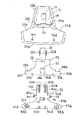
【図2】3種類の前頭部ベンチレータ構成部材および2種類の顎部ベンチレータ構成部材をそれぞれ分解した状態における図1のヘルメットの前方から見た斜視図である。
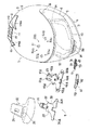
【図3】3種類の後頭部ベンチレータ構成部材をそれぞれ分解した状態における図1のヘルメットの後方から見た斜視図である。
【図4】図1のヘルメットの空気流の偏向状態を示す平面図である。
【図5】図1のヘルメットの空気流の偏向状態を示す右側面図である。
【図6】図2に示す3種類の前頭部ベンチレータ構成部材の分解背面図である。
【図7】図2に示す顎部ベンチレータ部分の背面側から見た分解斜視図である。
【図8】図1のヘルメットの頭部用および顎部用裏当て部材の分解斜視図である。
【図9】頭部用および顎部用衝撃吸収ライナに取付けられる各種の部材を省略した状態における図1のヘルメットのほゞ中央部分での縦断面図である。
【図10】図9と同様の状態における図1のヘルメットの中央部分よりもやゝ右側の部分での縦断面図である。
【図11】(a)は前頭部ベンチレータ部分の図9に示す断面部分の拡大図である。
(b)は前頭部ベンチレータ部分の図10に示す断面部分の拡大図である。
【図12】顎部ベンチレータ部分の図9および図10に示す断面部分の拡大図である。
【図13】(a)は図11(a)のA−A線における断面図である。
(b)は図12のB−B線における断面図である。
【図14】(a)はシャッタ部材が下降位置にあるときの図2に示す3種類の前頭部ベンチレータ構成部材の位置関係を示す正面図である。
(b)はシャッタ部材が中間位置にあるときの(a)と同様の図である。
(c)はシャッタ部材が上昇位置にあるときの(a)と同様の図である。
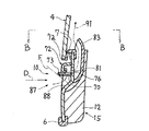
【図15】(a)はシャッタ部材が開位置にあるときの後頭部ベンチレータ部分の図10に示す断面部分の拡大図である。
(b)はシャッタ部材が閉位置にあるときの(a)と同様の図である。
【図16】(a)はシャッタ部材が開位置にあるときの図3に示す3種類の後頭部ベンチレータ構成部材の位置関係を示す正面図である。
(b)はシャッタ部材が閉位置にあるときの(a)と同様の図である。
【符号の説明】
1 フルフェイス型ヘルメット
2 帽体
4 シールド板
6 下端用縁部材
6a 突片部
22 シャッタ部材
61 額部給気用通路(第1の給気用通路)
62 額部排気用通路(第1の排気用通路)
71 シャッタ部材
87 顎部給気用通路(第2の給気用通路)
96 空気流偏向部材
97 シャッタ部材
98 排気口形成部材
99 後頭部排気用通路(第2の排気用通路)
102a 空気流偏向用曲面
104a 空気流偏向用曲面
104b 空気流偏向用曲面
121a 排気口
121b 排気口[0001]
BACKGROUND OF THE INVENTION
The present invention includes a head protector (simply referred to as a “cap body” in the text) that is mounted on a head by a motorcycle rider or the like to protect the head, and ventilates the cap body. Therefore, the present invention relates to a helmet provided with a ventilator on the cap body.
[0002]
[Prior art]
As described above, for example, a full face type helmet provided with a ventilator in the cap body to ventilate the inside of the cap body and prevent fogging of the inner surface of the shield plate is disclosed in Japanese Patent Publication No. 6-63125. Conventionally known.
[0003]
The full face type helmet described in Japanese Patent Publication No. 6-63125 (hereinafter simply referred to as “conventional helmet”) is the head of a helmet wearer such as a motorcycle rider (hereinafter simply referred to as “rider”). A frontal ventilator and a chin ventilator are respectively provided above and below a window hole provided in a full-face type cap body to be mounted on the part so as to face a face such as a rider. The frontal ventilator and the chin ventilator have a frontal air supply passage and a chin supply passage, respectively. The frontal and chin supply passages are frontal shutter members. The jaw shutter member can be opened and closed.
[0004]
Therefore, in this conventional helmet, the outside air is introduced into the inside of the cap body (that is, the internal structure of the cap body and / or the internal space for inserting the head portion of the cap body) by opening the forehead air supply passage. Can be introduced to ventilate the cap body. Also, by introducing the outside air into the cap body in the vicinity of the lower end of the inner surface of the shield plate by opening the jaw air supply passage, the introduced outside air is raised along the inner surface of the shield plate. It is possible to prevent fogging of the shield plate.
[0005]
[Problems to be solved by the invention]
However, in the conventional helmet configured as described above, the outside air introduced into the cap body through the frontal air supply passage only diffuses naturally within the cap body, so that the ventilation in the cap body is performed. Ventilation for such as cannot be performed effectively. In addition, the outside air introduced into the cap body near the lower end of the inner surface of the shield plate through the jaw air supply passage not only rises along the inner surface of the shield plate, but a considerable portion of the outside air enters the cap body. Since it diffuses naturally over a wide range, the shield plate cannot be well-fogged.
[0006]
Therefore, in the conventional helmet, when it is raining and the humidity is very high, the inside of the cap body cannot be effectively ventilated and the shield plate cannot be effectively fogged.
[0007]
The present invention makes it possible to remedy the above-mentioned drawbacks of conventional helmets very effectively with a very simple construction.
[0008]
[Means for Solving the Problems]
According to one aspect of the present invention, a cap body, Helmet wearer In a helmet comprising a shield plate attached to the cap body so as to cover a portion of the shield plate facing the face, the vicinity of the upper end of the inner surface of the shield plate is a starting end. In addition, the position above the starting end is the end. A portion of the first exhaust passage, a region facing the forehead and frontal region of the helmet wearer in the cap body, and a portion thereof in the vicinity thereof; Of the first exhaust passage. An air supply passage that terminates at a position above the starting end, a region of the cap body facing the top and back of the helmet wearer, and a part of the vicinity thereof, and the air supply passage The cap body is provided with a second exhaust passage starting from a position behind the end, and the first and second exhaust passages and the air supply passage can be opened and closed by a shutter. It is composed.
[0009]
Further, according to another aspect of the present invention, the area of the cap body facing the top and back of the helmet wearer and the vicinity thereof Part In the helmet provided with an exhaust passage starting from the cap body, an exhaust port forming member, a shutter member, and an air flow deflecting member are respectively attached to the cap body, and an exhaust port constituting a part of the exhaust passage is provided. Provided in the exhaust port forming member, configured to move the shutter member relative to the exhaust port forming member to open and close the exhaust port; A curved surface for deflecting air flow having an upwardly curved shape is provided in the air flow deflecting member, and the curved surface for air flow deflecting of the air flow deflecting member obliquely upwards the air flow near the end of the exhaust passage. To be away from this end Positioning and holding the exhaust port forming member by the air flow deflecting member Configure to It is a thing.
[0010]
DETAILED DESCRIPTION OF THE INVENTION
Next, an embodiment in which the present invention is applied to a full-face helmet will be described with reference to FIGS.
[0011]
As shown in FIG. 1, the full-face helmet 1 includes a full-face cap body 2 attached to the head of a motorcycle such as a rider, and a forehead and a jaw (such as a face). ), A shield plate 4 that can open and close the window hole 3 formed on the front surface of the cap body 2 and a pair of left and right chin straps (cap body 2 in FIG. (It is not shown in the figure because it is contained in the interior of the main body, but it may be a well-known one). And the area | region facing each forehead part and frontal heads, such as a rider in the cap body 2, and its vicinity Part Is provided with a forehead ventilator 9, in the region facing the jaw and the vicinity thereof Part Is provided with a chin ventilator 10, which is a region facing the rear part of the top of the head and the upper part of the occipital region, and the vicinity thereof. Part Is provided with a occipital ventilator 8. The cap body 2 may have a conventionally well-known configuration except for the portions related to the forehead, jaw, and occipital ventilators 9, 10, and 8.
[0012]
Therefore, as shown in FIGS. 1, 3, 5, 7, 7, 8, 11 and 15, etc., the cap body 2 has a full face-shaped outer side that constitutes the outer peripheral wall of the cap body 2. A cross-section attached by bonding or the like over the entire circumference of the shell 5, a substantially U-shaped lower edge member 6 attached to the entire periphery of the lower end of the outer shell 5, and the window hole 13 of the outer shell 5. A substantially E-shaped window hole edge member 7 is bonded to the inner peripheral surface of the outer shell 5 in a region facing the frontal head, the top, the left and right heads, and the back of the head, such as a rider. The head backing member 14 attached by the above and the jaw / cheek backing member attached by contact with the inner peripheral surface of the outer shell 5 in the region facing the jaw and cheeks, such as a rider, by bonding or the like It can consist of fifteen. The outer shell 5 may be made of a composite material in which a flexible sheet such as a nonwoven fabric is lined on the inner peripheral surface of the shell body having a high strength made of FRP, other hard synthetic resin, and the like. The member 6 may be made of foamed vinyl chloride, synthetic rubber, or other soft synthetic resin, and the window hole edge member 7 may be made of synthetic rubber or other flexible elastic material. .
[0013]
As clearly shown in FIGS. 3 and 5, a crescent-shaped projecting piece 6 a protruding outward is integrally formed on the rear portion of the lower end edge member 6, and a rider or the like is formed along the outer peripheral surface of the outer shell 5. The air flow which is going to descend toward the neck of the head is shielded by the projecting piece 6a. Further, the lower edge of the window hole edge member 7 is clearly shown in FIG. Do As described above, when the projecting piece portion 7a projecting outward substantially over the entire length is integrally formed and the shield plate 4 is closed, the lower end of the shield plate 4 comes into contact with the projecting piece portion 7a. It may be.
[0014]
As shown in FIG. 8, the head backing member 14 has a shock absorbing liner 11 for the head and an inner peripheral surface of the shock absorbing liner 11 in a region excluding a region facing the left and right side heads such as a rider. It may consist of a breathable head backing cover 17 attached by adhesive, tape fastening or the like so as to cover it. In FIG. 8, only the head backing cover 17 is shown in a rear view. As shown in FIG. 8, the chin / cheek backing member 15 is configured to absorb the chin / cheek shock absorbing liner 12 and the chin / cheek shock absorbing region 12 in a region facing the left and right cheeks such as a rider. It may consist of a pair of left and right block-like interior pads 18a, 18b attached to the inner peripheral surface of the liner 12 by adhesion or the like.
[0015]
The body parts of the shock absorbing liner 11 for the head and the shock absorbing liner 12 for the chin and cheeks may each be made of a material having appropriate rigidity and appropriate plasticity, such as expanded polystyrene and other synthetic resins. The body portion of the head backing cover 17 is laminated with a layer made of a flexible elastic material such as urethane foam or other synthetic resin on the surface facing the head impact absorbing liner 11. The body part of the pair of block-shaped interior pads 18a and 18b may be made of an elastic material rich in flexibility such as urethane foam or other synthetic resin.
[0016]
As is conventionally known, the shield plate 4 is rotatably attached to the cap body 2 by a pair of left and right mounting screws 16. The shield plate 4 closes the window hole 3 at the backward rotation position, and opens the window hole 3 at the forward rotation position rotated upward from the backward rotation position. In this position, the window hole 3 can be partially opened. The shield plate 4 may be made of a transparent or translucent hard material such as polycarbonate or other synthetic resin.
[0017]
As clearly shown in FIGS. 2 and 6, the forehead ventilator 9 includes three types of forehead ventilator constituting members including a cover member 21, a shutter member 22, and an air supply / exhaust port forming member 23. These three types of ventilator constituent members may be made of materials having appropriate elasticity and appropriate rigidity, such as polycarbonate, polyacetal, ABS, nylon, and other synthetic resins. For example, the material of these three types of frontal ventilator constituent members may be polycarbonate, respectively, and the material of these three types of frontal ventilator constituent members may be made different from each other so that the cover member 21 is polycarbonate and the shutter. The member 22 and the air supply / exhaust port forming member 23 may be polyacetal, ABS, or nylon.
[0018]
As shown in FIGS. 2 and 6, a plurality of, for example, four mounting pins 24a, 24b, 24c, and 24d are integrally formed on the back surface of the cover member 21, respectively. An air intake 25 having a slit shape is formed, and a knob insertion opening 26 is formed at the upper portion thereof. Further, a shielding wall portion 29 is integrally formed on the back surface of the cover member 21 along the upper end edge of the air intake port 25, and the outer periphery of the back surface (as a result, a pair of left and right cut portions 27 a and 27 b is formed. Except for the above, a pair of upper and lower joint surfaces 28a, 28b are provided to project. The shielding wall portion 29 has a function of preventing the outside air taken in from the air intake port 25 from moving upward.
[0019]
As shown in FIGS. 2 and 6, an operation knob portion 31 is integrally formed on the front surface of the shutter member 22 so as to correspond to the knob insertion opening 26 of the cover member 21. The click projections 32a and 32b having elasticity are integrally formed. In addition, an air supply port 33 that is, for example, a substantially oblong elliptical shape is formed in the center of the shutter member 22 so as to correspond to the air intake port 25 of the cover member 21. In the center of the lower portion of the shutter member 22, for example, a rectangular cut 35 is provided in order to form a pair of left and right sliding portions 34a and 34b. The shutter member 22 is integrally formed with a pair of shielding arm portions 36a and 36b so as to be positioned on both the left and right sides of the cut 35, and a cover is provided below the pair of shielding arm portions 36a and 36b. Corresponding to the pair of left and right mounting pin portions 24c, 24d provided at the lower end portion of the member 21, for example, approximately half-circular relief recesses 37a, 37b are formed. A pair of left and right exhaust notches 38a and 38b are formed at the upper ends of the pair of shielding arm portions 36a and 36b, respectively.
[0020]
As shown in FIGS. 2 and 6, a pair of left and right cross sections for guiding the click protrusions 32 a and 32 b of the shutter member 22 are substantially L-shaped, for example, at the upper portion of the air supply / exhaust port forming member 23. The channel-shaped guide portions 41a and 41b are integrally formed so as to extend in the vertical direction. The supply / exhaust port forming member 23 is provided with a pair of left and right click recesses 42a, 42b, 42c, for example, along the guide portions 41a, 41b. In addition, an air supply port 43 that is substantially the same shape as the air supply port 33 is provided at the center of the air supply / exhaust port forming member 23 so as to correspond to the air supply port 33 of the shutter member 22. In the outer periphery of 43, a tubular projecting wall portion 49 projecting to the back side of the air supply / exhaust port forming member 23 is integrally formed. A pair of left and right engagement arm portions 45 a and 45 b each having an engagement hole 44 are provided in the central portion of the cover member 21 near the left and right sides of the air supply port 43 in the air supply / exhaust port forming member 23. A pair of left and right mounting pin portions 24a and 24b are integrally formed correspondingly.
[0021]
As shown in FIGS. 2 and 6, a pair of left and right sides having a L-shaped cross section, for example, corresponding to the pair of left and right sliding portions 34 a and 34 b of the shutter member 22, are provided below the air supply / exhaust port forming member 23. The channel-shaped guide portions 46a and 46b are integrally formed so as to extend substantially in the vertical direction, and the air supply / exhaust port forming member 23 has a pair of left and right guides so as to be located on both the left and right sides of the pair of guide portions 46a and 46b, respectively. The arm portions 47a and 47b are integrally formed. The pair of arm portions 47a and 47b are respectively formed with a pair of left and right exhaust ports 48a and 48b corresponding to the pair of left and right exhaust notches 38a and 38b of the shutter member 22, respectively. On the outer periphery of the exhaust ports 48a and 48b, the pair of left and right projecting wall portions 50a and 50b projecting to the back side of the air supply and exhaust port forming member 23 are integrally formed.
[0022]
As clearly shown in FIGS. 2 and 7, the jaw ventilator 10 includes two types of jaw ventilator constituting members including a shutter member 71 and a cover member 72 serving also as an air supply port forming member. These two types of jaw ventilator constituent members have appropriate elasticity and appropriate rigidity, such as polycarbonate, polyacetal, ABS, nylon, and other synthetic resins, in the same manner as the frontal ventilator constituent members. It may be made of material. Therefore, the material of the shutter member 71 and the cover member 72 may be polycarbonate, Also, The shutter member 71 may be polyacetal, ABS, or nylon, and the cover member 72 may be polycarbonate.
[0023]
As shown in FIGS. 2 and 7, the shutter member 71 includes a base portion 65 configured in, for example, a horizontally long vertical plate shape, and a large number of integrally projecting inward from the inner side surface of the base portion 65. And the operation knob 73 integrally formed on the outer surface of the base body 65. A large number of air supply cuts 76 are formed between the large number of comb teeth 66. A pair of left and right click recesses 74 a and 74 b is formed on the inner surface of the base portion 65.
[0024]
As shown in FIGS. 2 and 7, the cover member 72 includes, for example, a base portion 67 configured in a generally horizontally long cup shape, and a pair of left and right screws projecting integrally on the inner surface of the base portion 67. Cylindrical shaft portions 68a and 68b, and a sliding guide portion 69 for guiding the shutter member 71 to slide in the left-right direction. A large number of air supply cuts 70 functioning as air supply openings are formed on the lower surface of the base portion 67 so as to correspond to the large number of comb teeth portions 66 of the shutter member 71, respectively. A number of comb teeth 75 are formed between the cuts 70. Further, a knob insertion opening 85 is provided at the center lower portion of the outer surface of the base body 67 so as to correspond to the operation knob 73 of the shutter member 71. Further, a click protrusion (not shown) that selectively engages with the click recesses 74 a and 74 b of the shutter member 71 is integrally formed on the outer surface of the sliding guide portion 69.
[0025]
As clearly shown in FIGS. 3 and 16, the occipital ventilator 8 includes three types of occipital ventilator constituting members including an air flow deflecting member 96 also serving as an attachment member, a shutter member 97, and an exhaust port forming member 98. These three types of ventilator components, like the forehead ventilator component and the jaw ventilator component, have appropriate elasticity and appropriate rigidity such as polycarbonate, polyacetal, ABS, nylon, and other synthetic resins. And may each be made of a material having For example, the material of these three types of occipital ventilator constituent members may be polycarbonate, and the material of these three types of occipital ventilator constituent members may be made different from each other so that the air flow deflecting member 96 is polycarbonate and the shutter member 97. The exhaust port forming member 98 may be made of polyacetal, ABS, or nylon.
[0026]
The air flow deflecting member 96 for stabilizing the air flow in the vicinity of the upper portion of the rear wall portion of the cap body 2 includes a pair of left and right wings having a generally triangular shape as shown in FIGS. Parts 101a and 101b, and an elongated connecting part 102 that integrally connects the pair of wing parts 101a and 101b at their rear end parts. The central portion of the air flow deflecting member 96 is provided with a generally rectangular cut 103 that is adjacent to the connecting portion 102 and opens on the opposite side (that is, the front end side) of the connecting portion 102. Yes. Further, the projecting piece 106 is integrally formed along the substantially entire length of the rear end of the inner side surface of the connecting portion 102. For this reason, the rear end portion 102a of the connecting portion 102 has a shape bent upward. Thus, a curved surface 102a for air flow deflection is configured. Further, the pair of left and right adjacent portions adjacent to the connecting portion 102 at the rear end portions of the pair of wing portions 101a and 101b have shapes that are bent obliquely upward and obliquely, respectively, and are curved surfaces for air flow deflection. 104a and 104b are configured. Further, a plurality of relatively large diameters, for example, a pair of mounting pin portions 105 a and 105 b are integrally formed on the inner surface of the air flow deflecting member 96. In the vicinity of the notch 103 on the inner surface of the air flow deflecting member 96, a plurality of, for example, three mounting pin portions 107a, 107b, 107c having a relatively small diameter are integrally formed.
[0027]
As shown in FIGS. 3, 15 and 16, the shutter member 97 is configured, for example, in a generally rectangular plate shape, and is a protrusion that is integrally formed and extended along the substantially entire length of the rear end of the outer surface thereof. Is curved outward and constitutes a curved surface 111 for deflecting airflow. This protrusion 111 serves as both the handle of the shutter member 97 and the air flow deflecting means. In addition, a plurality of, for example, three guide projections 112a, 112b, and 112c are integrally formed on the inner surface of the shutter member 97, and the cross section is substantially inverted at the rear end of the central guide projection 112b. A letter-shaped retaining portion 113 is integrally formed. Further, a pair of left and right click protrusions 114 a and 114 b are integrally formed on the inner surface of the shutter member 97.
[0028]
As shown in FIGS. 3, 15, and 16, the exhaust port forming member 98 is provided with a pair of left and right exhaust ports 121a, 121b that are, for example, substantially oblong ellipses, and the exhaust ports 121a, 121b In the outer periphery, a tubular projecting wall portion 122 projecting inward is integrally formed on the inner side surface of the exhaust port forming member 98. The exhaust port forming member 98 is provided with three guide slits 123a, 123b, 123c corresponding to the guide projections 112a, 112b, 112c of the shutter member 97, respectively. An insertion opening 124 is connected to the rear end corresponding to the retaining portion 113 of the shutter member 97. Further, the exhaust port forming member 98 is provided with engagement holes 125a, 125b, and 125c corresponding to the mounting pin portions 107a to 107c of the air flow deflecting member 96, respectively. Further, on the outer surface of the exhaust port forming member 98, a pair of left and right click recesses 115a, 115b, 116a, and 116b corresponding to the click protrusions 114a and 114b of the shutter member 97 are provided on the left and right sides. It has been.
[0029]
As shown clearly in FIG. 2, a portion of the outer shell 5 such as a rider facing the forehead and the forehead and a part of the vicinity thereof includes an air supply port 43 of the air supply / exhaust port forming member 23 and a pair of left and right parts. An air supply port 51 and a pair of left and right exhaust ports 52a and 52b are formed so as to correspond to the exhaust ports 48a and 48b, respectively, and mounting holes 53a corresponding to the mounting pin portions 24a to 24d of the cover member 21, respectively. , 53b, 53c, 53d are formed. Further, as shown in FIGS. 2 and 7, a part of the outer shell 5 facing the jaw portion such as a rider and a part of the vicinity thereof is substantially horizontally long, for example, correspondingly to the cover member 72. A slit-shaped air supply port 81 is formed, and a recess 86 is formed in the outer shell 5 so as to surround the air supply port 81. Further, as shown clearly in FIG. 3, a pair of left and right exhaust port forming members 98 are provided in a part of the outer shell 5 such as a rider that faces the rear part of the top of the head and the upper part of the back of the head. A pair of left and right exhaust ports 131a and 131b are formed corresponding to the exhaust ports 121a and 121b, and a pair of left and right mounting holes corresponding to the pair of left and right mounting pin portions 105a and 105b of the air flow deflecting member 96. 132a and 132b are formed.
[0030]
As shown clearly in FIG. 8, an air supply port of the outer shell 5 is formed in a part of the region facing the forehead and the frontal region of the main body portion of the shock absorbing liner 11 for the head and the frontal head. An air supply port 54 is formed so as to substantially correspond to 51, and exhaust vertical grooves 55a, 55b are formed so as to open to the outer peripheral surface thereof so as to correspond to the intake ports 52a, 52b, respectively. Further, these exhaust vertical grooves 55a and 55b communicate with the side surfaces of the main body portion of the shock absorbing liner 11 for the head (that is, the narrow surface existing between the outer peripheral surface and the inner peripheral surface). A lateral groove 56 is formed. Further, exhaust portions 131a and 131b of the outer shell 5 are provided in a part of the region facing the rear portion of the top of the head and the upper portion of the back of the head in the main body portion of the shock absorbing liner 11 for the head and a part of the vicinity thereof. A pair of left and right exhaust ports 57a and 57b are formed correspondingly to each other. Further, a pair of left and right exhaust recesses 153a and 135b are formed in the rear end central portion of the head impact absorbing liner, and these recesses 135a and 135b are formed from the inner peripheral surface of the liner 11 to the rear side surface ( It extends to the outer peripheral end of a narrow surface existing between the inner peripheral surface and the outer peripheral surface.
[0031]
As shown in FIGS. 7 and 8, in the central upper part of the body portion of the impact absorbing liner 12 for the jaw, a horizontally long air supply recess 82 opened upward is formed in the recess 86 of the outer shell 5. In the air supply recess 82, for example, a horizontally long and dish-shaped air guide plate 83 is attached to the liner 12 so as to face forward. A pair of attachment holes 84a and 84b for attaching the base end portions of a pair of left and right chin straps (not shown) are provided on the left and right sides of the impact absorbing liner 12 for the chin portion.
[0032]
As clearly shown in FIG. 8, locking members 141 and 142 are respectively attached to the front end portion and the rear end portion of the head backing cover 17, and the front end portion and the rear end portion of the head shock absorbing liner 11 are attached. The locking members 143 and 144 are attached to the locking members 141 and 142 so as to correspond to the locking members 141 and 142, respectively. Then, a pair of locking pins 145a, 145b, 146a, 146b provided on the locking members 141, 142 on the head backing cover 17 side are provided on the locking members 143, 144 on the head shock absorbing liner 11 side. By fitting and fixing to the pair of locking holes 147a, 147b, 148a, 148b, respectively, 17 Is attached to the liner 11.
[0033]
As shown clearly in FIG. 8, the air supply of the shock absorbing liner 11 for the head is provided in a part of the region facing the forehead and the frontal region of the head backing cover 17 such as the forehead and the frontal head. An air supply port 149 is provided substantially corresponding to the port 54, and a plurality of, for example, four openings 150 are provided around the air supply port 149. Further, as clearly shown in FIG. 8, there is a head impact in the region facing the rear portion of the top of the head and the upper portion of the back of the head, such as a rider, in the head backing cover 17. A pair of left and right exhaust ports 151a and 151b are provided corresponding to the exhaust ports 57a and 57b of the absorption liner 11, respectively. Further, the locking member 141 is provided with three exhaust ports 152a, 152b, 152c corresponding to the lower ends of the exhaust vertical grooves 55a, 55b of the head impact absorbing liner 11, respectively. In addition, three exhaust ports 161a, 161b, 161c are provided so as to substantially correspond to these exhaust ports 152a, 152b, 152c. The locking member 144 is also provided with a pair of left and right exhaust ports 162a and 162b corresponding to the exhaust recesses 135a and 135b of the liner 11.
[0034]
Of the holding member 144, the side end surface of the head impact absorbing liner 11 (that is, a narrow surface existing between the inner peripheral surface and the outer peripheral surface of the liner 11) is a net to improve air permeability. Configured. Further, on the lower surface of the crescent-shaped projecting piece portion 6a of the lower edge member 6, exhaust groove portions 163a and 163b are formed so as to substantially correspond to the exhaust groove portions 135a and 135b of the liner 11, respectively. . Accordingly, the air inside the cap body 2 is also shielded by the crescent-shaped projecting piece portion 6a from the air flow that is going to descend along the outer peripheral surface of the outer shell 5, so that the exhaust recess portions 135a, 135b And the exhaust recesses 163a and 163b, respectively, are effectively discharged to the outside.
[0035]
As clearly shown in FIG. 8, locking members 153 are attached to the outer surfaces of the block-shaped interior pads 18 a and 18 b, respectively, and the locking members 153 are mounted on the inner surface of the chin / cheek shock absorbing liner 12. A locking member 154 is attached correspondingly. Then, by fitting and fixing a pair of locking pins 155 provided on the locking members 153 on the interior pads 18a and 18b side to a pair of locking holes 156 respectively provided on the locking members 154 on the liner 12 side, The interior pads 18a and 18b are attached to the liner 12, respectively. Furthermore, a supported member 157 is attached to the lower end portions of the interior pads 18a and 18b, and a pair of left and right holding members 158 having a folded structure are attached to the lower end portion of the liner 12, respectively. And Holding member 157 is sandwiched and supported by a holding member 158 having the folded structure.
[0036]
The step of attaching the three types of frontal ventilator components (that is, the cover member 21, the shutter member 22, and the air supply / exhaust port forming member 23) to the cap body 2 to obtain the state shown in FIG. The order described in items (3) to (3) may be used.
(1) A narrow and generally rectangular upper portion of the shutter member 22 (that is, a generally rectangular portion in which the operation knob portion 31 and the click projections 32a and 32b are respectively formed) is an air supply / exhaust port forming member. 23 are inserted into the channel-shaped guide portions 41a and 41b from the lower ends of the guide portions 41a and 41b, and slide upward until the click projection portions 32a and 32b are respectively fitted to the pair of left and right upper click recesses 42a. Let Next, after the shutter member 22 is slightly tilted in the left-right direction, one of the left and right sliding portions 34a, 34b of the shutter member 22 is used as a pair of channel-shaped guide portions 46a of the air supply / exhaust port forming member 23. 46b, one of the guide portions corresponding to this is fitted, and then the shutter member 22 is slightly elastically deformed to fit the other sliding portion to the other guide portion. As a result, the shutter member 22 can slide in the vertical direction on the air supply / exhaust port forming member 23.
Can be installed in
(2) Next, the mounting pin portions 24a and 24b of the cover member 21 are fitted into the pair of left and right engaging holes 44 formed in the pair of left and right engaging arm portions 45a and 45b of the air supply / exhaust port forming member 23, respectively. Combine. As a result, the air supply / exhaust port forming member 23 and thus the shutter member 22 can be attached to the cover member 21. In this case, the operation knob 31 of the shutter member 22 faces the outer surface of the cover member 21 from the knob insertion opening 26 of the cover member 21. Further, when the shutter member 22 is lowered and the pair of click protrusions 32a and 32b are fitted into the pair of left and right lower click recesses 42c, the pair of left and right mounting pin portions 24c and 24d of the cover member 21 are moved to this position. A pair of left and right relief recesses of the shutter member 22
It enters into 37a and 37b, respectively.
(3) Next, after applying an adhesive or attaching a double-sided adhesive tape to the pair of upper and lower joining surfaces 28a, 28b of the cover member 21, the mounting pin portions 24a-24d of the cover member 21 are attached to the mounting holes of the outer shell 5. 53a to 53d are respectively fitted, and the projecting wall portions 49, 50a, 50b of the air supply / exhaust port forming member 23 are fitted to the air supply port 51 and the exhaust ports 52a, 52b of the outer shell 5, respectively. , 28b are brought into close contact with a region facing the forehead portion such as a rider on the outer peripheral surface of the outer shell 5. In this case, as shown in FIG. 8, the front end portions of the projecting wall portions 49, 50a, 50b of the air supply / exhaust port forming member 23 are connected to the air supply port 54 and the exhaust vertical grooves 55a, 55b of the head impact absorbing liner 11. Are also inserted respectively. As a result, the cover member 21 and thus the shutter member 22 and the air supply / exhaust port forming member 23 can be attached to the outer shell 5. Therefore, the cover member 21 also serves as an attachment member or a positioning member for attaching the air supply / exhaust port forming member 23 to the cap body 2. In this case, the cover member is locked by locking a locking ring (not shown) at the tip of the mounting pin portions 24a to 24d of the cover member 21 fitted in the mounting holes 53a to 53d of the outer shell 5, respectively. 21 can be firmly bonded to the outer shell 5, and for this purpose, the bonding of both with an adhesive or a double-sided adhesive tape can be omitted if necessary. Further, the inner surface of the air supply / exhaust port forming member 23 is attached to the outer shell 5 as required by an adhesive or a double-sided adhesive tape.
It may be adhered directly by a screw.
[0037]
In the frontal ventilator 9 configured as described above, as clearly shown in FIG. 11A, the outside (outside air) → the air intake port 25 of the cover member 21 → the air supply port 33 of the shutter member 22 → the supply air Air supply port 43 and protrusion 49 of the exhaust port forming member 23 → Air supply port 51 of the outer shell 5 → Air supply port 54 of the head shock absorbing liner 11 → Air supply port 149 of the head backing cover 17 An air supply passage (hereinafter referred to as “frontal air supply passage”) 61 is formed. Then, as shown in FIG. 11A, the frontal intake passage 61 communicates with the outside (outside air) at its start end (that is, the outer end of the air intake port 25 of the cover member 21), and its terminal end. In the vicinity of (that is, the inner end of the air supply port 149 of the cover 17), the cap body 2 communicates with the inside. The outside air introduced to the end through the forehead intake passage 61 moves from the front to the rear in the cap body 2.
[0038]
The outer end of the air intake port 25, which is the starting end of the front head air supply passage 61, is the relative movement direction of the outside air as generally seen, as indicated by a two-dot chain line C in FIG. Since this is open toward the arrow D direction side and is not open toward the opposite direction side (that is, it opens toward the front side instead of the rear side), this passage 61 is configured for air supply. Has been. The two-dot chain line C is a straight line connecting the upper end and the lower end of the air intake port 25. The forehead air supply passage 61 is closed by closing the air supply port 43 of the air supply / exhaust port forming member 23 with the pair of left and right shielding arm portions 36a, 36b of the shutter member 22. it can.
[0039]
In the forehead ventilator 9, as clearly shown in FIG. 11B, the exhaust ports 152a, 152b, 152c of the head backing cover 17 → the exhaust ports 161a, 161b, 161c of the locking member 143 → the head. The horizontal groove 56 of the shock absorbing liner 11 and the vertical grooves 55a and 55b for exhaust → the projecting wall portions 50a and 50b of the air supply / exhaust port forming member 23 and the exhaust ports 48a and 48b → the exhaust notches 38a and 38b of the shutter member 22 → the cover. A gap 58 between the inner side surface of the member 21 and the outer side surface of the air supply / exhaust port forming member 23 or the outer peripheral surface of the outer shell 5 → a discontinuous portion of the cover member 21 Exhaust passages (hereinafter referred to as “external air”) that are formed between the air outlets 59 a and 27 b and the outer peripheral surface of the outer shell 5. "Forehead exhaust passage" hereinafter) 62 is also formed. The air intake port 59 is sufficiently separated from the air intake port 25 of the forehead air supply passage 61. The discharge ports 152a, 152b, 152c are located sufficiently below the air supply port 149. Then, as shown in FIG. 11 (b), the front head exhaust passage 62 has a shield plate 4 at its starting end (that is, the lower end of the exhaust ports 152 a and 152 b of the head backing cover 17). It communicates with the vicinity of the upper part of the inner peripheral surface, and communicates with the outside (outside air) at its end (that is, the outer end of the air outlet 59).
[0040]
As shown by a two-dot chain line E in FIG. 11 (b), the outer end of the air outlet 59, which is the end of the front head exhaust passage 62, is an arrow indicating the relative movement direction of outside air as generally seen. Since it is not open toward the D direction side and is open toward the opposite direction side (that is, it opens toward the rear side instead of the front side), the passage 62 is for exhaust. It is configured as. The two-dot chain line E is a perpendicular line that extends from the tips of the interrupted portions 27 a and 27 b of the cover member 21 to the outer peripheral surface of the outer shell 5. The forehead exhaust passage 62 can be opened by closing the exhaust ports 48 a and 48 b of the air supply / exhaust port forming member 23 with the central portion of the shutter member 22. Note that the inclination angle of the outer end of the air outlet 59 (that is, the inclination of the two-dot chain line E with respect to the direction of the arrow D) is about 15 ° in the case of illustration, but generally from the viewpoint of practicality. The angle is preferably 5 ° to 40 °, and more preferably 10 ° to 30 °.
[0041]
In the frontal ventilator 9 configured as described above, when the operation knob 31 is pinched with a finger and the shutter member 22 is slid up and down to selectively move to the lowered position, the intermediate position, and the raised position, Since the click protrusions 32a and 32b of the shutter member 22 selectively engage with the upper, middle and lower click recesses 42a, 42b and 42c of the air supply / exhaust port forming member 23, as shown in FIG. The shutter member 22 can be held at three positions. That is, in the first position where the click protrusions 32a and 32b are engaged with the pair of left and right lower click recesses 42c (that is, in the state of FIGS. 11 and 14A), the shutter member 22 is Since both the air supply port 43 and the exhaust ports 48a and 48b of the air supply / exhaust port forming member 23 are opened, the front head air supply passage 61 and the front head exhaust passage 62 are both open. Yes. Also, click protrusions 32a and 32b Left and right pair The shutter member 22 closes the air supply port 43 of the air supply / exhaust port forming member 23 in the second position (that is, the state shown in FIG. 14B) engaged with the intermediate click recess 42b. However, since the exhaust ports 48a and 48b are open, the frontal air supply passage 61 is closed, but the frontal exhaust passage 62 is open. Further, in the third position (that is, the state shown in FIG. 14C) in which the click protrusions 32a and 32b are engaged with the pair of left and right upper click recesses 42c, the shutter member 22 forms the air supply / exhaust port. Since both the air supply port 43 and the exhaust ports 48a and 48b of the member 23 are closed, the front head supply passage 61 and the front head exhaust passage 62 are both closed.
[0042]
The steps of attaching the two types of jaw ventilator constituent members (that is, the shutter member 71 and the cover member 72 serving as the air supply port forming member) to the cap body 2 to obtain the state shown in FIG. It may be the order of item (2).
(1) After the comb tooth portion 75 of the cover member 72 is heard outward, the shutter member 71 is moved along the inner surface of the lower wall portion of the cover member 72 (that is, the comb tooth portion 75). 72, the base portion 65 of the shutter member 71 is slidably inserted into the sliding guide portion 69 of the cover member 72, and the operation knob portion 73 of the shutter member 71 is inserted into the cover member 72. It is inserted into the knob insertion opening 85 and protrudes outward and forward.
(2) Next, a pair of screws 164 a and 164 b respectively inserted into the air guide plate 83 and the screw insertion holes of the outer shell 5 are screwed into the pair of screw holes 68 a and 68 b of the cover member 72. The cover member 72 and thus the shutter member 71 are attached to the outer shell 5 by bringing the outer periphery into close contact with the outer surface of the recessed portion 86 of the outer shell 5.
[0043]
In the jaw ventilator 10 configured as described above, as clearly shown in FIG. 12, between the outside (outside air) → the inclined outer surface of the recessed portion 86 of the outer shell 5 and the lower wall portion of the cover member 72. For example, a substantially oblong recess 88 → an air supply cut 70 of the cover member 72 → an air supply cut 76 of the shutter member 71 → an internal space of the cover member 72 → an air supply port 81 of the outer shell 5 → an inside of the air guide plate 83 An air supply passage (hereinafter referred to as “jaw portion air supply passage”) 87 formed of a space is formed. Then, as shown in FIG. 12, the jaw portion air supply passage 87 has a starting end (that is, a portion between the inclined outer surface of the recessed portion 86 of the outer shell 5 and the lower wall portion of the cover member 72). It communicates with the outside (outside air) at the outer end of the horizontally long recess 88 and communicates with the vicinity of the lower part of the inner surface of the shield plate 4 at its end (ie, near the upper end of the internal space of the air guide plate 83). .
[0044]
As shown by a two-dot chain line F in FIG. 12, the outer end of the recess 88, which is the starting end of the jaw air supply passage 87, generally faces the arrow D direction side, which is the relative movement direction of the outside air. The passage 87 is configured to supply air, since the opening 87 is not open toward the opposite direction side (that is, the opening is directed toward the front side rather than the rear side). The two-dot chain line F is a perpendicular line that extends from the front end of the lower wall portion of the cover member 72 to the outer peripheral surface of the outer shell 5 (specifically, the outer surface of the recessed portion 86). The jaw air supply passage 87 can be opened by closing the air supply port 70 of the air supply port forming member 72 with the comb-tooth portion 66 of the shutter member 71.
[0045]
In the jaw ventilator 10 configured as described above, the operation member 73 is pinched with a finger and the shutter member 71 is slid to the left and right, whereby the click recesses 74a and 74b of the shutter member 71 are inserted into the click recesses 74a and 74b. By selectively engaging a click protrusion (not shown), the shutter member 71 can be held in two positions. That is, in the first position where the click protrusion is engaged with one click recess 74b (that is, the state shown in FIG. 12), the air supply notch 76 of the shutter member 71 is also used as the air supply port forming member. The air supply notch 70 is opened in agreement with the air supply cut 70 of the cover member 72, so that the jaw air supply passage 87 is open. In the second position where the click protrusion is engaged with the other click recess 74a, the comb teeth 66 of the shutter member 71 closes the air supply cut 70 of the cover member 72. The partial air supply passage 87 is closed.
[0046]
The steps of attaching the three types of occipital ventilator constituent members (that is, the air flow deflecting member 96, the shutter member 97, and the exhaust port forming member 98) to the cap body 2 to the state shown in FIG. The order described in the item (c) may be used.
(A) After the retaining portion 113 of the shutter member 97 is inserted into the insertion opening 124 of the exhaust port forming member 98 from the outer surface of the member 98, the shutter member 97 is advanced relative to the exhaust port forming member 98. The three guide protrusions 112a, 112b, and 112c of the shutter member 97 are fitted into the three guide slits 123a, 123b, and 123c of the exhaust port forming member 98, respectively. Thus, the shutter member 97 can be attached to the exhaust port forming member 98 so as to be slidable in the front-rear direction.
(B) Next, the three attachment pin portions 107a, 107b, and 107c of the air flow deflecting member 98 are fitted into the three engagement holes 125a, 125b, and 125c formed in the exhaust port forming member 98, respectively. As a result, the exhaust port forming member 98 and thus the shutter member 97 can be attached to the air flow deflecting member 96. In this case, the exhaust port forming member 98 has a thin mounting portion 98a formed in a substantially U shape around the outer periphery thereof (three engagement holes 125a, 125b, 125c are provided in the mounting portion 98a). When the shutter member 97 is in its closed position, as shown in FIG. 16 (a), the top of the notch 103 is Is located.
(C) Next, after applying an adhesive or adhering a double-sided adhesive tape to the inner side surfaces of the pair of wing portions 101a and 101b and the lower end surface of the projecting piece 106 of the air flow deflecting member 96, the exhaust port forming member 98 is applied. The outer peripheral protruding wall portions 122 of the pair of exhaust ports 121a and 121b are fitted into the exhaust ports 131a and 131b of the outer shell 5, respectively, and the pair of mounting pin portions 105a and 105b of the air flow deflecting member 96 are connected to the outer shell. 5 are respectively fitted to a pair of mounting holes 132a and 132b so that the inner surface of the air flow deflecting member 96 faces the rear part of the top of the head and the upper part of the back of the outer shell 5 on the outer peripheral surface of the outer shell 5, respectively. And in the vicinity Part Adhere to and adhere. Thus, the air flow deflecting member 96, and thus the shutter member 97 and the exhaust port forming member 98 can be attached to the outer shell 5. Therefore, the air flow deflecting member 96 also serves as an attachment member or a positioning member for attaching the exhaust port forming member 98 to the cap body 2. In this case, a locking ring (not shown) is locked to the tip of the mounting pin portions 105a and 105b of the air flow deflecting member 96 fitted in the mounting holes 132a and 132b of the outer shell 5, respectively. The air flow deflecting member 96 can be firmly bonded to the outer shell 5, and for this purpose, the bonding of both with an adhesive or a double-sided adhesive tape can be omitted if necessary. Moreover, you may adhere | attach the inner surface of the exhaust port formation member 98 on the outer shell 5 directly with an adhesive agent or a double-sided adhesive tape as needed.
[0047]
In the occipital ventilator 8 configured as described above, as clearly shown in FIG. 15 (a), the exhaust ports 151a and 151b of the head backing cover 17 → the exhaust ports 57a of the shock absorbing liner 11 for the head. 57b → exhaust port 131a, 131b of outer shell 5 → projecting wall 122 of exhaust port forming member 98 → exhaust port 121a, 121b of exhaust port forming member 98 → tip of protrusion 111 of shutter member 97 and exhaust port forming member An exhaust passage 99 (hereinafter referred to as “rear head exhaust passage”) 99 formed by a gap formed between 98 exhaust ports 121a and 121b and the outside (outside air) is formed. Then, as shown in FIG. 15 (a), the rear head exhaust passage 99 is located inside the cap body 2 at its starting end (that is, the lower end of the exhaust ports 151a and 151b of the head backing cover 17). A region such as a rider that communicates with a rear portion of the top of the head and an upper portion of the back of the head and a portion in the vicinity thereof, and ends thereof (that is, the tip of the protrusion 111 of the shutter member 97 and the exhaust of the exhaust port forming member 98). A gap formed between the rear ends of the ports 121a and 121b) communicates with the outside (outside air).
[0048]
As shown by a two-dot chain line G in FIG. 15 (a), the end of the rear head exhaust passage 99 is open toward the direction of the arrow D, which is the relative movement direction of outside air as generally seen. The passage 99 is configured to be used for exhaust gas because it is open toward the opposite side (that is, opened toward the rear rather than the front). The two-dot chain line G is a perpendicular line extending from the front end of the protrusion 111 of the shutter member 97 to the rear ends of the exhaust ports 121a and 121b of the exhaust port forming member 98. The occipital exhaust passage 99 can be opened by closing the exhaust ports 121a and 121b of the exhaust port forming member 98 with the shutter member 97, as shown in FIG.
[0049]
As shown in FIGS. 4, 5, and 15, means for stabilizing the air flow are arranged at the end of the rear head exhaust passage 99 and around the exhaust ports 121a and 121b of the exhaust port forming member 98. Yes. That is, the air flow deflecting curved surface 111 formed by the protrusions of the shutter member 97 deflects the air flow that tends to flow from the front to the rear toward the space above the exhaust ports 121a and 121b. An air flow deflecting curved surface 102a formed from the rear end portion of the connecting portion 102 of the air flow deflecting member 96 deflects the air flow in the space above the discharge ports 121a and 121b obliquely upward. Also, the air flow deflecting curved surfaces 104a and 104b, which are adjacent to the wing portions 101a and 101b of the air flow deflecting member 96, allow the air flow to pass through the left and right sides of the exhaust ports 121a and 121b obliquely upward and obliquely. Deflect to the side. Therefore, the air is exhausted from the exhaust ports 121a and 121b very well. Moreover, since the air flow is deflected obliquely upward and obliquely as described above, the cap body 2 can be effectively prevented from being lifted.
[0050]
1 to 16 configured as described above. Full face type When the helmet 1 is used by a motorcycle rider or the like, the following may be performed.
[0051]
That is, when a lidar or the like attaches the cap body 2 to the head and holds the shield plate 4 in the backward rotation position to close the window hole 3, the frontal head, jaw, and occipital ventilators 9, 10 , 8 according to the positions of the shutter members 22, 71 and 97, the following 12 states I to XII shown in Table 1 are obtained.
[0052]
[Table 1]
Figure 0003934727
[0053]
In Table 1 above, the jaw air supply passage 87 is open in the states I, III, V, VII, IX, and XI, and is closed in the states II, IV, VI, VIII, X, and XII. Accordingly, in the above states I, III, V, VII, IX, and XI, the air flow 91 passing through the jaw air supply passage 87 is effectively generated as shown by the one-dot chain line in FIG. Although air flows favorably from the lower side to the upper side of the inner surface, such air flow 91 does not occur in the above states II, IV, VI, VIII, X, and XII.
[0054]
In Table 1 above, the forehead air supply passage 61 is open in states I to IV and closed in states V to XII. Therefore, in the above states I to IV, the air flow 92 passing through the forehead air supply passage 61 is effectively generated as shown by the alternate long and short dash line in FIG. Although performed satisfactorily, such an air flow 92 does not occur in the above states V to XII.
[0055]
In Table 1 above, the forehead exhaust passage 62 is open in states I to VIII, and is closed in states IX to XII. Therefore, in the above-mentioned states I to VIII, the air flow 93 passing through the forehead exhaust passage 62 is generated as shown by the one-dot chain line in FIG. Although air is effectively discharged to the outside and air flows favorably on the inner surface of the shield plate 4, such an air flow 93 does not occur in the states IX to XII.
[0056]
In Table 1 above, the occipital exhaust passage 99 is open in states I, II, V, VI, IX, and X, and is closed in states III, IV, VII, VIII, XI, and XII. Therefore, in the above states I, II, V, VI, IX, and X, an air flow 94 passing through the occipital exhaust passage 99 is generated as shown by a one-dot chain line in FIG. Although the action is performed satisfactorily, such an air flow 94 does not occur in the above states III, IV, VII, VIII, XI, and XII.
[0057]
Since it is as above-mentioned, about 12 states I-XII shown in Table 1, the strength of the anti-fogging action of the shield plate 4 and the strength of the ventilation action in the cap body 2 are strongest, strong, strong, medium, and dark. The results are shown in the following Table 2 in the order of weak, weak and weakest.
[0058]
[Table 2]
Figure 0003934727
[0059]
Therefore, state I is suitable when both temperature and humidity are high, as in summer, and state XII is suitable when both temperature and humidity are low, as in winter. In addition, states II to XI can be selected as needed in the case of an intermediate situation between these two cases, but in state VII, humidity is high due to rain in winter when the temperature is low. Sometimes suitable.
[0060]
In the above, one embodiment of the present invention has been described in detail. However, the present invention is not limited to this embodiment, and various changes and modifications can be made based on the gist of the invention described in the claims. Is possible.
[0061]
For example, in the above-described embodiment, the shutter member 22 can be held at the first to third positions, but the fourth position (for example, the position between the second position and the third position). In this fourth position, the shutter member 22 opens the air supply port 43 of the air supply / exhaust port forming member 23 and closes the exhaust ports 48a, 48b, thereby providing a frontal air supply passage. The frontal exhaust passage 62 may be closed while 61 is open. Further, the shutter members 22, 71, and 97 are the air supply port 43 and the exhaust ports 48 a and 48 b of the air supply / exhaust port forming member 23, the air supply notch 70 of the cover member 72 that also serves as the air supply port forming member, and the exhaust port forming member 98. The shutter members 22, 71, 97 may be held at positions where the exhaust ports 121a, 121b are half open. Further, the shapes of the air supply / exhaust port forming member 23, the exhaust port forming member 98, the shutter members 22, 71, 97, the cover members 21, 72, the air flow deflecting member 96, and the like are not limited to the illustrated embodiment. Any change is possible. In particular, as long as the shutter member 22 can open and close the air supply port 43 and the exhaust ports 48a and 48b of the air supply / exhaust port forming member 23 by the movement of the shutter member 22, the intake port 33 and / or the exhaust notches 38a and 38b are required as necessary. Can be omitted.
[0062]
Further, in the above-described embodiment, the exhaust passages 62 and 99 are terminated at the gaps formed between the interrupted portions 27 a and 27 b of the cover member 21 and the outer peripheral surface of the cap body 2, and the protrusion 111 of the shutter member 97. Is formed by a gap formed between the front end of the exhaust port and the rear ends of the exhaust ports 121a and 121b of the exhaust port forming member 98, but may also be configured by an exhaust port provided in the cover member 21 or the exhaust port locking member 98. Alternatively, the gap may be formed between the cover member 21 or the exhaust port forming member 98 and another member.
[0063]
In the above-described embodiment, the shutter member 22 is disposed between the cover member 21 and the air supply / exhaust port forming member 23. However, the positions of the air supply / exhaust port forming member 23 and the shutter member 22 are interchanged with each other. The mouth forming member 23 may be disposed between the cover member 21 and the shutter member 22.
[0064]
Furthermore, in the above-described embodiment, the jaw ventilator 10 is provided, but such a jaw ventilator may be omitted particularly in the case of a jet helmet.
[0065]
【The invention's effect】
According to the first to fifth aspects of the present invention, the air in the vicinity of the upper end of the inner surface of the shield plate can be positively discharged to the outside by the first exhaust passage as necessary. External air can be positively introduced into the first region facing the frontal region of the lid such as a rider in the air supply passage if necessary, and further, the frontal region near the back of the head such as a lidar in the cap body. The air in the second region can be positively discharged to the outside by the second exhaust passage as necessary. Therefore, the air flow along the inner surface of the shield plate can be generated very effectively as necessary. Therefore, the shield plate can be prevented from fogging very effectively if necessary with a very simple configuration. The air flow along the second region facing the vicinity of the back of the head from the first region facing the vicinity of the front of the head, such as a rider in the cap body, can be generated very effectively as necessary. For this reason, the best anti-fogging action of the shield plate and the ventilation action in the cap body according to the temperature and humidity of the outside (outside air) can be obtained.
[0066]
Further, according to the invention described in claims 6 to 8, the air in the region facing the vicinity of the back of the head, such as a rider in the cap body, can be actively discharged to the outside through the exhaust passage as necessary. When the air flow near the end of the exhaust passage is kept away from the end, the air in the cap body can be effectively discharged, and the exhaust port forming member is reliably positioned and held with a simple configuration. Can do. Therefore, ventilation in the cap body can be performed very effectively with a very simple configuration.
[Brief description of the drawings]
FIG. 1 is a perspective view of an entire helmet in one embodiment in which the present invention is applied to a full-face helmet.
2 is a perspective view seen from the front of the helmet of FIG. 1 in a state where three types of frontal ventilator constituent members and two types of jaw ventilator constituent members are disassembled. FIG.
3 is a perspective view seen from the rear of the helmet of FIG. 1 in a state in which three types of occipital ventilator constituent members are disassembled. FIG.
4 is a plan view showing a deflection state of airflow of the helmet of FIG. 1; FIG.
FIG. 5 is a right side view showing a deflection state of airflow of the helmet of FIG. 1;
6 is an exploded rear view of the three types of frontal ventilator constituent members shown in FIG. 2. FIG.
7 is an exploded perspective view of the jaw ventilator portion shown in FIG. 2 as seen from the back side.
8 is an exploded perspective view of the head and chin backing members of the helmet of FIG. 1. FIG.
FIG. 9 is a longitudinal sectional view of the helmet shown in FIG. 1 at a substantially central portion in a state in which various members attached to the head and chin impact absorbing liners are omitted.
10 is a longitudinal cross-sectional view of a portion on the right side of the helmet from the central portion of the helmet of FIG. 1 in the same state as FIG. 9;
FIG. 11A is an enlarged view of the cross-sectional portion shown in FIG. 9 of the frontal ventilator portion.
(B) is an enlarged view of a cross-sectional portion shown in FIG. 10 of the frontal ventilator portion.
12 is an enlarged view of the cross-sectional portion shown in FIGS. 9 and 10 of the jaw ventilator portion. FIG.
13A is a cross-sectional view taken along line AA in FIG. 11A. FIG.
(B) is sectional drawing in the BB line of FIG.
14A is a front view showing the positional relationship among the three types of frontal ventilator constituting members shown in FIG. 2 when the shutter member is in the lowered position. FIG.
(B) is the same figure as (a) when a shutter member exists in an intermediate position.
(C) is the same figure as (a) when a shutter member exists in a raise position.
15 (a) is an enlarged view of a cross-sectional portion shown in FIG. 10 of the occipital ventilator portion when the shutter member is in the open position.
(B) is the same figure as (a) when a shutter member exists in a closed position.
16A is a front view showing the positional relationship between the three types of occipital ventilator constituting members shown in FIG. 3 when the shutter member is in the open position. FIG.
(B) is the same figure as (a) when a shutter member exists in a closed position.
[Explanation of symbols]
1 Full-face helmet
2 cap bodies
4 Shield plate
6 Bottom edge member
6a Projection piece
22 Shutter member
61 Forehead air supply passage (first air supply passage)
62 Forehead exhaust passage (first exhaust passage)
71 Shutter member
87 Jaw air supply passage (second air supply passage)
96 Airflow deflection member
97 Shutter member
98 Exhaust port forming member
99 Rear head exhaust passage (second exhaust passage)
102a Curved surface for air flow deflection
104a Curved surface for air flow deflection
104b Curved surface for air flow deflection
121a Exhaust port
121b Exhaust port

Claims (8)

帽体と、ヘルメット装着者の顔面に対向する領域を覆うためにこの帽体に取付けられたシールド板とを備えたヘルメットにおいて、
上記シールド板の内側面の上端附近を始端とするとともに、上記始端よりも上方の位置を終端とする第1の排気用通路と、
上記帽体におけるヘルメット装着者の額部および前頭部にそれぞれ対向する領域およびその近傍のうちの一部分でかつ上記第1の排気用通路の上記始端よりも上方の位置を終端とする給気用通路と、
上記帽体におけるヘルメット装着者の頭頂部および後頭部にそれぞれ対向する領域およびその近傍のうちの一部分でかつ上記給気用通路の上記終端よりも後方の位置を始端とする第2の排気用通路とを上記帽体にそれぞれ設け、
上記第1および第2の排気用通路ならびに上記給気用通路をシャッタによりそれぞれ開閉し得るように構成したことを特徴とするヘルメット。
In a helmet comprising a cap body and a shield plate attached to the cap body to cover the area facing the face of the helmet wearer,
A first exhaust passage having a start end near the upper end of the inner surface of the shield plate and a termination at a position above the start end ;
In the cap body, for a supply of air that terminates at a portion of the region facing the forehead and frontal region of the helmet wearer and a part of the vicinity thereof, and the position above the start end of the first exhaust passage A passage,
A second exhaust passage that starts at a position behind the top end and the rear head of the helmet wearer in the cap body and a part of the vicinity thereof and a position behind the end of the supply passage; Are provided on the cap bodies,
A helmet characterized in that each of the first and second exhaust passages and the air supply passage can be opened and closed by a shutter.
共通のシャッタ部材により上記第1の排気用通路および上記給気用通路をそれぞれ開閉し得るように構成した請求項1に記載のヘルメット。  The helmet according to claim 1, wherein the first exhaust passage and the air supply passage can be opened and closed by a common shutter member. 上記共通のシャッタ部材を少くとも3つのポジションに位置保持し得るように構成し、
その第1のポジションでは、上記第1の排気用通路および上記給気用通路がいずれも開放状態となり、
その第2のポジションでは、上記第1の排気用通路は開放状態で上記給気用通路は閉塞状態となり、
その第3のポジションでは、上記第1の排気用通路および上記給気用通路がいずれも閉塞状態となるように構成した請求項2に記載のヘルメット。
The common shutter member is configured to be held in at least three positions,
In the first position, both the first exhaust passage and the air supply passage are open,
In the second position, the first exhaust passage is open and the supply passage is closed,
The helmet according to claim 2, wherein the first exhaust passage and the air supply passage are both closed in the third position.
上記帽体をフルフェイス型に構成し、
上記シールド板の内側面の下端付近を終端とする第2の給気用通路を上記帽体にさらに設け、
この第2の給気用通路をシャッタにより開閉し得るように構成した請求項1、2または3に記載のヘルメット。
The cap body is configured as a full face type,
A second air supply passage that terminates near the lower end of the inner surface of the shield plate is further provided in the cap body;
The helmet according to claim 1, 2 or 3, wherein the second air supply passage is configured to be opened and closed by a shutter.
上記帽体の下端用縁部材の後部における上方から下方への空気流を部分的に遮蔽するための三日月状突片部を上記下端用縁部材の上記後部に設けた請求項1〜4のいずれかに記載のヘルメット。The crescent-shaped projecting piece portion for partially shielding the air flow from the upper side to the lower side at the rear portion of the lower end edge member of the cap body is provided on the rear portion of the lower end edge member. The helmet described in Crab. 帽体におけるヘルメット装着者の頂頭部および後頭部にそれぞれ対向する領域およびその近傍のうちの一部分を始端とする排気用通路を上記帽体に設けたヘルメットにおいて、
排気口形成部材、シャッタ部材および空気流偏向部材を上記帽体にそれぞれ取付け、
上記排気用通路の一部を構成する排気口を上記排気口形成部材に設け、
上記排気口を開閉するために上記シャッタ部材を上記排気口形成部材に対して移動可能に構成し、
上方にそり返った形状を有する空気流偏向用の曲面を上記空気流偏向部材に設け、
上記空気流偏向部材の上記空気流偏向用曲面が、上記排気用通路の終端附近の空気流を斜め上方に偏向させてこの終端から遠ざけるように構成し、
上記排気口形成部材を上記空気流偏向部材により位置決め保持するように構成したことを特徴とするヘルメット。
In the helmet provided with an exhaust passage in the cap body starting from a part of the area facing the top and back of the helmet wearer in the cap body and the vicinity thereof,
An exhaust port forming member, a shutter member and an air flow deflecting member are respectively attached to the cap bodies,
An exhaust port constituting a part of the exhaust passage is provided in the exhaust port forming member,
The shutter member is configured to be movable with respect to the exhaust port forming member in order to open and close the exhaust port,
A curved surface for deflecting airflow having a shape turning upward is provided on the airflow deflecting member,
The curved surface for air flow deflection of the air flow deflecting member is configured to deflect the air flow near the end of the exhaust passage obliquely upward and away from the end,
Helmet, characterized in that the exhaust port forming member configured to position held by the air flow deflecting member.
上方にそり返った形状を有する空気流偏向用の曲面を上記シャッタ部材に設け、
上記シャッタ部材の上記空気流偏向用曲面が、上記排気用通路の終端附近の空気流を め上方に偏向させてこの終端から遠ざけるように構成した請求項6に記載のヘルメット。
Provided on the shutter member a curved surface for deflecting airflow having a shape turning upwards;
The air flow deflection curved surface of the shutter member, helmet according to claim 6 in which the air flow end vicinity of the exhaust passage is deflected obliquely Me upward configured away from this end.
上記空気流偏向部材の上記空気流偏向用曲面を、斜め上方および斜め側方にそり返った形状を有するように構成し、
上記空気流偏向部材の上記空気流偏向用曲面が、上記排気用通路の終端附近の空気流を斜め上方および斜め側方に偏向させてこの終端から斜め上方でかつ斜め側方に遠ざけるように構成した請求項6または7に記載のヘルメット。
The curved surface for air flow deflection of the air flow deflecting member is configured to have a shape that is deflected obliquely upward and obliquely laterally,
The air flow deflecting curved surface of the air flow deflecting member is configured to deflect the air flow near the end of the exhaust passage obliquely upward and obliquely laterally and away from the terminal obliquely upward and obliquely laterally. The helmet according to claim 6 or 7.
JP06183397A 1997-02-28 1997-02-28 helmet Expired - Fee Related JP3934727B2 (en)

Priority Applications (1)

Application Number Priority Date Filing Date Title
JP06183397A JP3934727B2 (en) 1997-02-28 1997-02-28 helmet

Applications Claiming Priority (1)

Application Number Priority Date Filing Date Title
JP06183397A JP3934727B2 (en) 1997-02-28 1997-02-28 helmet

Publications (2)

Publication Number Publication Date
JPH10245712A JPH10245712A (en) 1998-09-14
JP3934727B2 true JP3934727B2 (en) 2007-06-20

Family

ID=13182503

Family Applications (1)

Application Number Title Priority Date Filing Date
JP06183397A Expired - Fee Related JP3934727B2 (en) 1997-02-28 1997-02-28 helmet

Country Status (1)

Country Link
JP (1) JP3934727B2 (en)

Families Citing this family (5)

* Cited by examiner, † Cited by third party
Publication number Priority date Publication date Assignee Title
JP4222933B2 (en) * 2001-06-12 2009-02-12 株式会社Shoei helmet
JP2006299456A (en) 2005-04-20 2006-11-02 Arai Helmet Ltd Helmet
JP4533922B2 (en) * 2007-10-04 2010-09-01 株式会社アライヘルメット helmet
JP2020023774A (en) * 2018-07-31 2020-02-13 株式会社オージーケーカブト Helmet
KR200491005Y1 (en) * 2018-11-07 2020-02-05 정상훈 Noise-cancelling helmet

Also Published As

Publication number Publication date
JPH10245712A (en) 1998-09-14

Similar Documents

Publication Publication Date Title
JP3675976B2 (en) helmet
JP4222933B2 (en) helmet
JP4592871B2 (en) helmet
JP4895544B2 (en) Full-face helmet
US4612675A (en) Helmet with adjustable ventilation
EP0479406B1 (en) Helmet
CA2031597C (en) Jet type helmet for motor vehicle riders with a downblown air swept visor
EP0473857A1 (en) Helmet
EP0474941A1 (en) Helmet with improved ventilation
JP2007051397A (en) Helmet
EP2156760B1 (en) Shield for helmet, and helmet including such shield
JP3934727B2 (en) helmet
JPH0437856Y2 (en)
JPH0441138Y2 (en)
JP2718912B2 (en) Helmet
JPH057212Y2 (en)
JPH0516183Y2 (en)
KR20230082175A (en) Face shield
JPH057211Y2 (en)
JPH0634333Y2 (en) Riding helmet
JPH0437858Y2 (en)
JPH0143375Y2 (en)

Legal Events

Date Code Title Description
A977 Report on retrieval

Free format text: JAPANESE INTERMEDIATE CODE: A971007

Effective date: 20060111

A131 Notification of reasons for refusal

Free format text: JAPANESE INTERMEDIATE CODE: A131

Effective date: 20061107

A521 Written amendment

Free format text: JAPANESE INTERMEDIATE CODE: A523

Effective date: 20061212

TRDD Decision of grant or rejection written
A01 Written decision to grant a patent or to grant a registration (utility model)

Free format text: JAPANESE INTERMEDIATE CODE: A01

Effective date: 20070215

A61 First payment of annual fees (during grant procedure)

Free format text: JAPANESE INTERMEDIATE CODE: A61

Effective date: 20070316

R150 Certificate of patent or registration of utility model

Free format text: JAPANESE INTERMEDIATE CODE: R150

FPAY Renewal fee payment (event date is renewal date of database)

Free format text: PAYMENT UNTIL: 20100330

Year of fee payment: 3

FPAY Renewal fee payment (event date is renewal date of database)

Free format text: PAYMENT UNTIL: 20110330

Year of fee payment: 4

FPAY Renewal fee payment (event date is renewal date of database)

Free format text: PAYMENT UNTIL: 20130330

Year of fee payment: 6

FPAY Renewal fee payment (event date is renewal date of database)

Free format text: PAYMENT UNTIL: 20140330

Year of fee payment: 7

LAPS Cancellation because of no payment of annual fees