JP3933282B2 - Locking system - Google Patents
Locking system Download PDFInfo
- Publication number
- JP3933282B2 JP3933282B2 JP35040897A JP35040897A JP3933282B2 JP 3933282 B2 JP3933282 B2 JP 3933282B2 JP 35040897 A JP35040897 A JP 35040897A JP 35040897 A JP35040897 A JP 35040897A JP 3933282 B2 JP3933282 B2 JP 3933282B2
- Authority
- JP
- Japan
- Prior art keywords
- scanner
- power cord
- carriage
- optical
- locking member
- Prior art date
- Legal status (The legal status is an assumption and is not a legal conclusion. Google has not performed a legal analysis and makes no representation as to the accuracy of the status listed.)
- Expired - Fee Related
Links
- 230000003287 optical effect Effects 0.000 claims description 71
- 238000003491 array Methods 0.000 description 2
- 239000011521 glass Substances 0.000 description 2
- 238000012986 modification Methods 0.000 description 2
- 230000004048 modification Effects 0.000 description 2
- 230000000712 assembly Effects 0.000 description 1
- 238000000429 assembly Methods 0.000 description 1
- 230000009286 beneficial effect Effects 0.000 description 1
- 239000013013 elastic material Substances 0.000 description 1
- 230000005611 electricity Effects 0.000 description 1
- 238000003780 insertion Methods 0.000 description 1
- 230000037431 insertion Effects 0.000 description 1
- 239000000463 material Substances 0.000 description 1
- 239000002184 metal Substances 0.000 description 1
- 239000000203 mixture Substances 0.000 description 1
- 238000012856 packing Methods 0.000 description 1
- 230000003068 static effect Effects 0.000 description 1
Images

Classifications
-
- H—ELECTRICITY
- H04—ELECTRIC COMMUNICATION TECHNIQUE
- H04N—PICTORIAL COMMUNICATION, e.g. TELEVISION
- H04N1/00—Scanning, transmission or reproduction of documents or the like, e.g. facsimile transmission; Details thereof
- H04N1/00885—Power supply means, e.g. arrangements for the control of power supply to the apparatus or components thereof
- H04N1/00901—Using different supplies or connection to an external supply
-
- H—ELECTRICITY
- H04—ELECTRIC COMMUNICATION TECHNIQUE
- H04N—PICTORIAL COMMUNICATION, e.g. TELEVISION
- H04N1/00—Scanning, transmission or reproduction of documents or the like, e.g. facsimile transmission; Details thereof
- H04N1/32—Circuits or arrangements for control or supervision between transmitter and receiver or between image input and image output device, e.g. between a still-image camera and its memory or between a still-image camera and a printer device
- H04N1/327—Initiating, continuing or ending a single-mode communication; Handshaking therefor
- H04N1/32704—Establishing a communication with one of a facsimile and another telecommunication apparatus sharing a single line
- H04N1/32739—Generating signals
- H04N1/32741—Generating ringing or calling signals or tones
-
- H—ELECTRICITY
- H04—ELECTRIC COMMUNICATION TECHNIQUE
- H04N—PICTORIAL COMMUNICATION, e.g. TELEVISION
- H04N1/00—Scanning, transmission or reproduction of documents or the like, e.g. facsimile transmission; Details thereof
- H04N1/00885—Power supply means, e.g. arrangements for the control of power supply to the apparatus or components thereof
-
- H—ELECTRICITY
- H04—ELECTRIC COMMUNICATION TECHNIQUE
- H04N—PICTORIAL COMMUNICATION, e.g. TELEVISION
- H04N1/00—Scanning, transmission or reproduction of documents or the like, e.g. facsimile transmission; Details thereof
- H04N1/04—Scanning arrangements, i.e. arrangements for the displacement of active reading or reproducing elements relative to the original or reproducing medium, or vice versa
- H04N1/10—Scanning arrangements, i.e. arrangements for the displacement of active reading or reproducing elements relative to the original or reproducing medium, or vice versa using flat picture-bearing surfaces
- H04N1/1013—Scanning arrangements, i.e. arrangements for the displacement of active reading or reproducing elements relative to the original or reproducing medium, or vice versa using flat picture-bearing surfaces with sub-scanning by translatory movement of at least a part of the main-scanning components
Landscapes
- Engineering & Computer Science (AREA)
- Multimedia (AREA)
- Signal Processing (AREA)
- Optical Systems Of Projection Type Copiers (AREA)
- Facsimile Scanning Arrangements (AREA)
- Mechanical Optical Scanning Systems (AREA)
Description
【0001】
【発明の属する技術分野】
本発明は一般的には光学スキャナの分野に関し、特に光学キャリッジアセンブリがロック位置にあるときスキャナの電源投入を防止するロッキングシステムに関する。
【0002】
【従来技術及びその問題点】
光学スキャナは画像を取込んでディジタル化するのに用いられる。たとえば、光学スキャナを用いて紙葉上に印刷されたものの画像を取込むことができる。その後ディジタル化された画像を文字認識ソフトウエアを用いて電子的に記憶及び/または処理してASCIIテキストを生成し、コンピュータ画面あるいはプリンタに送り込むことができる。通常の光学スキャナは光源、各種のレンズ、ミラー及び他の光学要素、CCDアレー等の光電検出要素のリニアアレー、光学キャリッジアセンブリ、モータ、アナログ増幅器、アナログ/ディジタル変換器、コントローラ及びランダムアクセスメモリ(RAM)を有する。
【0003】
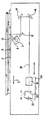
図1に典型的な光学スキャナの概略断面図を示す。光源によってガラスプラテン4に載置された文書6が照射される。光源はランプ2、凹面鏡8及び赤外線フィルタ10からなる。文書6から反射された光は第1のミラー12、第2のミラー14及び第3のミラー16を有するスキャナの内部で順番に反射される。その後、この反射光はレンズアセンブリ18を通過して最後に光電センサ20に入射する。
【0004】
光電センサ20はホルダ22によって保持されている。センサホルダ22及びレンズアセンブリ18は可動光学キャリッジ24に取り付けられている。文書6の画像の読取り倍率は、光学キャリッジ24をモータ(図示せず)を用いてレンズアセンブリ18の光軸26上で移動することによって変化させることができる。
【0005】
一般的に、スキャナを梱包する際には、光学キャリッジが輸送中動かないようにロックしておく方がよい。これを行なわないと、光学キャリッジが動き回ってスキャナの光学要素が適切なアラインメントからずれたり、あるいはスキャナの要素に損傷が生じたりすることがある。しかし、警告ラベルを多数貼っておいても、スキャナの電源投入に先だって光学スキャナキャリッジのロックを解除しなければならないことを理解しないエンドユーザがある割合で存在する。これを行なわないとスキャナは動作しない。スキャナを開けてみて自分で問題を明らかにしようとするエンドユーザも存在するが、その結果エンドユーザが感電したりあるいは内部のスキャナ要素に静電気によるダメージが生じて不必要な返品が発生したりする。また、このようなエンドユーザの何パーセントかはメーカのサービスセンタに電話して、スキャナが動作しない理由を知ろうとするが、その結果不必要なサービス時間とフリーダイアルの使用によって年間に何万ドルもの経費が生じるおそれがある。さらに、スキャナの光学キャリッジを移動させるモータは、光学キャリッジがロック位置にあるときエンドユーザがスキャナを動作させようとすると焼損する可能性がある。
【0006】
従って、光学キャリッジがロック位置にあるときスキャナへの電源投入を防止することができれば有益である。さらに、スキャナの光学キャリッジをロックしまたロック状態を解除するシステムをうっかりして損層を与えるのを防ぐという利点がある。
【0007】
【課題を解決するための手段】
本発明の上記の側面及び他の側面は、スキャナの光学キャリッジがロック位置にあるとき電源コードのスキャナへの差し込みを防止するスキャナ用の改良された光学キャリッジロッキングシステムによって達成される。
【0008】
本発明の一実施例によれば、スキャナの光学キャリッジアセンブリがロック位置にあるときスキャナへの電力の投入を防止するスキャナ用の光学キャリッジロッキングシステムを設けている。この光学キャリッジロッキングシステムはロック位置にあるときスキャナの電源コードコンセントが電源コードを受け入れるのを妨害する電源コード締め出し部材を有する。電源コード締め出し部材はロック解除位置にあるときスキャナの電源コードコンセントが電源コードを受け入れることができるようにする。光学キャリッジロッキングシステムはさらにラッチ位置にあるときスキャナの光学キャリッジアセンブリがスキャナ内を移動することを防止するキャリッジラッチをする。このキャリッジラッチはスキャナの動作中にスキャナの光学キャリッジアセンブリがスキャナ内を意図した通りに移動できるようにする。電源コード締め出し部材及びキャリッジラッチは、キャリッジラッチがラッチ位置にあるとき電源コート締め出し部材がロック位置となり、キャリッジラッチがラッチ解除位置にあるとき電源コード締め出し部材がロック解除位置となるように取り付けられる。
【0009】
【発明の実施の形態】
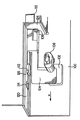
図2は電源コードコンセント102及びこの電源コードコンセント102への入口を覆うロック位置にある電源コード締め出し部材104を有するスキャナ筐体100のバックパネルを示す。電源コード締め出し部材104がロック位置にあるとき、電源コード106を電源コードコンセント102に差し込むことができず、従ってスキャナは電源を投入することができない。電源コード締め出し部材104はキャリッジラッチ110と一体になっている。電源コード締め出し部材104がロック位置にあるとき、キャリッジラッチ110はスキャナ筐体100の壁124の孔108から突出し、光学キャリッジアセンブリ(図3及び図5に示す)の移動を阻止する。
【0010】
ロッキング部材112もキャリッジラッチ110及び電源コード締め出し部材104と一体になっている。ロッキング部材112は、電源コード締め出し部材104がロック位置にあり、キャリッジラッチ110がラッチ位置にあるとき、スキャナ筐体100の壁120の孔122にロックされる。
【0011】
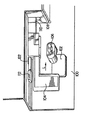
図3はスキャナ筐体100であって、キャリッジラッチ110を受け入れるスロット116を有する光学キャリッジアセンブリ118を示すために、スキャナ筐体100の内部の切取図によって図示している。キャリッジラッチ110がスキャナ筐体100の壁124の孔108及び光学キャリッジアセンブリ118のスロット116から突出するとき、光学アセンブリ118はラッチ位置にあり、スキャナ筐体内での移動は実質的に防止される。
【0012】
図2及び図3はスキャナ筐体100の壁120の孔122にロックされたロッキング部材112を示す。電源コードコンセント102が電源コード106を受け入れることができるように電源コード締め出し部材104のロックを解除し、スキャナの動作中に光学キャリッジアセンブリが意図した通りに移動しうるようにキャリッジラッチ110のラッチを解除するには、エンドユーザは電源コード締め出し部材104を矢印Uで示すように左に押すだけでよい。ロッキング部材112は傾斜部を有しており、光学キャリッジがロック解除位置に到達したとき、ロッキング部材112が孔122を容易に抜け出して左に摺動し、孔114に係合できるようになっている。
【0013】
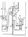
図4はロック解除位置にある電力コードコンセント102及び電源コード締め出し部材104を有するスキャナ筐体100のバックパネルを示している。図に示すロック解除状態では、電源コード106は電源コードコンセント102に到達できる。従って、電源コード106を電源コードコンセント102に容易に差し込むことができ、従ってスキャナに電源を投入することができる。電源コード締め出し部材104がロック解除位置にあるとき、キャリッジラッチ110はスキャナ筐体100の壁124の孔108から突出せず、これにより光学キャリッジアセンブリのスロット116(図5に示す)に到達して光学キャリッジアセンブリの移動を阻止することもない。従って、電源コード106を電源コードコンセント102に差し込むことができるときには、光学キャリッジ118(図5に示す)はラッチが解除されてスキャナの動作中にスキャナ筐体100内で意図された通りに自由に移動することができる。
【0014】
電源コード締め出し部材104がロック解除位置にあり、キャリッジラッチ110がラッチ解除位置にあるとき、ロッキング部材112はスキャナ筐体100の壁120の孔114にロックされる。
【0015】
図5はスキャナ筐体100であり、キャリッジラッチ110を受け入れるスロット116を有する光学キャリッジアセンブリ118を示すために、スキャナ筐体100の内部の切取図の形態で図示されている。電源コード締め出し部材104がロック解除位置にあるとき、キャリッジラッチ110がスキャナ筐体100の壁124の孔108から突出せず、これにより光学キャリッジアセンブリ118のスロット116を貫通して伸びることもない。従って、光学アセンブリ118はラッチ解除位置にあり、スキャナの動作中にスキャナ筐体100内で意図した通りに移動することができる。
【0016】
図4及び図5はスキャナ筐体100の壁120の孔114にロックされたロッキング部材112を示す。電源コード締め出し部材104をロック解除位置からロック位置に移動させて電源コードコンセント102が電源コード106を受け入れるのを阻止し、スキャナ筐体100内での光学キャリッジアセンブリの移動を実質的に防止するには、エンドユーザは電源コード締め出し部材を矢印Lで示すように右に押すだけでよい。ロッキング部材112は傾斜部を有しており、光学キャリッジがロック位置に到達したとき、孔114を容易に抜け出して右に摺動し、孔122に係合するようになっている。
【0017】
電源コード締め出し部材104、キャリッジラッチ110及びロッキング部材112の一体になった要素は、プラスティックあるいは金属といった任意の弾性力の大きな材料で製作することができる。好適にはこの要素全体はABS-PC配合物等のプラスティックで一体に作成された部材であるが、異なる材料を結合して一体のユニットとすることもできる。
【0018】
他の実施例は、ばね負荷された電源コード締め出し部材104及びキャリッジラッチ110を含む一体になったロッキング要素を有し、電源コード106が電源コードコンセント102に入っていないとき、電源コード締め出し部材104及びキャリッジラッチ110を構成するこの一体のロッキング要素が自動的にロック/ラッチ位置となる。このような実施例においては、スキャナは、電源を切ったとき、電源コード106が電源コードコンセント102から取り外された場合には光学キャリッジラッチ110がキャリッジをラッチしうるように、光学キャリッジ118をラッチ可能位置に戻さなければならない。従って、エンドユーザがスキャナを新たな場所に移動するかあるいは輸送する必要がある場合、電源コード106を電源コードコンセント102から取り外したときには、光学キャリッジアセンブリ118のスキャナ筐体100内での移動が自動的に防止される。従って、スキャナを移動する際に、光学キャリッジアセンブリがスキャナ筐体100内の光学要素あるいは電気的要素を破壊したり、これに衝突したりすることが防止される。
【0019】
本発明の以上の説明は図示及び説明の目的で行なったものであり、本発明を網羅しようとするものではなく、また本発明をここに開示した形態に厳密に限定しようとするものでもなく、上述の原理に照らした他の改変が可能である。たとえば、電源コード締め出し部材104及びキャリッジラッチ110からなる一体のロッキング要素はロッキング部材112を用いてロックする必要はなく、電源コードコンセントの端部、光学キャリッジアセンブリ118の端部、光学キャリッジアセンブリ118のスロット116、スキャナ筐体100の孔108といった他の何らかの手段、何らかのばね力、あるいは他の何らかの既知の手段を用いてロックすることができる。
【0020】
上記の実施形態は、本発明の原理及びその実際の応用について最良の説明を加えることによって、当業者がその意図する特定の用途に適した様々な実施形態及び様々な変更形態で本発明を最も有効に利用しうるように選択及び説明したものである。特許請求の範囲は、従来技術によって限定されるものを除き本発明の他の代替的実施形態を含むものと解釈すべきものである。
【0021】
以下日本発明の実施の態様の例を列挙する。
【0022】
〔実施態様1〕以下の(a)及び(b)を設け、スキャナの光学キャリッジアセンブリ118がロック位置にあるとき前記スキャナへの電源投入を防止するスキャナ用の光学キャリッジロッキングシステム:
(a) ロック位置にあるとき前記スキャナの電源コードコンセント102が電源コード106を受け入れることを防止する電源コード締め出し部材104:前記電源コード締め出し部材104はロック解除位置にあるとき前記スキャナの前記電源コードコンセント102が電源コード106を受け入れることができるようにする;
(b) ラッチ位置にあるとき前記スキャナの前記光学キャリッジアセンブリ118が前記スキャナ内を移動することを防止するキャリッジラッチ110:前記キャリッジラッチ110はスキャナの動作中に前記スキャナの前記光学キャリッジアセンブリ118が前記スキャナ内を意図した通りに移動できるようにし、前記電源コード締め出し部材104及び前記キャリッジラッチ110は、前記キャリッジラッチ110がラッチ位置にあるとき前記電源コート締め出し部材104がロック位置となり、前記キャリッジラッチ110がラッチ解除位置にあるとき前記電源コード締め出し部材104がロック解除位置となるように取り付けられる。
【0023】
〔実施態様2〕ロック解除されるまで前記電源コード締め出し部材104をロック位置に、前記キャリッジラッチ110をラッチ位置に維持するロッキング部材112を含むことを特徴とする実施態様1記載の光学キャリッジロッキングシステム。
【0024】
〔実施態様3〕前期電源コード106が前記電源コードコンセント102に挿入されているとき、前記キャリッジラッチ110が常にラッチ位置にあり、前記光学キャリッジアセンブリ118の前記スキャナ内での移動が常に防止されるようにばね荷重されたロッキング部材112を含むことを特徴とする実施態様1記載の光学キャリッジロッキングシステム。
【図面の簡単な説明】
【図1】典型的なイメージセンサーの概略断面図。
【図2】電源コード及びロック位置にある本発明に係る光学キャリッジロッキング機構を有するスキャナ筐体の概略図。
【図3】電源コード及びロック位置にある本発明に係る光学キャリッジロッキング機構を有するスキャナ筐体及び光学キャリッジの概略図。
【図4】電源コード及びロック解除位置にある本発明に係る光学キャリッジロッキング機構を有するスキャナ筐体の概略図。
【図5】電源コード及びロック解除位置にある本発明に係る光学キャリッジロッキング機構を有するスキャナ筐体及び光学キャリッジの概略図。
【符号の説明】
2:ランプ
4:ガラスプラテン
6:文書
8:凹面鏡
10:赤外線フィルタ
12:第1のミラー
14:第2のミラー
16:第3のミラー
18:レンズアセンブリ
20:光電センサ
22:ホルダ
24:可動光学キャリッジ
26:光軸
100:スキャナ筐体
102:電源コードコンセント
104:電源コード締め出し部材
106:電源コード
108:孔
110:キャリッジラッチ
112:ロッキング部材
114:孔
116:スロット
118:光学キャリッジアセンブリ
120, 124:壁
122:孔[0001]
BACKGROUND OF THE INVENTION
The present invention relates generally to the field of optical scanners, and more particularly to a locking system that prevents scanner power-up when an optical carriage assembly is in a locked position.
[0002]
[Prior art and its problems]
Optical scanners are used to capture and digitize images. For example, an image of what is printed on a paper sheet can be captured using an optical scanner. The digitized image can then be electronically stored and / or processed using character recognition software to generate ASCII text that can be sent to a computer screen or printer. Conventional optical scanners include light sources, various lenses, mirrors and other optical elements, linear arrays of photoelectric sensing elements such as CCD arrays, optical carriage assemblies, motors, analog amplifiers, analog / digital converters, controllers and random access memory (RAM). ).
[0003]
FIG. 1 shows a schematic cross-sectional view of a typical optical scanner. A document 6 placed on the
[0004]
The photoelectric sensor 20 is held by a
[0005]
In general, when packing a scanner, it is better to lock the optical carriage so that it does not move during transport. If this is not done, the optical carriage may move around and the optical elements of the scanner may deviate from proper alignment, or the elements of the scanner may be damaged. However, even with a large number of warning labels, there is a certain percentage of end users who do not understand that the optical scanner carriage must be unlocked before the scanner is turned on. If this is not done, the scanner will not work. Some end users try to open the scanner and try to clarify the problem themselves, but as a result, the end user may get an electric shock, or internal scanner elements may be damaged by static electricity, resulting in unnecessary returns. . Also, some percent of these end-users call the manufacturer's service center to find out why the scanner is not working, resulting in tens of thousands of dollars per year due to unnecessary service time and free dial usage. There is a risk of incurring costs. Further, the motor that moves the optical carriage of the scanner may burn out if the end user attempts to operate the scanner when the optical carriage is in the locked position.
[0006]
Therefore, it would be beneficial if power to the scanner could be prevented when the optical carriage is in the locked position. In addition, there is the advantage that the system that locks and unlocks the optical carriage of the scanner is inadvertently prevented from being damaged.
[0007]
[Means for Solving the Problems]
The above and other aspects of the present invention are achieved by an improved optical carriage locking system for a scanner that prevents the insertion of a power cord into the scanner when the optical carriage of the scanner is in the locked position.
[0008]
According to one embodiment of the present invention, an optical carriage locking system for a scanner is provided that prevents power from being applied to the scanner when the optical carriage assembly of the scanner is in the locked position. The optical carriage locking system has a power cord clamp member that prevents the scanner power cord outlet from accepting the power cord when in the locked position. The power cord clamp member allows the scanner power cord outlet to accept the power cord when in the unlocked position. The optical carriage locking system further includes a carriage latch that prevents the optical carriage assembly of the scanner from moving through the scanner when in the latched position. The carriage latch allows the optical carriage assembly of the scanner to move as intended within the scanner during scanner operation. The power cord locking member and the carriage latch are attached such that the power cord locking member is in the locked position when the carriage latch is in the latched position, and the power cord locking member is in the unlocked position when the carriage latch is in the latch released position.
[0009]
DETAILED DESCRIPTION OF THE INVENTION
FIG. 2 shows a back panel of the
[0010]
The
[0011]
FIG. 3 illustrates the
[0012]
2 and 3 show the
[0013]
FIG. 4 shows the back panel of the
[0014]
When the power
[0015]
FIG. 5 is a
[0016]
4 and 5 show the locking
[0017]
The integrated element of the power
[0018]
Another embodiment has an integral locking element that includes a spring loaded power
[0019]
The foregoing description of the present invention has been presented for purposes of illustration and description, and is not intended to be exhaustive or to limit the invention to the precise form disclosed herein. Other modifications in light of the above principles are possible. For example, the integral locking element comprising the power
[0020]
The above embodiments have best described the invention in various embodiments and various modifications suitable for the particular application intended by those skilled in the art by adding the best description of the principles of the invention and its practical application. It is selected and explained so that it can be used effectively. The claims are to be construed to include other alternative embodiments of the invention except insofar as limited by the prior art.
[0021]
Examples of embodiments of the Japanese invention are listed below.
[0022]
[Embodiment 1] An optical carriage locking system for a scanner which is provided with the following (a) and (b) and prevents the scanner from being turned on when the
(a) A power
(b)
[0023]
[Embodiment 2] The optical carriage locking system according to embodiment 1, further comprising a locking
[0024]
[Embodiment 3] When the
[Brief description of the drawings]
FIG. 1 is a schematic cross-sectional view of a typical image sensor.
FIG. 2 is a schematic view of a scanner housing having a power cord and an optical carriage locking mechanism according to the present invention in a locked position.
FIG. 3 is a schematic view of a scanner housing and an optical carriage having an optical carriage locking mechanism according to the present invention in a power cord and a locking position.
FIG. 4 is a schematic view of a scanner housing having an optical carriage locking mechanism according to the present invention in a power cord and an unlock position.
FIG. 5 is a schematic view of a scanner housing and an optical carriage having an optical carriage locking mechanism according to the present invention in a power cord and an unlock position.
[Explanation of symbols]
2: Lamp
4: Glass platen
6: Document
8: Concave mirror
10: Infrared filter
12: First mirror
14: Second mirror
16: Third mirror
18: Lens assembly
20: Photoelectric sensor
22: Holder
24: Movable optical carriage
26: Optical axis
100: Scanner housing
102: Power cord outlet
104: Power cord locking member
106: Power cord
108: Hole
110: Carriage latch
112: Locking member
114: Hole
116: Slot
118: Optical carriage assembly
120, 124: Wall
122: Hole
Claims (3)
(b)(b) ラッチ位置にあるとき、前記スキャナの光学キャリッジアセンブリが前記スキャナ内を移動することを防止し、ラッチ解除位置にあるとき、前記スキャナの前記光学キャリッジアセンブリが前記スキャナの動作中に前記スキャナ内を意図した通りに移動できるようにしたキャリッジラッチと、When in the latched position, prevents the optical carriage assembly of the scanner from moving through the scanner, and when in the unlatched position, the optical carriage assembly of the scanner is intended within the scanner during operation of the scanner. A carriage latch that can be moved as
を設け、前記キャリッジラッチがラッチ位置にあるとき、前記電源コート締め出し部材がロック位置となり、前記キャリッジラッチがラッチ解除位置にあるとき、前記電源コード締め出し部材がロック解除位置となるように、前記電源コード締め出し部材と前記キャリッジラッチが取り付けられていることを特徴とするスキャナの光学キャリッジアセンブリがロック位置にあるときスキャナへの電源投入を防止する光学キャリッジロッキング装置。And when the carriage latch is in the latched position, the power supply cord lockout member is in the lock position, and when the carriage latch is in the latch release position, the power cord lockout member is in the lock release position. An optical carriage locking device for preventing power supply to the scanner when the optical carriage assembly of the scanner is in a locked position, wherein the cord locking member and the carriage latch are attached.
Applications Claiming Priority (2)
| Application Number | Priority Date | Filing Date | Title |
|---|---|---|---|
| US769,334 | 1996-12-19 | ||
| US08/769,334 US5767977A (en) | 1996-12-19 | 1996-12-19 | Method and apparatus for a carriage latch and power cord lock-out system for an optical scanner |
Publications (2)
| Publication Number | Publication Date |
|---|---|
| JPH10221623A JPH10221623A (en) | 1998-08-21 |
| JP3933282B2 true JP3933282B2 (en) | 2007-06-20 |
Family
ID=25085143
Family Applications (1)
| Application Number | Title | Priority Date | Filing Date |
|---|---|---|---|
| JP35040897A Expired - Fee Related JP3933282B2 (en) | 1996-12-19 | 1997-12-19 | Locking system |
Country Status (5)
| Country | Link |
|---|---|
| US (1) | US5767977A (en) |
| EP (1) | EP0851657B1 (en) |
| JP (1) | JP3933282B2 (en) |
| DE (1) | DE69719303T2 (en) |
| TW (1) | TW374886B (en) |
Families Citing this family (14)
| Publication number | Priority date | Publication date | Assignee | Title |
|---|---|---|---|---|
| GB9602080D0 (en) * | 1996-02-02 | 1996-04-03 | Pfizer Ltd | Pharmaceutical compounds |
| US5926671A (en) * | 1998-08-07 | 1999-07-20 | Xerox Corporation | Integral multi-function latch |
| US6247374B1 (en) * | 1999-05-13 | 2001-06-19 | Mustek Systems Inc. | Locking mechanism for automatically immobilizing a carriage of a scanner at a rest position |
| JP2001197259A (en) * | 2000-01-13 | 2001-07-19 | Fuji Photo Optical Co Ltd | Carriage fixing structure for image reader |
| US6476373B1 (en) * | 2001-04-12 | 2002-11-05 | Hewlett-Packard Company | Method and apparatus for securing a flatbed scanner carriage |
| TW543320B (en) * | 2001-12-27 | 2003-07-21 | Veutron Corp | Moveable locking device for scanner and the locking method |
| US7068401B2 (en) * | 2002-05-31 | 2006-06-27 | Hewlett-Packard Development Company, L.P. | Optical scanning apparatus having a carriage locking device |
| US7433090B2 (en) * | 2003-01-28 | 2008-10-07 | Murray David K | Print/scan assembly and printer apparatus and methods including the same |
| US7133145B2 (en) * | 2003-02-05 | 2006-11-07 | Hewlett-Packard Development Company, L.P. | Method and assembly for carriage locking |
| US6824055B2 (en) * | 2003-04-01 | 2004-11-30 | Hewlett-Packard Development Company, L.P. | System and method for securing a scanner carriage |
| US7724276B2 (en) * | 2003-11-03 | 2010-05-25 | Hewlett-Packard Development Company, L.P. | Optical assembly lock/unlock apparatus and method |
| US20060061832A1 (en) * | 2004-09-17 | 2006-03-23 | Christa Ferguson | Method to unlock scanner carriage without user intervention |
| US7229106B2 (en) * | 2005-07-27 | 2007-06-12 | Xerox Corporation | Latch |
| JP5327798B2 (en) | 2009-06-25 | 2013-10-30 | ニスカ株式会社 | Optical reader |
Family Cites Families (9)
| Publication number | Priority date | Publication date | Assignee | Title |
|---|---|---|---|---|
| US3728586A (en) * | 1972-01-07 | 1973-04-17 | Hewlett Packard Co | Ac power module having an integral mechanical safety device |
| US4167658A (en) * | 1978-03-20 | 1979-09-11 | Sherman Robert S | Safety and security outlet |
| US4596908A (en) * | 1985-03-05 | 1986-06-24 | Mott John S | Safety cover for an electrical outlet |
| US4916550A (en) * | 1988-02-05 | 1990-04-10 | Fuji Photo Film Co., Ltd. | Foldable portable optical instrument |
| JPH0268576A (en) * | 1988-09-05 | 1990-03-08 | Canon Inc | Safety mechanism for copying device |
| JPH0290857A (en) * | 1988-09-28 | 1990-03-30 | Toshiba Corp | Information reader |
| US5344331A (en) * | 1993-01-15 | 1994-09-06 | Hubbell Incorporated | Electrical connector system, especially for electric vehicles |
| US5535096A (en) * | 1995-01-27 | 1996-07-09 | Universities Research Association, Inc. | Safety lock-out device for electrical appliances |
| JPH0983695A (en) * | 1995-09-09 | 1997-03-28 | Ricoh Co Ltd | Image forming device |
-
1996
- 1996-12-19 US US08/769,334 patent/US5767977A/en not_active Expired - Lifetime
-
1997
- 1997-08-07 TW TW086111305A patent/TW374886B/en active
- 1997-11-18 EP EP97309277A patent/EP0851657B1/en not_active Expired - Lifetime
- 1997-11-18 DE DE69719303T patent/DE69719303T2/en not_active Expired - Fee Related
- 1997-12-19 JP JP35040897A patent/JP3933282B2/en not_active Expired - Fee Related
Also Published As
| Publication number | Publication date |
|---|---|
| EP0851657A3 (en) | 1999-12-22 |
| EP0851657B1 (en) | 2003-02-26 |
| DE69719303D1 (en) | 2003-04-03 |
| JPH10221623A (en) | 1998-08-21 |
| EP0851657A2 (en) | 1998-07-01 |
| US5767977A (en) | 1998-06-16 |
| TW374886B (en) | 1999-11-21 |
| DE69719303T2 (en) | 2003-11-20 |
Similar Documents
| Publication | Publication Date | Title |
|---|---|---|
| JP3933282B2 (en) | Locking system | |
| US7068401B2 (en) | Optical scanning apparatus having a carriage locking device | |
| US7808688B2 (en) | Apparatus and method of capturing images from alternative media types | |
| EP1026620B1 (en) | Expandable hand scanner with lens reduction optics | |
| US20050031390A1 (en) | Image capture device with a telescopic hinge | |
| US7626739B2 (en) | Imaging using media carriage coupled to a lid | |
| US7133145B2 (en) | Method and assembly for carriage locking | |
| US6937368B2 (en) | Locking device for a movable module of an apparatus | |
| EP0959610A3 (en) | Imaging apparatus for a photographic film image scanner | |
| CN211173469U (en) | Double-opening lock | |
| US6824055B2 (en) | System and method for securing a scanner carriage | |
| GB2218727A (en) | Telephone socket lock | |
| US6008501A (en) | Apparatus and method for automatically detecting presence of a scanned document | |
| US11310385B1 (en) | Portable cassette locker for document handler | |
| US7012234B2 (en) | Apparatus and method for capturing oversize images for imaging devices | |
| JP3764072B2 (en) | Method for detecting locked state of document reading device | |
| TWI379937B (en) | Security system | |
| US20020140874A1 (en) | Carriage fixing screw housing structure | |
| JP3541721B2 (en) | Fixing means for image reading device | |
| JPH03174869A (en) | Picture reader | |
| CN1256468A (en) | Transparent platform scanner | |
| JP2000292868A (en) | Film holder and system using it | |
| JPH11331519A (en) | Carriage fixing device | |
| JPH09222679A (en) | Image input device | |
| JPH0543111A (en) | Document storage mechanism for electronic file and the like |
Legal Events
| Date | Code | Title | Description |
|---|---|---|---|
| RD03 | Notification of appointment of power of attorney |
Free format text: JAPANESE INTERMEDIATE CODE: A7423 Effective date: 20040318 |
|
| RD04 | Notification of resignation of power of attorney |
Free format text: JAPANESE INTERMEDIATE CODE: A7424 Effective date: 20040319 |
|
| A521 | Request for written amendment filed |
Free format text: JAPANESE INTERMEDIATE CODE: A523 Effective date: 20040430 |
|
| A621 | Written request for application examination |
Free format text: JAPANESE INTERMEDIATE CODE: A621 Effective date: 20040430 |
|
| TRDD | Decision of grant or rejection written | ||
| A01 | Written decision to grant a patent or to grant a registration (utility model) |
Free format text: JAPANESE INTERMEDIATE CODE: A01 Effective date: 20070220 |
|
| A61 | First payment of annual fees (during grant procedure) |
Free format text: JAPANESE INTERMEDIATE CODE: A61 Effective date: 20070313 |
|
| R150 | Certificate of patent or registration of utility model |
Free format text: JAPANESE INTERMEDIATE CODE: R150 |
|
| FPAY | Renewal fee payment (event date is renewal date of database) |
Free format text: PAYMENT UNTIL: 20100330 Year of fee payment: 3 |
|
| FPAY | Renewal fee payment (event date is renewal date of database) |
Free format text: PAYMENT UNTIL: 20110330 Year of fee payment: 4 |
|
| LAPS | Cancellation because of no payment of annual fees |