JP3929956B2 - Pen-type projection display - Google Patents
Pen-type projection display Download PDFInfo
- Publication number
- JP3929956B2 JP3929956B2 JP2003338671A JP2003338671A JP3929956B2 JP 3929956 B2 JP3929956 B2 JP 3929956B2 JP 2003338671 A JP2003338671 A JP 2003338671A JP 2003338671 A JP2003338671 A JP 2003338671A JP 3929956 B2 JP3929956 B2 JP 3929956B2
- Authority
- JP
- Japan
- Prior art keywords
- unit
- projection
- light
- optical
- vibrates
- Prior art date
- Legal status (The legal status is an assumption and is not a legal conclusion. Google has not performed a legal analysis and makes no representation as to the accuracy of the status listed.)
- Expired - Fee Related
Links
Images


Classifications
-
- G—PHYSICS
- G06—COMPUTING; CALCULATING OR COUNTING
- G06F—ELECTRIC DIGITAL DATA PROCESSING
- G06F3/00—Input arrangements for transferring data to be processed into a form capable of being handled by the computer; Output arrangements for transferring data from processing unit to output unit, e.g. interface arrangements
- G06F3/01—Input arrangements or combined input and output arrangements for interaction between user and computer
- G06F3/03—Arrangements for converting the position or the displacement of a member into a coded form
- G06F3/033—Pointing devices displaced or positioned by the user, e.g. mice, trackballs, pens or joysticks; Accessories therefor
- G06F3/0354—Pointing devices displaced or positioned by the user, e.g. mice, trackballs, pens or joysticks; Accessories therefor with detection of 2D relative movements between the device, or an operating part thereof, and a plane or surface, e.g. 2D mice, trackballs, pens or pucks
-
- B—PERFORMING OPERATIONS; TRANSPORTING
- B43—WRITING OR DRAWING IMPLEMENTS; BUREAU ACCESSORIES
- B43K—IMPLEMENTS FOR WRITING OR DRAWING
- B43K29/00—Combinations of writing implements with other articles
-
- B—PERFORMING OPERATIONS; TRANSPORTING
- B43—WRITING OR DRAWING IMPLEMENTS; BUREAU ACCESSORIES
- B43K—IMPLEMENTS FOR WRITING OR DRAWING
- B43K29/00—Combinations of writing implements with other articles
- B43K29/10—Combinations of writing implements with other articles with illuminating devices
-
- G—PHYSICS
- G06—COMPUTING; CALCULATING OR COUNTING
- G06F—ELECTRIC DIGITAL DATA PROCESSING
- G06F3/00—Input arrangements for transferring data to be processed into a form capable of being handled by the computer; Output arrangements for transferring data from processing unit to output unit, e.g. interface arrangements
- G06F3/01—Input arrangements or combined input and output arrangements for interaction between user and computer
- G06F3/03—Arrangements for converting the position or the displacement of a member into a coded form
-
- H—ELECTRICITY
- H04—ELECTRIC COMMUNICATION TECHNIQUE
- H04N—PICTORIAL COMMUNICATION, e.g. TELEVISION
- H04N9/00—Details of colour television systems
- H04N9/12—Picture reproducers
- H04N9/14—Picture reproducers using optical-mechanical scanning means only
-
- H—ELECTRICITY
- H04—ELECTRIC COMMUNICATION TECHNIQUE
- H04N—PICTORIAL COMMUNICATION, e.g. TELEVISION
- H04N9/00—Details of colour television systems
- H04N9/12—Picture reproducers
- H04N9/31—Projection devices for colour picture display, e.g. using electronic spatial light modulators [ESLM]
- H04N9/3129—Projection devices for colour picture display, e.g. using electronic spatial light modulators [ESLM] scanning a light beam on the display screen
Description
(発明の分野)
本発明は、映写(projection)ディスプレーに関する。本発明は、特に、インク式ペンまたはコンピュータ用スタイラスといった、携帯用筆記器具に組み入れることができる映写ディスプレーへの適用性を有する。
(Field of Invention)
The present invention relates to a projection display. The invention has particular applicability to projection displays that can be incorporated into portable writing instruments such as ink pens or computer styluses.
(本発明の背景)
コンピュータは、私たちの社会において、ユビキタスになりつつあり、日常生活のあらゆる面において使用されている。現代のコンピュータは、ユーザが聞き取れるように情報を提供し、殆どのコンピュータのために伝達される情報の主流は、視覚に訴えるものである。それは、殆どのコンピュータが、ユーザに対して、CRT(Cathode Ray Tube:陰極線管)モニター、液晶表示モニターまたはプラズマモニターなど、モニター上に情報を視覚的に表示する。
(Background of the present invention)
Computers are becoming ubiquitous in our society and are used in all aspects of everyday life. Modern computers provide information that is audible to the user, and the mainstream of information transmitted for most computers is visually appealing. Most computers visually display information to a user on a monitor, such as a CRT (Cathode Ray Tube) monitor, a liquid crystal display monitor, or a plasma monitor.
したがって、コンピュータの処理部品および記憶部品が非常に小さく作られるようになる一方で、通常のコンピュータのサイズを更に小型化することは、表示モニターが視覚性を有する必要性から、事実上制限される。それ故、コンピュータによって提供された情報を快適に表示することができ、広い固定場所を占有しない、小型の表示モニターに対する要求がある。 Therefore, while the processing and storage components of the computer will be made very small, further downsizing of the normal computer is practically limited due to the need for the display monitor to be visual . Therefore, there is a need for a small display monitor that can comfortably display information provided by a computer and does not occupy a large fixed location.
(発明の概要)
本発明は、利点として、コンピュータからの画像情報に対応する画像など、画像を反射面に表示することができる映写ディスプレーを目的とする。本発明による映写ディスプレーによって表示された映像は、十分に大きく読みやすい一方で、映写ディスプレーの部品は、インク式ペンまたはデジタルタブレット用のスタイラスといった、携帯用筆記器具の内部に取り付けられるように十分に小さく作ることができる。
(Summary of Invention)
The present invention has as an advantage a projection display capable of displaying an image such as an image corresponding to image information from a computer on a reflecting surface. While the image displayed by the projection display according to the present invention is sufficiently large and easy to read, the components of the projection display are sufficient to be mounted inside a portable writing instrument such as an ink pen or a stylus for a digital tablet. Can be made small.
本発明の映写ディスプレーによれば、発振器は、光映写機によって映写される光を振動(注、光の向きをかえること)させる。さらに詳細には、発振器は、第1の方向および第1の方向に直交する第2の方向に、映写(投影)される光を同時に振動させる。例えば、発振器は、X軸方向およびY軸方向の両方向に、映写される光を同時に振動させる。この方法では、光映写機によって映写される光は、ラスタパターンで反射面を走査する。同時に、映写される光は、画像データに基づいて、ラスタスキャン処理と同期して変調される。したがって、映写される光は、変調および振動されて、走査範囲に、画像データに対応する画像を生成する。続く好ましい実施形態の詳細な説明もちろん、前述の発明の概要は、対応する図面を参照して読まれた時により良く理解される。 According to the projection display of the present invention, the oscillator vibrates (notes, changes the direction of the light) the light projected by the projector. More specifically, the oscillator causes the projected (projected) light to vibrate simultaneously in a first direction and a second direction orthogonal to the first direction. For example, the oscillator vibrates projected light simultaneously in both the X-axis direction and the Y-axis direction. In this method, the light projected by the light projector scans the reflection surface with a raster pattern. At the same time, the projected light is modulated in synchronization with the raster scan process based on the image data. Therefore, the projected light is modulated and vibrated to generate an image corresponding to the image data in the scanning range. DETAILED DESCRIPTION OF THE PREFERRED EMBODIMENTS Following, of course, the foregoing summary of the invention will be better understood when read with reference to the corresponding drawings.
(好ましい実施形態の詳細な説明)
(概観)
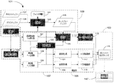
図1は、本発明の一実施形態の映写ディスプレー101を示す。図示するように、映写ディスプレー101は、光を発し映写するための光映写部103、光映写部103から映写される光を発振するための発振部105および、周波数生成・変調部107を含む。また、映写ディスプレー101は、画像データ入力部109および制御部111を含む。以下で詳細に説明するように、周波数生成・変調部107は、発振部105を駆動し、かつ光映写部103によって映写される光を変調する。次に、発振部105は、光映写部103によって映写される光を2次元に振動する。
Detailed Description of Preferred Embodiments
(Overview)
FIG. 1 shows a
さらに詳細には、発振部105は、光映写部103によって発せられる光を振動して、映写される光がラスタパターンで反射面を走査する。同時に、周波数生成・変調部107は、走査処理および画像データ入力部109によって供給された画像データと同期して、光映写部103によって発せられる光を変調する。この方式では、映写される光は、変調かつ振動されて、走査範囲に、画像データに対応する画像を描く。制御部111は、周波数生成・変調部107および画像データ入力部109の作動を制御する。
More specifically, the oscillating
図1に示されたように、光映写部103は、光を発する光源113および、光源113からの光を伝達する光伝達装置115を含む。以下で詳細に説明するように、光源113から映写される光は、個別のピクセル(画素)を形成するように変調されて、白紙、ホワイトボードまたは卓上といった反射面上を走査される。このように、幅が狭く焦点の合ったビームを映写する光源113は、幅が広くてより分散したビームを映写する光源113と比べて、より高いディスプレー解像度を提供する。したがって、図示の本発明の実施形態では、光源113は、約650nmの中心波長を有するレーザダイオードである。レーザダイオードが、都合よく、焦点の合ったコヒーレント(可干渉)な光のビームを映写し、映写ディスプレー101が高解像度で個別のピクセルを表示することができるということは、当業者によって理解されるであろう。
As shown in FIG. 1, the
図5に示すように、実施形態を図示した光伝達装置115は、光ファイバ115Aおよびレンズ115Bの組合せである。光ファイバ115Aは、レーザダイオード113から発される光を、光ファイバ115Aが曲げられている方向に、映写する。それは、レーザダイオード113自体が実際に動いて方向を変えることなく、光ファイバ115Aが、レーザダイオード113から発せられる光が様々な方向に映写されることを可能にする、ということである。代わりに、単純に光ファイバ115Aを特定の方向に向けて曲げるだけで、光ダイオード113から発せられる光は、その方向に映写される。レンズ115Bは、光ファイバ115Aによって伝送されて映写される光のビームの幅の細さを整える。図示された実施形態では、光ファイバ115Aは、約12mmの長さである。以下で詳細に述べるが、光ファイバ115Aの長さは、光ファイバ115Aが振動される周波数に依存して変化するかもしれない。
As shown in FIG. 5, the
本発明の別の実施形態では、光源113については、他の種類の機構を用いて実装することもできることに留意されたい。例えば、光源113は、いずれか適切な可視波長または複数波長の光を供給するレーザダイオードを用いて実装することもできる。光源113は、また、ガスレーザまたは固体レーザなど、他の種類のコヒーレントな光発生装置を用いて実装することもできる。光源113は、一般的な白熱光、蛍光またはLED(発光ダイオード)といった非コヒーレントな光装置を用いても実装することができる。本発明の実施についての上記内容から、光源113は、希望の距離に、希望の解像度で、個々のピクセルを描くことができる程度に十分に細い光のビームを発することができる必要があるのみであると理解されたい。
Note that in other embodiments of the present invention, the
同様に、光伝達装置115は、別の機構を用いて実装することができる。例えば、本発明のいくつかの実施形態では、光伝達装置115は、1または複数のレンズを用いて、光ファイバ115Aの使用を省略して、実装されることができる。光伝達装置115は、両方を省略されることさえできる。例えば、以下で詳細に述べるように、本発明の一部の実施形態は、光伝達装置115を振動させるのではなく、光源113を直接振動させることができる。これらの実施形態では、光伝達装置115は、必要ではなく、したがって、本発明のこれらの実施形態では提供されない。
Similarly, the
映写ディスプレー101が、携帯可能な形状で構成されている場合には、光源113からの光は、不注意で、使用者または使用者の近くにいる誰かの目に映写される場合がある。したがって、光源113は、有益的に、人間の目で安全に見ることができる小さいパワーの光源で実装する場合もある。例えば、図示の実施形態では、レーザダイオード113は、650nmの波長の光を映写し、20mA以下の動作電流を有する。映写される光が、光ファイバ115Aおよびレンズ115Bによって伝達された後、映写される光の出力電力は、約1mWである。もちろん、代わりに、人間の目に安全な光を映写する他の低電力の構成を、採用することができる。
When the
(発振部)
発振部105に関して、発振部は、X方向振動部117およびY方向振動部119を含む。波形発生器(wave generator)121は、X方向振動部117を駆動するための波形信号を生成し、他方、波生成器123は、Y方向振動部119を駆動する別の波形信号を生成する。X方向振動部117は、光伝達装置115の光ファイバ115Aに接続され、X方向振動部117が作動すると、波形発生器121によって生成された波形信号に対応する周波数で、X方向に光ファイバ115Aを振動させる。同様に、Y方向振動部119は、光伝達装置115の光ファイバ115Aに接続され、Y方向振動部119が作動されると、発振器123によって生成された波形信号に対応する周波数で、Y方向に光ファイバ115Aを振動させる。したがって、X方向振動部117およびY方向振動部119が、同時に作動する場合は、光伝達装置115の光ファイバ115Aは、X方向およびY方向の両方向に同時に振動する。
(Oscillator)
With respect to the oscillating
光ファイバ115AをY方向およびX方向の両方向に同時に、しかし十分に異なる周波数で、振動させることによって、光ファイバ115Aによって伝達される光は、反射面にラスタスキャンパターンを描く。もし光ファイバ115Aを、直交する方向に振動する早さよりも十分に早く一つの方向に振動した場合、光ファイバ115Aによって伝達される光は、光が映写される面をラスタ走査する。例えば、もし光ファイバ115Aが、光ファイバ115AがY方向に振動する割合の100倍の割合でX方向に振動する場合、光ファイバ115Aによって伝達される光は、Y方向に半分振動する間毎に、約50水平ラインを反射面に映写する。同様に、もし光ファイバ115Aが、光ファイバ115AがX方向に振動する割合の100倍の割合でY方向に振動する場合、光ファイバ115Aによって伝達される光は、X方向に半分振動する間毎に、約50垂直ラインを反射面に映写する。 By vibrating the optical fiber 115A in both the Y and X directions simultaneously, but with sufficiently different frequencies, the light transmitted by the optical fiber 115A draws a raster scan pattern on the reflective surface. If the optical fiber 115A is vibrated in one direction sufficiently faster than the rate of vibration in the orthogonal direction, the light transmitted by the optical fiber 115A raster scans the surface on which the light is projected. For example, if the optical fiber 115A vibrates in the X direction at a rate that is 100 times the rate that the optical fiber 115A vibrates in the Y direction, the light transmitted by the optical fiber 115A is every halfway vibrated in the Y direction. Approximately 50 horizontal lines are projected on the reflective surface. Similarly, if the optical fiber 115A vibrates in the Y direction at a rate that is 100 times the rate that the optical fiber 115A vibrates in the X direction, the light transmitted by the optical fiber 115A is every halfway in the X direction. In addition, about 50 vertical lines are projected on the reflecting surface.
図示の実施形態では、X方向振動部117およびY方向振動部119は、圧電セラミック発振器である。当業者に周知の通り、圧電発振器は、印加電圧の変化に比例して振動する。図示された実施形態では、波形発生器121によって生成された波形信号は、X方向振動部117を駆動操作する。同様に、波形発生器123によって生成された波形信号は、Y方向振動部119を駆動操作する。波形発生器121および123からの波形信号は、正弦波、三角波または他の適切な種類の波形の波とすることができる。波形発生器121および123からの波形信号の周波数は、次々に、周波数生成・変調部107によって供給される周波数信号に対応する。
In the illustrated embodiment, the
本発明の別の実施形態では、X方向振動部117およびY方向振動部119については、圧電セラミック発振器など、X方向およびY方向の両方向に振動する、一つの圧電発振器を用いて実装することができる。さらに、非圧電発振器を、光源113から映写される光を振動させるために使用することができる。例えば、誘導モータまたは他の種類の振動モータは、光源113から映写される光を振動させるために使用することができる。また、図示の実施形態では、発振部105は、光ファイバ115Aを振動させるが、本発明の別の実施形態として、光源113自体または光映写部103全体を、直接振動させることもできる。例えば、本発明の別の実施形態は、厳密な光伝達装置115を採用することができ、あるいは光伝達装置115の全てを省略することもできる。これらの実施形態では、光源113は、映写される光を振動させるために直接動かすことができる。本発明の実施形態の一例は、以下で詳細に説明する。
In another embodiment of the present invention, the X
ここで用いられる「X方向」および「Y方向」は、特定の方向を示すのではなく、単に、第2の方向に対する第1の方向の向きを示すために用いていると考慮されたい。当業者によって、走査処理が、映写される光を、いずれかの第1の方向および第1の方向に直交する第2の方向に、同時に動かすことによって実行されるということが、理解される。例えば、映写される光は、光映写部103をある軸について回転し、他方で同時に、(光源113または伝達装置115もしくは両方である)光映写部103をその軸と遠近方向に振動することによって、振動されることさえもできる。これらの実施形態では、映写される光は、X方向およびY方向に走査する本発明の実施形態におけるような直交座標ではなく、極座標に基づいたパターンで、反射面を走査する。
As used herein, “X direction” and “Y direction” do not indicate a specific direction, but are merely used to indicate the orientation of the first direction relative to the second direction. It will be appreciated by those skilled in the art that the scanning process is performed by simultaneously moving the projected light in either a first direction and a second direction orthogonal to the first direction. For example, the projected light rotates the
(周波数生成・変調部)
図1に示すように、周波数生成・変調部107は、周波数fの基準信号を生成する周波数発生器125を含む。変調周波数生成器127は、基準信号の周波数fに値mを乗算し、変調周波数fmの変調信号を生成する。以下でより詳細に述べるように、変調周波数fmは、光映写部103から映写される光によって走査される各々のラインにいくつのピクセルが発生するかを決定する。同様に、X方向振動周波数生成器129は、基準信号の周波数fに値xを乗算し、変調周波数fxのX方向振動信号を生成し、他方、Y方向振動周波数生成器131は、基準信号の周波数fに値yを乗算し、変調周波数fyのY方向振動信号を生成する。
(Frequency generator / modulator)
As shown in FIG. 1, the frequency generation /
X方向振動信号は、X方向振動部117の波形信号の周波数をX方向振動周波数fxに設定するために、波形発生器121に与えられる。Y方向振動信号は、Y方向振動部119の波形信号の周波数をY方向振動周波数fyに設定するために、波形発生器123に与えられる。このようにして、X方向振動部117は、X方向振動周波数生成器129によって生成されたX方向振動周波数fxで振動し、他方、Y方向振動部119は、Y方向振動周波数生成器131によって生成されたY方向振動周波数fyで振動する。本発明の別の実施形態では、周波数生成器129および131からの変調信号は、発振器117および119を直接に操作するのに十分に強力であることに留意されたい。したがって、これらの実施形態は、波形発生器121および123を省略することができる。
The X direction vibration signal is given to the
また、X方向振動信号、Y方向振動信号および変調信号は、同期制御部133に供給される。以下で詳細に説明するように、同期制御部133は、画像データ入力部109からの画像データをX方向振動信号および変調信号と同期させることで、走査ラインにおける各々のピクセルの位置に対応する画像データが用いて、光映写部103によって対応するピクセルの映写が変調されることを確実にする。同様に、同期制御部133は、画像データ入力部109からの画像データをY方向振動信号と同期させ、表示されるスクリーンにおける各々のピクセルの位置に対応したが画像データが、その対応するピクセルの映写に変調されて、光映写部103によって使用されることを確実にする。
Further, the X direction vibration signal, the Y direction vibration signal, and the modulation signal are supplied to the
(振動周波数および変調周波数の決定)
X方向振動周波数、Y方向振動周波数および変調周波数を決定するために、リフレッシュ周波数が最初に設定される。もし、表示された画像のリフレッシュレートが30Hz以下である場合に、人間の目はチラツキを感じるということが当業者によって理解される。したがって、本発明の様々な実施形態では、X方向振動周波数およびY方向振動周波数の両方は、典型的には、30Hzよりも高くなる。図示した実施形態では、映写された光は、X方向に平行に走査し、ラスタスキャンパターンのリフレッシュは、Y方向に映写された光の振動によってなされる。したがって、Y方向振動周波数は、図示された実施形態では、約80Hzに設定され、特に映写ディスプレー101が、ハンドヘルド装置内に用いられ、ユーザの手が揺れる場合に、チラツキがないことを保証する。もちろん、本発明の別の実施形態では、Y方向振動周波数は、80Hzよりも高くあるいは低くすることができる。さらに、もし対応するチラツキの量が、映写ディスプレー101の意図する使用に許容される場合には、Y方向振動周波数は、30Hzよりも低くすることさえできる。
(Determination of vibration frequency and modulation frequency)
In order to determine the X-direction vibration frequency, the Y-direction vibration frequency, and the modulation frequency, the refresh frequency is first set. It will be understood by those skilled in the art that the human eye feels flicker if the refresh rate of the displayed image is 30 Hz or less. Thus, in various embodiments of the present invention, both the X-direction vibration frequency and the Y-direction vibration frequency are typically higher than 30 Hz. In the illustrated embodiment, the projected light scans parallel to the X direction and the raster scan pattern is refreshed by the vibration of the light projected in the Y direction. Accordingly, the Y-direction vibration frequency is set to about 80 Hz in the illustrated embodiment, and in particular, the
図示された実施形態では、映写される光は、前に記載したように光伝達装置115の光ファイバ115Aを振動することによって、振動される。したがって、映写される光をラスタスキャン方向に振動する振動周波数を決定するために、光ファイバ115Aのための振動周波数を決定しなければならない。本発明の様々な実施形態では、光ファイバ115Aは、エネルギーの消費を削減し、一貫した振動を提供することができる高調波で振動される。
In the illustrated embodiment, the projected light is vibrated by vibrating the optical fiber 115A of the
当業者に知られているように、ラスタスキャン方向の光ファイバ115Aの一次モード振動、二次モード振動および高次モード振動の高調波振動周波数は、光ファイバ115Aの長さに関連している。より詳細には、ラスタスキャン方向に光ファイバ115Aを振動させるための、一次モードおよび二次モードの高調波振動周波数と光ファイバ115Aの長さの関係は、
oα1/l2
であり、ここで、oは、高調波振動周波数で、lは、振動中の光ファイバ115Aの長さである。長さlは、振動が始まる前の光ファイバ115Aの長さではない。光ファイバ115Aの長さは、光ファイバ115Aが振動するにしたがって伸びる。したがって、長さlは、最大限の長さに伸ばされた後の、振動中の光ファイバ115Aの長さに対応する。このように、高調波モードのX方向振動周波数を、光ファイバ115Aの与えられた長さから決定することができる。他に、光ファイバ115Aの長さを、希望した高調波モードの希望したX方向の高調波振動周波数に合うように決定することができる。
As known to those skilled in the art, the harmonic vibration frequencies of the first mode vibration, second order mode vibration and higher order mode vibration of the optical fiber 115A in the raster scan direction are related to the length of the optical fiber 115A. More specifically, the relationship between the harmonic vibration frequency of the primary mode and the secondary mode and the length of the optical fiber 115A for vibrating the optical fiber 115A in the raster scan direction is:
oα1 / l 2
Where o is the harmonic oscillation frequency and l is the length of the oscillating optical fiber 115A. The length l is not the length of the optical fiber 115A before vibration starts. The length of the optical fiber 115A increases as the optical fiber 115A vibrates. Accordingly, the length l corresponds to the length of the oscillating optical fiber 115A after being stretched to the maximum length. Thus, the X-direction vibration frequency of the harmonic mode can be determined from the given length of the optical fiber 115A. Alternatively, the length of the optical fiber 115A can be determined to match the desired harmonic vibration frequency in the X direction of the desired harmonic mode.
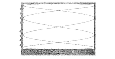
光ファイバ115Aを、いずれの高調波モードで、振動することができ、他方、高調波モードの振動を伴う光ファイバ115の長さは、光ファイバ115Aの移動範囲を決定することに留意されたい。この動作の範囲は、同様に、映写ディスプレー101の映写範囲を決定する。図2Aおよび2Bを参照すると、図2Aは、一次モードで振動している典型的な光ファイバ115Aの動作を示し、他方、図2Bは、二次モードで振動している典型的な光ファイバ115Aの動作を示す。このように、光ファイバ115Aは、一次モードまたは二次モード(ならびにより高次のモード)のいずれかで、光ファイバ115Aの長さおよび振動周波数に依存して、振動することができるが、二次モードで光ファイバ115Aを振動させることは、逆に、一次モードで光ファイバを振動させるよりも、より広い映写範囲を提供することができる。 二次モードの光ファイバの高調波周波数は、一次の高調波の約6倍であることが、当業者に理解される。したがって、与えられた周波数では、光ファイバの長さlは、二次モードの場合の振動に対する長さlよりも一次モードの場合の方がより短くなければならない。
It should be noted that the optical fiber 115A can be oscillated in any harmonic mode, while the length of the
図示の実施形態では、光ファイバ115Aは、約4.5Hzから5KHzのX方向振動周波数で、より広い映写範囲を確保するために、二次モードで振動される。したがって、光ファイバ115Aの長さlは、約12mmである。しかし、本発明の他の実施形態では、光ファイバ115Aは、一次モードで振動されることができる。これらの実施形態では、光ファイバ115Aの長さは、約4mmである。もちろん、より高いおよびより低い高調波周波数の双方および他の光ファイバの長さを、本発明の別の実施形態によって使用することができる。 In the illustrated embodiment, the optical fiber 115A is vibrated in the secondary mode to ensure a wider projection range at an X-directional vibration frequency of about 4.5 Hz to 5 KHz. Therefore, the length l of the optical fiber 115A is about 12 mm. However, in other embodiments of the invention, the optical fiber 115A can be oscillated in the first order mode. In these embodiments, the length of the optical fiber 115A is about 4 mm. Of course, both higher and lower harmonic frequencies and other optical fiber lengths can be used with other embodiments of the invention.
異なるスキャン周波数を、本発明の他の実施形態によって、選択的または付加的に使用することができる。走査方向の振動周波数が高いほど、映写ディスプレーの解像度が増加し、他方、走査方向の振動周波数が低いほど、映写ディスプレーの解像度が減少することが当業者に理解される。例えば、図3Aは、走査方向の振動周波数がリフレッシュ振動周波数の僅か4倍の時に、ディスプレー101によって映写されたラスタスキャンパターンを示し、他方、図3Bは、走査方向の振動周波数がリフレッシュ振動周波数の150倍の時に、ディスプレー101によって映写されたラスタスキャンパターンを示す。これらの図から解るように、図3Bに示されたラスタスキャンパターンは、図3Aに示されたラスタスキャンパターンよりも、その範囲でより多くの映写をカバーする。
Different scan frequencies can be used selectively or additionally according to other embodiments of the invention. It will be appreciated by those skilled in the art that the higher the oscillation frequency in the scanning direction, the higher the resolution of the projection display, while the lower the oscillation frequency in the scanning direction, the lower the resolution of the projection display. For example, FIG. 3A shows a raster scan pattern projected by the
(画像データ入力部)
図1を参照すると、映写ディスプレー101によって映写される画像データは、テキストバッファ137およびグラフバッファ139に起こる。より詳細には、映写ディスプレー101によって映写されるテキスト情報は、テキストバッファ137に格納される。線図など、他の型の画像データは、グラフバッファ139に格納される。テキストバッファ137に格納されるテキスト情報は、ASCIIコードのデータなど、通常の型とすることができる。
(Image data input part)
Referring to FIG. 1, the image data projected by the
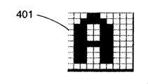
テキストバッファ137は、テキストデータを変換部143へ提供する。次いで、変換部143は、テキストデータのフォントを検出し、テキストデータに対応するフォントマップを辞書141から取得する。この情報を用いて、変換部143は、テキストデータに対応するバイナリピクセルデータを生成する。より詳細には、図4Aおよび4Bに示すように、特定されたフォントの文字「A」のピクセルマップを、バイナリ画像データの列に変換することができる。ピクセルマップ401中のピクセルの各々の列は、画像データのバイナリのライン403に変換され、ここで、それぞれの「空」または「白」のビットが画像データの対応ライン403のバイナリ数「0」に対応し、および、それぞれの「濃」または「暗」が画像データの対応ライン403のバイナリ数「1」に対応する。同様に、画像情報が蓄積され、グラフバッファ139は、変換部143に提供され、バイナリ画像データの列に変換される。図示された本発明の例は、テキストデータまたは画像情報のピクセルの値を示すために1ビットのみを採用しているが、本発明の別の実施形態は、ピクセルの値を示すためにいくつかの数のビットを採用することができることに留意されたい。このように、映写ディスプレー101は、以下で説明するように、グレーまたはカラーで画像を映写することができる。
The
変換された画像データは、ディスプレーバッファ145に格納され、変調部135からの変調信号を制御するために使用することができるまで保持される。前述の通り、変調部135からの変調信号は、レーザダイオード113を駆動する。さらに、変調信号の周波数fmは、一つの走査ラインに沿って表示することのできるピクセル数を決定する。例えば、変調信号の各々の周期が、走査ライン中のピクセルの映写に対応する場合、一つのライン中のピクセルの合計数は、走査ライン方向の振動周波数(図示した実施形態では、X方向振動周波数fxである)の半分である。次いで、ピクセルに対応する変調信号の各々の部分の値は、画像データからの対応するピクセルの値が重畳される。前述の通り、同期制御部133は、ディスプレーバッファ145によって供給される画像データを、変調信号およびX方向振動信号と同期させることで、画像データの列の最初のピクセルが、光映写部103による映写の最初のピクセルに対応する。同様に、同期制御部133は、ディスプレーバッファ145によって提供される画像データをY方向振動信号に同期させることで、画像データの一映写面中の最初のピクセルが、光映写部103による映写面の最初のピクセルの映写に対応する。この方式では、ディスプレーバッファ145からの画像データは、ラスタ表示147のように反射面に映写される。
The converted image data is stored in the
(ペン型映写ディスプレー)
前述した本発明によるペン型ディスプレー101の説明から、そのような映写ディスプレー101を、非常に小型に作ることができることを理解されたい。例えば、ペン型映写上述したようにディスプレー101は、携帯用筆記器具など、ハンドヘルド装置の中に実装する程十分に小さいサイズで製造される。図5を参照して、この図は、例示された実施形態による映写ディスプレーの様々な構成要素が、インク式ペン、グラフィックタブレット用のスタイラスもしくは鉛筆などと、略同様のサイズおよび形状の映写ディスプレー本体501の中に、どのように提供されるかを示す。さらに、映写ディスプレー101に加えて、映写ディスプレー本体501は、筆記手段503を含むこともできる。筆記手段503は、例えば、インク式ペン、グラフィックタブレット用のスタイラスもしくは鉛筆とすることができる。
(Pen-type projection display)
From the above description of the
筆記手段503を有する映写ディスプレー101を提供することによって、映写ディスプレー101は、殆ど全ての状況においてユーザによって、便利に持ち運ばれることができる。ディスプレーバッファ145に格納された画像データを見るために、ユーザは、単純に、映写ディスプレー本体501を反射面から適切な間隔で設置して、映写ディスプレー101を起動する必要がある。このように、本発明による映写ディスプレー101をコンピュータとともに使用することができ、コンピュータが大きなディスプレーを提供する必要がなくなる。
By providing the
上述したように、本発明の様々な実施形態による携帯用映写ディスプレー101において、ディスプレー101によって映写される情報の表示は、ユーザによって手動で制御される。例えば、映写ディスプレー101は、映写ディスプレー101によって映写される画像データの選択のための一つまたは複数の制御ボタンを含むことができる。本発明の実施形態の一部では、ユーザは、コマンドボタンを用いて表示される情報のページを前後にスクロールすることができる。他に、本発明の他の実施形態は、ディスプレー101の位置に基づいて自動的に情報を表示する。例えば、ディスプレー101は、ディスプレー101が、反射面上を移動されたされたときに、情報の逐次スクリーンを映写することもできる。他にまたはさらに、文字が反射面上に印刷されているなど、ディスプレー101がその場所に位置されたときに、ディスプレー101は、特定の場所に対応する情報を表示することができる。本発明のこれらの実施形態のために、ディスプレー101は、例えば、ジャイロ位置検出装置を用いてそれ自体の位置を検出することができる。他に、ディスプレー101は、反射面上の位置表示マークを用いてそれ自体の位置を検出することができる。
As described above, in the
(光源を直接振動させること)
上記の通り、本発明の様々な実施形態は、光源113それ自体または光映写部103全体を直接に振動させることができる。そのような実施形態の一つに採用される光映写部103’は、図6に図示される。この図に見られるように、光映写部103’は、光源113として発光ダイオードを含む。光源113は、基盤601上に配置されている。図示された実施形態では、基盤601は、ガリウム砒素(GaAs)で形成されている。しかし、本発明の別の実施形態では、基盤601は、希望する方向に振動する適切な柔軟性を有するいずれかの種類の基盤とすることができる。
(Vibrating the light source directly)
As described above, various embodiments of the present invention can directly vibrate the
より詳細には、不導体絶縁層603が基盤601の上に形成され、第1の電極605は、絶縁層603の上に形成される。したがって、絶縁層603は、第1の電極605を電気的に、基盤601から絶縁する。次いで、光源113は、光源113の制御電極と電極605との間の電気的接続を形成するために第1の電極605の上に積まれる。次いで、第2の不導体絶縁層607は、第1の電極605の一部の上に形成され、第2の絶縁層609は、第2の電極609は、第2の絶縁層607の上に形成される。したがって、第2の絶縁層607は、第2の電極609を第1の電極605から絶縁する。そして図6に見られるように、光源113の第2の制御電極は、第2の電極と結線611を介して電気的に接続される。
More specifically, the non-conductive insulating
このように、光源113は、変調信号を受信して第1の電極および第2の電極を通じて光源113の動作を制御する。さらに、電極605ならびに609および絶縁層603ならびに607は、比較的に薄いので、基盤601が曲がることを妨げない。したがって、上述の発振器117および119など、発振器は、基盤601および光源113を振動させるために採用されることができる。
Thus, the
前述した光ファイバ115Aを採用する実施形態の意図するところ、光源113または光映写部103を振動させる本発明の実施形態を、携帯用または手のひらサイズの映写ディスプレー101に組み込まれる程度に十分に小さく作ることができる。例えば、図6に示された光映写部103の実施形態では、基盤601を、長さ15mm、幅20μmおよび高さ150μmで実装することができる。この実施形態では、レーザダイオードを、長さ300μm、幅300μmおよび高さ100μmを有する光源113として採用することができる。
The embodiment employing the above-described optical fiber 115A is intended to make the embodiment of the present invention that vibrates the
(結論)
本発明の様々な実施形態を上述したが、これらの実施形態は、模範的なものであって、その実施形態の中では、本発明は、いずれかのコンビネーションまたはサブコンビネーションで、ここで述べられた構成要素およびステップを含む。したがって、本発明を定義するための別のコンビネーションが任意の数だけ存在し、それらコンビネーションは、詳細な説明、特許請求の範囲、図面を含む、明細書から、様々なコンビネーションまたはサブコンビネーションで、一つまたは複数の要素を取り込んだものである。
(Conclusion)
Although various embodiments of the present invention have been described above, these embodiments are exemplary, in which the invention is described herein in any combination or sub-combination. Components and steps. Accordingly, there are any number of other combinations for defining the present invention, such as combinations, sub-combinations from the description, including the detailed description, the claims, and the drawings. It incorporates one or more elements.
例えば、上述の映写ディスプレー101について説明した実施形態は、1色で画像を映写する一方で、本発明の別の実施形態は、複数色で画像を映写することができる。映写ディスプレー101は、例えば、三つの個別の光映写部103を採用することができ、赤、緑および青など、補足的な原色の各々である。各々の光映写部103の光ファイバ115Aを、一つのユニットとして一緒に振動することができる。したがって、各々の光ファイバ115Aは、その色を一つのピクセルに同時に映写する。光映写部103の各々の作用をカラー画像データについての対応に基づいて変更することによって、光映写部103のコンビネーションは、色のついたピクセルを映写し、これによって色のついた画像が映写される。さらに、一つの発振器105を、光映写部103のそれぞれから映写される光を同時に振動するために、採用することができる。さらに、手のひらサイズの実施形態のために、映写ディスプレー101は、1または複数の振動防止装置を含むことができ、これらは、X方向およびY方向の歪みの値を制御して、映写される画像を一つの場所に保つ。
For example, while the embodiment described above for the
当業者にとって、単独であるかコンビネーションであるかにかかわらず、ここに定義された一つまたは複数の機能もしくはステップを用いた、本発明の側面におけるさらなる別のコンビネーションが、本発明の改良および改造としてあるいは本発明の一部分として有用であることは、明らかである。ここに含まれる発明について記載した説明は、そのような変更および改造の全てにわたることを意図されている。例えば、様々な実施形態において、一定のデータの配列が示されている。しかし、データの再配列のいずれもが、本発明によって包含されている。また、サイズ(例えば、バイトまたはビット)といった一定のプロパティの単位が使用されるところでは、他の単位のいずれもが包含されている。 For those skilled in the art, further combinations in aspects of the invention using one or more functions or steps defined herein, whether alone or in combination, are improvements and modifications of the invention. Obviously, it is useful as a part of the present invention. The description of the invention contained herein is intended to cover all such changes and modifications. For example, in various embodiments, an arrangement of certain data is shown. However, any rearrangement of data is encompassed by the present invention. Also, where a unit of a certain property such as size (eg, byte or bit) is used, any other unit is included.
101 映写ディスプレー
103 光映写部
105 発振部
107 周波数生成・変調部
109 画像データ入力部
111 制御部
113 レーザダイオード
115 光ファイバおよびレンズ
117 X方向振動部
119 Y方向振動部
121 波形発生器
123 波形発生器
125 周波数f発生器
127 変調周波数fm発生器
129 周波数fx生成器
131 周波数fy生成器
133 同期制御部
135 変調部
137 テキストバッファ
139 グラフバッファ
141 辞書
143 変換部
145 ディスプレーバッファ
147 ラスタ表示
DESCRIPTION OF
Claims (64)
該光映写部から映写される光を変調する変調部と、
前記光映写部から映写される光を複数の方向へ振動させる発振部と
を備え、
前記発信部は、前記光映写部を第1の方向および前記第1の方向に直交する第2の方向に動かすことを特徴とするペン型映写ディスプレー。 An optical projection unit including a light source and a light transmission device having an optical fiber having a length of about 4 millimeters or 12 millimeters;
A modulation unit that modulates light projected from the projection unit;
An oscillation unit that vibrates light projected from the projection unit in a plurality of directions, and
The pen-shaped projection display characterized in that the transmitting unit moves the optical projection unit in a first direction and a second direction orthogonal to the first direction.
前記光映写部をX方向に振動させる第1の振動部と、
前記光映写部をY方向に振動させる第2の振動部と
を含むことを特徴とする請求項1に記載のペン型映写ディスプレー。 The oscillation unit is
A first vibrating section that vibrates the optical projection section in the X direction;
The pen-type projection display according to claim 1, further comprising: a second vibrating unit that vibrates the optical projection unit in the Y direction.
前記光映写部を軸について回転させる回転装置と、
前記光映写部を前記軸と遠近方向に振動させる振動部と
を含むことを特徴とする請求項1に記載のペン型映写ディスプレー。 The transmitter is
A rotating device that rotates the projection part about an axis;
The pen-type projection display according to claim 1, further comprising: a vibrating unit that vibrates the optical projection unit in the perspective direction.
該光映写部から映写される光を変調する変調部と、
前記光映写部から映写される光を複数の方向へ振動させる発振部であって、前記光映写部を第1の方向および前記第1の方向に直交する第2の方向に動かす、約4.5kHzから5kHzの周波数で前記光映写部をX方向に振動させる第1の振動部および前記光映写部をY方向に振動させる第2の振動部を含む発振部と
を備えたことを特徴とするペン型映写ディスプレー。 The projection section,
A modulation unit that modulates light projected from the projection unit;
3. An oscillation unit that vibrates light projected from the projection unit in a plurality of directions, and moves the projection unit in a first direction and a second direction orthogonal to the first direction. An oscillation unit including a first vibration unit that vibrates the optical projection unit in the X direction at a frequency of 5 kHz to 5 kHz, and a second vibration unit that vibrates the optical projection unit in the Y direction. Pen-type projection display.
該光映写部から映写される光を変調する変調部と、
前記光映写部から映写される光を複数の方向へ振動させる発振部と
を備え、
前記発信部は、前記光映写部を軸について回転させる回転装置および前記光映写部を前記軸と遠近方向に振動させる振動部を含み、前記光映写部を第1の方向および前記第1の方向に直交する第2の方向に動かすことを特徴とするペン型映写ディスプレー。 The projection section,
A modulation unit that modulates light projected from the projection unit;
An oscillation unit that vibrates light projected from the projection unit in a plurality of directions, and
The transmitting unit includes a rotating device that rotates the optical projection unit about an axis, and a vibration unit that vibrates the optical projection unit in a perspective direction with respect to the axis, and the optical projection unit has a first direction and a first direction. A pen-type projection display characterized by moving in a second direction orthogonal to the.
該光映写部から映写される光を変調する変調部と、
前記光映写部から映写される光を複数の方向へ振動させる発振部であって、前記光映写部を第1の方向および前記第1の方向に直交する第2の方向に動かす発信部と、
前記光映写部の近傍に配置される筆記手段と
を備えたことを特徴とする映写ディスプレー。 The projection section,
A modulation unit that modulates light projected from the projection unit;
An oscillation unit that vibrates light projected from the optical projection unit in a plurality of directions, the transmission unit moving the optical projection unit in a first direction and a second direction orthogonal to the first direction;
A projection display comprising: writing means arranged in the vicinity of the projection section.
前記光映写部を軸について回転させる回転装置と、
前記光映写部を前記軸と遠近方向に振動させる振動部と
を含むことを特徴とする請求項11に記載の映写ディスプレー。 The transmitter is
A rotating device that rotates the projection part about an axis;
The projection display according to claim 11, further comprising: a vibrating unit that vibrates the optical projection unit in the near direction.
該光映写部から映写される光を変調する変調部と、
前記光映写部から映写される光を複数の方向へ振動させる発振部であって、前記光映写部をX方向に振動させる第1の振動部および前記光映写部をY方向に振動させる第2の振動部を含み、前記光映写部を第1の方向および前記第1の方向に直交する第2の方向に動かす発信部と、
前記光映写部の近傍に配置される筆記手段と
を備えたことを特徴とする映写ディスプレー。 An optical projection unit including a light source and a light transmission device;
A modulation unit that modulates light projected from the projection unit;
An oscillation unit that vibrates light projected from the projection unit in a plurality of directions, a first oscillation unit that vibrates the projection unit in the X direction and a second that vibrates the projection unit in the Y direction. A transmitting unit that moves the optical projection unit in a first direction and a second direction orthogonal to the first direction;
A projection display comprising: writing means arranged in the vicinity of the projection section.
前記第1の振動部は、前記光映写部を4.5kHzから5kHzの周波数で振動させ、
前記第2の振動部は、前記光映写部を約80Hzの周波数で振動させる
ことを特徴とする請求項19に記載の映写ディスプレー。 The light transmission device is an optical fiber having a length of about 4 millimeters or 12 millimeters;
The first vibration unit vibrates the optical projection unit at a frequency of 4.5 kHz to 5 kHz,
The projection display according to claim 19, wherein the second vibration unit vibrates the optical projection unit at a frequency of about 80 Hz.
前記第1の光映写部から映写される光を変調する第1の変調部と、
第2の光源および約4ミリメートルから12ミリメートルの長さの第2の光ファイバを有する第2の光伝達装置を含む、第2の色の光を映写する第2の光映写部と、
前記第2の光映写部から映写される光を変調する第2の変調部と、
前記第1の光映写部および前記第2の光映写部から映写される前記光を第1の方向および第1の方向に直交する第2の方向に動かすための少なくとも一つの発振部と
を備えたことを特徴とする映写ディスプレー。 A first light projection portion for projecting light of a first color, comprising a first light transmission device having a first light source and a first optical fiber having a length of about 4 to 12 millimeters;
A first modulation unit for modulating light projected from the first optical projection unit;
A second light projection portion for projecting light of the second color, including a second light transmission device having a second light source and a second optical fiber having a length of about 4 to 12 millimeters;
A second modulation unit for modulating light projected from the second optical projection unit;
At least one oscillating unit for moving the light projected from the first optical projection unit and the second optical projection unit in a first direction and a second direction orthogonal to the first direction. Projection display characterized by that.
前記第1の光映写部および前記第2の光映写部の双光映写部をX方向に振動する第1の振動部と、
前記第1の光映写部および前記第2の光映写部の双光映写部をY方向に振動する第2の振動部と
を含むことを特徴とする請求項27に記載の映写ディスプレー。 The at least one oscillator is
A first vibrating section that vibrates in the X direction the two-light projected section of the first projected section and the second projected section;
28. The projection display according to claim 27, further comprising: a second vibrating section that vibrates a dual-light projection section of the first projection section and the second projection section in the Y direction.
前記第1の光映写部から映写される前記光を複数の方向に動かす第1の発信部と、
前記第2の光映写部から映写される前記光を複数の方向に動かす第2の発振部と
を含むことを特徴とする請求項27に記載の映写ディスプレー。 The at least one oscillator is
A first transmitter that moves the light projected from the first projector in a plurality of directions;
28. The projection display according to claim 27, further comprising: a second oscillation unit that moves the light projected from the second projection unit in a plurality of directions.
前記第1の光映写部および前記第2の光映写部を軸について回転させる回転装置と、
前記第1の光映写部および前記第2の光映写部の双光映写部を前記軸と遠近方向に振動させる振動部と
を含むことを特徴とする請求項27に記載の映写ディスプレー。 The at least one oscillator is
A rotating device for rotating the first optical projection unit and the second optical projection unit about an axis;
28. The projection display according to claim 27, further comprising: a vibration unit that vibrates the first optical projection unit and the dual optical projection unit of the second optical projection unit in the axis and the perspective direction.
前記第1の光映写部をX方向に振動させる第1の振動部と、
前記第1の光映写部をY方向に振動させる第2の振動部と
を含み、
前記第2の発信部は、
前記第2の光映写部をX方向に振動させる第3の振動部と、
前記第2の光映写部をY方向に振動させる第4の振動部と
を含むことを特徴とする請求項29に記載の映写ディスプレー。 The first oscillation unit includes:
A first vibrating section that vibrates the first optical projection section in the X direction;
A second vibrating part that vibrates the first optical projection part in the Y direction,
The second transmitter is
A third vibrating section that vibrates the second optical projection section in the X direction;
30. The projection display according to claim 29, further comprising: a fourth vibrating section that vibrates the second optical projection section in the Y direction.
前記第1の光映写部を第1の軸について回転させる第1の回転装置と、
前記第1の光映写部を前記第1の軸と遠近方向に振動させる第1の振動部と
を含み、
前記第2の発信部は、
前記第2の光映写部を第2の軸について回転させる第2の回転装置と、
前記第2の光映写部を前記第2の軸と遠近方向に振動させる第2の振動部と
を含むことを特徴とする請求項29に記載の映写ディスプレー。 The first oscillation unit includes:
A first rotating device for rotating the first optical projection unit about a first axis;
A first vibrating part that vibrates the first optical projection part in the perspective direction with the first axis;
The second transmitter is
A second rotating device for rotating the second optical projection unit about a second axis;
30. The projection display according to claim 29, further comprising: a second vibrating section that vibrates the second optical projection section in the perspective direction with respect to the second axis.
前記第1の光映写部から映写される光を変調する第1の変調部と、
第2の色の光を映写する第2の光映写部と、
前記第2の光映写部から映写される光を変調する第2の変調部と、
前記第1の光映写部および前記第2の光映写部から映写される前記光を第1の方向および第1の方向に直交する第2の方向に動かすための少なくとも一つの発振部と
を備え、
前記少なくとも一つの発振部は、
前記第1の光映写部および前記第2の光映写部を軸について回転させる回転装置と、
前記第1の光映写部および前記第2の光映写部の双光映写部を前記軸と遠近方向に振動させる振動部と
を含むことを特徴とする映写ディスプレー。 A first optical projection unit for projecting light of the first color;
A first modulation unit for modulating light projected from the first optical projection unit;
A second light projection unit for projecting light of the second color;
A second modulation unit for modulating light projected from the second optical projection unit;
At least one oscillating unit for moving the light projected from the first optical projection unit and the second optical projection unit in a first direction and a second direction orthogonal to the first direction. ,
The at least one oscillator is
A rotating device for rotating the first optical projection unit and the second optical projection unit about an axis;
A projection display, comprising: a vibrating section that vibrates the first and second projection sections of the first projection section and the second projection section in the perspective direction.
前記第1の光映写部から映写される光を変調する第1の変調部と、
第2の色の光を映写する第2の光映写部と、
前記第2の光映写部から映写される光を変調する第2の変調部と、
前記第1の光映写部および前記第2の光映写部から映写される前記光を第1の方向および第1の方向に直交する第2の方向に動かすための少なくとも一つの発振部と
を備え、
前記少なくとも一つの発振部は、
前記第1の光映写部をX方向に振動させる第1の振動部と、
前記第1の光映写部をY方向に振動させる第2の振動部と
を含む、前記第1の光映写部から映写される前記光を複数の方向に動かす第1の発振部と、
前記第2の光映写部をX方向に振動させる第3の振動部と、
前記第2の光映写部をY方向に振動させる第4の振動部と
を含む、前記第2の光映写部から映写される前記光を複数の方向に動かす第2の発信部と
を含むことを特徴とするペン型映写ディスプレー。 A first optical projection unit for projecting light of the first color;
A first modulation unit for modulating light projected from the first optical projection unit;
A second light projection unit for projecting light of the second color;
A second modulation unit for modulating light projected from the second optical projection unit;
At least one oscillating unit for moving the light projected from the first optical projection unit and the second optical projection unit in a first direction and a second direction orthogonal to the first direction. ,
The at least one oscillator is
A first vibrating section that vibrates the first optical projection section in the X direction;
A first oscillating unit that moves the light projected from the first optical projection unit in a plurality of directions, and a second oscillation unit that vibrates the first optical projection unit in the Y direction;
A third vibrating section that vibrates the second optical projection section in the X direction;
A second transmitting unit that moves the light projected from the second optical projection unit in a plurality of directions, and a fourth oscillation unit that vibrates the second optical projection unit in the Y direction. Pen-type projection display featuring
前記第1の光映写部から映写される光を変調する第1の変調部と、
第2の色の光を映写する第2の光映写部と、
前記第2の光映写部から映写される光を変調する第2の変調部と、
前記第1の光映写部および前記第2の光映写部から映写される前記光を第1の方向および第1の方向に直交する第2の方向に動かすための少なくとも一つの発振部と
を備え、
前記少なくとも一つの発振部は、
前記第1の光映写部を第1の軸について回転させる第1の回転装置と、
前記第1の光映写部を前記第1の軸と遠近方向に振動させる第1の振動部と
を含む、前記第1の光映写部から映写される前記光を複数の方向に動かす第1の発振部と、
前記第2の光映写部を第2の軸について回転させる第2の回転装置と、
前記第2の光映写部を前記第2の軸と遠近方向に振動させる第2の振動部と
を含む、前記第2の光映写部から映写される前記光を複数の方向に動かす第2の発信部と
を含むことを特徴とする映写ディスプレー。 A first optical projection unit for projecting light of the first color;
A first modulation unit for modulating light projected from the first optical projection unit;
A second light projection unit for projecting light of the second color;
A second modulation unit for modulating light projected from the second optical projection unit;
At least one oscillating unit for moving the light projected from the first optical projection unit and the second optical projection unit in a first direction and a second direction orthogonal to the first direction. ,
The at least one oscillator is
A first rotating device for rotating the first optical projection unit about a first axis;
A first vibrating unit that vibrates the first optical projection unit in the perspective direction with the first axis, and moves the light projected from the first optical projection unit in a plurality of directions. An oscillation unit;
A second rotating device for rotating the second optical projection unit about a second axis;
A second vibrating unit that vibrates the second optical projection unit in the perspective direction with the second axis, and moves the light projected from the second optical projection unit in a plurality of directions. A projection display characterized by including a transmitter.
前記第1の光映写部から映写される光を変調する第1の変調部と、
第2の色の光を映写する第2の光映写部と、
前記第2の光映写部から映写される光を変調する第2の変調部と、
前記第1の光映写部および前記第2の光映写部から映写される前記光を第1の方向および第1の方向に直交する第2の方向に動かすための少なくとも一つの発振部と、
前記第1の光映写部および前記第2の光映写部の双光映写部の近傍に配置される筆記手段を備えたことを特徴とする映写ディスプレー。 A first optical projection unit for projecting light of the first color;
A first modulation unit for modulating light projected from the first optical projection unit;
A second light projection unit for projecting light of the second color;
A second modulation unit for modulating light projected from the second optical projection unit;
At least one oscillation unit for moving the light projected from the first optical projection unit and the second optical projection unit in a first direction and a second direction orthogonal to the first direction;
A projection display comprising writing means arranged in the vicinity of a dual projection section of the first projection section and the second projection section.
前記第2の光映写部は、第2の光源および第2の光伝達装置を含む
ことを特徴とする請求項34に記載のペン型映写ディスプレー。 The first optical projection unit includes a first light source and a first light transmission device,
The pen-type projection display according to claim 34 , wherein the second optical projection unit includes a second light source and a second optical transmission device.
前記第1の光映写部および前記第2の光映写部の双光映写部をX方向に振動させる第1の振動部と、
前記第1の光映写部および前記第2の光映写部の双光映写部をY方向に振動させる第2の振動部と
を含むことを特徴とする請求項36に記載の映写ディスプレー。 The at least one oscillator is
A first vibration unit that vibrates a dual-light projection unit of the first optical projection unit and the second optical projection unit in the X direction;
37. The projection display according to claim 36, further comprising: a second vibration unit that vibrates a dual-light projection unit of the first optical projection unit and the second optical projection unit in the Y direction.
前記第1の光映写部から映写される前記光を複数の方向へ動かす第1の発振部と、
前記第2の光映写部から映写される前記光を複数の方向へ動かす第2の発振部と
を含む
ことを特徴とする請求項36に記載の映写ディスプレー。 The at least one oscillator is
A first oscillation unit that moves the light projected from the first optical projection unit in a plurality of directions;
37. The projection display according to claim 36, further comprising: a second oscillation unit that moves the light projected from the second projection unit in a plurality of directions.
前記第1の光映写部をX方向に振動させる第1の振動部と、
前記第1の光映写部をY方向に振動させる第2の振動部と
を含み、
前記第2の発振部は、
前記第2の光映写部をX方向に振動させる第3の振動部と、
前記第2の光映写部をY方向に振動させる第4の振動部と
を含むことを特徴とする請求項41に記載の映写ディスプレー。 The first oscillation unit includes:
A first vibrating section that vibrates the first optical projection section in the X direction;
A second vibrating part that vibrates the first optical projection part in the Y direction,
The second oscillation unit includes:
A third vibrating section that vibrates the second optical projection section in the X direction;
42. The projection display according to claim 41, further comprising: a fourth vibrating unit that vibrates the second optical projection unit in the Y direction.
前記第1の光映写部を第1の軸について回転させる第1の回転装置と、
前記第1の光映写部を前記第1の軸と遠近方向に振動させる第1の振動部と
を含み、
前記第2の発信部は、
前記第2の光映写部を第2の軸について回転させる第2の回転装置と、
前記第2の光映写部を前記第2の軸と遠近方向に振動させる第2の振動部と
を含むことを特徴とする請求項36に記載の映写ディスプレー。 The first oscillation unit includes:
A first rotating device for rotating the first optical projection unit about a first axis;
A first vibrating part that vibrates the first optical projection part in the perspective direction with the first axis;
The second transmitter is
A second rotating device for rotating the second optical projection unit about a second axis;
37. The projection display according to claim 36, further comprising: a second vibration unit that vibrates the second optical projection unit in the perspective direction with respect to the second axis.
前記第1の光映写部から映写される光を変調する第1の変調部と、
第2の光源および第2の光伝達装置を含む、第2の色の光を映写する第2の光映写部と、
前記第2の光映写部から映写される光を変調する第2の変調部と、
前記第1の光映写部をX方向に振動させる第1の振動部および前記第1の光映写部をY方向に振動させる第2の振動部を含み、前記第1の光映写部から映写される前記光を複数の方向に動かす第1の発信部と、
前記第2の光映写部をX方向に振動させる第3の振動部および前記第2の光映写部をY方向に振動させる第4の振動部を含み、前記第2の光映写部から映写される前記光を複数の方向に動かす第2の発振部と
を備えたことを特徴とするペン型映写ディスプレー。 A first light projection unit for projecting light of the first color, including a first light source and a first light transmission device;
A first modulation unit for modulating light projected from the first optical projection unit;
A second light projection unit for projecting light of the second color, including a second light source and a second light transmission device;
A second modulation unit for modulating light projected from the second optical projection unit;
The first optical projection unit includes a first vibration unit that vibrates in the X direction and a second vibration unit that vibrates the first optical projection unit in the Y direction, and is projected from the first optical projection unit. A first transmitter that moves the light in a plurality of directions;
A third vibration unit that vibrates the second optical projection unit in the X direction; and a fourth vibration unit that vibrates the second optical projection unit in the Y direction, and is projected from the second optical projection unit. A pen-type projection display, comprising: a second oscillation unit that moves the light in a plurality of directions.
前記第1の光映写部から映写される光を変調する第1の変調部と、
第2の光源および第2の光伝達装置を含む、第2の色の光を映写する第2の光映写部と、
前記第2の光映写部から映写される光を変調する第2の変調部と、
前記第1の光映写部を第1の軸について回転させる第1の回転装置および前記第1の光映写部を前記第1の軸と遠近方向に振動させる第1の振動部を含み、前記第1の光映写部から映写される前記光を複数の方向に動かす第1の発信部と、
前記第2の光映写部を第2の軸について回転させる第2の回転装置および前記第2の光映写部を前記第2の軸と遠近方向に振動させる第2の振動部を含み、前記第2の光映写部から映写される前記光を複数の方向に動かす第2の発振部と
を備えたことを特徴とする映写ディスプレー。 A first light projection unit for projecting light of the first color, including a first light source and a first light transmission device;
A first modulation unit for modulating light projected from the first optical projection unit;
A second light projection unit for projecting light of the second color, including a second light source and a second light transmission device;
A second modulation unit for modulating light projected from the second optical projection unit;
A first rotation device that rotates the first optical projection unit about a first axis; and a first vibration unit that vibrates the first optical projection unit in a perspective direction with respect to the first axis. A first transmitter that moves the light projected from one optical projection unit in a plurality of directions;
A second rotating device that rotates the second optical projection unit about a second axis; and a second vibrating unit that vibrates the second optical projection unit in a perspective direction with respect to the second axis. A projection display comprising: a second oscillation unit that moves the light projected from the two projection units in a plurality of directions.
前記第2の光伝達装置は、第2の光ファイバを含む
ことを特徴とする請求項44に記載のペン型映写ディスプレー。 The first optical transmission device includes a first optical fiber,
The pen-type projection display according to claim 44 , wherein the second light transmission device includes a second optical fiber.
前記第2の光映写部は、第2の光源および第2の光伝達装置を含むThe second optical projection unit includes a second light source and a second light transmission device.
ことを特徴とする請求項33,35または36に記載の映写ディスプレー。37. A projection display according to claim 33, 35 or 36.
前記第2の光伝達装置は、第2の光ファイバを含むThe second optical transmission device includes a second optical fiber.
ことを特徴とする請求項37または45に記載の映写ディスプレー。46. A projection display according to claim 37 or 45.
Applications Claiming Priority (1)
| Application Number | Priority Date | Filing Date | Title |
|---|---|---|---|
| US10/284,470 US7036938B2 (en) | 2002-10-31 | 2002-10-31 | Pen projection display |
Publications (3)
| Publication Number | Publication Date |
|---|---|
| JP2004170927A JP2004170927A (en) | 2004-06-17 |
| JP2004170927A5 JP2004170927A5 (en) | 2006-11-02 |
| JP3929956B2 true JP3929956B2 (en) | 2007-06-13 |
Family
ID=32093525
Family Applications (1)
| Application Number | Title | Priority Date | Filing Date |
|---|---|---|---|
| JP2003338671A Expired - Fee Related JP3929956B2 (en) | 2002-10-31 | 2003-09-29 | Pen-type projection display |
Country Status (6)
| Country | Link |
|---|---|
| US (3) | US7036938B2 (en) |
| EP (1) | EP1416740B1 (en) |
| JP (1) | JP3929956B2 (en) |
| KR (1) | KR100954656B1 (en) |
| CN (1) | CN100468106C (en) |
| BR (1) | BR0304278A (en) |
Families Citing this family (36)
| Publication number | Priority date | Publication date | Assignee | Title |
|---|---|---|---|---|
| US6549935B1 (en) * | 1999-05-25 | 2003-04-15 | Silverbrook Research Pty Ltd | Method of distributing documents having common components to a plurality of destinations |
| EP1302891A1 (en) * | 2001-10-12 | 2003-04-16 | Siemens Aktiengesellschaft | Apparatus for the detection and display of motion |
| US7133563B2 (en) | 2002-10-31 | 2006-11-07 | Microsoft Corporation | Passive embedded interaction code |
| US20080048979A1 (en) * | 2003-07-09 | 2008-02-28 | Xolan Enterprises Inc. | Optical Method and Device for use in Communication |
| US20050264525A1 (en) * | 2004-05-27 | 2005-12-01 | Adams Charles R | Mouse pointing system/icon identification system |
| US7505982B2 (en) * | 2004-12-03 | 2009-03-17 | Microsoft Corporation | Local metadata embedding solution |
| JP4672023B2 (en) * | 2004-12-23 | 2011-04-20 | ユニバーシティ・オブ・ワシントン | Method for driving a scanning beam device to achieve a high frame rate |
| US7536051B2 (en) * | 2005-02-17 | 2009-05-19 | Microsoft Corporation | Digital pen calibration by local linearization |
| US7607076B2 (en) * | 2005-02-18 | 2009-10-20 | Microsoft Corporation | Embedded interaction code document |
| US7826074B1 (en) | 2005-02-25 | 2010-11-02 | Microsoft Corporation | Fast embedded interaction code printing with custom postscript commands |
| US7532366B1 (en) | 2005-02-25 | 2009-05-12 | Microsoft Corporation | Embedded interaction code printing with Microsoft Office documents |
| US7421439B2 (en) * | 2005-04-22 | 2008-09-02 | Microsoft Corporation | Global metadata embedding and decoding |
| US7400777B2 (en) | 2005-05-25 | 2008-07-15 | Microsoft Corporation | Preprocessing for information pattern analysis |
| US7729539B2 (en) | 2005-05-31 | 2010-06-01 | Microsoft Corporation | Fast error-correcting of embedded interaction codes |
| US7619607B2 (en) * | 2005-06-30 | 2009-11-17 | Microsoft Corporation | Embedding a pattern design onto a liquid crystal display |
| US7528848B2 (en) * | 2005-06-30 | 2009-05-05 | Microsoft Corporation | Embedded interaction code decoding for a liquid crystal display |
| US7410260B2 (en) * | 2005-08-04 | 2008-08-12 | Texas Instruments Incorporated | Use of a CCD camera in a projector platform for smart screen capability and other enhancements |
| US7817816B2 (en) | 2005-08-17 | 2010-10-19 | Microsoft Corporation | Embedded interaction code enabled surface type identification |
| KR101424157B1 (en) * | 2005-12-10 | 2014-07-31 | 박순영 | Pen type digital dictionary including Laser projector |
| CN101517455B (en) * | 2006-09-15 | 2012-01-11 | 日本电气株式会社 | Laser projector |
| US8519983B2 (en) * | 2007-12-29 | 2013-08-27 | Microvision, Inc. | Input device for a scanned beam display |
| US20090219262A1 (en) * | 2007-12-29 | 2009-09-03 | Microvision, Inc. | Active Input Device for a Scanned Beam Display |
| AT508519A1 (en) | 2008-10-30 | 2011-02-15 | Isiqiri Interface Tech Gmbh | WRITING DEVICE AND METHOD FOR OPERATING A WRITING DEVICE |
| WO2012109997A1 (en) * | 2011-02-20 | 2012-08-23 | Sunwell Concept Limited | Portable scanner |
| US9354748B2 (en) * | 2012-02-13 | 2016-05-31 | Microsoft Technology Licensing, Llc | Optical stylus interaction |
| US9075566B2 (en) | 2012-03-02 | 2015-07-07 | Microsoft Technoogy Licensing, LLC | Flexible hinge spine |
| US9460029B2 (en) | 2012-03-02 | 2016-10-04 | Microsoft Technology Licensing, Llc | Pressure sensitive keys |
| US20130300590A1 (en) | 2012-05-14 | 2013-11-14 | Paul Henry Dietz | Audio Feedback |
| CN102759797A (en) * | 2012-07-06 | 2012-10-31 | 胡宵 | Writing device |
| US8964379B2 (en) | 2012-08-20 | 2015-02-24 | Microsoft Corporation | Switchable magnetic lock |
| US10151875B2 (en) | 2013-01-15 | 2018-12-11 | Magic Leap, Inc. | Ultra-high resolution scanning fiber display |
| KR102067759B1 (en) | 2013-02-15 | 2020-01-17 | 삼성전자주식회사 | Fiber scanning projector |
| US10324733B2 (en) | 2014-07-30 | 2019-06-18 | Microsoft Technology Licensing, Llc | Shutdown notifications |
| CN111830704B (en) * | 2019-04-23 | 2022-06-17 | 成都理想境界科技有限公司 | Scanning display device, optical fiber scanner and scanning method |
| US11487400B1 (en) * | 2021-08-13 | 2022-11-01 | International Business Machines Corporation | Aggregated multidimensional user interface display with electronic pen for holographic projection |
| EP4234264A1 (en) * | 2022-02-25 | 2023-08-30 | BIC Violex Single Member S.A. | Methods and systems for transforming speech into visual text |
Family Cites Families (26)
| Publication number | Priority date | Publication date | Assignee | Title |
|---|---|---|---|---|
| JPS63165584U (en) * | 1987-04-16 | 1988-10-27 | ||
| DE3826442A1 (en) * | 1988-08-03 | 1990-02-08 | Royocad Ges Fuer Hard Und Soft | PROJECTION HEAD |
| US5032924A (en) * | 1989-04-10 | 1991-07-16 | Nilford Laboratories, Inc. | System for producing an image from a sequence of pixels |
| US5097354A (en) | 1989-07-27 | 1992-03-17 | Omron Corporation | Beam scanner |
| US5003179A (en) * | 1990-05-01 | 1991-03-26 | Hughes Aircraft Company | Full color upconversion display |
| JPH0451011A (en) | 1990-06-18 | 1992-02-19 | Pioneer Electron Corp | Laser light projection type display device |
| JPH06209482A (en) * | 1993-01-11 | 1994-07-26 | Nippon Telegr & Teleph Corp <Ntt> | Picture reproduction device |
| US6655597B1 (en) * | 2000-06-27 | 2003-12-02 | Symbol Technologies, Inc. | Portable instrument for electro-optically reading indicia and for projecting a bit-mapped color image |
| US6832724B2 (en) * | 1993-03-26 | 2004-12-21 | Symbol Technologies, Inc. | Electro-optical assembly for image projection, especially in portable instruments |
| US5398082A (en) * | 1993-05-20 | 1995-03-14 | Hughes-Jvc Technology Corporation | Scanned illumination for light valve video projectors |
| JPH0720812A (en) * | 1993-07-02 | 1995-01-24 | Sega Enterp Ltd | Polar coordinate scanning system spherical projecting device |
| US5673139A (en) | 1993-07-19 | 1997-09-30 | Medcom, Inc. | Microelectromechanical television scanning device and method for making the same |
| US5335150A (en) | 1993-08-31 | 1994-08-02 | Huang Chao C | Laser pointer with a constant power output control |
| JPH07225564A (en) * | 1994-02-15 | 1995-08-22 | Sony Corp | Direct view type laser tube |
| US5727098A (en) | 1994-09-07 | 1998-03-10 | Jacobson; Joseph M. | Oscillating fiber optic display and imager |
| US6254253B1 (en) | 1998-01-22 | 2001-07-03 | Viewpoint Technology, Inc. | Deflectable laser source having movable piezu elements for projecting images |
| US6584052B1 (en) * | 1998-06-02 | 2003-06-24 | Science Applications International Corporation | Method and apparatus for controlling the focus of a read/write head for an optical scanner |
| JP2000131640A (en) * | 1998-10-23 | 2000-05-12 | Sony Corp | Picture display device |
| DE19851000C2 (en) * | 1998-11-05 | 2001-07-26 | Dornier Gmbh | Projection arrangement |
| US6294775B1 (en) | 1999-06-08 | 2001-09-25 | University Of Washington | Miniature image acquistion system using a scanning resonant waveguide |
| TW472993U (en) | 2000-06-08 | 2002-01-11 | Microtek Int Inc | Scanner light board capable of previewing transparent document |
| US6585154B1 (en) * | 2000-08-03 | 2003-07-01 | Yaakov Ostrover | System, method and devices for documents with electronic copies attached thereto |
| US7102700B1 (en) * | 2000-09-02 | 2006-09-05 | Magic Lantern Llc | Laser projection system |
| US6856712B2 (en) | 2000-11-27 | 2005-02-15 | University Of Washington | Micro-fabricated optical waveguide for use in scanning fiber displays and scanned fiber image acquisition |
| US6811091B2 (en) * | 2000-12-29 | 2004-11-02 | Siemens Automotive Corporation | Modular fuel injector having an integral filter and dynamic adjustment assembly |
| KR100408518B1 (en) * | 2001-04-12 | 2003-12-06 | 삼성전자주식회사 | Pen input device and Measuring method of coordinate |
-
2002
- 2002-10-31 US US10/284,470 patent/US7036938B2/en not_active Expired - Fee Related
-
2003
- 2003-09-26 EP EP03021852A patent/EP1416740B1/en not_active Expired - Lifetime
- 2003-09-29 BR BR0304278-2A patent/BR0304278A/en not_active IP Right Cessation
- 2003-09-29 KR KR1020030067505A patent/KR100954656B1/en not_active IP Right Cessation
- 2003-09-29 JP JP2003338671A patent/JP3929956B2/en not_active Expired - Fee Related
- 2003-09-30 CN CNB031434827A patent/CN100468106C/en not_active Expired - Fee Related
-
2004
- 2004-05-20 US US10/849,249 patent/US20040212553A1/en not_active Abandoned
- 2004-11-23 US US10/997,726 patent/US6964483B2/en not_active Expired - Fee Related
Also Published As
| Publication number | Publication date |
|---|---|
| EP1416740A3 (en) | 2004-07-14 |
| JP2004170927A (en) | 2004-06-17 |
| US20040085523A1 (en) | 2004-05-06 |
| CN100468106C (en) | 2009-03-11 |
| US20040212553A1 (en) | 2004-10-28 |
| BR0304278A (en) | 2004-08-31 |
| KR20040038647A (en) | 2004-05-08 |
| EP1416740B1 (en) | 2012-08-15 |
| EP1416740A2 (en) | 2004-05-06 |
| US7036938B2 (en) | 2006-05-02 |
| CN1499427A (en) | 2004-05-26 |
| US6964483B2 (en) | 2005-11-15 |
| KR100954656B1 (en) | 2010-04-27 |
| US20050073657A1 (en) | 2005-04-07 |
Similar Documents
| Publication | Publication Date | Title |
|---|---|---|
| JP3929956B2 (en) | Pen-type projection display | |
| US11252385B2 (en) | Scanning laser projection display for small handheld devices | |
| US4953971A (en) | Interactive image projection apparatus | |
| US6800844B2 (en) | Two-dimensional optical scanner and method of driving the same | |
| EP1444639B1 (en) | Electro-optical assembly for image projection, especially in portable instruments | |
| US7287862B2 (en) | Compact image projection module | |
| JP2935290B2 (en) | Display device using flat display panel | |
| JP2004170927A5 (en) | ||
| US9441822B2 (en) | Color optical pen for electronic panel | |
| US20040070563A1 (en) | Wearable imaging device | |
| KR100488461B1 (en) | Laser display device | |
| JP2008089931A (en) | Image display device and method of varying image size | |
| JP2019061197A (en) | Video device | |
| JP2000284222A (en) | Laser pointer and laser pointer system | |
| JP2001290603A (en) | Coordinate input/detection device and electronic blackboard system | |
| JP2002297089A (en) | Display device and input system | |
| JPH10207394A (en) | Head mounted display system | |
| JPH0820854B2 (en) | Small display device | |
| JPH05158416A (en) | Display device | |
| JPH11305690A (en) | Picture display device and picture plotting device | |
| KR20040092323A (en) | Wireless mouse using as a pointer | |
| JPH11295630A (en) | Picture display device and picture forming device | |
| JPH06178236A (en) | Small sized display device | |
| JPH01228262A (en) | Image input/output device | |
| ITTO20010668A1 (en) | PERSONAL VISUALIZATION SYSTEM. |
Legal Events
| Date | Code | Title | Description |
|---|---|---|---|
| A521 | Request for written amendment filed |
Free format text: JAPANESE INTERMEDIATE CODE: A523 Effective date: 20060912 |
|
| A621 | Written request for application examination |
Free format text: JAPANESE INTERMEDIATE CODE: A621 Effective date: 20060912 |
|
| A871 | Explanation of circumstances concerning accelerated examination |
Free format text: JAPANESE INTERMEDIATE CODE: A871 Effective date: 20060912 |
|
| A975 | Report on accelerated examination |
Free format text: JAPANESE INTERMEDIATE CODE: A971005 Effective date: 20061005 |
|
| A131 | Notification of reasons for refusal |
Free format text: JAPANESE INTERMEDIATE CODE: A131 Effective date: 20061020 |
|
| A521 | Request for written amendment filed |
Free format text: JAPANESE INTERMEDIATE CODE: A523 Effective date: 20070122 |
|
| TRDD | Decision of grant or rejection written | ||
| A01 | Written decision to grant a patent or to grant a registration (utility model) |
Free format text: JAPANESE INTERMEDIATE CODE: A01 Effective date: 20070227 |
|
| A61 | First payment of annual fees (during grant procedure) |
Free format text: JAPANESE INTERMEDIATE CODE: A61 Effective date: 20070307 |
|
| R150 | Certificate of patent or registration of utility model |
Free format text: JAPANESE INTERMEDIATE CODE: R150 |
|
| FPAY | Renewal fee payment (event date is renewal date of database) |
Free format text: PAYMENT UNTIL: 20110316 Year of fee payment: 4 |
|
| FPAY | Renewal fee payment (event date is renewal date of database) |
Free format text: PAYMENT UNTIL: 20110316 Year of fee payment: 4 |
|
| FPAY | Renewal fee payment (event date is renewal date of database) |
Free format text: PAYMENT UNTIL: 20120316 Year of fee payment: 5 |
|
| FPAY | Renewal fee payment (event date is renewal date of database) |
Free format text: PAYMENT UNTIL: 20130316 Year of fee payment: 6 |
|
| FPAY | Renewal fee payment (event date is renewal date of database) |
Free format text: PAYMENT UNTIL: 20140316 Year of fee payment: 7 |
|
| LAPS | Cancellation because of no payment of annual fees |