JP3926366B2 - Spread spectrum rake receiver - Google Patents
Spread spectrum rake receiver Download PDFInfo
- Publication number
- JP3926366B2 JP3926366B2 JP2004535849A JP2004535849A JP3926366B2 JP 3926366 B2 JP3926366 B2 JP 3926366B2 JP 2004535849 A JP2004535849 A JP 2004535849A JP 2004535849 A JP2004535849 A JP 2004535849A JP 3926366 B2 JP3926366 B2 JP 3926366B2
- Authority
- JP
- Japan
- Prior art keywords
- timing
- interference
- signal
- mics
- path
- Prior art date
- Legal status (The legal status is an assumption and is not a legal conclusion. Google has not performed a legal analysis and makes no representation as to the accuracy of the status listed.)
- Expired - Fee Related
Links
Images


Classifications
-
- H—ELECTRICITY
- H04—ELECTRIC COMMUNICATION TECHNIQUE
- H04B—TRANSMISSION
- H04B1/00—Details of transmission systems, not covered by a single one of groups H04B3/00 - H04B13/00; Details of transmission systems not characterised by the medium used for transmission
- H04B1/69—Spread spectrum techniques
- H04B1/707—Spread spectrum techniques using direct sequence modulation
- H04B1/7097—Interference-related aspects
- H04B1/711—Interference-related aspects the interference being multi-path interference
- H04B1/7115—Constructive combining of multi-path signals, i.e. RAKE receivers
-
- H—ELECTRICITY
- H04—ELECTRIC COMMUNICATION TECHNIQUE
- H04B—TRANSMISSION
- H04B1/00—Details of transmission systems, not covered by a single one of groups H04B3/00 - H04B13/00; Details of transmission systems not characterised by the medium used for transmission
- H04B1/69—Spread spectrum techniques
- H04B1/707—Spread spectrum techniques using direct sequence modulation
- H04B1/7097—Interference-related aspects
- H04B1/7103—Interference-related aspects the interference being multiple access interference
- H04B1/7107—Subtractive interference cancellation
-
- H—ELECTRICITY
- H04—ELECTRIC COMMUNICATION TECHNIQUE
- H04B—TRANSMISSION
- H04B1/00—Details of transmission systems, not covered by a single one of groups H04B3/00 - H04B13/00; Details of transmission systems not characterised by the medium used for transmission
- H04B1/69—Spread spectrum techniques
- H04B1/707—Spread spectrum techniques using direct sequence modulation
- H04B1/7097—Interference-related aspects
- H04B1/711—Interference-related aspects the interference being multi-path interference
- H04B1/7115—Constructive combining of multi-path signals, i.e. RAKE receivers
- H04B1/712—Weighting of fingers for combining, e.g. amplitude control or phase rotation using an inner loop
Description
発明の背景Background of the Invention
本発明はスペクトラム拡散方式に係り、更に詳しくはマルチパス環境での受信ダイバーシティ方式として、伝搬路の多重反射により様々な遅延時間差を有してアンテナに到来する信号の時間領域での最大比合成を行うレイク受信機に関する。 The present invention relates to a spread spectrum system, and more specifically, as a reception diversity system in a multipath environment, a maximum ratio synthesis in a time domain of a signal arriving at an antenna having various delay time differences due to multiple reflection of a propagation path. The rake receiver to perform.
スペクトラム拡散、またはスペクトル拡散通信方式は移動体通信の最も基本的な技術として広範囲に利用されている。スペクトラム拡散通信の最も単純なモデルとしての直接拡散(DS)方式では送るべき情報信号の周期Tに対して、その1/100から1/1000程度のチップ幅Tcを持つPN信号を拡散信号として変調、すなわち乗算してスペクトルを広げて受信側に送信する。
受信側では雑音に埋もれた信号から、逆拡散によって信号成分を検出する。逆拡散とは、基本的に受信信号中のPN信号と同じ位相の同一PN信号を受信信号に乗じて、復調を行うことである。
しかしながら直接波の他に多くの反射波が存在するようなマルチパス環境においては、様々な遅延時間差をもって受信される信号を適切に合成することによって、正しい信号成分を検出する必要がある。
このような従来技術の1つとして、レイク(Rake)方式がある。レイクとは英語“でくまで”の意味であり、レイク方式は“くまで”のように伝送路の遅延分散により分散した信号パワーを1つに集めて最大比合成を行うダイバーシティ方式である。
従来のレイク受信機では、既知の信号を用いてマルチパスが到着する複数のパスタイミングを見つけ、このタイミングを復調器に知らせて、復調器ではこのタイミングで逆拡散を行い、マルチパスの信号を合成することにより、希望信号を復調している。
図1は、例えば移動通信端末としてのレイク受信機の全体構成例を示すブロック図である。同図において受信機はアンテナ100、無線受信部101、A/D変換部102、複数のマルチパスのタイミングを検出するサーチャ103、サーチャ103によって検出された複数パスのタイミングに対応して複数パスに対する逆拡散を行う逆拡散タイミング生成及び逆拡散部104を有する。
さらに、逆拡散タイミング生成及び逆拡散部104により得られた複数パスの信号を合成する信号合成部105、信号合成部105の出力を受けてディスプレイやスピーカなどに受信信号を出力するチャネルコーディックなどの信号処理部106、複数パスの受信信号のレベルを測定し、前記信号合成部105に信頼度情報や信号レベル情報を与え、また基地局への送信電力制御情報を送信部108に与えるレベル測定部107を有する。
送信部108は、レベル測定部107からの制御情報に対応して、キーボードやマイクからの入力をデュープレクサ109を通してアンテナ100から送信する。
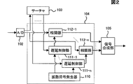
図2は、図1における逆拡散タイミング生成及び逆拡散部104即ち、信号復調部の詳細構成ブロック図である。同図において、信号復調部は拡散符号発生器110、複数の遅延制御部111−1〜111−n及び、対応する複数の相関器112−1〜112−nによって構成されている。
拡散符号発生器110は逆拡散のための符号を発生し、複数の遅延制御部111−1〜111−nはサーチャ103によって検出されたマルチパスのタイミングt1〜tNのそれぞれに対応する複数の相関器112−1〜112−nの遅延動作を制御する。各相関器112−1〜112−nは対応する遅延制御部111−1〜111−nによって制御される逆拡散タイミングに対応してA/D変換部102からの受信信号に対する逆拡散を行う。
これにより、相関器112−1〜112−nは、それぞれ逆拡散信号1〜逆拡散信号Nを信号合成部105に与え、信号合成部105はそれらの信号を合成して復調信号を出力する。
かかる逆拡散信号にはそれぞれのマルチパスの伝搬路係数に対応するチャネル推定用信号も含まれる。
以上のように、例えば図2においてはマルチパスの各パスのタイミングそのものを用いて逆拡散が行われる。あるタイミングで逆拡散をした場合には、そのタイミング以外のパスに対応する信号は全て干渉となる。特にCDMA方式の基地局からの下りリンクで複数のチャネルに対して直交拡散符号を用いているような場合には、マルチパス干渉のために受信特性が劣化するという問題が存在した。
かかる点に鑑み、本発明者は、特許出願2001−332510号により、マルチパス環境でスペクトラム拡散方式を用いる場合に、マルチパス干渉を抑圧できるレイク受信機を先に提案した。
ここで、かかる先に提案したレイク受信機の概略構成を説明する。図3は、先に提案したマルチパス環境でスペクトラム拡散通信システムを構成するレイク受信機の原理構成ブロック図である。
図3において、パスタイミング検出手段1は、例えば図1、図2のパスサーチャ103に相当するものであり、マルチパスのパスタイミング、例えばN個のパスのタイミングを検出する。
逆拡散タイミング設定手段2は、検出されたパスのタイミングを逆拡散のタイミング即ち、逆拡散符号を乗算して拡散符号化信号を復号するタイミングとして設定する。同時に、任意の2つのパスのタイミングの遅延時間分だけ、当該2つのパスのうちの一方のパスのタイミングを中心として、他方のパスのタイミングと時間軸上で対称の位置にある2つのタイミングを逆拡散のタイミングとするように、2つのパスの組合わせの全てに対して設定する。
複数の相関器3−1〜3−nは、設定された各タイミングに対応して送信側から送られた信号の、例えばA/D変換結果の信号の逆拡散信号をそれぞれ求める。信号合成手段4は複数の相関器3−1〜3−nの出力を合成し、復調信号を出力する。
このように、先の出願で提案した発明においては、選択した2つのパス情報のみを使って再生したマルチパス干渉相関信号(MICS)を使って、希望信号に含まれる干渉成分を低減している。
発明の概要
しかし、上記のように先願発明では、干渉成分を再生する際に選択した2パスのみの情報しか利用していなかったために、パス数の増加に伴って、干渉成分低減の効果が少なくなっていくという欠点が認められる。即ち、着目した2パス以外のパスに含まれているはずの情報を有効に利用できていない。
したがって、本発明の目的はかかる先願発明の不都合を改善し得るスペクトラム拡散レイク受信機を提供することにある。
そして、かかる本発明の目的を達成するスペクトラム拡散レイク受信機の第1の態様は、スペクトラム拡散通信システムを構成するスペクトラム拡散レイク受信機において、Nパスの直接スペクトラム拡散信号の受信時に、前記Nパスのそれぞれの受信タイミングti(i=1〜N)を検出するタイミング検出手段と、前記タイミング検出手段により検出される受信タイミングti(i=1〜N)から得られるタイミングti,j,kを逆拡散のタイミングとして設定する逆拡散タイミング設定手段と、前記逆拡散タイミング設定手段により設定された各タイミングに対応して受信信号の逆拡散信号をそれぞれ求める複数の相関器と、前記複数の相関器の出力を合成する信号合成手段とを有することを特徴とする。
上記本発明の目的を達成するスペクトラム拡散レイク受信機の第2の態様は、第1の態様において、更に、前記相関器と信号合成手段との間に、パスk(k≠j)のマルチパス干渉信号(mics(i,j,k))を式(1)により合成して
![]()
さらに、上記本発明の目的を達成するスペクトラム拡散レイク受信機の第3の態様は、第2の態様において、前記マルチパス干渉信号(mics(i,j,k))を合成する際、前記式(1)の係数ri,j,r′kを式(2)、式(3)により求め、
として、

上記本発明の目的を達成するスペクトラム拡散レイク受信機の第4の態様は、第2の態様において、前記マルチパス干渉信号(mics(i,j,k))を合成する際、前記マルチパス干渉信号(mics(i,j,k))の雑音を一定として近似し、前記式(1)の係数ri,j,r′kを式(4)、式(5)により求め、
上記本発明の目的を達成するスペクトラム拡散レイク受信機の第5の態様は、第2乃至4の態様のいずれかにおいて、更に前記干渉MICS(i,j)を減ずる回路は、電力の大きな複数個のパスを選択する回路を有し、前記選択されたパスに対して、前記マルチパス干渉信号(mics(i,j,k))の合成、及び前記干渉MICS(i,j)を減ずる処理を行うことを特徴とする。
上記本発明の目的を達成するスペクトラム拡散レイク受信機の第6の態様は、第2の態様において、前記i番目のパスから前記干渉MICS(i,j)を減ずる回路は、電力の大きな複数個のパスiを選択して、前記選択されたパスの数に対してのみ備えられることを特徴とする。
上記本発明の目的を達成するスペクトラム拡散レイク受信機の第7の態様は、第2乃至6のいずれかの態様において、前記逆拡散タイミング設定手段により、前記逆拡散のタイミングti,j,kと、受信タイミングtiの一致を検知し、一致が検知されたパスに対して前記マルチパス干渉信号(mics(i,j,k))の合成、及び前記干渉MICS(i,j)を減ずる処理を行わないことを特徴とする。
上記本発明の目的を達成するスペクトラム拡散レイク受信機の第8の態様は、第2乃至6のいずれかの態様において、更に、前記干渉MICS(i,j)を減ずる回路と信号合成手段との間にレベル補償回路を設け、前記レベル補償回路で前記干渉MICS(i,j)を減ずる回路における干渉低減後の信号の大きさを補正して、雑音の大きさを一定とすることを特徴とする。
さらに、上記本発明の目的を達成するスペクトラム拡散レイク受信機の第9の態様は、第1の態様において、更に、前記相関器の前段に、パスk(k≠j)のマルチパス干渉信号(mics(i,j,k))を式(1)により合成して
![]()
また、上記本発明の目的を達成するスペクトラム拡散レイク受信機の第10の態様は、第9の態様において、更に前記干渉MICS(i,j)を減ずる回路は、電力の大きな複数個のパスを選択する回路を有し、前記選択されたパスに対して、前記マルチパス干渉信号(mics(i,j,k))の合成、及び前記干渉MICS(i,j)を減ずる処理を行うことを特徴とする。
さらにまた、上記本発明の目的を達成するスペクトラム拡散レイク受信機の第11の態様は、第9の態様において、前記i番目のパスから前記干渉MICS(i,j)を減ずる回路は、電力の大きな複数個のパスiを選択して、前記選択されたパスの数に対してのみ備えられることを特徴とする。
本発明の特徴は、以下の図面に従い説明される発明の実施の形態例から更に明らかになる。Spread spectrum or spread spectrum communication systems are widely used as the most basic technology of mobile communication. In the direct spread (DS) system as the simplest model of spread spectrum communication, a PN signal having a chip width Tc of about 1/100 to 1/1000 is modulated as a spread signal with respect to the period T of the information signal to be transmitted. In other words, the spectrum is expanded by multiplication and transmitted to the receiving side.
On the receiving side, a signal component is detected from the signal buried in noise by despreading. Despreading is basically performing demodulation by multiplying the received signal by the same PN signal having the same phase as the PN signal in the received signal.
However, in a multipath environment where there are many reflected waves in addition to direct waves, it is necessary to detect correct signal components by appropriately combining signals received with various delay time differences.
One of such conventional techniques is a rake method. “Lake” means “deku” in English, and the rake method is a diversity method that collects signal power dispersed by delay dispersion of the transmission line into one and synthesizes the maximum ratio, as in “deku”.
A conventional rake receiver uses a known signal to find the timing of multiple paths where a multipath arrives, informs the demodulator of this timing, and the demodulator performs despreading at this timing to convert the multipath signal. The desired signal is demodulated by combining.
FIG. 1 is a block diagram showing an example of the overall configuration of a rake receiver as a mobile communication terminal, for example. In the figure, the receiver includes an
Further, a
The
FIG. 2 is a detailed block diagram of the despreading timing generation and despreading
The
Thus, correlators 112-1 to 112-n provide
Such despread signals also include channel estimation signals corresponding to the respective multipath channel coefficients.
As described above, for example, in FIG. 2, despreading is performed using the timing of each path of the multipath. When despreading is performed at a certain timing, all signals corresponding to paths other than the timing cause interference. In particular, when orthogonal spreading codes are used for a plurality of channels in the downlink from a CDMA base station, there is a problem that reception characteristics deteriorate due to multipath interference.
In view of this point, the present inventor previously proposed a rake receiver capable of suppressing multipath interference when a spread spectrum method is used in a multipath environment according to Japanese Patent Application No. 2001-332510.
Here, the schematic configuration of the rake receiver proposed above will be described. FIG. 3 is a block diagram of the principle configuration of a rake receiver that constitutes a spread spectrum communication system in the previously proposed multipath environment.
In FIG. 3, a path
The despreading
The plurality of correlators 3-1 to 3-n obtain, for example, despread signals of signals transmitted from the transmission side corresponding to the set timings, for example, A / D conversion result signals. The
As described above, in the invention proposed in the previous application, the interference component included in the desired signal is reduced using the multipath interference correlation signal (MICS) reproduced using only the selected two path information. .
SUMMARY OF THE INVENTION However, as described above, in the invention of the prior application, only the information on the two paths selected when reproducing the interference component was used. Therefore, the effect of reducing the interference component is increased as the number of paths increases. There is a drawback that it will decrease. That is, information that should be included in paths other than the focused two paths cannot be used effectively.
Accordingly, an object of the present invention is to provide a spread spectrum rake receiver that can improve the disadvantages of the prior invention.
The first aspect of the spread spectrum rake receiver that achieves the object of the present invention is the spread spectrum rake receiver that constitutes the spread spectrum communication system. each reception timing t i (i = 1 to N) and the timing detecting means for detecting the timing t i obtained from the reception timing t i detected by said timing detecting means (i = 1~N), j of despreading timing setting means for setting k as a despreading timing; a plurality of correlators that respectively obtain a despread signal of a received signal corresponding to each timing set by the despreading timing setting means; Signal synthesizing means for synthesizing the output of the correlator.
The second aspect of the spread spectrum rake receiver that achieves the object of the present invention is the multipath of the path k (k ≠ j) between the correlator and the signal synthesis means in the first aspect. The interference signal (mics (i, j, k)) is synthesized by equation (1)
![]()
Furthermore, a third aspect of the spread spectrum rake receiver that achieves the object of the present invention described above, in the second aspect, when the multipath interference signal (mics (i, j, k)) is synthesized, The coefficients r i, j and r ′ k of (1) are obtained by the equations (2) and (3),
As
In a fourth aspect of the spread spectrum rake receiver that achieves the object of the present invention, in the second aspect, when the multipath interference signal (mics (i, j, k)) is synthesized, the multipath interference The noise of the signal (mics (i, j, k)) is approximated as constant, and the coefficients r i, j , r ′ k of the above equation (1) are obtained by the equations (4) and (5),
In a fifth aspect of the spread spectrum rake receiver that achieves the object of the present invention, in any one of the second to fourth aspects, a circuit that further reduces the interference MICS (i, j) includes a plurality of high power units. And a process of reducing the interference MICS (i, j) with respect to the selected path by combining the multipath interference signal (mics (i, j, k)). It is characterized by performing.
According to a sixth aspect of the spread spectrum rake receiver that achieves the object of the present invention, in the second aspect, a circuit that subtracts the interference MICS (i, j) from the i-th path includes a plurality of high-power circuits. Path i is selected and provided only for the number of the selected paths.
The seventh aspect of the spread spectrum rake receiver that achieves the object of the present invention is the despreading timing t i, j, k by the despreading timing setting means in any of the second to sixth aspects. And the reception timing t i is detected, and the synthesis of the multipath interference signal (mics (i, j, k)) and the interference MICS (i, j) are reduced with respect to the path where the match is detected. The processing is not performed.
According to an eighth aspect of the spread spectrum rake receiver that achieves the object of the present invention described above, in any one of the second to sixth aspects, a circuit for reducing the interference MICS (i, j) and a signal synthesis unit are further provided. A level compensation circuit is provided in between, and the level of noise is corrected by correcting the magnitude of the signal after interference reduction in the circuit for reducing the interference MICS (i, j) by the level compensation circuit. To do.
Furthermore, a ninth aspect of the spread spectrum rake receiver that achieves the above object of the present invention is the first aspect, further comprising a multipath interference signal of a path k (k ≠ j) in a stage preceding the correlator ( mics (i, j, k)) is synthesized by equation (1)
![]()
The tenth aspect of the spread spectrum rake receiver that achieves the object of the present invention is the ninth aspect, wherein the circuit for reducing the interference MICS (i, j) further comprises a plurality of paths with high power. A circuit for selecting, and performing a process of combining the multipath interference signal (mics (i, j, k)) and reducing the interference MICS (i, j) for the selected path. Features.
Furthermore, an eleventh aspect of the spread spectrum rake receiver that achieves the object of the present invention is the ninth aspect, wherein the circuit that subtracts the interference MICS (i, j) from the i-th path A plurality of large paths i are selected and provided only for the number of the selected paths.
The features of the present invention will become more apparent from the embodiments of the present invention described with reference to the following drawings.
図1は、移動通信端末としてのレイク受信機の全体構成例を示すブロック図である。
図2は、図1における逆拡散タイミング生成及び逆拡散部104即ち、信号復調部の詳細構成ブロック図である。
図3は、先に提案したマルチパス環境でスペクトラム拡散通信システムを構成するレイク受信機の原理構成ブロック図である。
図4は、CDMA(符号拡散多重アクセス)移動端末で受信される2パスの信号のタイミングを示す図である。
図5は、Nパス信号と、パスiに含まれるパスjの干渉の低減に利用できる複数のマルチパス干渉相関タイミング(MICTs)を示す図である。
図6は、本発明を適用するCDMA受信機の構成例を示す図である。
図7は、図6における合成部27の構成例を示す図である。
図8は、本発明の他の実施の形態例を示す図である。
図9は、マルチパス干渉低減処理回路28の詳細構成を示す図である。
図10は、MICS部280−1〜280−Nの詳細を280−iを代表として示す図である。
図11は、MRC128の構成例を示す図である。
図12は、MICS部280−iの他の構成例を示す図である。
図13は、実施の形態例として、MIXR回路28の前段にセレクタ回路31を設けている構成を示す図である。
図14は、MICS部280−iの更に他の構成例を示す図である。
図15は、MIXR部28と後段のレイク合成部27との間にレベル訂正部32を設ける構成を示す図である。
図16は、本発明の更に他の実施の形態例を示すずである。
図17は、図16の構成において、MIXR部28を構成するMICS部280−iの構成を示す図である。FIG. 1 is a block diagram showing an example of the overall configuration of a rake receiver as a mobile communication terminal.
FIG. 2 is a detailed block diagram of the despreading timing generation and
FIG. 3 is a block diagram of the principle configuration of a rake receiver that constitutes a spread spectrum communication system in the previously proposed multipath environment.
FIG. 4 is a diagram illustrating the timing of a two-path signal received by a CDMA (Code Spread Multiple Access) mobile terminal.
FIG. 5 is a diagram illustrating N-path signals and a plurality of multipath interference correlation timings (MICTs) that can be used for reducing interference of path j included in path i.
FIG. 6 is a diagram illustrating a configuration example of a CDMA receiver to which the present invention is applied.
FIG. 7 is a diagram illustrating a configuration example of the
FIG. 8 is a diagram showing another embodiment of the present invention.
FIG. 9 is a diagram showing a detailed configuration of the multipath interference
FIG. 10 is a diagram showing details of the MICS units 280-1 to 280 -N with 280-i as a representative.
FIG. 11 is a diagram illustrating a configuration example of the
FIG. 12 is a diagram illustrating another configuration example of the MICS unit 280-i.
FIG. 13 is a diagram showing a configuration in which a
FIG. 14 is a diagram illustrating still another configuration example of the MICS unit 280-i.
FIG. 15 is a diagram illustrating a configuration in which a level correction unit 32 is provided between the
FIG. 16 shows still another embodiment of the present invention.
FIG. 17 is a diagram showing the configuration of the MICS unit 280-i that constitutes the
ここで、本発明の実施の形態例の説明先立って、本発明の正しい理解のために先に説明した、本発明者による先願発明の原理について更に説明する。
マルチパスの信号をあるタイミングで逆拡散する時、干渉を生ずるパスの信号は、逆拡散信号の相互相関値と伝搬路の減衰係数などで決定される。逆拡散信号の相関値は、パスを経由して到着した信号のタイミングと、逆拡散のタイミングとの間の遅延で決まる定数となる。
図4にCDMA(符号拡散多重アクセス)移動端末で受信される2パスの信号のタイミングを示す。図中、・・YZABCD・・・は、各パスの信号タイミングを表すラベルであり、Aが正しい逆拡散タイミングであるとする。パス1とパス2のチャネルをそれぞれα1、α2とし、逆拡散タイミングをt1,t2、そのタイミングで逆拡散した信号をx1,x2と表記する。
ここで、特別なタイミングt0=t1−(t2−t1)を定め、タイミングt0で逆拡散した信号をx0とすると、x1,x0は、それぞれ次のように表記できる。
上記の信号x0は、受信信号Sの得られないタイミングで逆拡散したものであるが、その中にα1IZが含まれている。すなわち、x1の干渉成分α2IZと相関を有していることがわかる。かかる意味から、x0のような信号をパス1のパス2に対するマルチパス干渉相関信号(MICS :Multipath Interference Correlative Signal)と呼び、t0のようなタイミングをパス1のパス2に対するマルチパス干渉相関タイミング(MICT:Multipath Interference Correlative Timing)と呼ぶ。
x0がx1の干渉成分と相関を持つためにx1からx0に適切な係数rをかけて減ずることにより、x1の干渉成分を減らすことができる。
なお、ここで注意すべきは、x1に含まれるIZを全て消すように係数rを決めると、x0に含まれる別の干渉成分IYが増大する。このために却って干渉全体の大きさが増えてしまうことがある。したがって、最適な係数rは、元の干渉IZも残しつつ干渉全体の電力が最小になるように決めた係数とすることが必要である。
以上説明した先願発明においては、干渉成分を再生する際に選択した2パスのみの情報を利用している。したがって、着目した2パス以外のパスに含まれる情報を有効に利用し得ないものである。このために干渉成分減少効果が小さいものとなる。
したがって、本発明はかかる先願発明の欠点を解消するものであり、干渉成分を再生するために、干渉源を除く全てのパスを使うことで干渉再生精度を高めるものである。かかる本発明の原理について、以下に説明する。
図5にNパス信号と、パスiに含まれるパスjの干渉の低減に利用できる複数のマルチパス干渉相関タイミング(MICTs)を示す。パスiのタイミングで逆拡散した信号は次のように表される。
![]()
ここで、パスiとj以外のパスについても着目すると、それぞれのパスからΔtシフトさせたタイミングti,j,k(kはjを除く1〜N)で逆拡散することにより、タイミングti,j,iと同様にIi,jと相関のある信号が得られる。ti,j,kと、ti,j,kで逆拡散した信号は次のように表される。
上記の本発明の原理に基づき、次に本発明の実施の形態例について説明する。
図6は、本発明を適用するCDMA受信機の構成例である。アンテナ20により受信されたCDMA信号は、ダウンコンバータ21によりベースバンド信号に変換される。
ベースバンド信号は、AGC増幅器22を通してA/D変換器23に入力される。ここで、デジタル信号に変換され、パスの数nに対応する逆拡散回路部24−1〜24−n及び、パスサーチ部25に入力される。
パスサーチ部25において、受信信号からマルチパスのそれぞれのパスのタイミングが得られる。このパスタイミングに基づき、次の式により逆拡散タイミングti,j,k,nが、タイミング生成回路26で生成される。
![]()
図7は、図6における合成部27の構成例である。ここでは、実施例としてMMSE受信機の構成を示している。したがって、合成部27は、MMSE係数生成部270を有する。
MMSE係数生成部270では、受信信号のS/Nを最大とする合成係数を求める。これを各フィンガー対応の乗算器271−1〜271−nに係数として乗じる。更にこれら乗算器271−1〜271−nの出力を加算する加算器272を有して構成される。これにより、加算器272から受信信号のS/Nを最大とする出力を得ることができる。
かかる本発明を適用する図6の構成は、有効な逆拡散タイミングを容易に求めることができるために、少ない逆拡散フィンガーで好ましい効果を得ることができる。
図8は、本発明の他の実施の形態例である。図6の実施の形態例構成に対し、逆拡散回路部24−1〜24−nとレイク合成部27の間にマルチパス干渉低減処理(MIXR:Multipath Interference Exchange reduction)回路28を設けている。このマルチパス干渉低減処理回路28により各フィンガーの干渉が低減される。
図9は、マルチパス干渉低減処理回路28の詳細構成を示す。パスiに含まれるパスjによる干渉をMICS部280−1〜280−Nで再生し、MICS部280−1〜280−Nの全ての出力を加算器281で加算し、更に、その加算結果をパスiの信号から減算器282で減ずることで干渉を低減している。
上記のMICS部280−1〜280−Nのそれぞれは、パスiに,パスjから入る(j≠i)の干渉を再生している。
図10にMICS部280−1〜280−Nの詳細を280−iを代表として示す。パスサーチ部25により得られたレイクパスのタイミング情報tiを元にタイミング生成回路26iでマルチパス干渉相関タイミング(MICT)ti,j,kを次の式により求める。
![]()
図11は、MRC128の構成例を示す。MRC128では、チャネル推定部29から得られるチャネル推定値αi(i=1〜N)と、レベル測定部30から得られる雑音電力n2とに基づき係数生成部128−1で得られる適切な係数r′kをmics(i,j,k)に乗算器128−2iで乗算し、これを加算器128−3で加算する。さらに、乗算器128−4で加算器128−3の出力に係数ri,jを乗算してMICS(i,j)を得る。したがって、MICS(i,j)は次の式により表される。
![]()
ここで、図11のMRC部128の処理において、MICS(i,j)を求める時に、mics(i,j,k)に乗じる係数r′kを、雑音を一定と近似して次のように求める。
図12に、MICS部280−iの他の構成例を示す。図10との比較において、特徴としてセレクタ部129を有する。セレクタ部129は、チャネル推定部29からのチャネル推定値に基づきパスの大きさを判断し、大きなパスkについてのみ、mics(i,j,k)を求めることで性能を大きく劣化させることなく、回路規模や処理量を削減することができる。
なお、図12の構成例では、逆拡散回路104−ia,ibからk=s1,s2の2つを選択している。
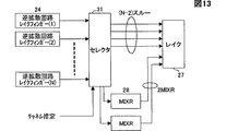
図8におけるMIXR回路28のMIXR処理は大きなパスに適用すると効果が大きい。図13は、実施の形態例として、MIXR回路28の前段にセレクタ回路31を設けている構成を示す。セレクタ部31により、チャネル推定部29からのチャネル推定値に基づいてパスの大きさを判断し、大きなパスに関してのみ、MIXR処理を行うように制御する。
MIXR処理の対象とならないパスについては、そのままレイク処理を行うように直接にレイク回路27に導くようにしている。図13の構成例では、2つのパスをMIXR処理し、その他の(N−2)パスは何もしない構成である。
図14は、MICS部280−iの更に他の構成例を示す。MIXR処理する際に、mics(i,j,k)の逆拡散タイミングti,j,kが希望信号のタイミングtiと重なる場合がある。例えば、tiが等間隔で並んでいる場合、タイミングti,j,kのいずれかのtiと重なってしまうことがある。そこで、タイミング生成回路26iで、タイミングti,j,kがtiと一致する場合を検出し、一致する場合の信号をスイッチ130−1〜130−Nで阻止する。これにより特性劣化を防ぐことができる。
かかる動作に対応するように、図14の実施の形態例におけるタイミング生成部26iは、タイミングti,j,kを生成するとともに、tiとの比較を行い、一致あるいは、一致に等しい近時にある場合は、該当のタイミングに対応するmics(i,j,k)の出力部のスイッチ130−iを制御して、MRC部128に入力されることを阻止する。
これにより、信号と重複したタイミングのmics(i,j,k)をマスクすることができる。
ここで、図8において、(1)MIXR部28の後段のレイク合成部27では各フィンガの雑音レベルがどのフィンガでも一定である。また、(2)レイク合成部27から図示しない誤り訂正部に渡されるデータは振幅が信号の尤度になっているということが処理の前提である。
多くの場合、レイク合成部27では誤り訂正部への適正な信号を生成するために上記のとおり、MIXR部28の後段のレイク合成部27では各フィンガの雑音レベルがどのフィンガでも一定である。しかし、各レイクフィンガに対しMIXR処理をした場合、各フィンガの干渉を含む雑音のレベルが小さくなり、どのフィンガでも同程度であった雑音電力にばらつきが生じ、その結果レイク合成や誤り訂正の効果が十分に発揮できないことが在る。
このために、図15に示す構成のように、MIXR部28と後段のレイク合成部27との間にレベル補償部32を設けることが好ましい。これにより、MIXR処理後の信号を適切に増幅して雑音電力をMIXR処理前と同様にすすることができる。
図16は、本発明の更に他の実施の形態例である。図8に示す実施の形態例との比較において、MIXR部28と逆拡散回路部24の位置を逆にされていることに特徴を有する。
かかる図16の構成において、MIXR部28を構成するMICS部280−iは図17に示す構成となる。図10との比較において、逆拡散回路104−iが遅延回路105−iに置き換えられている。
このように、MIXR部28を逆拡散回路部24の前におくことにより、回路構成を簡単化することができる。
発明の利用可能性
以上実施の形態例について説明したように、本発明の適用により、パス数の増加する場合せあっても効果的な干渉雑音低減が可能である。
これにより、マルチパス環境での伝搬路の多重反射により様々な遅延時間差を有してアンテナに到来する信号の時間領域での効果的な最大比合成を行うレイク受信機が提供可能である。Here, prior to the description of the embodiments of the present invention, the principle of the prior invention by the present inventor described above for the correct understanding of the present invention will be further described.
When the multipath signal is despread at a certain timing, the signal of the path causing the interference is determined by the cross-correlation value of the despread signal and the attenuation coefficient of the propagation path. The correlation value of the despread signal is a constant determined by the delay between the timing of the signal arriving via the path and the despread timing.
FIG. 4 shows the timing of a two-path signal received by a CDMA (Code Spread Multiple Access) mobile terminal. In the figure,... YZABCD... Is a label indicating the signal timing of each path, and A is the correct despreading timing. The channels of
Here, if a special timing t 0 = t 1 − (t 2 −t 1 ) is determined and a signal despread at the timing t 0 is x 0 , x 1 and x 0 can be expressed as follows: .
The signal x 0 is despread at the timing when the received signal S is not obtained, and α 1 I Z is included therein. That is, it can be seen that there is a correlation with the interference component α 2 I Z of x 1 . From this sense, the multipath interference correlation signal a signal, such as x 0 for the
x 0 is by reducing over an appropriate coefficient r from x 1 to x 0 in order to have a correlation with the interference component of x 1, it is possible to reduce the interference component of x 1.
It should be noted that if the coefficient r is determined so as to eliminate all I Z included in x 1 , another interference component I Y included in x 0 increases. For this reason, the size of the entire interference may increase. Accordingly, the optimal coefficient r, it is necessary to factor decided so that the original interference I Z also power the entire interference while leaving is minimized.
In the invention of the prior application described above, information of only two paths selected when reproducing the interference component is used. Therefore, information included in paths other than the focused two paths cannot be used effectively. For this reason, the interference component reduction effect is small.
Therefore, the present invention eliminates the disadvantages of the prior invention, and improves the interference reproduction accuracy by using all paths except the interference source to reproduce the interference component. The principle of the present invention will be described below.
FIG. 5 shows N-path signals and a plurality of multipath interference correlation timings (MICTs) that can be used to reduce interference of path j included in path i. A signal despread at the timing of path i is expressed as follows.
![]()
Here, also paying attention to a path other than the path i and j, the timing t i obtained by Δt shifted from each path, j, k (k is 1~N excluding j) by despreading at the timing t i , J, i , a signal correlated with I i, j is obtained. The signals despread by ti , j, k and ti , j, k are expressed as follows.
Based on the principle of the present invention described above, an embodiment of the present invention will be described below.
FIG. 6 is a configuration example of a CDMA receiver to which the present invention is applied. The CDMA signal received by the
The baseband signal is input to the A /
In the
![]()
FIG. 7 is a configuration example of the combining
The MMSE
The configuration of FIG. 6 to which the present invention is applied can easily obtain an effective despreading timing, and therefore, a favorable effect can be obtained with a small number of despreading fingers.
FIG. 8 shows another embodiment of the present invention. 6, a multipath interference reduction process (MIXR: Multipath Interference Exchange Reduction)
FIG. 9 shows a detailed configuration of the multipath interference
Each of the MICS units 280-1 to 280-N reproduces interference that enters the path i from the path j (j ≠ i).
FIG. 10 shows details of the MICS units 280-1 to 280 -N with 280-i as a representative. Path search unit multipath interference correlation timing based on the timing information t i obtained Reikupasu by 25 by the timing generating circuit 26i (MICT) t i, j , a k determined by the following equation.
![]()
FIG. 11 shows a configuration example of the
![]()
Here, in the processing of the
FIG. 12 shows another configuration example of the MICS unit 280-i. In comparison with FIG. 10, a
In the configuration example of FIG. 12, two of k = s1 and s2 are selected from the despreading circuits 104-ia and ib.
The MIXR process of the
A path that is not a target of the MIXR process is directly guided to the
FIG. 14 shows still another configuration example of the MICS unit 280-i. When MIXR processing, mics (i, j, k) despreading timing t i of, j, k in some cases overlap with the timing t i of the desired signal. For example, if t i are arranged at equal intervals, may sometimes overlap timing t i, j, and either t i of k. Therefore, the
In order to correspond to such an operation, the
Thereby, mics (i, j, k) at the same timing as the signal can be masked.
Here, in FIG. 8, (1) in the
In many cases, as described above, in order to generate an appropriate signal to the error correction unit in the
For this purpose, it is preferable to provide a level compensation unit 32 between the
FIG. 16 shows still another embodiment of the present invention. 8 is characterized in that the positions of the
In the configuration of FIG. 16, the MICS unit 280-i configuring the
Thus, the circuit configuration can be simplified by placing the
Applicability of the Invention As described above with reference to the embodiments, the application of the present invention can effectively reduce interference noise even when the number of paths increases.
Thus, it is possible to provide a rake receiver that performs effective maximum ratio combining in the time domain of signals arriving at the antenna with various delay time differences due to multiple reflection of propagation paths in a multipath environment.
Claims (10)
前記逆拡散タイミング設定手段が,
前記タイミング検出手段により検出される受信タイミングt i (i=1〜N)からi番目のパスの逆拡散値に入る,j番目(j=1〜N,j≠i)のパスからの,干渉と相関を有する逆拡散値が得られるタイミングt i,j,k (k=1〜N,k≠j)を,前記逆拡散のタイミングとして設定し,
前記タイミングt i,j,k は,i番目のパスにj番目のパスが与える干渉をk番目のパスで再生するタイミングであり,t i,j,k =t i− t j +t k で与えられる,
ことを特徴とするレイク受信機。 Upon receipt of 3 or more direct sequence spread spectrum signals of N paths, and timing detecting means for detecting each of a received timing t i of the N paths (i = 1 to N), the reception timing detected by said timing detecting means Despreading timing setting means for setting a despreading timing based on a plurality of correlators for respectively obtaining a despread signal of a received signal corresponding to each timing set by the despreading timing setting means, and the plurality of correlations A rake receiver for use in a spread spectrum communication system, having a signal synthesis means for synthesizing the output of the detector ,
The despreading timing setting means comprises:
Interference from the j th (j = 1 to N, j ≠ i) path that enters the despread value of the i th path from the reception timing t i (i = 1 to N) detected by the timing detection means. And a timing t i, j, k (k = 1 to N, k ≠ j) at which a despread value having a correlation is obtained is set as the despread timing,
The timing t i, j, k is the i th path j th path gives interference to a timing of reproducing the k-th path, given by t i, j, k = t i- t j + t k ,
Rake receiver characterized by that.
更に,前記相関器と信号合成手段との間に,
パスk(k≠j)の,タイミングt i,j,k で逆拡散により得られる信号であるマルチパス干渉信号(mics(i,j,k))を式(1)により合成し,
前記合成により得られる前記干渉MICS(i,j)を,i番目のパスのタイミングで逆拡散した信号
前記マルチパス干渉信号(mics(i,j,k))を合成する際,前記式(1)の係数r i,j ,r' k をそれぞれ式(2),式(3)により求め,
(但し,(I/N) j は再生しようとする干渉とそれ以外の電力の比,n 2 は雑音電力)
最大比合成により合成する,
ことを特徴とするレイク受信機。 In claim 1,
Furthermore, between the correlator and the signal synthesis means,
Path k of (k ≠ j), the timing t i, j, multipath interference signal is a signal obtained by despreading with k (mics (i, j, k)) was synthesized by the formula (1),
A signal obtained by despreading the interference MICS (i, j) obtained by the synthesis at the timing of the i-th path
Wherein the synthesis of the multipath interference signal (mics (i, j, k)), coefficients r i, j, r 'k each type of the formula (1) (2), calculated by the equation (3),
(Where (I / N) j is the ratio of interference to be reproduced and other power, and n 2 is noise power)
Synthesize by maximum ratio synthesis,
Rake receiver characterized by that.
更に,前記相関器と信号合成手段との間に,
パスk(k≠j)の,タイミングt i,j,k で逆拡散により得られる信号であるマルチパス干渉信号(mics(i,j,k))を式(1)により合成し,
前記合成により得られる前記干渉MICS(i,j)を,i番目のパスのタイミングで逆拡散した信号
前記マルチパス干渉信号(mics(i,j,k))を合成する際,前記マルチパス干渉信号(mics(i,j,k))の雑音を一定として近似し,前記式(1)の係数ri,j,r'kを式(4),式(5)により求め,
(但し,(I/N) j は再生しようとする干渉とそれ以外の電力の比)
最大比合成により合成することを特徴とするレイク受信機。 In claim 1 ,
Furthermore, between the correlator and the signal synthesis means,
A multipath interference signal (mics (i, j, k)), which is a signal obtained by despreading at the timing t i, j, k of the path k (k ≠ j) , is synthesized by Equation (1),
A signal obtained by despreading the interference MICS (i, j) obtained by the synthesis at the timing of the i-th path
When synthesizing the multipath interference signal (mics (i, j, k)), the noise of the multipath interference signal (mics (i, j, k)) is approximated as a constant, and the coefficient of the equation (1) r i, j , r ′ k is obtained from Equation (4) and Equation (5),
(However, (I / N) j is the ratio of interference to be reproduced and other power)
Rake receiver characterized by combining by maximum ratio combining.
更に前記干渉MICS(i,j)を減ずる回路は,電力の大きな複数個のパスを選択する回路を有し,
前記選択されたパスに対して,前記マルチパス干渉信号(mics(i,j,k))の合成,及び前記干渉MICS(i,j)を減ずる処理を行うことを特徴とするレイク受信機。 In any of claims 2 to 4,
Further, the circuit for reducing the interference MICS (i, j) has a circuit for selecting a plurality of paths with large power,
A rake receiver characterized by performing a process of combining the multipath interference signal (mics (i, j, k)) and reducing the interference MICS (i, j) on the selected path.
前記干渉MICS(i,j)を減ずる回路は,電力の大きな複数個のパスiを選択して,前記選択されたパスに対してのみ備えられることを特徴とするレイク受信機。 In claim 2 or 3 ,
Before Kihi Wataru MICS (i, j) circuits to reduce the, choose a larger plurality of path i of power, rake receiver, characterized in that provided only for the selected path.
前記逆拡散タイミング設定手段により,前記逆拡散のタイミングti,j,kと,受信タイミングtiの一致を検知し,一致が検知されたパスに対して前記マルチパス干渉信号(mics(i,j,k))の合成,及び前記干渉MICS(i,j)を減ずる処理を行わないことを特徴とするレイク受信機。 In any of the claims 2-5,
The despreading timing setting means detects a match between the despread timing t i, j, k and the reception timing t i , and the multipath interference signal (mics (i, j, k)) and a process for reducing the interference MICS (i, j) is not performed.
更に,前記干渉MICS(i,j)を減ずる回路と信号合成手段との間にレベル補償回路を設け,前記レベル補償回路で前記干渉MICS(i,j)を減ずる回路における干渉低減後の信号の大きさを補正して,雑音の大きさを一定とすることを特徴とするレイク受信機。 In any of the claims 2-5,
Further, a level compensation circuit is provided between the circuit for reducing the interference MICS (i, j) and the signal synthesis means, and the signal after interference reduction in the circuit for reducing the interference MICS (i, j) by the level compensation circuit is provided. A rake receiver characterized by making the noise level constant by correcting the magnitude.
更に,前記相関器の前段に,
パスk(k≠j)の,タイミングt i,j,k で逆拡散により得られる信号であるマルチパス干渉信号(mics(i,j,k))を式(1)により合成し,
前記合成により得られる前記干渉MICS(i,j)を,i番目のパスのタイミングで逆拡散した信号
前記マルチパス干渉信号(mics(i,j,k))を合成する際,前記式(1)の係数r i,j ,r' k をそれぞれ式(2),式(3)により求め,
(但し,(I/N) j は再生しようとする干渉とそれ以外の電力の比,n 2 は雑音電力)最大比合成により合成する,
ことを特徴とするレイク受信機。 In claim 1,
Furthermore, before the correlator,
Path k of (k ≠ j), the timing t i, j, multipath interference signal is a signal obtained by despreading with k (mics (i, j, k)) was synthesized by the formula (1),
A signal obtained by despreading the interference MICS (i, j) obtained by the synthesis at the timing of the i-th path
When synthesizing the multipath interference signal (mics (i, j, k)), the coefficients r i, j and r ′ k of the equation (1) are obtained by the equations (2) and (3), respectively.
(Where (I / N) j is the ratio of the interference to be reproduced and other power, and n 2 is the noise power).
Rake receiver characterized by that.
更に前記干渉MICS(i,j)を減ずる回路は,電力の大きな複数個のパスを選択する回路を有し,
前記選択されたパスに対して,前記マルチパス干渉信号(mics(i,j,k))の合成,及び前記干渉MICS(i,j)を減ずる処理を行うことを特徴とするレイク受信機。 In claim 8 ,
Further, the circuit for reducing the interference MICS (i, j) has a circuit for selecting a plurality of paths with large power,
A rake receiver characterized by performing a process of combining the multipath interference signal (mics (i, j, k)) and reducing the interference MICS (i, j) on the selected path.
前記i番目のパスから前記干渉MICS(i,j)を減ずる回路は,電力の大きな複数個のパスiを選択して,前記選択されたパスに対して備えられることを特徴とするレイク受信機。 In claim 8 ,
Circuit subtracting the interference MICS from the i-th path (i, j) is the rake reception by selecting a large plurality of path i of power, characterized in that provided for the selected path Machine.
Applications Claiming Priority (1)
| Application Number | Priority Date | Filing Date | Title |
|---|---|---|---|
| PCT/JP2002/009414 WO2004025860A1 (en) | 2002-09-13 | 2002-09-13 | Spread spectrum rake receiver |
Publications (2)
| Publication Number | Publication Date |
|---|---|
| JPWO2004025860A1 JPWO2004025860A1 (en) | 2006-01-12 |
| JP3926366B2 true JP3926366B2 (en) | 2007-06-06 |
Family
ID=31986102
Family Applications (1)
| Application Number | Title | Priority Date | Filing Date |
|---|---|---|---|
| JP2004535849A Expired - Fee Related JP3926366B2 (en) | 2002-09-13 | 2002-09-13 | Spread spectrum rake receiver |
Country Status (4)
| Country | Link |
|---|---|
| EP (1) | EP1548953B1 (en) |
| JP (1) | JP3926366B2 (en) |
| DE (1) | DE60233445D1 (en) |
| WO (1) | WO2004025860A1 (en) |
Families Citing this family (2)
| Publication number | Priority date | Publication date | Assignee | Title |
|---|---|---|---|---|
| JP4476031B2 (en) | 2004-06-11 | 2010-06-09 | 富士通株式会社 | Interference reduction apparatus and interference reduction method |
| EP2141822B1 (en) | 2007-04-20 | 2016-05-04 | Fujitsu Limited | Equalizer control apparatus, equalizer control method, and wireless terminal having that control apparatus |
Family Cites Families (1)
| Publication number | Priority date | Publication date | Assignee | Title |
|---|---|---|---|---|
| US6865218B1 (en) * | 2000-11-27 | 2005-03-08 | Ericsson Inc. | Multipath interference reduction for a CDMA system |
-
2002
- 2002-09-13 EP EP02760830A patent/EP1548953B1/en not_active Expired - Fee Related
- 2002-09-13 DE DE60233445T patent/DE60233445D1/en not_active Expired - Lifetime
- 2002-09-13 WO PCT/JP2002/009414 patent/WO2004025860A1/en active Application Filing
- 2002-09-13 JP JP2004535849A patent/JP3926366B2/en not_active Expired - Fee Related
Also Published As
| Publication number | Publication date |
|---|---|
| WO2004025860A1 (en) | 2004-03-25 |
| EP1548953A1 (en) | 2005-06-29 |
| JPWO2004025860A1 (en) | 2006-01-12 |
| EP1548953A4 (en) | 2006-02-01 |
| DE60233445D1 (en) | 2009-10-01 |
| EP1548953B1 (en) | 2009-08-19 |
Similar Documents
| Publication | Publication Date | Title |
|---|---|---|
| JP3305639B2 (en) | RAKE receiver in direct spread CDMA transmission system | |
| US8565287B2 (en) | Method and system for per-cell interference estimation for interference suppression | |
| JPH098776A (en) | Receiver, receiving method and multipath component channel coefficient evaluation device | |
| JPH09502593A (en) | Method and apparatus for identifying coded communication signals | |
| JPH10190528A (en) | Spread spectrum receiver | |
| JP3891373B2 (en) | Demodulator and demodulation method | |
| KR100652172B1 (en) | Cdma mobile station apparatus | |
| JP2003133999A (en) | Spread spectrum rake receiver | |
| EP1563621A1 (en) | Method and apparatus for rake combining based upon signal to interference noise ratio | |
| JP4476031B2 (en) | Interference reduction apparatus and interference reduction method | |
| JP2002232327A (en) | Path selection method and circuit used for receiver | |
| JP3886709B2 (en) | Spread spectrum receiver | |
| JP3926366B2 (en) | Spread spectrum rake receiver | |
| US7573934B2 (en) | Spread spectrum rake receiver | |
| JP2991236B1 (en) | Error estimation apparatus for direct-sequence reception data and direct-sequence reception apparatus | |
| KR100358349B1 (en) | Apparatus and Method of Group-wise Parallel Interference Cancellation for Multi-rate DS-CDMA Systems | |
| JP3691723B2 (en) | base station | |
| US7756191B2 (en) | Deconvolution searcher for wireless communication system | |
| JP3210914B2 (en) | Error estimation apparatus for direct-sequence received data and direct-sequence reception apparatus | |
| JP2930585B1 (en) | Signal receiving apparatus in DS-CDMA system | |
| JPH10117180A (en) | Code division multiple address demodulator | |
| KR100572675B1 (en) | Rake receiver and the method with finger equipment and the method using auto-interference cancellation technique | |
| JP2004289758A (en) | Interference reduction apparatus | |
| JPH11275061A (en) | Interference eliminating receiver | |
| JPH0795130A (en) | Spread spectrum signal receiver |
Legal Events
| Date | Code | Title | Description |
|---|---|---|---|
| A131 | Notification of reasons for refusal |
Free format text: JAPANESE INTERMEDIATE CODE: A131 Effective date: 20061205 |
|
| A521 | Written amendment |
Free format text: JAPANESE INTERMEDIATE CODE: A523 Effective date: 20070205 |
|
| TRDD | Decision of grant or rejection written | ||
| A01 | Written decision to grant a patent or to grant a registration (utility model) |
Free format text: JAPANESE INTERMEDIATE CODE: A01 Effective date: 20070227 |
|
| A61 | First payment of annual fees (during grant procedure) |
Free format text: JAPANESE INTERMEDIATE CODE: A61 Effective date: 20070227 |
|
| R150 | Certificate of patent or registration of utility model |
Ref document number: 3926366 Country of ref document: JP Free format text: JAPANESE INTERMEDIATE CODE: R150 Free format text: JAPANESE INTERMEDIATE CODE: R150 |
|
| FPAY | Renewal fee payment (event date is renewal date of database) |
Free format text: PAYMENT UNTIL: 20100309 Year of fee payment: 3 |
|
| FPAY | Renewal fee payment (event date is renewal date of database) |
Free format text: PAYMENT UNTIL: 20110309 Year of fee payment: 4 |
|
| FPAY | Renewal fee payment (event date is renewal date of database) |
Free format text: PAYMENT UNTIL: 20110309 Year of fee payment: 4 |
|
| FPAY | Renewal fee payment (event date is renewal date of database) |
Free format text: PAYMENT UNTIL: 20120309 Year of fee payment: 5 |
|
| FPAY | Renewal fee payment (event date is renewal date of database) |
Free format text: PAYMENT UNTIL: 20130309 Year of fee payment: 6 |
|
| FPAY | Renewal fee payment (event date is renewal date of database) |
Free format text: PAYMENT UNTIL: 20140309 Year of fee payment: 7 |
|
| LAPS | Cancellation because of no payment of annual fees |