JP3926041B2 - Image forming apparatus - Google Patents
Image forming apparatus Download PDFInfo
- Publication number
- JP3926041B2 JP3926041B2 JP21223898A JP21223898A JP3926041B2 JP 3926041 B2 JP3926041 B2 JP 3926041B2 JP 21223898 A JP21223898 A JP 21223898A JP 21223898 A JP21223898 A JP 21223898A JP 3926041 B2 JP3926041 B2 JP 3926041B2
- Authority
- JP
- Japan
- Prior art keywords
- toner
- image
- photosensitive drum
- developing device
- value
- Prior art date
- Legal status (The legal status is an assumption and is not a legal conclusion. Google has not performed a legal analysis and makes no representation as to the accuracy of the status listed.)
- Expired - Fee Related
Links
- 238000012546 transfer Methods 0.000 claims description 42
- 238000004140 cleaning Methods 0.000 claims description 21
- 230000002093 peripheral effect Effects 0.000 claims description 12
- 238000001514 detection method Methods 0.000 claims description 7
- 238000003384 imaging method Methods 0.000 description 10
- 238000003756 stirring Methods 0.000 description 8
- 210000000078 claw Anatomy 0.000 description 6
- 238000010586 diagram Methods 0.000 description 5
- 238000012545 processing Methods 0.000 description 5
- 239000000463 material Substances 0.000 description 3
- 230000003287 optical effect Effects 0.000 description 3
- 238000011161 development Methods 0.000 description 2
- 238000010438 heat treatment Methods 0.000 description 2
- 238000005192 partition Methods 0.000 description 2
- 238000011084 recovery Methods 0.000 description 2
- 238000000926 separation method Methods 0.000 description 2
- 229920003002 synthetic resin Polymers 0.000 description 2
- 239000000057 synthetic resin Substances 0.000 description 2
- 238000013019 agitation Methods 0.000 description 1
- 238000004891 communication Methods 0.000 description 1
- 230000007423 decrease Effects 0.000 description 1
- 238000007599 discharging Methods 0.000 description 1
- 230000000694 effects Effects 0.000 description 1
- 239000000835 fiber Substances 0.000 description 1
- 230000001678 irradiating effect Effects 0.000 description 1
- 239000004973 liquid crystal related substance Substances 0.000 description 1
- 238000012423 maintenance Methods 0.000 description 1
- 238000002844 melting Methods 0.000 description 1
- 230000008018 melting Effects 0.000 description 1
- 230000035699 permeability Effects 0.000 description 1
- 230000007723 transport mechanism Effects 0.000 description 1
- 238000011144 upstream manufacturing Methods 0.000 description 1
- 230000003313 weakening effect Effects 0.000 description 1
Images


Landscapes
- Control Or Security For Electrophotography (AREA)
- Dry Development In Electrophotography (AREA)
- Electrostatic Charge, Transfer And Separation In Electrography (AREA)
Description
【0001】
【発明の属する技術分野】
本発明は、画像形成装置、特に、感光体ドラム周面に形成された静電潜像を現像装置によってトナー画像に顕像化し、高電圧が印加される転写装置によって用紙の裏面側から感光体ドラム上のトナー画像を引きつけて用紙に転写する画像形成装置に関する。
【0002】
【従来の技術】
複写機、プリンタ、ファクシミリ装置などの画像形成装置では、装置上面に設けられた原稿台に原稿を載置し、この原稿画像に光を照射し、原稿から反射してくる光に基づいて原稿画像の読み取りを行う。この読み取られた原稿画像に基づいて、感光体ドラムの表面に静電潜像を形成する。感光体ドラムは、主帯電装置により、所定の極性に帯電させられており、原稿画像に基づいて光が照射されると、その部分の電荷が除去されて静電潜像となる。
【0003】
感光体ドラムの周囲には、現像装置、転写装置、分離装置、クリーニング装置などが配置されている。
現像装置は、感光体ドラムと同極性に帯電されたトナーを内部に収納している。この現像装置内に収納されたトナーは、現像装置と感光体ドラムとの近接位置において、感光体ドラムの電荷のない部分に吸着される。したがって、感光体ドラム周面に形成されている静電潜像が、トナー画像に顕像化されることとなる。
【0004】
転写装置は、感光体ドラムとの間に搬送されてくる用紙に対して、用紙の裏面からトナーと逆極性の電圧を印加して、感光体ドラム周面のトナーを用紙上に引きつけてトナー画像を転写する。
転写装置の用紙搬送方向下流側には、分離装置が配置されている。この分離装置は、用紙が感光体ドラムに巻き付かないように、用紙を裏面側から吸引するものであって、たとえば、所定の電圧が印加される分離針が採用される。
【0005】
クリーニング装置は、感光体ドラム周面に残留したトナーを除去するためのものであって、感光体ドラム周面に当接してトナーを掻き落とすクリーニングブレード、感光体ドラム周面のトナーの結着力を弱めるためのファーブラシ、感光体ドラム周面から剥離したトナーを回収部に搬送するトナー搬送装置などを備えている。
【0006】
【発明が解決しようとする課題】
2成分系のトナーを用いている画像形成装置では、現像装置内にはキャリアとトナーとからなる現像材が収納されている。感光体ドラム周面の静電潜像を顕像化する場合には、現像装置内のトナーのみが感光体ドラム周面に移動し、キャリアは現像装置内に残留する。現像装置内には磁気センサが設けられており、この磁気センサにより収納されている内容物の透磁率を検出して、現像材に対するトナー濃度、いわゆるT/Dを検出し、消費されたトナーの量を判別している。
【0007】
現像装置にはトナーカートリッジまたはトナーホッパーを介してトナーが補給できるようになっており、磁気センサの検出結果に基づいて、現像装置内のT/D値が所定の目標T/D値となるようにトナーの補給が行われる。
装置内の湿度が高くなると、現像装置内のキャリアの帯電量が低くなり、トナーが飛散しやすくなる。このことにより、現像装置から感光体ドラム周面側にトナーが転写されやすくなり、形成される画像濃度が高くなりがちとなる。また、湿度が高くなると、現像装置内に内蔵されている磁気センサの出力が実際よりも高く検出され、このような磁気センサの検出信号に基づいて得られるT/D値は実際よりも低い値となってしまう。このため、トナーカートリッジまたはトナーホッパーなどからさらに現像装置内にトナーを補給するような制御が行われることとなって、形成される画像濃度がさらに高くなってしまう。
【0008】
このため、画像形成装置内の絶対湿度を検出する湿度センサを設け、この湿度センサの検出結果に基づいて、湿度が上がった場合には、目標T/D値を下げるように構成することが考えられる。この場合には、画像形成装置内の湿度の上昇に伴って、現像装置内のT/D値が下がるため、トナーの飛散を抑制することが可能となる。
【0009】
しかしながら、上述のような場合に現像装置内のT/Dを下げると、適切な画像濃度を維持することができないおそれがある。これは、湿度が高くなることによってキャリアの帯電量が低くなっている上にトナー濃度が低くなるため、キャリアに対するトナーの割合が減少してしまい、均一なトナー濃度を維持できず、形成される画像に濃度むらを発生することによるものと考えられる。
【0010】
本発明の目的は、装置内の湿度の変動に伴う画像濃度の変動を抑制し、例えば、高湿度となったときのトナー飛散やかぶりの発生を防止することにある。
【0011】
【課題を解決するための手段】
本発明に係る画像形成装置は、感光体ドラムと、現像装置と、クリーニング装置と、トナー搬送装置と、転写装置と、トナー濃度検出手段と、トナー補給手段と、転写電圧印加手段と、湿度検出手段と、画像濃度制御手段とを備えている。感光体ドラムは周面に静電潜像が形成される。現像装置は、キャリア及びトナーからなる現像材が収容され、感光体ドラム上の静電潜像をトナー画像に顕像化する。クリーニング装置は感光体ドラムの周面に残留しているトナーを除去する。トナー搬送装置はクリーニング装置によって除去されたトナーを現像装置に搬送する。転写装置は、高電圧が印加され、用紙の裏面側から感光体ドラム上のトナー画像を引きつけて用紙に転写する。トナー濃度検出手段は、現像装置内における現像材に対するトナー濃度を測定する。トナー補給手段は、トナー濃度検出手段の検出結果に基づいて現像装置内のトナー濃度が目標T/D値になるようにトナーを補給する。転写電圧印加手段は、転写装置に電圧を印加する。湿度検出手段は、装置内の絶対湿度を検出する。画像濃度制御手段は、湿度検出手段の検出する絶対湿度の上昇に伴って、適切な画像濃度が得られなくなるまで目標T/D値よりも低くしたT/D値を新たな目標T/D値として設定し、転写電圧印加手段による転写装置に対する印加電圧値を高く設定する。
【0012】
このことにより、湿度検出手段の検出する絶対湿度に伴ってトナー補給手段の目標T/D値を補正したときに適切な画像濃度が得られない場合であっても、転写電圧値を補正することで、用紙上に転写される画像濃度を適切なものとし、トナー飛散やかぶり、あるいは濃度むらなどの問題をなくすことができる。
【0013】
【発明の実施の形態】
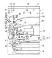
図1に本発明の一実施形態が採用される複写機の縦断面図を示す。
この複写機1は、本体10と、本体10の上部に開閉自在に装着された原稿押さえ11とを有している。
本体10には、その上部に位置して、原稿が載置される原稿台15が配置されている。本体10の内部には、正面から見て左側の端部で上下方向のほぼ中央に画像形成部16が設けられている。また、下部には、画像形成部16に用紙を供給するための給紙部17が設けられている。
【0014】
給紙部17には、本体10に着脱自在に取り付けられ、用紙を収納する給紙カセット18,19と、その上方に設けられるスタックバイパス20とを備えている。
原稿台15の下方には、原稿台15上に載置された原稿の画像情報を読み取るための光学系21が設けられている。光学系21は、原稿台15上に載置された原稿表面に光を照射するための光源22と、原稿表面から反射した光を偏向するためのミラー23,24,25と、ミラー25からの光を収束させるためのレンズ26と、レンズ26によって収束された光を受光して原稿画像に対応する画像データ信号を生成するCCDセンサなどの撮像素子27とを備えている。
【0015】
画像形成部16は、表面に静電潜像が形成される感光体ドラム30を有し、さらに感光体ドラム30の周囲に配置された主帯電装置31、現像装置32、転写ローラ33およびクリーニング装置34を有している。
主帯電装置31は、感光体ドラム30の表面を帯電させるための装置であり、感光体ドラム30の右斜め上方に配置されている。主帯電装置31から所定の間隙をあけて感光体ドラム30の右斜め下方に感光体ドラム30上にトナー像を形成する現像装置32が配置されている。現像装置32は、内部にトナーを収納し、感光体ドラム30に形成されている静電潜像をトナーによって顕像化するものである。また、転写ローラ33は、感光体ドラム30上のトナー像を用紙に転写するための装置であり、感光体ドラム30の左側方に配置されている。クリーニング装置34は、感光体ドラム30表面の残留トナーなどを除去するための装置であり、感光体ドラム30の上方に配置されている。
【0016】
感光体ドラム30の右側方には、感光体ドラム30の周面に静電潜像を形成するためのレーザユニット35が設けられている。レーザユニット35は、撮像素子27から得られる画像データ信号に基づいて感光体ドラム30周面に静電潜像を形成する。
給紙部17には、各給紙カセット18,19から画像形成部16方向に用紙を搬送するための縦搬送路41と、スタックバイパス20から画像形成部16方向に用紙を搬送するバイパス搬送路42とが設けられている。各給紙カセット18,19およびスタックバイパス20には、収納されている用紙を取り出すためのピックアップローラ43,44,45および用紙を1枚ずつ搬送路に送り出すための給紙ローラ対46,47,48が設けられている。縦搬送路41には、搬送ローラ対49,50が設けられており、バイパス搬送路42には搬送ローラ対51が設けられている。縦搬送路41とバイパス搬送路42は、感光体ドラム30と転写ローラ33とが対向する転写位置の下方で合流している。この合流した個所には、搬送されてくる用紙を所定位置に待機させるためのレジストローラ52が設けられている。
【0017】
感光体ドラム30および転写ローラ33の上方には、用紙上に転写されたトナーを溶融定着するための定着装置53が設けられている。定着装置53は、ヒータを内蔵する加熱ローラ54と加熱ローラ54に圧接する加圧ローラ55とが設けられており、両ローラ間に用紙を挟持して搬送するとともに、用紙表面に形成されたトナー画像を加熱定着するものである。
【0018】
定着装置53のさらに上方には、分岐部56が設けられている。
分岐部56の右側方には、排出ローラ対60を介して用紙が排出される排出トレイ57と、排出トレイ57の上方に配置され、排出ローラ対61を介して用紙が排出されるサブ排出トレイ58とが配置されている。また、分岐部56の左下方には両面コピーの際に用紙を反転させるためのスイッチバック部59が配置されている。分岐部56には、用紙搬送方向を排出トレイ57方向とスイッチバック部59方向とに切り換えるための分岐爪62が設けられている。分岐爪62の左側方には、2つの分岐爪63,64が設けられている。この2つの分岐爪63,64の下方にはスイッチバック部59に用紙を案内するスイッチバック搬送路65が設けられ、上方にはサブ排出トレイ58へ用紙を案内するサブトレイ搬送路66が設けられ、また、2つの分岐爪63,64の中間には図示しないソータやステープルソータなどのフィニッシャに用紙を搬送するフィニッシャ搬送路67が設けられている。分岐爪63,64は、搬送されてくる用紙をスイッチバック搬送路65、サブトレイ搬送路66またはフィニッシャ搬送路67のいずれかに案内するように切り換え可能となっている。
〔トナー搬送機構〕
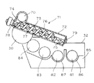
クリーニング装置34は、感光体ドラム30の周面に残留しているトナーを除去するものであって、感光体ドラム30の周面から除去したトナーは、トナー搬送装置を介して現像装置32に搬送される。このトナー搬送装置を図2を用いて説明する。
【0019】
クリーニング装置34には、感光体ドラム30の周面に残留しているトナーを掻き落とすために感光体ドラム30周面に圧接するクリーニングブレード(図示せず)と、クリーニングブレードによって掻き落とされたトナーを幅方向一端に搬送するスパイラル70とを備えている。
トナー搬送装置71は、クリーニング装置34の幅方向一端側に設けられている。トナー搬送装置71は、内部中空のチューブ形状のトナー搬送容器72と、トナー搬送容器72に回転可能に配置される搬送部材73とを備えている。
【0020】
トナー搬送容器72は、クリーニング装置34の幅方向一端側に連通する開口74と、現像装置32にトナーを排出する排出口75とを備えている。
搬送部材73は、回転軸76と、回転軸76の周囲に螺旋形状に設けられた当接部材77とで構成されている。当接部材77は、合成樹脂材料で構成される繊維を回転軸76の周囲に植設したブラシ状のものであり、トナー搬送容器72の内壁に当接するように設けられている。
【0021】
回転軸76は、トナー搬送容器72の長さ方向両端に設けられた軸受部78,79によって支持されており、図示しない駆動手段により回転駆動される。
クリーニングブレードにより感光体ドラム30の周面から掻き落とされた残留トナーは、スパイラル70によりトナー搬送装置71側に搬送され、開口74よりトナー搬送容器72内の搬送部材73上に落下する。
【0022】
ここで、搬送部材73は回転駆動されており、スパイラル70により搬送されてきたトナーは、搬送部材73の回転に伴ってトナー搬送容器72内を図右方向に搬送され、排出口75より現像装置32内に排出される。
このとき、搬送部材73の当接部材77は、弾性を有する合成樹脂材料によりブラシ状に形成されており、トナー搬送容器72の内壁を摺擦しながらトナーを搬送している。したがって、当接部材77の先端がトナー搬送容器72の内壁を常にクリーニングしており、トナー搬送容器72の内壁にトナーがこびりつくことがない。また、当接部材77は弾性を有するため、回転することによって常に弾性変形しており、この当接部材77の表面にトナーが付着し難く、トナーが付着しても弾性変形することによって簡単に離脱して、付着したトナーが大きなかたまりとなってトナー搬送容器72内を閉塞することがなくなる。したがって、トナー搬送装置71のトナー搬送能力が低下することを防止することができる。〔現像装置〕
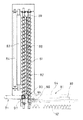
現像装置32は、図2、図3に示すようなケーシング85を有している。このケーシング85内には、2つのスパイラル81,82と、攪拌パドル83と、現像ローラ84とが設けられている。
【0023】
ケーシング85には、スパイラル81,82が配置される溝部86,87が形成されている。この溝部86,87は、スパイラル81,82によってキャリアとトナーとが攪拌されるとともに搬送される搬送経路を構成している。溝部86では、スパイラル81が回転駆動されることによって、図3下から上方に向けてキャリアおよびトナーが搬送される。また、溝部87では、スパイラル82が回転駆動されることによって、図3上から下方に向けてキャリアおよびトナーが搬送される。溝部86および溝部87の間には、両搬送経路を隔離するための隔壁88が形成されている。この隔壁88は、長さ方向両端部において切欠部89,90を有しており、この切欠部89,90によって溝部86および溝部87が結合されている。このことから、スパイラル81,82によって搬送されるキャリアおよびトナーは、溝部86および溝部87に沿って攪拌されながら循環することとなる。
【0024】
現像装置32には、内部にトナーを収納し現像装置32にトナーを補給するためのトナーカートリッジ91が着脱自在となっている。トナーカートリッジ91は、内部にスパイラル92や攪拌パドル93などを内蔵するケーシング94を有している。ケーシング94には、トナーを排出するためのトナー排出口95が設けられている。
【0025】
現像装置32のケーシング85には、トナーカートリッジ91のトナー排出口95に対応する位置にトナー補給口96が設けられている。このトナー補給口96は、スパイラル81が配置されている溝部86の上方に設けられている。
また、現像装置32のケーシング85には、トナー搬送装置71の排出口75に対応する位置に回収トナー補給口97が設けられている。この回収トナー補給口97は、スパイラル82が配置されている溝部87の上方であって切欠部90の近傍に設けられている。
【0026】
このことにより、トナー搬送装置71によって搬送されてきた回収トナーは、回収トナー補給口97を介して、スパイラル82上に落下する。この回収トナーが落下する位置は、スパイラル82の図3下端位置である。スパイラル82の搬送方向は、図3上から下方に向けてであるため、スパイラル82上に落下した回収トナーは、すぐに切欠部90を介してスパイラル81が配置されている溝部86に搬送される。
【0027】
ここで、トナー補給口96を介してトナーカートリッジ91から補給されるトナーと混合されて、スパイラル81によりキャリアと攪拌されるとともに、図3下から上方に向けて搬送される。スパイラル81により上方まで搬送されたキャリアおよびトナーは、切欠部89を介して溝部87に搬送され、スパイラル82によってさらに攪拌されるとともに溝部87内を搬送されることとなる。
【0028】
溝部87を搬送されるキャリアおよびトナーの一部は、攪拌パドル83側に溢れ、攪拌パドル83によって現像ローラ84側に搬送される。現像ローラ84に付着したトナーにより、感光体ドラム30周面に形成された静電潜像がトナー画像に顕像化されることとなる。
以上から、クリーニング装置34によって回収された回収トナーは、現像装置32に直接搬送されてリサイクルされるため、資源を有効に活用することが可能である。また、現像装置32内には、2つのスパイラル81,82が配置されており、クリーニング装置34から回収されてきた回収トナーをこのスパイラル上に落下させることとで、キャリアとトナーとの混合を好適に行うことができる。特に、スパイラル81,82によって形成されるキャリアおよびトナーの搬送経路のうち、トナーカートリッジ91から新しいトナーを補給する補給口96よりも上流側に回収トナー補給口97を設けているため、各スパイラル81,82によってキャリア、回収トナーおよび新しいトナーを十分に攪拌することができ、画質の低下を招くことがなくなる。
〔トナー補給部〕
トナーカートリッジ91は、排出口94が現像装置32のトナー補給口96に重合するセット位置(図3)と、図3においてセット位置から右方に位置する待避位置との間で移動可能となっており、図示しないガイド部材によってスライド移動するように構成されている。
【0029】
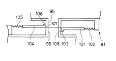
図4に示すように、トナーカートリッジ91にはスライド移動可能な第1スライド板101が取り付けられており、バネ102によって排出口95を遮蔽する方向に付勢されている。第1スライド板101の右端部分は、現像装置32の一部に当接可能な作動突片103を構成している。
また、現像装置32のトナー補給口96付近には、スライド移動可能な第2スライド板104が取り付けられており、バネ105によってトナー補給口96を遮蔽する方向に付勢されている。第2スライド板104の左端部分は、トナーカートリッジ91の一部に当接可能な作動突片106を構成している。
【0030】
トナーカートリッジ91の排出口95の左側外表面は、第2スライド板104の作動突片106に当接して第2スライド板104をスライド移動させる位置規制部107を構成している。また、現像装置32のトナー補給口96の右側外表面は、第1スライド板101の作動突片103に当接して第1スライド板101をスライド移動させる位置規制部108を構成している。
【0031】
トナーカートリッジ91がセット位置にセットされていない場合には、図4に示すように、第1スライド板101は、バネ102により図左方向に付勢されて排出口95を遮蔽している。また、第2スライド板104も、バネ105により図右方向に付勢されてトナー補給口96を遮蔽している。
トナーカートリッジ91を図左方向にスライド移動させてセット位置にセットすると、図5に示すように、第1スライド板101の作動突片103が現像装置32の位置規制部108に当接し、バネ102の付勢力に抗して図右方向に移動し、トナーカートリッジ91の排出口95を開放状態とする。同時に、第2スライド板104の作動突片106がトナーカートリッジ91の位置規制部107に当接し、バネ105の付勢力に抗して図左方向に移動し、現像装置32のトナー補給口96を開放状態とする。このことにより、トナーカートリッジ91の排出口95と現像装置32のトナー補給口96とが連通状態となり、トナーカートリッジ91から現像装置32へのトナー補給が可能となる。
【0032】
トナーカートリッジ91の交換もしくは他の処理を行うために待避位置に移動させる場合には、トナーカートリッジ91を図5の状態から図右方向に移動させる。このとき、第1スライド板101は、位置規制部108の規制から開放されて、バネ102に付勢力により図左方向に移動し、トナーカートリッジ91の排出口95を遮蔽する。同時に、第2スライド板104は、位置規制部107の規制から開放されて、バネ105の付勢力により図右方向に移動し、現像装置32のトナー補給口96を遮蔽する。
【0033】
このことにより、トナーカートリッジ91を所定のセット位置から移動させる場合に、トナーカートリッジ91の排出口95は第1スライド板103によって遮蔽され、現像装置32のトナー補給口96は第2スライド板104によって遮蔽されるため、トナーが外部に飛散することを防止できる。特に、メンテナンス作業を行う場合には、トナーカートリッジ91内部に多くのトナーが残っている場合があり、トナーカートリッジ91を待避位置に移動させてもこの残存しているトナーが外部に飛散することを防止できる。
【0034】
第1スライド板101の作動突片103に当接する位置規制部材を別途現像装置32に設けることも可能であり、第2スライド板104の作動突片106に当接する位置規制部材を別途トナーカートリッジ91に設けることも可能である。また、トナーカートリッジ91が現像装置32に直接取り付けられる場合を例示したが、現像装置にトナーを供給するためのトナーホッパーを備え、このトナーホッパーに対してトナーカートリッジが着脱自在となっている装置であっても、同様の構成とすることが可能である。
〔イメージングユニット〕
図6に示すように、感光体ドラム30、主帯電装置31、現像装置32、クリーニング装置34およびトナー搬送装置71は、ケーシング111内に一体的に収納されたイメージングユニット110を構成している。ケーシング111の下面は、複写機1の内部に収納されている状態で水平面となる底面112を有している。底面112には、図6紙面に垂直方向に被案内溝113,114が設けられている。複写機1側には、図6紙面に垂直な方向に延設されるガイド部材115,116が形成されている。イメージングユニット110の被案内溝113,114はそれぞれガイド部材115,116に嵌合しており、イメージングユニット110が図6紙面に垂直な方向に移動可能となっている。
【0035】
また、イメージングユニット110は、ガイド部材115,116に案内されて複写機1の前面(図6紙面に鉛直上方)に引き出すことが可能となっている。複写機1から引き出されたイメージングユニット110は、ケーシング111の底面112を利用して、水平面に載置可能である。このことにより、イメージングユニット110は、複写機1から引き出された際に、複写機1内に収納されている状態を維持しつつ水平面上に載置することが可能であり、内部に収納された現像材やトナーを安定的に保つことができる。また、外部に露出した感光体ドラム30の周面を損傷することがない。さらに、下方やその他外方に突出する部品を特に設ける必要がないため、イメージングユニット110の着脱作業を容易にするとともに、他の部品や作業者を傷つけることがない。
〔制御部〕
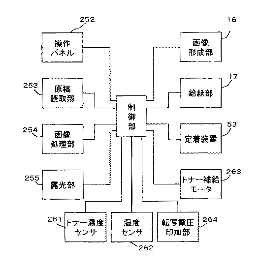
複写機1の内部には、図7に示すように、制御部251が設けられている。制御部251は、CPU,RAM,ROM,各種ドライバなどを含むマイクロコンピュータシステムで構成されている。制御部251には、各種操作指示をおこなうための操作パネル252が接続されている。操作パネル252は、テンキーやその他指令キーを含む入力キー部および液晶表示素子やLEDなどで構成される表示部などを含んでおり、複写動作の開始を指示するためのスタートキーなども含まれている。
【0036】
制御部251には、さらに、画像読取部253が接続されている。画像読取部253は、前述した光学系21などを含み、原稿台15上に載置された原稿に光を照射して、原稿から反射する光を撮像素子27で読み取って画像データ信号に変換する。また、制御部251には、撮像素子27から出力される画像データ信号を受け取って画像処理を行う画像処理部254が接続されている。
【0037】
制御部251には、レーザユニット35を含む露光部255が接続されている。露光部255では、画像処理部254によって処理される画像情報に基づいて、レーザユニット35からレーザ光を照射し、感光体ドラム30周面に静電潜像を形成する。
さらに、制御部251には、感光体ドラム30、現像装置32、転写ローラ33などを含む画像形成部16、画像形成部16に用紙を搬送する給紙部17、画像形成部16で用紙表面に転写されたトナー画像を加熱して溶融定着する定着装置53が接続されている。 また、現像装置32内に設けられ、現像装置32に収納されている現像材のT/Dを検出するためのトナー濃度センサ261が制御部251に接続されている。さらに、装置内の絶対湿度を検出するための湿度センサ262が制御部251に接続されている。また、トナーカートリッジ91から現像装置32内にトナーを補給するためのトナー補給モータ263が制御部251に接続されている。さらに、転写ローラ33に転写電圧を印加するための転写電圧印加部264が制御部251に接続されている。
【0038】
トナーカートリッジ91は、図3に示すように、内部に収納されているトナーを攪拌するための攪拌パドル93が回転自在に設けられている。攪拌パドル93の回転軸は、排出口95の上方に延設されており、回転軸の回転に伴って図右から左方向にトナーを搬送するスパイラル(図示せず)が排出口95の近傍に設けられている。トナー補給モータ263は、この攪拌パドル93の回転軸を回転駆動するように構成されており、トナー補給モータ263の駆動時間に応じて、トナーカートリッジ91から現像装置32にトナーが補給されるように構成されている。
【0039】
制御部251では、トナー濃度センサ261の出力信号に基づく現像装置32内の現像材のT/Dにより、トナー補給モータ263に供給する駆動信号のON/OFFデューティ比を決定し、現像装置32内のT/Dが所定の目標T/D値となるように、トナーカートリッジ91からのトナー補給量を調整する。
また、制御部251では、転写電圧印加部264を介して転写ローラ33に所定の転写電圧値を印加して、感光体ドラム30から用紙上への画像転写を行う。
【0040】
制御部251は、湿度センサ262によって検出された装置内の絶対湿度に基づいて、目標T/D値の補正を行う。また、同時に転写電圧印加部264による転写電圧値の補正を行う。
【0041】
【表1】
例えば、表1に示すように、温度20℃/湿度45%の通常の環境下で、現像装置32内の目標T/D値を4.5%とするためのトナー濃度センサ261のしきい値が3.0Vであるとする。このときの転写電圧印加部264による転写電圧値を5kVとする。この状態から温度20℃/湿度85%になった場合に、現像装置32内のT/D値が同じであってもトナー濃度センサ261の出力が4.0Vとなる。このトナー濃度センサ261の湿度に対する出力の変動に伴って、目標T/D値は5.5%程度に変動してしまう。したがって、制御部251では、目標T/D値を下げるように制御する。湿度が上昇しているため、通常の環境下での目標T/D値である4.5%に設定しても、トナーの飛散のおそれがあり、ここでは4.5%よりも低く設定することが好ましく、例えば、4.0%に設定することとする。このことにより、適切な画像濃度を得ることが困難となるが、転写ローラ33に印加する転写電圧を高めることで、十分な画像濃度を得られることとなる。この場合には、表1に示すように、転写電圧値を5.5kVに設定する。
【0043】
このように設定することにより、用紙上に形成される画像濃度が、装置内の絶対湿度に影響されることなく、例えば、湿度が上昇した場合であっても、トナーの飛散やかぶりの発生、また濃度むらの発生などを防止することができる。
絶対湿度に対応して転写電圧値を補正することに代えて、主帯電装置31の印加電圧を絶対湿度に対応して変更し、感光体ドラム30の表面電位を補正することによって、同様の効果を得ることができる。
【0044】
【発明の効果】
本発明によれば、装置内の絶対湿度に基づいて、目標T/D値を補正するとともに、転写装置に印加する印加電圧値を補正することによって、形成される画像濃度を適切に維持し、トナーの飛散やかぶりの発生、濃度むらの発生などを防止することができる。
【図面の簡単な説明】
【図1】本発明の1実施形態を採用した複写機の縦断面概略図。
【図2】要部説明図。
【図3】要部説明図。
【図4】トナー補給部の動作を示す説明図。
【図5】トナー補給部の動作を示す説明図。
【図6】イメージングユニットの縦断面図。
【図7】制御ブロック図。
【符号の説明】
1 複写機
30 感光体ドラム
31 主帯電装置
32 現像装置
33 転写ローラ
34 クリーニング装置
251 制御部
252 操作パネル
253 画像読取部
254 画像処理部
255 露光部
261 トナー濃度センサ
262 湿度センサ
263 トナー補給モータ
264 転写電圧印加部[0001]
BACKGROUND OF THE INVENTION
The present invention relates to an image forming apparatus, in particular, an electrostatic latent image formed on a peripheral surface of a photosensitive drum is visualized as a toner image by a developing device, and a photosensitive member is applied from the back side of a sheet by a transfer device to which a high voltage is applied. The present invention relates to an image forming apparatus that attracts and transfers a toner image on a drum to a sheet.
[0002]
[Prior art]
In an image forming apparatus such as a copying machine, a printer, or a facsimile machine, an original is placed on an original table provided on the upper surface of the apparatus, and the original image is irradiated with light, and the original image is based on light reflected from the original. Read. Based on the read original image, an electrostatic latent image is formed on the surface of the photosensitive drum. The photosensitive drum is charged to a predetermined polarity by the main charging device, and when light is irradiated based on the original image, the charge in that portion is removed to form an electrostatic latent image.
[0003]
Around the photosensitive drum, a developing device, a transfer device, a separation device, a cleaning device, and the like are arranged.
The developing device stores therein toner charged to the same polarity as the photosensitive drum. The toner stored in the developing device is adsorbed to a portion of the photosensitive drum where there is no charge at a position close to the developing device and the photosensitive drum. Therefore, the electrostatic latent image formed on the peripheral surface of the photosensitive drum is visualized as a toner image.
[0004]
The transfer device applies a voltage having a polarity opposite to that of the toner from the back surface of the sheet conveyed to the photosensitive drum, and attracts the toner on the circumferential surface of the photosensitive drum onto the sheet to generate a toner image. Transcript.
A separation device is disposed on the downstream side of the transfer device in the sheet conveyance direction. This separating device sucks the sheet from the back side so that the sheet does not wind around the photosensitive drum, and employs, for example, a separating needle to which a predetermined voltage is applied.
[0005]
The cleaning device is for removing the toner remaining on the circumferential surface of the photosensitive drum. The cleaning blade abuts on the circumferential surface of the photosensitive drum and scrapes off the toner, and the binding force of the toner on the circumferential surface of the photosensitive drum. A fur brush for weakening, a toner conveying device for conveying the toner peeled off from the peripheral surface of the photosensitive drum to a collecting unit, and the like are provided.
[0006]
[Problems to be solved by the invention]
In an image forming apparatus using a two-component toner, a developing material including a carrier and toner is accommodated in the developing device. When the electrostatic latent image on the peripheral surface of the photosensitive drum is visualized, only the toner in the developing device moves to the peripheral surface of the photosensitive drum, and the carrier remains in the developing device. A magnetic sensor is provided in the developing device, and the magnetic permeability of the contents stored by the magnetic sensor is detected to detect the toner concentration with respect to the developer, so-called T / D, so that the consumed toner is detected. The amount is determined.
[0007]
The developing device can be replenished with toner via a toner cartridge or a toner hopper so that the T / D value in the developing device becomes a predetermined target T / D value based on the detection result of the magnetic sensor. The toner is replenished.
When the humidity in the apparatus becomes high, the charge amount of the carrier in the developing apparatus becomes low and the toner is likely to be scattered. As a result, the toner is easily transferred from the developing device to the peripheral surface of the photosensitive drum, and the density of the formed image tends to increase. Further, when the humidity increases, the output of the magnetic sensor built in the developing device is detected to be higher than the actual value, and the T / D value obtained based on the detection signal of such a magnetic sensor is lower than the actual value. End up. For this reason, control is performed such that toner is further replenished into the developing device from a toner cartridge or a toner hopper, and the density of the formed image is further increased.
[0008]
For this reason, a humidity sensor for detecting the absolute humidity in the image forming apparatus may be provided, and the target T / D value may be lowered when the humidity increases based on the detection result of the humidity sensor. It is done. In this case, since the T / D value in the developing device decreases as the humidity in the image forming apparatus increases, toner scattering can be suppressed.
[0009]
However, if the T / D in the developing device is lowered in the above case, there is a possibility that an appropriate image density cannot be maintained. This is because the charge amount of the carrier is lowered and the toner concentration is lowered due to the increase in humidity, and the ratio of the toner to the carrier is reduced, so that the uniform toner concentration cannot be maintained and the toner is formed. This is thought to be due to uneven density in the image.
[0010]
An object of the present invention is to suppress fluctuations in image density due to fluctuations in humidity in the apparatus, for example, to prevent toner scattering and fogging when the humidity becomes high.
[0011]
[Means for Solving the Problems]
An image forming apparatus according to the present invention includes a photosensitive drum, a developing device, a cleaning device, a toner conveying device, a transfer device, a toner concentration detecting unit, a toner replenishing unit, a transfer voltage applying unit, and humidity detection. Means and image density control means. An electrostatic latent image is formed on the circumferential surface of the photosensitive drum. Development device, Containing a developer composed of carrier and toner,The electrostatic latent image on the photosensitive drum is visualized as a toner image. The cleaning device removes toner remaining on the peripheral surface of the photosensitive drum. The toner conveying device conveys the toner removed by the cleaning device to the developing device. The transfer device is marked with high voltage.AdditionThen, the toner image on the photosensitive drum is attracted from the back side of the paper and transferred to the paper. The toner concentration detecting means measures the toner concentration with respect to the developer in the developing device. The toner replenishing unit replenishes the toner based on the detection result of the toner concentration detecting unit so that the toner concentration in the developing device becomes the target T / D value. The transfer voltage applying unit applies a voltage to the transfer device. The humidity detecting means detects absolute humidity in the apparatus.The image density control unit sets a new T / D value that is lower than the target T / D value until an appropriate image density cannot be obtained as the absolute humidity detected by the humidity detection unit increases. The voltage applied to the transfer device by the transfer voltage applying means is set high.
[0012]
thisAs a result, even when the target T / D value of the toner replenishing unit is corrected in accordance with the absolute humidity detected by the humidity detecting unit, even when an appropriate image density cannot be obtained, the transfer voltage value is corrected. Thus, the image density transferred onto the paper can be made appropriate, and problems such as toner scattering, fogging, and density unevenness can be eliminated.
[0013]
DETAILED DESCRIPTION OF THE INVENTION
FIG. 1 is a longitudinal sectional view of a copying machine in which an embodiment of the present invention is adopted.
The copying machine 1 includes a
The
[0014]
The
An
[0015]
The
The
[0016]
A
The
[0017]
Above the
[0018]
A
Disposed on the right side of the
[Toner transport mechanism]
The
[0019]
The
The
[0020]
The
The
[0021]
The
The residual toner scraped off from the peripheral surface of the
[0022]
Here, the
At this time, the abutting
The developing
[0023]
In the
[0024]
In the developing
[0025]
The
A recovery
[0026]
As a result, the collected toner conveyed by the
[0027]
Here, the toner is mixed with the toner replenished from the
[0028]
A part of the carrier and the toner conveyed through the
As described above, since the collected toner collected by the
[Toner Supply Section]
The
[0029]
As shown in FIG. 4, a
Further, a
[0030]
The left outer surface of the
[0031]
When the
When the
[0032]
When the
[0033]
Thus, when the
[0034]
A position restricting member that abuts against the operating
[Imaging unit]
As shown in FIG. 6, the
[0035]
Further, the
(Control part)
As shown in FIG. 7, a control unit 251 is provided inside the copying machine 1. The control unit 251 is configured by a microcomputer system including a CPU, RAM, ROM, various drivers, and the like. An
[0036]
An
[0037]
An
Further, the control unit 251 includes an
[0038]
As shown in FIG. 3, the
[0039]
The control unit 251 determines the ON / OFF duty ratio of the drive signal supplied to the
Further, the control unit 251 applies a predetermined transfer voltage value to the transfer roller 33 via the transfer
[0040]
The control unit 251 corrects the target T / D value based on the absolute humidity in the apparatus detected by the
[0041]
[Table 1]
For example, as shown in Table 1, the threshold value of the
[0043]
By setting in this way, the image density formed on the paper is not affected by the absolute humidity in the apparatus. For example, even when the humidity is increased, toner scattering and fogging occur, Moreover, the occurrence of uneven density can be prevented.
Instead of correcting the transfer voltage value corresponding to the absolute humidity, the applied voltage of the
[0044]
【The invention's effect】
According to the present invention, by correcting the target T / D value based on the absolute humidity in the apparatus and correcting the applied voltage value applied to the transfer apparatus, the formed image density is appropriately maintained, It is possible to prevent toner scattering, fogging, and density unevenness.
[Brief description of the drawings]
FIG. 1 is a schematic vertical sectional view of a copying machine that employs an embodiment of the present invention.
FIG. 2 is an explanatory diagram of a main part.
FIG. 3 is an explanatory diagram of a main part.
FIG. 4 is an explanatory diagram illustrating an operation of a toner supply unit.
FIG. 5 is an explanatory diagram illustrating an operation of a toner replenishing unit.
FIG. 6 is a longitudinal sectional view of an imaging unit.
FIG. 7 is a control block diagram.
[Explanation of symbols]
1 Copying machine
30 Photosensitive drum
31 Main charging device
32 Developer
33 Transfer roller
34 Cleaning device
251 Control unit
252 Operation panel
253 Image reading unit
254 Image processing unit
255 Exposure section
261 Toner density sensor
262 Humidity sensor
263 Toner supply motor
H.264 Transfer voltage application unit
Claims (1)
キャリア及びトナーからなる現像材が収容され、前記感光体ドラム上の静電潜像をトナー画像に顕像化する現像装置と、
前記感光体ドラムの周面に残留しているトナーを除去するクリーニング装置と、
前記クリーニング装置によって除去されたトナーを前記現像装置に搬送するトナー搬送装置と、
高電圧が印加され、用紙の裏面側から前記感光体ドラム上のトナー画像を引きつけて用紙に転写する転写装置と、
前記現像装置内における現像材に対するトナー濃度を測定するトナー濃度検出手段と、
前記トナー濃度検出手段の検出結果に基づいて前記現像装置内のトナー濃度が目標T/D値になるようにトナーを補給するトナー補給手段と、
前記転写装置に電圧を印加する転写電圧印加手段と、
装置内の絶対湿度を検出する湿度検出手段と、
前記湿度検出手段の検出する絶対湿度の上昇に伴って、前記適切な画像濃度が得られなくなるまで前記目標T/D値よりも低くしたT/D値を新たな目標T/D値として設定し、前記転写電圧印加手段による転写装置に対する印加電圧値を高く設定する画像濃度制御手段と、
を備えた画像形成装置。A photosensitive drum on which an electrostatic latent image is formed on the peripheral surface;
A developing device that contains a developer composed of a carrier and toner, and visualizes the electrostatic latent image on the photosensitive drum into a toner image;
A cleaning device for removing toner remaining on the peripheral surface of the photosensitive drum;
A toner conveying device for conveying the toner removed by the cleaning device to the developing device;
A high voltage is marked pressurized, a transfer device for transferring the sheet from the back side of the paper to attract the toner image on the photosensitive drum,
Toner density detecting means for measuring the toner density with respect to the developer in the developing device;
Toner replenishing means for replenishing toner based on the detection result of the toner density detecting means so that the toner density in the developing device becomes a target T / D value;
Transfer voltage applying means for applying a voltage to the transfer device;
Humidity detecting means for detecting the absolute humidity in the device;
A T / D value that is lower than the target T / D value is set as a new target T / D value until the appropriate image density is not obtained as the absolute humidity detected by the humidity detecting means increases. Image density control means for setting a high applied voltage value to the transfer device by the transfer voltage application means;
An image forming apparatus.
Priority Applications (1)
| Application Number | Priority Date | Filing Date | Title |
|---|---|---|---|
| JP21223898A JP3926041B2 (en) | 1998-07-28 | 1998-07-28 | Image forming apparatus |
Applications Claiming Priority (1)
| Application Number | Priority Date | Filing Date | Title |
|---|---|---|---|
| JP21223898A JP3926041B2 (en) | 1998-07-28 | 1998-07-28 | Image forming apparatus |
Publications (2)
| Publication Number | Publication Date |
|---|---|
| JP2000047438A JP2000047438A (en) | 2000-02-18 |
| JP3926041B2 true JP3926041B2 (en) | 2007-06-06 |
Family
ID=16619266
Family Applications (1)
| Application Number | Title | Priority Date | Filing Date |
|---|---|---|---|
| JP21223898A Expired - Fee Related JP3926041B2 (en) | 1998-07-28 | 1998-07-28 | Image forming apparatus |
Country Status (1)
| Country | Link |
|---|---|
| JP (1) | JP3926041B2 (en) |
Cited By (1)
| Publication number | Priority date | Publication date | Assignee | Title |
|---|---|---|---|---|
| US9550971B2 (en) | 2009-04-14 | 2017-01-24 | Therapeutic Proteins International, LLC | Universal bioreactors and methods of use |
Families Citing this family (2)
| Publication number | Priority date | Publication date | Assignee | Title |
|---|---|---|---|---|
| JP5247223B2 (en) * | 2008-05-02 | 2013-07-24 | キヤノン株式会社 | Image forming apparatus |
| JP7555778B2 (en) | 2020-10-13 | 2024-09-25 | キヤノン株式会社 | Image forming device |
-
1998
- 1998-07-28 JP JP21223898A patent/JP3926041B2/en not_active Expired - Fee Related
Cited By (1)
| Publication number | Priority date | Publication date | Assignee | Title |
|---|---|---|---|---|
| US9550971B2 (en) | 2009-04-14 | 2017-01-24 | Therapeutic Proteins International, LLC | Universal bioreactors and methods of use |
Also Published As
| Publication number | Publication date |
|---|---|
| JP2000047438A (en) | 2000-02-18 |
Similar Documents
| Publication | Publication Date | Title |
|---|---|---|
| JP3581720B2 (en) | Developing device | |
| JP6788972B2 (en) | Develop equipment and image forming equipment | |
| US7715762B2 (en) | Developing apparatus and image forming apparatus including same | |
| JP2001249545A (en) | Image forming device | |
| JP6440017B2 (en) | Developing device and image forming apparatus | |
| JP5240557B2 (en) | Developing device, image forming apparatus, and process cartridge | |
| JP4487618B2 (en) | Image forming apparatus | |
| JP2000029309A (en) | Shutter mechanism for image forming device | |
| JP3926041B2 (en) | Image forming apparatus | |
| CN112540519B (en) | Printing device | |
| US7369796B2 (en) | Developer apparatus, image forming apparatus and toner supplying method | |
| JP5037254B2 (en) | Developing device, image forming apparatus | |
| JP2000029302A (en) | Toner concentration controller image forming device | |
| JP2008015262A (en) | Developing device | |
| JP5448767B2 (en) | Image forming apparatus | |
| JPH09236978A (en) | Image forming apparatus and developer supply method for the image forming apparatus | |
| JP2000089643A (en) | Imaging unit of image forming device | |
| JP7154268B2 (en) | Developing device and image forming device | |
| JPS6385661A (en) | Developer concentration adjusting device for image forming device | |
| JP2011027904A (en) | Toner recycle system, process cartridge including the same, and image forming apparatus | |
| JP4990723B2 (en) | Developing device and image forming apparatus | |
| JP2000029312A (en) | Developing device for image forming device | |
| JP7127307B2 (en) | Developing device, process cartridge, and image forming apparatus | |
| JP5412852B2 (en) | Image forming device toner recycling mechanism | |
| JP2025184005A (en) | Image forming apparatus |
Legal Events
| Date | Code | Title | Description |
|---|---|---|---|
| A521 | Written amendment |
Free format text: JAPANESE INTERMEDIATE CODE: A523 Effective date: 20040105 |
|
| A02 | Decision of refusal |
Free format text: JAPANESE INTERMEDIATE CODE: A02 Effective date: 20040127 |
|
| A521 | Written amendment |
Free format text: JAPANESE INTERMEDIATE CODE: A523 Effective date: 20040329 |
|
| A911 | Transfer of reconsideration by examiner before appeal (zenchi) |
Free format text: JAPANESE INTERMEDIATE CODE: A911 Effective date: 20040519 |
|
| A912 | Removal of reconsideration by examiner before appeal (zenchi) |
Free format text: JAPANESE INTERMEDIATE CODE: A912 Effective date: 20040611 |
|
| A521 | Written amendment |
Free format text: JAPANESE INTERMEDIATE CODE: A523 Effective date: 20061204 |
|
| A61 | First payment of annual fees (during grant procedure) |
Free format text: JAPANESE INTERMEDIATE CODE: A61 Effective date: 20070227 |
|
| R150 | Certificate of patent or registration of utility model |
Free format text: JAPANESE INTERMEDIATE CODE: R150 |
|
| FPAY | Renewal fee payment (event date is renewal date of database) |
Free format text: PAYMENT UNTIL: 20100309 Year of fee payment: 3 |
|
| FPAY | Renewal fee payment (event date is renewal date of database) |
Free format text: PAYMENT UNTIL: 20110309 Year of fee payment: 4 |
|
| FPAY | Renewal fee payment (event date is renewal date of database) |
Free format text: PAYMENT UNTIL: 20120309 Year of fee payment: 5 |
|
| FPAY | Renewal fee payment (event date is renewal date of database) |
Free format text: PAYMENT UNTIL: 20130309 Year of fee payment: 6 |
|
| FPAY | Renewal fee payment (event date is renewal date of database) |
Free format text: PAYMENT UNTIL: 20130309 Year of fee payment: 6 |
|
| S533 | Written request for registration of change of name |
Free format text: JAPANESE INTERMEDIATE CODE: R313533 |
|
| FPAY | Renewal fee payment (event date is renewal date of database) |
Free format text: PAYMENT UNTIL: 20130309 Year of fee payment: 6 |
|
| R350 | Written notification of registration of transfer |
Free format text: JAPANESE INTERMEDIATE CODE: R350 |
|
| FPAY | Renewal fee payment (event date is renewal date of database) |
Free format text: PAYMENT UNTIL: 20130309 Year of fee payment: 6 |
|
| LAPS | Cancellation because of no payment of annual fees |