JP3919085B2 - Magnetic disk cartridge - Google Patents
Magnetic disk cartridge Download PDFInfo
- Publication number
- JP3919085B2 JP3919085B2 JP2002080060A JP2002080060A JP3919085B2 JP 3919085 B2 JP3919085 B2 JP 3919085B2 JP 2002080060 A JP2002080060 A JP 2002080060A JP 2002080060 A JP2002080060 A JP 2002080060A JP 3919085 B2 JP3919085 B2 JP 3919085B2
- Authority
- JP
- Japan
- Prior art keywords
- magnetic disk
- shutter
- housing
- disk cartridge
- lower shell
- Prior art date
- Legal status (The legal status is an assumption and is not a legal conclusion. Google has not performed a legal analysis and makes no representation as to the accuracy of the status listed.)
- Expired - Fee Related
Links
Images


Classifications
-
- G—PHYSICS
- G11—INFORMATION STORAGE
- G11B—INFORMATION STORAGE BASED ON RELATIVE MOVEMENT BETWEEN RECORD CARRIER AND TRANSDUCER
- G11B23/00—Record carriers not specific to the method of recording or reproducing; Accessories, e.g. containers, specially adapted for co-operation with the recording or reproducing apparatus ; Intermediate mediums; Apparatus or processes specially adapted for their manufacture
- G11B23/02—Containers; Storing means both adapted to cooperate with the recording or reproducing means
- G11B23/03—Containers for flat record carriers
- G11B23/0326—Assembling of containers
-
- G—PHYSICS
- G11—INFORMATION STORAGE
- G11B—INFORMATION STORAGE BASED ON RELATIVE MOVEMENT BETWEEN RECORD CARRIER AND TRANSDUCER
- G11B23/00—Record carriers not specific to the method of recording or reproducing; Accessories, e.g. containers, specially adapted for co-operation with the recording or reproducing apparatus ; Intermediate mediums; Apparatus or processes specially adapted for their manufacture
- G11B23/02—Containers; Storing means both adapted to cooperate with the recording or reproducing means
- G11B23/03—Containers for flat record carriers
- G11B23/0301—Details
- G11B23/0308—Shutters
-
- G—PHYSICS
- G11—INFORMATION STORAGE
- G11B—INFORMATION STORAGE BASED ON RELATIVE MOVEMENT BETWEEN RECORD CARRIER AND TRANSDUCER
- G11B23/00—Record carriers not specific to the method of recording or reproducing; Accessories, e.g. containers, specially adapted for co-operation with the recording or reproducing apparatus ; Intermediate mediums; Apparatus or processes specially adapted for their manufacture
- G11B23/02—Containers; Storing means both adapted to cooperate with the recording or reproducing means
- G11B23/03—Containers for flat record carriers
- G11B23/0301—Details
- G11B23/0313—Container cases
- G11B23/0316—Constructional details, e.g. shape
Landscapes
- Magnetic Record Carriers (AREA)
- Feeding And Guiding Record Carriers (AREA)
Description
【0001】
【発明の属する技術分野】
本発明は、デジタルスチルカメラ、デジタルビデオカメラ、ノートパソコン等に設けられたディスクドライブ等に対し交換自在に装填可能な小型の磁気ディスクカートリッジに関するものである。
【0002】
【従来の技術】
従来、デジタルスチルカメラ、デジタルビデオカメラ、ノートパソコン等の電子機器のカードスロットには、種々の記録メディアが挿抜可能に装填され、記録再生をするようになっている。このような記録媒体としては、半導体メモリタイプのもの、ハードディスク型のもの、光ディスク型のもの、フロッピー(登録商標)ディスクのような磁気ディスクの小型のもの等、各種のものが実用に供されている。
【0003】
【発明が解決しようとする課題】
この中では、半導体のメモリが取り扱いやすく、記録容量も適当に大きいので、最もポピュラーであるが、比較的価格が高い。したがって、これらのメモリを用いるデジタルカメラなどでは、撮影した画像データをパソコンなどに転送して保存し、その後データは削除し、記録媒体は繰返し使うのが一般的である。
【0004】
ハードディスク型のものとしては、340MBや1GBの容量を持つものが知られているが、これも価格が高く、データは他に転送して保存し、記録媒体は繰返し使うことになる。
【0005】
光ディスク型のものは大きさの割に記録容量が大きく、例えば35mm×41mm×11mmのサイズの中に256MBのデータを記録することができ、512MBの記録容量を持ったものも実現しようとしている。しかし、光ディスクは書込みに時間がかかるので記録速度が遅いという難点がある。
【0006】
一方、フロッピー(登録商標)ディスクのような磁気ディスクを50mm×55mm×2mm程度の小型のものとし、これをパソコン等のカードスロットに挿入できるサイズのディスクドライブに交換自在に装填可能としたものも知られているが、これは容量が40MBと小さく、カメラの画像を記録するという観点では容量不足であるし、大きさもデジタルカメラには向かない。
【0007】
近年、デジタルカメラが、その記録の簡便さ、撮像素子の開発による画質の向上、データの削除や転送の可能性や記録容量の大きさなど、パソコンが普及した社会の背景と相俟って、急速に広く普及しているが、記録媒体(以下、メディアという)が上述のように価格や容量の面で制限されているため、その使用の態様に制限がある。例えば、メディアが高価であるため、1台のカメラにメディアを何枚も持つということはしないで、データが一杯になったらパソコンに移して削除するなどして、1枚のメディアを繰返し使用するのが普通であることは上述の通りである。そのため、旅先で記録媒体が足りなくなることがあり、またデータを入れたメディアをそのまま保存したり、人にあげたりするというようなことができない。
【0008】
そこで、デジタルカメラで撮影したデータをそのまま保存したり、気軽に人にあげたりすることができるように、大容量で安価な小型のメディアの実現が望まれる。また、パソコンにおいても、データを入れて人に渡したりすることができる大容量で安価な小型のメディアの実現が望まれる。
【0009】
そのような要望に応え、デジタルカメラで撮影したデータやパソコンのデータをそのまま保存したり、気軽に人にあげたりすることができるような大容量で安価な小型のメディアとして、パソコンやデジタルカメラなどの電子機器に装填可能なカード型ディスクドライブと、そのディスクドライブに装填可能な磁気ディスクカートリッジとからなるメディアが考えられる。すなわち、そのような磁気ディスクカートリッジとして、開閉シャッターを備えたハウジングに高密度磁気記録が可能なフレキシブルな磁気ディスクを回転自在に収容し、例えば200MB以上の記録容量を備えた磁気ディスクカートリッジとすることが考られる。そのための高記録密度磁気記録媒体としては、金属蒸着法により金属薄膜を施したもの、スパッタリング法により金属薄膜を施したもの、あるいはバリウムフェライト粉末やメタル粉末(例えば強磁性金属粉末)を用いたものが採用できる。バリウムフェライト粉末を用いたものの例として、本出願人が出願した特願2001−312864号がある。
【0010】
「バリウムフェライト粉末を用いた高記録密度磁気記録媒体」とは、磁性層にバリウムフェライト粉末を含有した磁気ディスクであって、高記録密度の実現が可能な材料を用いたものであり、例えば、特願2001−205290号に開示された、非磁性支持体の少なくとも一方の面に、非磁性粉末及び結合剤を含む非磁性層と、六方晶系フェライト粉末である強磁性粉末及び結合剤を含む磁性層とをこの順に有する磁気記録媒体であって、非磁性層が平均粒径10〜30nmのカーボンブラックを前記非磁性粉末100質量部に対して10〜50質量部含有し、磁性層の厚さが0.2μm以下であり、電子線マイクロアナリシスによる強磁性粉末に起因する元素の平均強度aに対する強度の標準偏差bが0.03≦b/a≦0.4であり、かつ、磁性層の中心面平均粗さRaが5nm以下、10点平均粗さRzが40nm以下である磁気記録媒体である。この材料を用いた磁気ディスクに対しては、例えば高記録密度の可能なMRヘッド等の磁気ヘッドを用いて情報の記録再生を行う。
【0011】
上記メディアによれば、記録容量200MB以上、好ましくは500MB以上の高記録密度のメディアを実現することができ、これにより、例えば静止画であれば一枚約1MBとして、500枚記録させることができ、また動画であれば30分程度の映像コンテンツを記録できるようになる。したがってデジタルカメラで撮影した動画や、携帯電話で配信される動画等を記録することができ、コンテンツを使用する際のユーザーの利便性を向上させることができる。また、もちろんパソコンにおいても安価な大容量のデータ保存メディアとして便利に利用することができ、その利便性は大きい。
【0012】
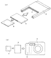
なお、本明細書におけるディスクドライブの好ましい例として、一般にパソコンの場合は、図14(a)に示すように、パソコンに設けられたPCカード用のスロットに挿入されるカード2の受容部のソケット4に電気的に接続されて装填されるディスクドライブ6の外、例えば「click!(登録商標)」のような、PCカードに内蔵されるディスクドライブをも意味する。また、デジタルカメラ3などの場合には、図14(b)に示すように、カメラ3側の受容部5のソケットに電気的に接続されて装填されるディスクドライブ6である。したがって、このディスクドライブ6は極めて小型であり、例えば38mm〜55mmの長さと35mm〜51mmの幅と3mm〜5mmの厚さを有し、磁気ディスクカートリッジ8は、例えば25mm〜36mmの長さおよび幅と1mm〜3mmの厚さを有するものが挙げられる。
【0013】
そして、このような超小型の磁気ディスクカートリッジのハウジングを円盤状に形成し、コイン感覚で磁気記録メディアを取り扱うことが提案されている。すなわち、自動販売機に硬貨を投入するような気軽な感覚で、磁気記録メディアを取り扱うことで、利便性を向上させることが提案されている。
【0014】
ところで、このような超小型の磁気ディスクカートリッジは、超小型なるが故に組立性の点で難点がある。
【0015】
また、このような超小型の磁気ディスクカートリッジにおいて、上記カード型ディスクドライブの磁気ヘッドを磁気ディスクの表面にアクセスさせるための開口を開閉するシャッターが必要になるが、このような超小型の磁気ディスクカートリッジは、超小型なるが故に組付けが容易なシャッターの設計に困難を伴うものである。
【0016】
さらに、このような磁気ディスクカートリッジは大量に市場に供給される一方、これらの大量に供給された磁気ディスクカートリッジは、使用後に回収して、磁気ディスクを入れ替えて再生する等のことをも含むリサイクル処理が施されることが望まれており、磁気ディスクカートリッジに使用する素材の種類を少なくし、かつ、容易に部品を取り出せるようにしたいという要請がある。
【0017】
上述の事情に鑑み、本発明の第1の目的は、組立性に優れた磁気ディスクカートリッジを提供することにある。
【0018】
本発明の第2の目的は、組付けが容易なシャッターを備えた磁気ディスクカートリッジを提供することにある。
【0019】
本発明の第3の目的は、使用する素材の種類が少なく、かつ分解容易なハウジングを備えた磁気ディスクカートリッジを提供することにある。
【0020】
【課題を解決するための手段】
本願第1の発明は、ディスクドライブに装填可能に構成された磁気ディスクカートリッジであって、この磁気ディスクカートリッジは、そのハウジング内に磁気ディスクを回転自在に収容してなるものであり、このハウジングが、上記ディスクドライブの磁気ヘッドを磁気ディスクの表面にアクセスさせるための開口と、この開口を開閉するシャッターとを備えているとともに、上記ハウジングが、下シェルと、この下シェルの内側に上方から嵌合される上シェルとによって構成され、かつすべての構成要素が下シェル内に積上げ方式で組み付けられるように構成されていることを特徴とするものである。
【0021】
その場合、下シェル側のシャッターが下シェルの内側に配置されに内蔵され、上シェル側のシャッターが上シェルの外側に配置され、かつ上下のシャッターがハウジングの開口の前面側において互いに結合されて一体に開閉作動されるように構成されていることが好ましい。
【0022】
また、上記ハウジングは、上記磁気ディスクの輪郭に沿った円弧と、上記磁気ディスクの輪郭に沿った円に外接し、かつ互いに直交する2本の直線とからなる外縁形状を有することが好ましい。
【0023】
その場合、ハウジングの上記互いに直交する2本の直線に沿って直延びる二つの側壁のうちの一方の側壁は、この磁気ディスクカートリッジのディスクドライブへの挿入方向と直交し、他方の側壁は挿入方向と平行であり、かつ上記直線状に延びる二つの側壁によって構成されるコーナー部が、ディスクドライブへの挿入方向に関してトレーリング側の片隅に形成されていることが好ましい。さらに、上記直線状に延びる二つの側壁の外面は、これに隣接する、磁気ディスクの輪郭に沿った円弧を描く周壁の外周面の外接線よりも若干外方に張り出し、および/または、上記二つの側壁の上縁がハウジングの面板部の上面から突出していることが好ましい。
【0024】
なお、本発明(以下の発明においても同じ)においては、上記磁気ディスクが、バリウムフェライト粉末を用いた高記録密度磁気記録媒体であることが好ましい。
【0025】
本願第2の発明は、ディスクドライブに装填可能な磁気ディスクカートリッジであって、この磁気ディスクカートリッジは、ハウジング内に磁気ディスクを回転自在に収容してなるものであり、上記ハウジングが、下シェルと、この下シェルの内側に上方から嵌合される上シェルとによって構成され、かつカード型ディスクドライブの磁気ヘッドを上記磁気ディスクの表面にアクセスさせるための開口と、この開口を開閉するシャッターとを備え、
このシャッターが、下シェルの内面に配設される下側シャッターと、上シェルの外面に配設される上側シャッターとによって構成されているとともに、下側シャッターと上側シャッターとが、カートリッジ組立て時に圧入によって一体化され得る係着手段を備えていることを特徴とするものである。
【0026】
上下シャッターには、一体化後の上下方向の相対移動を阻止する外れ防止手段が設けられていることが好ましい。
【0027】
さらに、上下のシャッターが、ハウジングの開口を上下から閉塞する水平な扇状の主板部と、この主板部の円弧状の外縁に沿って略垂直に折り曲げられた垂直板部とをそれぞれ備え、上記係着手段および外れ防止手段が、双方の垂直板部に設けられていることが好ましい。
【0028】
本願第3の発明は、ディスクドライブに装填可能な磁気ディスクカートリッジであって、この磁気ディスクカートリッジは、ハウジング内に磁気ディスクを回転自在に収容してなるものであり、このハウジングが、上記ディスクドライブの磁気ヘッドを磁気ディスクの表面にアクセスさせるための開口と、この開口を開閉するシャッターとを備えているとともに、ハウジングの上面および側面を形成する金属素材からなる上シェルと、このハウジングの下面および側面を形成する金属素材からなる下シェルとを備え、上シェルの側面と下シェルの側面とが直接嵌合結合されて組み立てられることを特徴とするものである。
【0029】
上記「直接嵌合結合させる」とは、上シェルと下シェルとを弾性変形させたまま組み合わせて、上シェルの側面が下シェルを引き込むように、および下シェルの側面が上シェルを引き込むように上記弾性変形の反力を発生させることによって両者を結合させることを意味するものであり、この弾性変形は塑性変形を伴ったものであってもよい。なお、上記直接嵌合結合させた例としては、圧入やカシメ等が挙げられる。
【0030】
【発明の効果】
本願第1の発明によれば、上記ハウジングが、下シェルと、この下シェルの内側に上方から嵌合される上シェルとによって構成され、かつこの磁気ディスクカートリッジを構成するすべての構成要素が、下シェル内に積上げ方式で組み付けられるようになっていることにより、超小型でありながら組立性に優れたディスクカートリッジを得ることができる。
【0031】
また、このディスクカートリッジのハウジングが、磁気ディスクの輪郭に沿った円弧と、上記磁気ディスクの輪郭に沿った円に外接し、かつ互いに直交する2本の直線とからなる外縁形状を有する場合には、ディスクドライブに挿入する際、ディスクドライブに対して確実に所定の向きで位置決めすることができる。
【0032】
特に、上記ハウジングの互いに直交する2本の直線に沿って延びる二つの側壁の外面が、これに隣接する、磁気ディスクの輪郭に沿った円弧を描く周壁の外周面の外接線よりも若干外方に張り出し、および/または、上記二つの側壁の上縁がハウジングの面板部の上面から突出している場合、ディスクカートリッジを手で摘んだだけで、ディスクカートリッジの表裏およびディスクドライブに対する正しい挿入方向を識別することができるとともに、ディスクドライブ側のカートリッジ挿入用スロットの形状を上記二つの側壁の突出形状に一致させることにより、ディスクカートリッジの誤挿入も防止することができる。
【0033】
また、上記二つの側壁によって画成されるハウジングコーナー部が、磁気ディスクの外周から離れた位置にあるため、このコーナー部に、ハウジングを上下に貫通する位置決め基準孔を設けたり、あるいは、例えば光の反射、透過または特定波長の透過によって情報を読み取ることができる識別片を後から埋め込むこむこともでき、その場合、この識別片によって記録容量等を識別することができるから、ハウジングを共通にすることができるという利点もある。
【0034】
また、本願第2の発明にによれば、上記ハウジングが、下シェルと、この下シェルの内側に上方から嵌合される上シェルとによって構成され、かつ上記シャッターが、下シェルの内側に配設される下側シャッターと、上シェルの外側に配設される上側シャッターとによって構成されているとともに、下側シャッターと上側シャッターとが、カートリッジ組立て時に圧入によって一体化され得る係着手段を備えていることにより、上シェルを下シェルに嵌合させた後に、下シェル内の下側シャッターに上側シャッターを結合させることができるから、ハウジングに対するシャッターの組付けが極めて容易となる利点がある。
【0035】
本願第3の発明によれば、ハウジングの上面および側面を形成する金属素材からなる上シェルと、このハウジングの下面および側面を形成する金属素材からなる下シェルとを備え、上シェルの側面と下シェルの側面とが直接嵌合結合されて組み立てられているので、上記ハウジングを、使用する素材の種類が少なく、かつ分解容易なものとすることができる。これにより、磁気ディスクを入れ替えて磁気ディスクカートリッジを再生する等のことをも含むリサイクル処理をより容易に実施することができ資源を有効利用することができる。
【0036】
本発明による磁気ディスクカートリッジは、特にデジタルカメラに使用するのに適し、取扱いに便利なだけでなく、磁気ディスクであるため安価に製造することができ、記録済みのディスクカートリッジをそのまま保存したり、人にあげたりする使い方ができるようになる。
【0037】
【発明の実施の形態】
以下、本発明による磁気ディスクカートリッジの実施の形態を図面に基づいて説明する。
【0038】
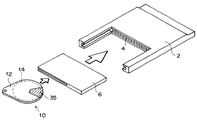
図1は、図14(a)に示したものと同様のパソコンに設けられたPCカード用のスロットに挿入されるPCカード2の受容部のソケット4に電気的に接続されて装填されるディスクドライブ6と、このディスクドライブ6に挿入される本発明による磁気ディスクカートリッジを示している。このディスクカートリッジ10は、偏平なハウジング12内に、バリウムフェライト粉末を用いた高記録密度磁気記録媒体であることが好ましいフレキシブルな円盤状の磁気ディスク14を回転自在に収容してなり、ハウジング12は、ディスクドライブ6の磁気ヘッドを磁気ディスク14の表面にアクセスさせるための開口を開閉する回動式のシャッター35を備えるとともに、ハウジング12の上面および側面を形成する金属素材からなる上シェル30と、このハウジング12の下面および側面を形成する金属素材からなる下シェル20とを備え、上シェル30の側面である周壁30bと下シェル20の側面である側壁部21、22および周壁20bからなる側壁とが直接嵌合結合されて組み立てられたものである。なお、この磁気ディスクカートリッジ10は、磁気ディスク14の輪郭に沿った円と、互いに直角に交わる2本の上記円の外接線とからなる形状の外縁を有する。
【0039】
図1に概略的に示された磁気ディスクカートリッジ10の詳細構成が図2〜図5に示してあり、図2はこの磁気ディスクカートリッジ10を上方から見た斜視図、図3は下方から見た斜視図、図4はシャッターが開かれた状態を図2に対応させて示す斜視図、図5は分解斜視図である。
【0040】
この磁気ディスクカートリッジ10は、そのハウジング12が、金属製の下シェル20と、この下シェル20の内側に上方から圧入されて直接嵌合結合される金属製の上シェル30とによって構成され、図5に示すように、下シェル20側の金属製シャッター25は下シェル20に内蔵され、上シェル30側の金属製シャッター35は上シェル30の外側に配置され、かつすべての構成要素が下シェル20内に積上げ方式で組み付けられるようになっている。
【0041】
図5から明らかなように、下シェル20は、ハウジング12の平面形の輪郭を画成するハウジング12の下面を形成する底板20aと、後述する開口24の部位を除いて底板20aの周縁から上方へ立ち上がるハウジング12の側面を形成する側壁とを備え、この側壁のうち、底板20aの上記2本の外接線に沿う直線状のコーナー外縁から立ち上がる側壁21、22は、その上縁が上シェル30の上面よりもこの面に垂直な方向に突出し、かつ両端部が、これに隣接した円周面を形成する周壁20bの外接線よりも上記面方向に若干外方に張り出して誤挿入防止壁を形成している。そして、一方の側壁21は、このディスクカートリッジ10のディスクドライブ6への挿入方向に関しトレーリング側の隅部において挿入方向と直交するように形成され、他方の側壁22は挿入方向と平行に形成されている。この側壁22の、ディスクドライブ6への挿入方向に関しリーディング側の端部は、ディスクドライブ6に対する挿入位置決め段部22aを形成している。また、側壁21、22によって画成されたハウジング12のコーナー部には、上下シェル30、20を磁気ディスク14の回転軸線と略平行方向に貫通する孔16が形成され、下シェル20側の孔16が位置決め基準孔となっている。
【0042】
磁気ディスク14の中心部には、センターコア15が固定され、下シェル20の底板20aの中央部には、センターコア15の底面を外部に臨ませる中心孔23が形成されている。この中心孔23の周囲の上面には、後述する下側シャッター25の環状部25aを回動可能に軸支する環状壁20cが上記中心孔23と同軸的に形成され、さらに環状壁20cは平坦な上面を備え、この上面上に、後述する下部滑りシート28の中心部を支持するための、より小径の環状壁20dが環状壁20cと同軸的に形成されている。これら大小の環状壁20c、20dは、底板20aに対する搾り加工によって形成することができる。また、下シェル20の底板20aのコーナー部に形成された位置決め基準孔16の周囲にも環状壁(図示は省略)が搾り加工によって形成されている。
【0043】
さらに下シェル20には、中心孔23に関して位置決め基準孔16側とは反対側に、ディスクドライブ6の後述する磁気ヘッドを磁気ディスク14の表面にアクセスさせるための扇形に開いた開口24が、中心孔23の周りに所定の角度範囲に亘って形成され、この開口24を開閉する回転式の下側シャッター25が下シェル20の内側に配置されている。
【0044】
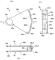
金属板によって形成された下側シャッター25は、その上面図である図6(a)、図6(a)のA−A線に沿った断面図である図6(b)、および図6(a)の右方から見た側面図である図6(c)から明らかなように、下シェル20の上記環状壁20cによって回動可能に軸支される中心の環状部25aと、上記開口24よりも大きい角度範囲に亘って環状部25aから放射方向に水平に延びる扇形の主板部25bと、この主板部25bの円弧状の外縁に沿って上方へ略直角に折り曲げられた垂直板部25cとから構成されている。垂直板部25cの両端縁には、図7に示す上側シャッター35の垂直板部35cの両端に突設された係合舌片35f,35fが係入する切欠き25d,25dが形成されている。
【0045】
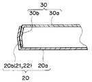
一方、金属板によって形成された上シェル30は、下シェル20の底板20aと略相似形でかつ若干小さい頂板30aと、後述する開口34の部位を除いて頂板30aの周縁から下方へ垂下して、下シェル20の側面周壁が「くの字」型の断面形状にそれぞれ折り曲げられて形成された周壁20bおよび側壁21,22からなる側壁の内側に直接嵌合結合される「くの字」型の断面形状に折り曲げられた周壁30bとを備え、下シェル20の開口24に一致する位置に、ディスクドライブ6の磁気ヘッドを磁気ディスク14の表面にアクセスさせるための開口34が形成され、この開口34を開閉する上側シャッター35が上シェル30の外側に設けられている。
【0046】
さらに、上シェル30の互いに直交する2本の直線によって外縁が画成されているコーナー部には、下シェル20側の位置決め基準孔16に一致する孔16に隣接して、例えば光の反射、透過または特定波長の透過によって情報の読取りが可能な識別片18を後から埋め込むことができる穴17が形成されている。孔16の周囲の下面には環状壁(図示は省略)が絞り加工によって形成されている。
【0047】
下側シャッター25と略相似形をなす金属板で形成された上側シャッター35は、その底面図である図7(a)、図7(a)のB−B線に沿った断面図である図7(b)、および図7(a)の右方から見た側面図である図7(c)から明らかなように、中心の環状部35aと、この環状部35aから放射方向に水平に延びる扇状の主板部35bと、この主板部35bの円弧状の外縁に沿って下方へ略直角に折り曲げられた垂直板部35cとを備えている。この垂直板部35cは、下側シャッター25の垂直板部25cに係着可能な構成を有し、弾性を有する奇数枚(本実施の形態では5枚)の係着片に分割されている。そして、中央および両端に位置する3枚の係着片35c1は、下側シャッター25の垂直板部25cの外面に弾性的に係着し、中間の2枚の係着片35c2は下側シャッター25の垂直板部25cの内面に弾性的に係着し得るように、回動中心からの距離を異にして形成されている。
【0048】
この上側シャッター35は、シャッター25,35を開作動させるために、主板部35bのシャッター開方向リーディング側の外端から上方へ切り起こされた作動用突片35dを備えている。なお、このシャッター作動用突片35dの上縁は、組立て後、ハウジング12のコーナー側壁21,22の上縁と略同一高さになるように規定されている。
【0049】
さらに、上側シャッター35の主板部35bの根元には、後述するシャッター付勢用の渦巻きバネ40の外端40aを係止する切欠き35eが形成され、また、垂直板部35cの両端縁には、図6に示す下側シャッター25の垂直板部25cの両端縁に形成された切欠き25d,25dに係入し得る係合舌片35f,35fが回動中心側に向かって突設されている。
【0050】
このような構成を有する下側シャッター25および上側シャッター35は、連結後の状態を示す上面図である図8(a)、図8(a)のC−C線に沿った断面図である図8(b)、および図8(a)の右方から見た側面図である図8(c)から明らかなように、下側シャッター25の垂直板部25cが、上側シャッター35の垂直板部35cを構成する係着片35c1,35c2の間に圧入されて内外から挟着され、かつ上側シャッター35の垂直板部35cが備えている係合舌片35f,35fが、下側シャッター25の切欠き25d,25dに係入する態様で一体化される。
【0051】
上述のように組立て時に互いに連結される垂直板部25c,35cを回動自在に収容するために、下シェル20の開口24の両側には、シャッター25,35の回動範囲範囲に亘って半径方向外方へ張り出した周壁26,27が形成され、これら周壁26,27の内側に凹部26a,27aを形成している。図2には、これら凹部26a,27aが円弧状溝として表れている。
【0052】
また、上シェル30の頂板30aの上面には、シャッター35の環状部35aおよび主板部35bを収容し、かつシャッター35の回動を許容するための凹部36(図5参照)が形成され、この凹部36の中心部には、シャッター35の環状部35aを回動可能に軸支するための円形凸部37が形成されている。そして、シャッター35の環状部35aが円形凸部37に軸支された場合、シャッター35の主板部35bが凹部36の底面に接し、垂直板部35cが上シェル30の開口34の両側の円弧状周壁30bの外側に被さるようになっている。
【0053】
そして、下側シャッター25の垂直板部25cと、上側シャッター35の垂直板部35cとは、上シェル30が下シェル20に嵌着された後に、上側シャッター35を上シェル30上に載置し、位置合わせ後、上方から力を加えることにより、上側シャッター35の垂直板部35cの係着片35c1,35c2の間に下側シャッター25の垂直板部25cが圧入され、その際に、上側シャッター35の垂直板部35cの両端の係着片35c1、35c1が弾性的に撓むことにより、係合舌片35f,35fが、下側シャッター25の切欠き25d,25dに係入して、図8の状態に一体化されるように構成されている。
【0054】
この磁気ディスクカートリッジ10は、すべての構成部品を下シェル20上に積み上げ式に組み立てることができる特徴を有しており、次に、上記した構成部品以外の構成部品の説明とともに、この磁気ディスクカートリッジ10の組立て方法について図5および図9を参照して説明する。
【0055】
先ず下シェル20の底板20aの環状壁20cに下側シャッター25の環状部25aを嵌める。この場合、シャッター25は、その垂直板部25cが開口24の両側の凹部26a,27aの内壁面に接する態様で主板部35bが下シェル20の開口24を閉鎖した閉位置とする。次に下部滑りシート28を配置する。この滑りシート28は下シェル20の底板20aと略相似形をなし、中心孔から外方に延びる扇形の開口28aと、互いに直交する2本の直線によって画成されたコーナー部とを備え、その中心孔を下シェル20の底板20aの環状壁20dに嵌め、下側の環状壁20cの平坦な上面で支持する。滑りシート28はそのコーナー部に、下シェル20の底板20aの形成された位置決め基準孔16に一致する孔28bを備えており、この孔28bに下シェル20の位置決め基準孔16の周囲に形成された環状壁を嵌めて滑りシート28のコーナー部を支持させる。
【0056】
次に、センターコア15を備えた磁気ディスク14を配置し、さらに、開口38aとコーナー部の孔38bとを備えて下部滑りシート28と同形に形成された上部滑りシート38を配置してから、図9に示すように上シェル30の側面である「くの字型」に折り曲げられた断面形状を有する周壁30bを、下シェル20の側面である同じく「くの字型」に折り曲げられた周壁20b、側壁21および側壁22からなる側壁の内側に直接嵌合結合させる。これにより、上記凹部26a,27aにあるシャッター25の垂直板部25cが、上記凹部26a,27aと上シェル30の周壁30bとによって形成される溝内で溝に沿って移動可能になる。また、上シェル30の頂板30aのコーナー部に形成されている孔16の環状壁が上部滑りシート38のコーナー部の孔38bに嵌められて、滑りシート38のコーナー部が支持されるとともに、上下の滑りシート28,38のコーナー部は、上シェル30のコーナー部の側壁の内壁面によっても支持される。
【0057】
次に、上側のシャッター35を、その環状部35aが上シェル30上面の円形凸部37に軸支される態様で上方から組み付け、図8に示すように、その垂直板部35cの係着片35c1,35c2の間に下側シャッター25の垂直板部25cを圧入してシャッター25,35を一体化するとともに、上側シャッター35の垂直板部35cの両端の係合舌片35f,35fを、下側シャッター25の切欠き25d,25dに係入させる。次に、シャッター付勢用の平面形状の渦巻きバネ40を円形凸部37に嵌め、この渦巻きバネ40の内端40bを円形凸部37のスリット37bに係入させ、外端40aをシャッター35の主板部35bの切欠き35eに係止することによって、シャッター25,35は閉方向に付勢され、かつ閉位置に保持される。
【0058】
次に、上シェル30の開口34に倣う開口41aを備え、かつ上シェル30の凹部36よりも大径の金属製のカバープレート41を、図5に破線41bで示されている中心部を上シェル30の円形凸部37上に接着し、周縁部を上シェル30の頂板30a上に接着することによって、渦巻きバネ40が外れないようにするとともに、カバープレート41の下面側にシャッター35の回動空間を画成し、以上をもってディスクカートリッジ10の組立てが完了する。
【0059】
上記カバープレート41の上面は凹凸面とすることによって、ディスクカートリッジ10の表裏を触感で識別することができる。あるいは、カバープレート41の上面に蛍光塗料を塗布して、暗闇の中でもディスクカートリッジ10の表裏を識別できるようにしてもよい。さらにはカバープレート41の上面にマット加工を施して、鉛筆で数字等を書き込めるようにしてもよい。あるいは図示のように、カバープレート41の上面に例えば紙製の円形ラベル42を貼付して、これに情報を書き込むことができるようにしてもよい。その場合、カバープレート41の開口41aの輪郭に沿ったミシン目42aをラベル42に設け、使用時にこのミシン目42aで囲まれた領域42bを切り取るようにすることによって、未使用のカートリッジ10のバージン保証に供することができ、また露出した上側シャッター35の保護を図ることもできる。
【0060】
なお、上下シェル30,20の周壁30b,20b同士を弾性的に嵌合させるために、周壁30b,20bのいずれか一方、例えば周壁30bに、図示のような複数のスリット39を設けることによって、周壁30bに弾性を与えることが好ましい。また、下側シャッター25の主板部25bの上面および上側シャッター35の主板部35bの下面には、上シェル30の開口34および滑りシート28,38の開口28a,38aを通して回転中の磁気ディスク14の表面に接触するクリーニング部材44がそれぞれ放射状に取り付けられている。クリーニング部材44は、シャッター25,35の主板部25b,35bの閉方向の端縁に沿って放射状に取り付けられており、これらクリーニング部材44は、磁気ディスク14が静止している際に磁気ディスク14がシャッター25,35の主板部25b,35bに接触するのを防止する機能も有する。
【0061】
また、シャッター25、35が開いて磁気ディスク14が回転しているときにクリーニング部材44が磁気ディスク14の表面の一か所のみに接触していると磁気ディスク14の回転時のバランスが悪いので、磁気ディスク14の保護用に設けられている滑りシート28,38の磁気ディスク14に面する表面に、クリーニング部材44と同一高さを有する突条45を、シャッター開時のクリーニング部材44に対して180度偏位した位置に放射状に設けることが好ましい。さらに各2本の突条45を、シャッター開時のクリーニング部材44に対して120度偏位した位置に放射状に設けてもよい。
【0062】
次に、上記圧入方式とは異なり、上シェルと下シェルとを嵌合方式によって直接嵌合結合させる場合について説明する。図10は上シェルと下シェルとを嵌合方式によって組み立てる様子を示した分解斜視図、図11は上記嵌合方式によって組み立てられた磁気ディスクカートリッジの斜視図である。
【0063】
図10に示すように、下シェル60に、下シェル60の周壁60bの一部にカシメ用突起部60cを形成すると共に、上シェル65に、下シェル60と上シェル65とが組み合わされたときにカシメ用突起部60cに対応した位置となる上シェル65の周壁65bの一部にカシメ受部65cを形成する。カシメ用突起部60cが形成されている下シェル60とカシメ受部65cが形成されている上シェル65とを組み合わせた後、図11に示すようにカシメ用突起部60cをカシメ受部65c側に折り曲げて、下シェル60と上シェル65とを直接嵌合結合させる。このようにして、上述した磁気ディスクカートリッジを結合するようにしてもよい。
【0064】
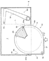
図12は、ディスクドライブ6に磁気ディスクカートリッジ10を挿入する場合の状態を示す概略的平面図、図13は、磁気ディスクカートリッジ10がディスクドライブ6に装着された状態を示す概略的平面図である。なお、図12および図13は、磁気ディスクカートリッジ10とディスクドライブ6との相対位置関係の説明に供するもので、細部については省略してある。
【0065】
ディスクドライブ6は、カートリッジ挿入スロット6aと、内部のカートリッジ収容スペース7とを備え、さらに、通常はカートリッジ10の挿入通路(通路の端縁を破線Lで示してある)外に退避している上下一対の回動式アーム51を備えたヘッドアセンブリ50と、ディスクドライブ6へのカートリッジ10の挿入に伴って、シャッター35の作動用突片35dに係合して、シャッター25,35を開作動させるシャッター作動部材52とを備えている。アーム51の先端には磁気ヘッド53が互いに対向するようにそれぞれ固定されて、磁気ディスク14の両面にアクセスするように構成されている。
【0066】
また、上記カートリッジ挿入スロット6aは、ディスクドライブ6のヘッドアセンブリ50側とは反対側の側壁面6bに接して形成され、この側壁面6bに、磁気ディスクカートリッジ10の側壁22の挿入位置決め段部22aに係合する位置決め突起6cが形成されている。また、図示は省略するが、カートリッジ挿入用スロット6aの上縁には、磁気ディスクカートリッジ10の側壁22の上縁部と、閉位置にあるシャッター35の作動用作動用突片35dとに対応する位置に、これらの通過を許容する切欠きが形成されて、磁気ディスクカートリッジ10の誤挿入を防止している。
【0067】
磁気ディスクカートリッジ10は、図12に矢示する方向からディスクドライブ6に挿入され、その際に、シャッター35が備えている作動用突片35dに、ディスクドライブ6のシャッター作動部材52が係合して、磁気ディスクカートリッジ10の挿入に伴ってシャッター25,35が開作動される。その場合、上側シャッター35の作動用突片35dが磁気ディスクカートリッジ10の挿入方向に対して右側方に設けられているため、磁気ディスクカートリッジ10の挿入に伴って、シャッター作動部材52から磁気ディスクカートリッジ10に対しこれを図の時計方向に回動させようとする力Fが加えられるが、ハウジング12のコーナー部の直線状に延びる側壁22がディスクドライブ6の内壁面6bに当接して回動が阻止されるようになっている。そして、図13に示すように、磁気ディスクカートリッジ10が完全にディスクドライブ6内に挿入されると、ディスクドライブ6が備えている図示しない位置決め突起が位置決め基準孔16に係入し、さらに必要に応じてハウジング12の側壁22に形成されている位置決め凹部22bに、ディスクドライブ6側の図示しない位置決め突起が係入して、磁気ディスクカートリッジ10がディスクドライブ6内の所定位置に係止される。そして、ヘッドアセンブリ50のアーム51が図の反時計方向に回動して、磁気ヘッド53が磁気ディスク14の両面にアクセスする。
【0068】
以上の説明で明らかなように、本発明による磁気ディスクカートリッジ10は、そのハウジング12が、下シェル20と、この下シェル20の内側に上方から嵌着される上シェル30とによって構成され、かつこの磁気ディスクカートリッジ10を構成するすべての構成要素が、上シェル30の円形凹部37上に接着されるカバープレート41を除いては、全て下シェル内に積上げ方式で嵌合により組み付けられるようになっているため、超小型でありながら組立て性および分解性に優れているという利点を有するものである。
【0069】
また、ハウジング12が、磁気ディスク14の輪郭に沿った円と、互いに直角に交わる2本の上記円の外接線とからなる形状の外縁からなる平面形を有することにより、ディスクドライブ6に挿入する際、ディスクドライブ6に対して確実に所定の向きで位置決めすることができる。
【0070】
特に、ハウジング12の互いに直角に交わる2本の外接線に沿って直線状に延びる二つの側壁21,22の外面が、これに隣接する、磁気ディスク14の輪郭に沿った円を描く周壁20bの外周面の外接線よりも若干外方に張り出し、かつ上記二つの側壁21,22の上縁がハウジング12の面板部の上面から突出しているため、ディスクカートリッジ10を手で摘んだだけで、ディスクカートリッジ10の表裏およびディスクドライブ6に対する正しい挿入方向を識別することができるとともに、ディスクドライブ6側のカートリッジ挿入スロット6aの形状が側壁21,22の突出形状に一致させてあることにより、ディスクカートリッジ10の誤挿入も防止することができる。
【0071】
また、二つの側壁21,22によって画成されるハウジングコーナー部が、磁気ディスク14の外周から離れた位置にあるため、このコーナー部に、ハウジングを上下に貫通する位置決め基準孔16を設けたり、あるいは、例えば光の反射、透過または特定波長の透過によって情報を読み取ることができる識別片18を共通のハウジング12に後から埋め込むこむこともでき、その場合、この識別片によって記録容量等を識別することができるから、ハウジングを共通にすることができる利点もある。
【0072】
さらに、下側シャッター25と上側シャッター30とが、カートリッジ組立て時に、上側シャッター35の垂直板部35cを構成する係着片35c1,35c2の間に下側シャッター25の垂直板部25cを圧入することによって、上下のシャッター35,25が一体化されるように構成されていることにより、上シェル30を下シェル20に嵌合させた後に、下シェル20内の下側シャッター25に上側シャッター35を結合させることができるから、ハウジング12に対するシャッターの組付けが極めて容易となる利点がある。
【0073】
また、上側シャッター35の垂直板部35cの両端に係合舌片35f,35fが、上記圧入に伴って、下側シャッター25の切欠き25d,25dに係入するように構成されているから、上下のシャッター35,25の結合状態が外れる虞れもなくなる。
【0074】
さらに、下シェル20、上シェル30、カバープレート41およびシャッター25、35が全て金属で形成されているので、磁気ディスクカートリッジ全体のリサイクル処理をより容易に実施することができる。
【図面の簡単な説明】
【図1】本発明による磁気ディスクカートリッジを、このディスクカートリッジが挿入されるディスクドライブと、このディスクドライブが装填されるカードスロットを備えた電子機器とともに示す概略的説明図
【図2】本発明による磁気ディスクカートリッジを上方から見た斜視図
【図3】図2の磁気ディスクカートリッジを下方から見た斜視図
【図4】図2の磁気ディスクカートリッジのシャッターが開かれた状態を示す図2に対応する斜視図
【図5】図2の磁気ディスクカートリッジの分解斜視図
【図6】下側シャッターを示す図で、図6(a)はその上面図、図6(b)は図6(a)のA−A線に沿った断面図、図6(c)は図6(a)の右方から見た側面図
【図7】上側シャッターを示す図で、図7(a)はその底面図、図7(b)は図7(a)のB−B線に沿った断面図、図7(c)は図7(a)の右方から見た側面図
【図8】上下のシャッタの連結後の状態を示す図で、図8(a)はその上面図、図8(b)は図8(a)のC−C線に沿った断面図、図8(c)は図8(a)の右方から見た側面図
【図9】下シェルと上シェルとが直接嵌合結合されて組み立てられた状態を示す断面図
【図10】上シェルと下シェルとを嵌合方式によって組み立てる様子を示す分解斜視図
【図11】嵌合方式によって組み立てられた磁気ディスクカートリッジの斜視図
【図12】本発明の磁気ディスクカートリッジがディスクドライブに挿入される様子を示す概略的平面図
【図13】本発明の磁気ディスクカートリッジがディスクドライブに装着された状態を示す概略的平面図
【図14】本発明の前提となるディスクドライブを、このディスクドライブが装填されるカードスロットを備えた電子機器とともに示す概略的説明図
【符号の説明】
6 ディスクドライブ
10 磁気ディスクカートリッジ
12 ハウジング
14 磁気ディスク
15 センターコア
18 識別片
20 下シェル
21,22 側壁
24,34 磁気ヘッドアクセス用開口
25,35 シャッター
28、38 滑りシート
30 上シェル
40 渦巻きスプリング
41 カバープレート
42 ラベル
44 クリーニング部材
45 突条
50 ヘッドアセンブリ
51 アーム
52 シャッター作動部材
53 磁気ヘッド[0001]
BACKGROUND OF THE INVENTION
The present invention relates to a small magnetic disk cartridge that can be exchangeably loaded into a disk drive or the like provided in a digital still camera, a digital video camera, a notebook computer, or the like.
[0002]
[Prior art]
2. Description of the Related Art Conventionally, various recording media are removably loaded into a card slot of an electronic device such as a digital still camera, a digital video camera, and a notebook personal computer, and recording and reproduction are performed. As such a recording medium, various types such as a semiconductor memory type, a hard disk type, an optical disk type, and a small magnetic disk such as a floppy (registered trademark) disk are put to practical use. Yes.
[0003]
[Problems to be solved by the invention]
Among them, the semiconductor memory is easy to handle and the recording capacity is appropriately large, so it is the most popular but relatively expensive. Therefore, in a digital camera or the like using these memories, it is common to transfer the captured image data to a personal computer or the like, and then delete the data and use the recording medium repeatedly.
[0004]
A hard disk type having a capacity of 340 MB or 1 GB is known, but this is also expensive, and the data is transferred and stored elsewhere, and the recording medium is repeatedly used.
[0005]
The optical disk type has a large recording capacity for its size. For example, 256 MB of data can be recorded in a size of 35 mm × 41 mm × 11 mm, and a recording capacity of 512 MB is also being realized. However, since the optical disk takes time to write, there is a drawback that the recording speed is slow.
[0006]
On the other hand, a magnetic disk such as a floppy (registered trademark) disk having a small size of about 50 mm × 55 mm × 2 mm can be inserted into a disk drive of a size that can be inserted into a card slot of a personal computer or the like. As is known, this has a small capacity of 40 MB, is insufficient in terms of recording camera images, and is not suitable for digital cameras.
[0007]
In recent years, digital cameras have been combined with the social backgrounds in which PCs have become popular, such as the ease of recording, improved image quality through the development of image sensors, the possibility of data deletion and transfer, and the size of recording capacity. Although it is rapidly widespread, recording media (hereinafter referred to as “media”) are limited in terms of price and capacity as described above, and thus there are limitations on the manner of use. For example, because the media is expensive, do not have many media in one camera, and use the same media repeatedly by transferring it to a PC and deleting it when the data is full. As described above, this is normal. For this reason, there may be a shortage of recording media on the road, and it is not possible to store the media containing the data as it is or give it to a person.
[0008]
Therefore, realization of a large-capacity and inexpensive small medium is desired so that data taken with a digital camera can be stored as it is or can be easily given to a person. In addition, in a personal computer, it is desired to realize a large-capacity and inexpensive small medium capable of storing data and passing it to a person.
[0009]
In response to such requests, PCs, digital cameras, etc. as large-capacity and inexpensive small media that can store data taken with a digital camera or PC data as it is, or can be easily given to people A medium comprising a card-type disk drive that can be loaded into an electronic device and a magnetic disk cartridge that can be loaded into the disk drive is conceivable. That is, as such a magnetic disk cartridge, a flexible magnetic disk capable of high-density magnetic recording is rotatably accommodated in a housing having an open / close shutter, and for example, a magnetic disk cartridge having a recording capacity of 200 MB or more is provided. Is considered. As a high recording density magnetic recording medium, a metal thin film formed by a metal vapor deposition method, a metal thin film formed by a sputtering method, or a barium ferrite powder or a metal powder (for example, a ferromagnetic metal powder) is used. Can be adopted. As an example of using barium ferrite powder, there is Japanese Patent Application No. 2001-31864 filed by the present applicant.
[0010]
"High recording density magnetic recording medium using barium ferrite powder" is a magnetic disk containing barium ferrite powder in the magnetic layer, using a material capable of realizing high recording density, for example, The nonmagnetic layer disclosed in Japanese Patent Application No. 2001-205290 includes a nonmagnetic layer containing nonmagnetic powder and a binder, and a ferromagnetic powder and binder as hexagonal ferrite powder on at least one surface of the nonmagnetic support. A magnetic recording medium having a magnetic layer in this order, the nonmagnetic layer containing 10 to 50 parts by mass of carbon black having an average particle size of 10 to 30 nm with respect to 100 parts by mass of the nonmagnetic powder, and the thickness of the magnetic layer The standard deviation b of the intensity with respect to the average intensity a of the element caused by the ferromagnetic powder by electron microanalysis is 0.03 ≦ b / a ≦ 0.4, One, below the center plane average roughness Ra of the magnetic layer is 5 nm, the average 10-point roughness Rz is a magnetic recording medium is 40nm or less. For a magnetic disk using this material, information is recorded and reproduced using a magnetic head such as an MR head capable of high recording density.
[0011]
According to the above media, it is possible to realize a high recording density medium having a recording capacity of 200 MB or more, preferably 500 MB or more, so that, for example, a still image can be recorded as about 1 MB and 500 sheets can be recorded. In the case of a moving image, video content of about 30 minutes can be recorded. Accordingly, it is possible to record a moving image shot by a digital camera, a moving image distributed by a mobile phone, and the like, and it is possible to improve user convenience when using content. Of course, it can be conveniently used as an inexpensive large-capacity data storage medium in a personal computer, and its convenience is great.
[0012]
As a preferred example of the disk drive in the present specification, generally in the case of a personal computer, as shown in FIG. 14 (a), the socket of the receiving portion of the
[0013]
Then, it has been proposed that the housing of such an ultra-small magnetic disk cartridge is formed in a disk shape and the magnetic recording medium is handled like a coin. That is, it has been proposed to improve convenience by handling magnetic recording media in a casual manner such as inserting coins into a vending machine.
[0014]
By the way, such an ultra-small magnetic disk cartridge has a difficulty in assembling because it is ultra-small.
[0015]
Further, in such an ultra-small magnetic disk cartridge, a shutter that opens and closes an opening for allowing the magnetic head of the card-type disk drive to access the surface of the magnetic disk is required. Since the cartridge is extremely small, it is difficult to design a shutter that is easy to assemble.
[0016]
Furthermore, while such magnetic disk cartridges are supplied to the market in large quantities, these magnetic disk cartridges supplied in large quantities are also recycled, including recovering after use, replacing the magnetic disk for playback, etc. There is a demand for processing, and there is a demand to reduce the types of materials used in the magnetic disk cartridge and to allow easy removal of parts.
[0017]
In view of the above circumstances, a first object of the present invention is to provide a magnetic disk cartridge excellent in assemblability.
[0018]
A second object of the present invention is to provide a magnetic disk cartridge having a shutter that can be easily assembled.
[0019]
A third object of the present invention is to provide a magnetic disk cartridge provided with a housing that uses few types of materials and can be easily disassembled.
[0020]
[Means for Solving the Problems]
A first invention of the present application is a magnetic disk cartridge configured to be loadable in a disk drive, and the magnetic disk cartridge is configured such that a magnetic disk is rotatably accommodated in the housing. And an opening for allowing the magnetic head of the disk drive to access the surface of the magnetic disk, and a shutter for opening and closing the opening, and the housing is fitted into the lower shell and the lower shell from above. And an upper shell to be combined, and all components are assembled in a stacked manner in the lower shell.
[0021]
In that case, the shutter on the lower shell side is disposed inside the lower shell and incorporated therein, the shutter on the upper shell side is disposed on the outer side of the upper shell, and the upper and lower shutters are coupled to each other on the front side of the opening of the housing. It is preferable to be configured to be integrally opened and closed.
[0022]
The housing preferably has an outer edge shape formed by an arc along the contour of the magnetic disk and two straight lines circumscribing a circle along the contour of the magnetic disk and orthogonal to each other.
[0023]
In this case, one of the two side walls extending straight along the two orthogonal lines of the housing is orthogonal to the direction in which the magnetic disk cartridge is inserted into the disk drive, and the other side wall is in the insertion direction. It is preferable that a corner portion constituted by the two side walls extending in parallel with the straight line is formed at one corner on the trailing side in the insertion direction into the disk drive. Further, the outer surfaces of the two side walls extending in a straight line project slightly outward from the circumscribing line of the outer peripheral surface of the peripheral wall adjacent to the outer wall and describing the arc along the contour of the magnetic disk. It is preferable that the upper edges of the two side walls protrude from the upper surface of the face plate portion of the housing.
[0024]
In the present invention (the same applies to the following inventions), the magnetic disk is preferably a high recording density magnetic recording medium using barium ferrite powder.
[0025]
A second invention of the present application is a magnetic disk cartridge that can be loaded into a disk drive. The magnetic disk cartridge is a housing in which a magnetic disk is rotatably accommodated in a housing. And an upper shell that is fitted into the lower shell from above, and an opening for allowing the magnetic head of the card type disk drive to access the surface of the magnetic disk, and a shutter for opening and closing the opening. Prepared,
This shutter is composed of a lower shutter disposed on the inner surface of the lower shell and an upper shutter disposed on the outer surface of the upper shell, and the lower shutter and the upper shutter are press-fitted when the cartridge is assembled. It is characterized in that it is provided with engaging means that can be integrated by means of.
[0026]
The upper and lower shutters are preferably provided with a detachment prevention means for preventing the relative movement in the vertical direction after integration.
[0027]
Further, the upper and lower shutters each include a horizontal fan-shaped main plate portion that closes the housing opening from above and below, and a vertical plate portion that is bent substantially vertically along the arc-shaped outer edge of the main plate portion. It is preferable that the attaching means and the detachment preventing means are provided on both vertical plate portions.
[0028]
A third invention of the present application is a magnetic disk cartridge that can be loaded into a disk drive, and the magnetic disk cartridge is a housing in which a magnetic disk is rotatably accommodated. And an upper shell made of a metal material that forms the upper and side surfaces of the housing, a lower surface of the housing, and an opening for opening and closing the opening. A lower shell made of a metal material that forms the side surface, and the side surface of the upper shell and the side surface of the lower shell are assembled by being directly fitted and connected.
[0029]
The above-mentioned “direct fitting and coupling” means that the upper shell and the lower shell are combined while being elastically deformed so that the side surface of the upper shell pulls the lower shell, and the side surface of the lower shell pulls the upper shell It means that both are combined by generating a reaction force of the elastic deformation, and this elastic deformation may be accompanied by plastic deformation. Examples of the direct fitting and coupling include press fitting and caulking.
[0030]
【The invention's effect】
According to the first invention of the present application, the housing is constituted by a lower shell and an upper shell fitted from above to the inside of the lower shell, and all the components constituting the magnetic disk cartridge are: By being assembled in a stacked manner in the lower shell, it is possible to obtain a disc cartridge excellent in assemblability while being ultra-small.
[0031]
In the case where the housing of the disk cartridge has an outer edge shape composed of an arc along the contour of the magnetic disk and two straight lines circumscribing a circle along the contour of the magnetic disk and perpendicular to each other When inserted into the disk drive, the disk drive can be reliably positioned in a predetermined direction.
[0032]
In particular, the outer surfaces of the two side walls extending along two straight lines perpendicular to each other of the housing are slightly outward from the outer tangent of the outer peripheral surface of the peripheral wall that forms an arc along the contour of the magnetic disk adjacent thereto. If the upper edge of the two side walls protrudes from the upper surface of the face plate of the housing, the correct insertion direction of the disk cartridge can be identified by simply picking the disk cartridge by hand. In addition, it is possible to prevent erroneous insertion of the disk cartridge by matching the shape of the cartridge insertion slot on the disk drive side with the protruding shape of the two side walls.
[0033]
Further, since the housing corner portion defined by the two side walls is located away from the outer periphery of the magnetic disk, a positioning reference hole penetrating the housing up and down is provided in the corner portion, or, for example, an optical An identification piece from which information can be read by reflection, transmission or transmission of a specific wavelength can be embedded later. In this case, since the recording capacity can be identified by this identification piece, a common housing is used. There is also an advantage of being able to.
[0034]
According to the second invention of the present application, the housing is constituted by a lower shell and an upper shell fitted from above to the inside of the lower shell, and the shutter is arranged inside the lower shell. The lower shutter and the upper shutter disposed outside the upper shell are provided, and the lower shutter and the upper shutter are provided with engaging means that can be integrated by press-fitting when the cartridge is assembled. Thus, after the upper shell is fitted to the lower shell, the upper shutter can be coupled to the lower shutter in the lower shell, so that there is an advantage that the assembly of the shutter to the housing becomes extremely easy.
[0035]
According to the third invention of the present application, it is provided with an upper shell made of a metal material forming the upper surface and the side surface of the housing, and a lower shell made of a metal material forming the lower surface and the side surface of the housing. Since the side surface of the shell is assembled by being directly fitted and coupled, the housing can be made of a small number of materials and can be easily disassembled. Thereby, the recycling process including the replacement of the magnetic disk and the reproduction of the magnetic disk cartridge can be more easily performed, and the resources can be effectively used.
[0036]
The magnetic disk cartridge according to the present invention is particularly suitable for use in a digital camera and is not only convenient for handling, but also can be manufactured at a low cost because it is a magnetic disk. You will be able to use it for others.
[0037]
DETAILED DESCRIPTION OF THE INVENTION
Embodiments of a magnetic disk cartridge according to the present invention will be described below with reference to the drawings.
[0038]
FIG. 1 shows a disk that is electrically connected to a
[0039]
A detailed configuration of the
[0040]
The
[0041]
As is apparent from FIG. 5, the
[0042]
A
[0043]
Further, the
[0044]
The
[0045]
On the other hand, the
[0046]
Further, at the corner portion where the outer edge is defined by two straight lines orthogonal to each other of the
[0047]
The
[0048]
The
[0049]
Further, a
[0050]
The
[0051]
As described above, the
[0052]
Further, a recess 36 (see FIG. 5) for accommodating the
[0053]
The
[0054]
The
[0055]
First, the
[0056]
Next, the
[0057]
Next, the
[0058]
Next, a
[0059]
By making the upper surface of the
[0060]
In order to elastically fit the
[0061]
If the cleaning
[0062]
Next, unlike the press-fitting method, a case where the upper shell and the lower shell are directly fitted and joined by a fitting method will be described. FIG. 10 is an exploded perspective view showing how the upper shell and the lower shell are assembled by the fitting method, and FIG. 11 is a perspective view of the magnetic disk cartridge assembled by the fitting method.
[0063]
As shown in FIG. 10, when the
[0064]
FIG. 12 is a schematic plan view showing a state in which the
[0065]
The
[0066]
The cartridge insertion slot 6a is formed in contact with a
[0067]
The
[0068]
As is apparent from the above description, the
[0069]
Further, the
[0070]
In particular, the outer surface of two
[0071]
Further, since the housing corner portion defined by the two
[0072]
Further, the
[0073]
Further, the engaging
[0074]
Furthermore, since the
[Brief description of the drawings]
FIG. 1 is a schematic explanatory view showing a magnetic disk cartridge according to the present invention together with a disk drive into which the disk cartridge is inserted and an electronic apparatus having a card slot into which the disk drive is loaded.
FIG. 2 is a perspective view of a magnetic disk cartridge according to the present invention as viewed from above.
FIG. 3 is a perspective view of the magnetic disk cartridge of FIG. 2 as viewed from below.
4 is a perspective view corresponding to FIG. 2, showing a state in which the shutter of the magnetic disk cartridge of FIG. 2 is opened.
5 is an exploded perspective view of the magnetic disk cartridge of FIG.
6A is a top view of the lower shutter, FIG. 6B is a cross-sectional view taken along the line AA of FIG. 6A, and FIG. Side view seen from the right side of Fig. 6 (a)
7A is a bottom view of the upper shutter, FIG. 7B is a cross-sectional view taken along the line BB of FIG. 7A, and FIG. 7 (a) side view from the right
8A and 8B are views showing a state after the upper and lower shutters are connected, in which FIG. 8A is a top view thereof, FIG. 8B is a cross-sectional view taken along the line CC in FIG. 8 (c) is a side view as seen from the right side of FIG. 8 (a).
FIG. 9 is a cross-sectional view showing a state in which the lower shell and the upper shell are assembled by directly fitting and joining together.
FIG. 10 is an exploded perspective view showing how the upper shell and the lower shell are assembled by a fitting method.
FIG. 11 is a perspective view of a magnetic disk cartridge assembled by a fitting method.
FIG. 12 is a schematic plan view showing how the magnetic disk cartridge of the present invention is inserted into a disk drive.
FIG. 13 is a schematic plan view showing a state in which the magnetic disk cartridge of the present invention is mounted in a disk drive.
FIG. 14 is a schematic explanatory view showing a disk drive as a premise of the present invention together with an electronic device having a card slot into which the disk drive is loaded.
[Explanation of symbols]
6 Disk drive
10 Magnetic disk cartridge
12 Housing
14 Magnetic disk
15 Center core
18 Identification piece
20 Lower shell
21, 22 side wall
24, 34 Magnetic head access opening
25, 35 shutter
28, 38 Sliding seat
30 Upper shell
40 spiral spring
41 Cover plate
42 labels
44 Cleaning member
45 ridges
50 head assembly
51 arms
52 Shutter operating member
53 Magnetic head
Claims (7)
該磁気ディスクカートリッジが、ハウジング内に磁気ディスクを回転自在に収容してなるものであり、
前記ハウジングが、前記磁気ディスクの輪郭に沿った円弧と、前記輪郭に沿った円に外接し、かつ互いに直交する2本の直線とからなる外縁形状を有し、
前記ハウジングが、前記ディスクドライブの磁気ヘッドを前記磁気ディスクの表面にアクセスさせるための開口と、該開口を開閉するシャッターとを備えているとともに、
前記ハウジングが、金属製の下シェルと、該下シェルの内側に上方から嵌合される金属製の上シェルとによって構成され、
前記下シェルは、底板と、前記開口の部位を除いて前記底板の周縁から上方へ立ち上がる側壁とを備え、
前記上シェルは、頂板と、前記開口の部位を除いて前記頂板の周縁から下方へ垂下して、前記下シェルの側壁の内側に直接嵌合結合される側壁とを有し、
すべての構成要素が、前記下シェル内に積上げ方式で組み付けられるように構成されていることを特徴とする磁気ディスクカートリッジ。A magnetic disk cartridge that can be loaded into a disk drive,
The magnetic disk cartridge is a housing in which a magnetic disk is rotatably accommodated in a housing,
The housing has an outer edge shape composed of an arc along the contour of the magnetic disk and two straight lines circumscribing a circle along the contour and orthogonal to each other;
The housing includes an opening for allowing the magnetic head of the disk drive to access the surface of the magnetic disk, and a shutter for opening and closing the opening,
Said housing is configured and lower shell metal, by a metal upper shell fitted from above into the inside of the lower shell,
The lower shell includes a bottom plate and a side wall that rises upward from a peripheral edge of the bottom plate except for the portion of the opening,
The upper shell includes a top plate, and a side wall that hangs downward from a peripheral edge of the top plate except for the portion of the opening and is directly fitted and coupled to the inside of the side wall of the lower shell,
A magnetic disk cartridge characterized in that all the components are assembled in a stacked manner in the lower shell.
該磁気ディスクカートリッジが、ハウジング内に磁気ディスクを回転自在に収容してなるものであり、
前記ハウジングが、前記磁気ディスクの輪郭に沿った円弧と、前記輪郭に沿った円に外接し、かつ互いに直交する2本の直線とからなる外縁形状を有し、
前記ハウジングが、金属製の下シェルと、該下シェルの内側に上方から嵌合される金属製の上シェルとによって構成され、かつ前記ディスクドライブの磁気ヘッドを前記磁気ディスクの表面にアクセスさせるための開口と、該開口を開閉するシャッターとを備え、
前記下シェルは、底板と、前記開口の部位を除いて前記底板の周縁から上方へ立ち上がる側壁とを備え、
前記上シェルは、頂板と、前記開口の部位を除いて前記頂板の周縁から下方へ垂下して、前記下シェルの側壁の内側に直接嵌合結合される側壁とを有し、
前記シャッターが、前記下シェルの内側に配設される下側シャッターと、前記上シェルの外側に配設される上側シャッターとによって構成されているとともに、前記下側シャッターと前記上側シャッターとが、カートリッジ組立て時に圧入によって一体化され得る係着手段を備えていることを特徴とする磁気ディスクカートリッジ。A magnetic disk cartridge that can be loaded into a disk drive,
The magnetic disk cartridge is a housing in which a magnetic disk is rotatably accommodated in a housing,
The housing has an outer edge shape composed of an arc along the contour of the magnetic disk and two straight lines circumscribing a circle along the contour and orthogonal to each other;
The housing includes a metal lower shell and a metal upper shell fitted from above into the lower shell, and allows the magnetic head of the disk drive to access the surface of the magnetic disk. And a shutter for opening and closing the opening,
The lower shell includes a bottom plate and a side wall that rises upward from a peripheral edge of the bottom plate except for the portion of the opening,
The upper shell includes a top plate, and a side wall that hangs downward from a peripheral edge of the top plate except for the portion of the opening and is directly fitted and coupled to the inside of the side wall of the lower shell,
The shutter is configured by a lower shutter disposed inside the lower shell and an upper shutter disposed outside the upper shell, and the lower shutter and the upper shutter are: A magnetic disk cartridge comprising engaging means that can be integrated by press-fitting when the cartridge is assembled.
Priority Applications (2)
| Application Number | Priority Date | Filing Date | Title |
|---|---|---|---|
| JP2002080060A JP3919085B2 (en) | 2001-11-21 | 2002-03-22 | Magnetic disk cartridge |
| US10/298,928 US6922312B2 (en) | 2001-11-21 | 2002-11-19 | Disk cartridge having upper shell fitted inside lower shell to enclose lower shutter with upper shutter outside upper shell |
Applications Claiming Priority (7)
| Application Number | Priority Date | Filing Date | Title |
|---|---|---|---|
| JP2001-355662 | 2001-11-21 | ||
| JP2001355662 | 2001-11-21 | ||
| JP2001-387073 | 2001-12-20 | ||
| JP2001387073 | 2001-12-20 | ||
| JP2001391966 | 2001-12-25 | ||
| JP2001-391966 | 2001-12-25 | ||
| JP2002080060A JP3919085B2 (en) | 2001-11-21 | 2002-03-22 | Magnetic disk cartridge |
Publications (3)
| Publication Number | Publication Date |
|---|---|
| JP2003257150A JP2003257150A (en) | 2003-09-12 |
| JP2003257150A5 JP2003257150A5 (en) | 2005-02-17 |
| JP3919085B2 true JP3919085B2 (en) | 2007-05-23 |
Family
ID=27482692
Family Applications (1)
| Application Number | Title | Priority Date | Filing Date |
|---|---|---|---|
| JP2002080060A Expired - Fee Related JP3919085B2 (en) | 2001-11-21 | 2002-03-22 | Magnetic disk cartridge |
Country Status (2)
| Country | Link |
|---|---|
| US (1) | US6922312B2 (en) |
| JP (1) | JP3919085B2 (en) |
Families Citing this family (8)
| Publication number | Priority date | Publication date | Assignee | Title |
|---|---|---|---|---|
| US8397998B1 (en) * | 1999-10-23 | 2013-03-19 | Ultracard, Inc. | Data storage device, apparatus and method for using same |
| US20050194453A1 (en) * | 2001-07-27 | 2005-09-08 | Storcard, Inc. | Enhanced smart card with rotating storage |
| TWI244072B (en) * | 2002-03-20 | 2005-11-21 | Samsung Electronics Co Ltd | Disc cartridge |
| JP3900272B2 (en) * | 2002-08-15 | 2007-04-04 | ソニー株式会社 | Disk cartridge and recording medium drive device |
| JP3948660B2 (en) * | 2002-08-27 | 2007-07-25 | 富士フイルム株式会社 | Recording medium cartridge |
| US7286322B2 (en) * | 2004-07-28 | 2007-10-23 | Imation Corp. | Information field integrally formed by diskette housing to be receptive to handwritten indicia |
| JP2006268896A (en) * | 2005-03-22 | 2006-10-05 | Fuji Photo Film Co Ltd | Recording disk cartridge |
| EP2249344A4 (en) * | 2008-03-07 | 2013-10-30 | Nintendo Co Ltd | Lens cleaner |
Family Cites Families (6)
| Publication number | Priority date | Publication date | Assignee | Title |
|---|---|---|---|---|
| JPS593756A (en) * | 1982-06-29 | 1984-01-10 | Shin Etsu Polymer Co Ltd | Magnetic disk cartridge |
| US4471397A (en) * | 1983-07-28 | 1984-09-11 | Eastman Kodak Company | Magnetic disk cartridge |
| US4586102A (en) * | 1983-08-04 | 1986-04-29 | Eastman Kodak Company | Track number indicator |
| US4652961A (en) * | 1984-09-27 | 1987-03-24 | Dysan Corporation | Micro-floppy diskette with inner containment system |
| US6256168B1 (en) * | 1997-11-12 | 2001-07-03 | Iomega Corporation | Shutter liner for a disk cartridge |
| US6081410A (en) * | 1998-06-29 | 2000-06-27 | University Of Central Florida | Coin disks |
-
2002
- 2002-03-22 JP JP2002080060A patent/JP3919085B2/en not_active Expired - Fee Related
- 2002-11-19 US US10/298,928 patent/US6922312B2/en not_active Expired - Fee Related
Also Published As
| Publication number | Publication date |
|---|---|
| JP2003257150A (en) | 2003-09-12 |
| US20030095359A1 (en) | 2003-05-22 |
| US6922312B2 (en) | 2005-07-26 |
Similar Documents
| Publication | Publication Date | Title |
|---|---|---|
| JP2001507153A (en) | Interchangeable cartridge data storage system for devices performing various functions | |
| JP3919085B2 (en) | Magnetic disk cartridge | |
| JP2001229638A (en) | Disk cartridge and disk drive | |
| US6526018B1 (en) | Disk cartridge | |
| JPH11339424A (en) | Disk cartridge | |
| JP2003196947A (en) | Small sized magnetic disk cartridge | |
| JP2003323777A (en) | Magnetic disk cartridge | |
| JP2003196944A (en) | Small sized magnetic disk cartridge | |
| JP2003196941A (en) | Small sized magnetic disk cartridge | |
| JP2003196943A (en) | Small sized magnetic disk cartridge | |
| JP2003196942A (en) | Small sized magnetic disk cartridge | |
| JP4359213B2 (en) | Recording disc cartridge | |
| US6876520B2 (en) | Magnetic disk cartridge | |
| JP2003162880A (en) | Magnetic recording medium | |
| JP2003162879A (en) | Disk-like magnetic recording medium | |
| JP2003178545A (en) | Small-sized magnetic disk cartridge | |
| JP3712374B2 (en) | Small magnetic disk cartridge | |
| CN100595838C (en) | optical recording media cartridge | |
| JP3759446B2 (en) | Magnetic recording medium | |
| JPH0467345A (en) | Disk cartridge loading device | |
| JP2004071043A (en) | Disk cartridge and drive device for the same | |
| JP2003228942A (en) | Small-sized magnetic disk cartridge | |
| TW409243B (en) | Disc cartridge | |
| JPH11110702A (en) | Recording medium cartridge storage case | |
| JP2003187546A (en) | Small magnetic disk cartridge |
Legal Events
| Date | Code | Title | Description |
|---|---|---|---|
| A521 | Request for written amendment filed |
Free format text: JAPANESE INTERMEDIATE CODE: A523 Effective date: 20040308 |
|
| A621 | Written request for application examination |
Free format text: JAPANESE INTERMEDIATE CODE: A621 Effective date: 20040308 |
|
| A977 | Report on retrieval |
Free format text: JAPANESE INTERMEDIATE CODE: A971007 Effective date: 20051118 |
|
| A131 | Notification of reasons for refusal |
Free format text: JAPANESE INTERMEDIATE CODE: A131 Effective date: 20051220 |
|
| A521 | Request for written amendment filed |
Free format text: JAPANESE INTERMEDIATE CODE: A523 Effective date: 20060217 |
|
| A711 | Notification of change in applicant |
Free format text: JAPANESE INTERMEDIATE CODE: A712 Effective date: 20061205 |
|
| TRDD | Decision of grant or rejection written | ||
| A01 | Written decision to grant a patent or to grant a registration (utility model) |
Free format text: JAPANESE INTERMEDIATE CODE: A01 Effective date: 20070206 |
|
| A61 | First payment of annual fees (during grant procedure) |
Free format text: JAPANESE INTERMEDIATE CODE: A61 Effective date: 20070208 |
|
| R150 | Certificate of patent or registration of utility model |
Free format text: JAPANESE INTERMEDIATE CODE: R150 |
|
| LAPS | Cancellation because of no payment of annual fees |