JP3919002B2 - Power supply mechanism for electric vehicles - Google Patents
Power supply mechanism for electric vehicles Download PDFInfo
- Publication number
- JP3919002B2 JP3919002B2 JP2002249310A JP2002249310A JP3919002B2 JP 3919002 B2 JP3919002 B2 JP 3919002B2 JP 2002249310 A JP2002249310 A JP 2002249310A JP 2002249310 A JP2002249310 A JP 2002249310A JP 3919002 B2 JP3919002 B2 JP 3919002B2
- Authority
- JP
- Japan
- Prior art keywords
- power supply
- power
- battery
- supply line
- motor
- Prior art date
- Legal status (The legal status is an assumption and is not a legal conclusion. Google has not performed a legal analysis and makes no representation as to the accuracy of the status listed.)
- Expired - Fee Related
Links
Images


Classifications
-
- B—PERFORMING OPERATIONS; TRANSPORTING
- B60—VEHICLES IN GENERAL
- B60L—PROPULSION OF ELECTRICALLY-PROPELLED VEHICLES; SUPPLYING ELECTRIC POWER FOR AUXILIARY EQUIPMENT OF ELECTRICALLY-PROPELLED VEHICLES; ELECTRODYNAMIC BRAKE SYSTEMS FOR VEHICLES IN GENERAL; MAGNETIC SUSPENSION OR LEVITATION FOR VEHICLES; MONITORING OPERATING VARIABLES OF ELECTRICALLY-PROPELLED VEHICLES; ELECTRIC SAFETY DEVICES FOR ELECTRICALLY-PROPELLED VEHICLES
- B60L7/00—Electrodynamic brake systems for vehicles in general
- B60L7/22—Dynamic electric resistor braking, combined with dynamic electric regenerative braking
-
- B—PERFORMING OPERATIONS; TRANSPORTING
- B60—VEHICLES IN GENERAL
- B60L—PROPULSION OF ELECTRICALLY-PROPELLED VEHICLES; SUPPLYING ELECTRIC POWER FOR AUXILIARY EQUIPMENT OF ELECTRICALLY-PROPELLED VEHICLES; ELECTRODYNAMIC BRAKE SYSTEMS FOR VEHICLES IN GENERAL; MAGNETIC SUSPENSION OR LEVITATION FOR VEHICLES; MONITORING OPERATING VARIABLES OF ELECTRICALLY-PROPELLED VEHICLES; ELECTRIC SAFETY DEVICES FOR ELECTRICALLY-PROPELLED VEHICLES
- B60L50/00—Electric propulsion with power supplied within the vehicle
- B60L50/20—Electric propulsion with power supplied within the vehicle using propulsion power generated by humans or animals
-
- B—PERFORMING OPERATIONS; TRANSPORTING
- B60—VEHICLES IN GENERAL
- B60L—PROPULSION OF ELECTRICALLY-PROPELLED VEHICLES; SUPPLYING ELECTRIC POWER FOR AUXILIARY EQUIPMENT OF ELECTRICALLY-PROPELLED VEHICLES; ELECTRODYNAMIC BRAKE SYSTEMS FOR VEHICLES IN GENERAL; MAGNETIC SUSPENSION OR LEVITATION FOR VEHICLES; MONITORING OPERATING VARIABLES OF ELECTRICALLY-PROPELLED VEHICLES; ELECTRIC SAFETY DEVICES FOR ELECTRICALLY-PROPELLED VEHICLES
- B60L50/00—Electric propulsion with power supplied within the vehicle
- B60L50/50—Electric propulsion with power supplied within the vehicle using propulsion power supplied by batteries or fuel cells
- B60L50/51—Electric propulsion with power supplied within the vehicle using propulsion power supplied by batteries or fuel cells characterised by AC-motors
-
- B—PERFORMING OPERATIONS; TRANSPORTING
- B60—VEHICLES IN GENERAL
- B60L—PROPULSION OF ELECTRICALLY-PROPELLED VEHICLES; SUPPLYING ELECTRIC POWER FOR AUXILIARY EQUIPMENT OF ELECTRICALLY-PROPELLED VEHICLES; ELECTRODYNAMIC BRAKE SYSTEMS FOR VEHICLES IN GENERAL; MAGNETIC SUSPENSION OR LEVITATION FOR VEHICLES; MONITORING OPERATING VARIABLES OF ELECTRICALLY-PROPELLED VEHICLES; ELECTRIC SAFETY DEVICES FOR ELECTRICALLY-PROPELLED VEHICLES
- B60L50/00—Electric propulsion with power supplied within the vehicle
- B60L50/50—Electric propulsion with power supplied within the vehicle using propulsion power supplied by batteries or fuel cells
- B60L50/53—Electric propulsion with power supplied within the vehicle using propulsion power supplied by batteries or fuel cells in combination with an external power supply, e.g. from overhead contact lines
-
- B—PERFORMING OPERATIONS; TRANSPORTING
- B60—VEHICLES IN GENERAL
- B60L—PROPULSION OF ELECTRICALLY-PROPELLED VEHICLES; SUPPLYING ELECTRIC POWER FOR AUXILIARY EQUIPMENT OF ELECTRICALLY-PROPELLED VEHICLES; ELECTRODYNAMIC BRAKE SYSTEMS FOR VEHICLES IN GENERAL; MAGNETIC SUSPENSION OR LEVITATION FOR VEHICLES; MONITORING OPERATING VARIABLES OF ELECTRICALLY-PROPELLED VEHICLES; ELECTRIC SAFETY DEVICES FOR ELECTRICALLY-PROPELLED VEHICLES
- B60L50/00—Electric propulsion with power supplied within the vehicle
- B60L50/50—Electric propulsion with power supplied within the vehicle using propulsion power supplied by batteries or fuel cells
- B60L50/60—Electric propulsion with power supplied within the vehicle using propulsion power supplied by batteries or fuel cells using power supplied by batteries
- B60L50/66—Arrangements of batteries
-
- B—PERFORMING OPERATIONS; TRANSPORTING
- B60—VEHICLES IN GENERAL
- B60L—PROPULSION OF ELECTRICALLY-PROPELLED VEHICLES; SUPPLYING ELECTRIC POWER FOR AUXILIARY EQUIPMENT OF ELECTRICALLY-PROPELLED VEHICLES; ELECTRODYNAMIC BRAKE SYSTEMS FOR VEHICLES IN GENERAL; MAGNETIC SUSPENSION OR LEVITATION FOR VEHICLES; MONITORING OPERATING VARIABLES OF ELECTRICALLY-PROPELLED VEHICLES; ELECTRIC SAFETY DEVICES FOR ELECTRICALLY-PROPELLED VEHICLES
- B60L2200/00—Type of vehicles
- B60L2200/12—Bikes
-
- B—PERFORMING OPERATIONS; TRANSPORTING
- B60—VEHICLES IN GENERAL
- B60L—PROPULSION OF ELECTRICALLY-PROPELLED VEHICLES; SUPPLYING ELECTRIC POWER FOR AUXILIARY EQUIPMENT OF ELECTRICALLY-PROPELLED VEHICLES; ELECTRODYNAMIC BRAKE SYSTEMS FOR VEHICLES IN GENERAL; MAGNETIC SUSPENSION OR LEVITATION FOR VEHICLES; MONITORING OPERATING VARIABLES OF ELECTRICALLY-PROPELLED VEHICLES; ELECTRIC SAFETY DEVICES FOR ELECTRICALLY-PROPELLED VEHICLES
- B60L2220/00—Electrical machine types; Structures or applications thereof
- B60L2220/40—Electrical machine applications
- B60L2220/44—Wheel Hub motors, i.e. integrated in the wheel hub
-
- B—PERFORMING OPERATIONS; TRANSPORTING
- B60—VEHICLES IN GENERAL
- B60L—PROPULSION OF ELECTRICALLY-PROPELLED VEHICLES; SUPPLYING ELECTRIC POWER FOR AUXILIARY EQUIPMENT OF ELECTRICALLY-PROPELLED VEHICLES; ELECTRODYNAMIC BRAKE SYSTEMS FOR VEHICLES IN GENERAL; MAGNETIC SUSPENSION OR LEVITATION FOR VEHICLES; MONITORING OPERATING VARIABLES OF ELECTRICALLY-PROPELLED VEHICLES; ELECTRIC SAFETY DEVICES FOR ELECTRICALLY-PROPELLED VEHICLES
- B60L2250/00—Driver interactions
- B60L2250/24—Driver interactions by lever actuation
-
- B—PERFORMING OPERATIONS; TRANSPORTING
- B62—LAND VEHICLES FOR TRAVELLING OTHERWISE THAN ON RAILS
- B62K—CYCLES; CYCLE FRAMES; CYCLE STEERING DEVICES; RIDER-OPERATED TERMINAL CONTROLS SPECIALLY ADAPTED FOR CYCLES; CYCLE AXLE SUSPENSIONS; CYCLE SIDE-CARS, FORECARS, OR THE LIKE
- B62K2202/00—Motorised scooters
-
- B—PERFORMING OPERATIONS; TRANSPORTING
- B62—LAND VEHICLES FOR TRAVELLING OTHERWISE THAN ON RAILS
- B62K—CYCLES; CYCLE FRAMES; CYCLE STEERING DEVICES; RIDER-OPERATED TERMINAL CONTROLS SPECIALLY ADAPTED FOR CYCLES; CYCLE AXLE SUSPENSIONS; CYCLE SIDE-CARS, FORECARS, OR THE LIKE
- B62K2204/00—Adaptations for driving cycles by electric motor
-
- Y—GENERAL TAGGING OF NEW TECHNOLOGICAL DEVELOPMENTS; GENERAL TAGGING OF CROSS-SECTIONAL TECHNOLOGIES SPANNING OVER SEVERAL SECTIONS OF THE IPC; TECHNICAL SUBJECTS COVERED BY FORMER USPC CROSS-REFERENCE ART COLLECTIONS [XRACs] AND DIGESTS
- Y02—TECHNOLOGIES OR APPLICATIONS FOR MITIGATION OR ADAPTATION AGAINST CLIMATE CHANGE
- Y02T—CLIMATE CHANGE MITIGATION TECHNOLOGIES RELATED TO TRANSPORTATION
- Y02T10/00—Road transport of goods or passengers
- Y02T10/60—Other road transportation technologies with climate change mitigation effect
- Y02T10/70—Energy storage systems for electromobility, e.g. batteries
Landscapes
- Engineering & Computer Science (AREA)
- Power Engineering (AREA)
- Transportation (AREA)
- Mechanical Engineering (AREA)
- Life Sciences & Earth Sciences (AREA)
- Sustainable Development (AREA)
- Sustainable Energy (AREA)
- Electric Propulsion And Braking For Vehicles (AREA)
- Arrangement Or Mounting Of Propulsion Units For Vehicles (AREA)
- Stopping Of Electric Motors (AREA)
Description
【0001】
【発明の属する技術分野】
本発明は、電動スクータなどの電動車両における電源供給機構に関し、特に、電動機の駆動を制御する制御手段にバッテリから電力が供給されない場合やバッテリが抜かれた場合であっても、電動機によって発生される電力供給ラインの電圧を安定化することができ、バッテリの過充電や過電圧発生を防止することができるとともにシステム構成部品を過電圧等から保護することができる電動車両における電源供給機構に関する。
【0002】
【従来の技術】
電動スクータは、車軸を回転駆動するための電動機、例えば永久磁石式ブラシレスモータや、バッテリから電力供給を受けて電動機を駆動する電源供給機構を搭載している。この電源供給機構は、電動スクータが惰性で走行する時や下り坂を走行する時などに電動機を発電機として使用し、これにより発電された電力でバッテリを充電する回生機能を有する。また、電源供給機構は、電動機に電力を供給する電力供給ラインの電圧を安定化する制御を行う機能も有する。
【0003】
車両に搭載される電源装置の過負荷を防止するものとして、特開平5−49101号公報に記載された車両用電源保護回路がある。この車両用電源保護回路においては、制御装置がバッテリの端子電圧の状態に応じて負荷への電力供給を制御する構成となっている。すなわち、スタータとして動作する回転機の回生電力により充電されるバッテリの端子電圧を制御回路で監視し、それが基準値を越えている場合には、バッテリからの電力をインバータ回路を介して負荷(冷凍機等機)へ供給するが、バッテリの端子電圧が基準値以下の場合には、インバータ回路の動作を停止させてバッテリの過放電を防ぐものである。
【0004】
【発明が解決しようとする課題】
ところで、電動車両においては、バッテリが抜かれたり、長い下り坂を走行している場合にバッテリからの電力を電動機に供給するためのスイッチが意図的に切断される可能性がある。このような場合、電力供給ラインの電圧安定化が行われず、該電力供給ラインが高電圧になること等により電源供給機構を構成する部品(FET等)の保護が困難である。
【0005】
前記特開平5−49101号公報に記載された車両用電源保護回路においては、制御回路は、バッテリから常に電力が供給される構成となっており、バッテリが抜かれたり、スイッチが切断された場合を想定した構成とはなっていない。そのため、前記公報に記載された構成を電動車両に適用したとしても上記の問題点を解決することは難しい。
【0006】
以上のことから、電動車両に設置されているバッテリが取り外され、あるいはスイッチがオフにされて走行された場合でも電力供給ラインの電圧が安定化され、電源供給ラインに過電圧が発生しないように配慮された電動車両用の電源供給機構が望まれる。
【0007】
本発明は、前記の事情にかんがみなしたものであり、バッテリからの電力が制御手段に供給されない場合やバッテリが抜かれた場合であっても電動機によって発生される電力供給ラインの電圧を安定化することができ、バッテリの過充電や過電圧発生からシステム構成部品を保護することができる電動車両における電源供給機構を提供することを目的とする。
【0008】
【課題を解決するための手段】
上記課題を解決するため、本発明は、電動機を駆動する駆動手段および前記駆動手段を制御する制御手段を備え、前記電動機を発電機としても使用して該電動機の電源供給ラインに回生電力を供給する回生機能を有する電動車両における電源供給機構において、前記電動機の電力供給ラインの電圧値に応じて該電源供給ラインから前記制御手段に電力を供給して該制御手段を起動する起動部と、前記制御手段からの指示に応じて前記電力供給ラインの電圧を安定化する電圧安定化手段とを備え、前記制御手段は、バッテリからの電力の供給が行われる場合には、該電力により起動されて前記駆動手段を制御し、バッテリからの電力の供給が行われない場合には、前記回生機能により前記電源供給ラインを通して供給される回生電力が所定値を越えたときに前記起動部を介して起動されて前記駆動手段を制御する点に第1の特徴がある。
【0009】
また、本発明は、前記電圧安定化手段が、前記電力供給ラインと接地ラインとの間にスイッチを介して設けられた回生抵抗であり、前記制御手段は、前記スイッチの開閉制御を行う点に第2の特徴がある。
【0010】
さらに、本発明は、前記電圧安定化手段が、前記駆動手段であり、前記制御手段は、前記電力供給ラインの電圧を安定化するように前記駆動手段の制御を行う点に第3の特徴がある。
【0011】
第1の特徴によれば、バッテリからの電力が制御手段に供給されない場合やバッテリが抜かれた場合であっても制御手段は起動手段によって起動される。したがって、前記のような場合であっても電動機によって発生される電力供給ラインの電圧を安定化することができ、過電圧発生からシステム構成部品を保護することができる。
【0012】
また、第2の特徴によれば、制御手段が、スイッチを閉じ回生抵抗を投入することによって電力供給ラインの電圧を安定化することができる。
【0013】
さらに、第3の特徴によれば、制御手段が、電力供給ラインの電圧を安定化させるように駆動手段を制御することによって電力供給ラインの電圧を安定化することができる。
【0014】
【発明の実施の形態】
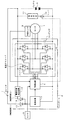
以下、図面を参照して本発明を詳細に説明する。図1は、本発明を適用した電源供給機構の実施形態を示すブロック図である。本実施形態の電源供給機構は、電動機、例えば永久磁石式ブラシレスモータ1を駆動するためのコントローラ2を備え、コントローラ2は、電源回路3、制御回路4および駆動回路5を有する。スイッチ7は、コントローラ2に電力を供給する電源スイッチとして機能し、このスイッチ7をオンするとバッテリ6からの電力がスイッチ7、ダイオード13および電源回路3を通して制御回路4に供給され、制御回路4が起動される。
【0015】
駆動回路5は、FETと転流ダイオードの対をブリッジ接続することにより構成される。制御回路4は、モータ1の回転角度を検出する角度センサ8の出力にしたがって駆動回路5のFETの通電を切り換え、さらに、出力指令用センサ9の出力にしたがってそれで指示されるモータ出力が得られるようにFETの電流値を制御する。リレー10および回生抵抗11は、モータ1が発電機として機能する時にバッテリ6が過充電されるのを防ぐためのものである。
【0016】
モータ1の電力供給ラインに接続された電源状態検出回路12は、電力供給ラインの電圧値に応じて制御回路4の起動を行う起動部として機能する。なお、ダイオード13、14は、逆流防止用のものである。
【0017】
まず、バッテリ6が搭載されている場合の本電源供給機構の動作について説明する。スイッチ7をオンすると、バッテリ6からの電力がスイッチ7、ダイオード13および電源回路3を通して制御回路4に供給され、制御回路4が起動する。制御回路4は、モータ1の回転角度を検出する角度センサ8の出力にしたがって駆動回路5のFETの通電を切り換え、さらに、搭乗者による操作を検出する出力指令用センサ9の出力にしたがってFETの電流値を制御し、出力指令用センサ9の出力で指示されるモータ出力が得られるようにする。この結果、モータ1は搭乗者による操作に従って回転駆動され、電動車両は走行する。
【0018】
電動車両が惰性で走行する時や下り坂を走行する時などは、モータ1は発電機として動作し、いわゆる回生動作が行われる。この回生動作時、モータ1により発電された電力は、駆動回路5の転流ダイオードを整流ダイオードとして整流されてバッテリ6に供給され、これを充電する。
【0019】
バッテリ6が満充電となって電力供給ラインの電圧が過電圧になると、制御回路4は、電力供給ラインの電圧安定化を行い、バッテリが過充電されないようにする。電動車両が惰性で走行したり、急な下り坂を走行するような場合にスイッチ7が意図的にオフにされても、電力供給ラインの過電圧が電源状態検出回路12により検出され、制御回路4には電源状態検出回路12、ダイオード14および電源回路3を通して電力が供給されて起動されるため、電力供給ラインの電圧安定化は継続して行われる。
【0020】
以上のように、スイッチ7がオフされていても、制御回路4は、電源状態検出回路12、ダイオード14および電源回路3を通して電力供給を受けて起動され、電力供給ラインの電圧安定化を行い、バッテリが過充電されないようにする。この電圧安定化は、駆動回路5のFETの電流を低下させ、弱め界磁を行うことによりモータ1の発電量を低減させることにより、あるいはリレー10をオンにして回生抵抗11を投入してこの回生抵抗11に電流を流すことにより、あるいはショートブレーキをかけることにより、あるいはこれらを組み合わせることにより実現できる。
【0021】
次に、バッテリ6が抜かれた場合の動作について説明する。この場合の電力供給ラインの電圧安定化の動作は、バッテリ6が搭載されている場合の動作と基本的には同じである。すなわち、バッテリ6が抜かれた状態で電動車両が惰性で走行したり、急な下り坂を走行するような時の電力供給ラインの過電圧は、電源状態検出回路12により検出され、制御回路4には電源状態検出回路12、ダイオード14および電源回路3を通して電力が供給される。
【0022】
これにより、バッテリ6が抜かれていても、制御回路4は、電源状態検出回路12を通る経路で電力供給を受けて起動され、電力供給ラインの電圧安定化を行い、過電圧発生からシステム構成部品が保護される。
【0023】
図2は、電源状態検出回路12の例を示す回路図である。本例は、電力供給ラインの電圧が一定値(過電圧)以上になった時、電源供給ラインを電源回路に接続する過電圧検出回路であり、トランジスタT1、T2、ツェナーダイオードZD1および抵抗R1、R2で構成される。過電圧設定値は、ほぼツェナーダイオードZD1のツェナー電圧値で規定される。
【0024】
電力供給ラインの電圧がツェナーダイオードZD1のツェナー電圧値でほぼ規定される過電圧設定値以上になるとこれがオンしてトランジスタT1がオンし、さらにトランジスタT2がオンして電力供給ラインを電源回路3に接続する。
【0025】
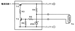
図3は、電源状態検出回路12の他の例を示す回路図である。本例は、電力供給ラインの電圧値およびバッテリ6の過充電状態に応じて電源供給ラインを電源回路に接続するバッテリ過充電検出回路であり、トランジスタT3、T4、ツェナーダイオードZD2、温度依存性抵抗などのバッテリ温度センサTHおよび抵抗R3〜R6で構成される。この回路によれば、トランジスタT3、したがってトランジスタT4がオンする電力供給ラインの電圧値を一定値とせずに、バッテリ6の温度によって変化させることができる。
【0026】
バッテリ6の過充電時には充電効率が低下してその温度が上昇し、バッテリ温度センサTHの抵抗値が小さくなるため、トランジスタT3、T4は、電力供給ラインの電圧値のより小さい値でオンする。このバッテリ過充電検出回路を用いることにより、電力供給ラインの過電圧およびバッテリの過充電を確実に防ぐことができる。なお、ツェナーダイオードZD2は、トランジスタT3やバッテリ温度センサTHに一定値以上の過電圧が加わらないようにする保護用のものである。
【0027】
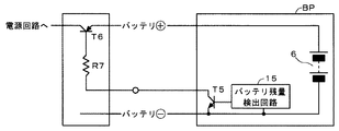
図4は、電源状態検出回路12のさらに他の例を示す回路図である。本例は、バッテリパックBPに組み込まれたバッテリ残量検出回路15を用いてバッテリ6の満充電状態を検出し、それに応じて電源供給ラインを電源回路3に接続するバッテリ満充電検出回路である。
【0028】
バッテリパックBPにはバッテリ6とともにバッテリ残量検出回路15、バッテリ残量検出回路15がバッテリ6の満充電状態を検出した時にオンとなるトランジスタT5が組み込まれている。ここでバッテリ残量検出回路15がバッテリ6の満充電状態を検出すると、トランジスタT5がオンとなり、トランジスタT5のコレクタに抵抗R7を介してベースが接続されているトランジスタT6がオンとなって電力供給ラインを電源回路3に接続する。なお、バッテリ6の残量は、バッテリ6の充電および放電を積算することにより検出することができる。
【0029】
なお、図2ないし図4の電源状態検出回路は、単独で用いることができるのはもちろん、それらを適宜組み合わせて用いることもできる。
【0030】
図5は、本発明を適用した電源供給機構の他の実施形態を示すブロック図であり、図1と同符号は同一または同等部分を表している。本実施形態は、スイッチ7がダイオード13を介してオートパワーオフ回路20に接続され、電源状態検出回路12がダイオード14を介してオートパワーオフ回路20に接続され、オートパワーオフ回路20の出力側が電源回路3の入力側に接続された点で異なっている。電源状態検出回路12は、モータ1の電力供給ラインの電圧値に応じて制御回路4の起動を行う起動部として機能する。
【0031】
ここで、オートパワーオフ回路20は、スイッチ7がオンされている場合において、所定の条件下で自動的に電源回路への電力供給を絶つものである。また、オートパワーオフ回路20は、オートパワーオフの状態において、電源状態検出回路12からの信号を入力すると、再び電源回路3に対して電力を供給する。
【0032】
バッテリ6が搭載されている場合、スイッチ7をオンすると、オートパワーオフ回路20は、それをトリガとして電源回路3に対して電力を供給し、電力供給ライン(バッテリの(+)側ライン)からスイッチ7、ダイオード13、オートパワーオフ回路20および電源回路3を通して供給される電力により制御回路4が起動する。制御回路4は、モータ1の回転角度を検出する角度センサ8の出力にしたがって駆動回路5のFETの通電を切り換え、さらに、搭乗者による操作を検出する出力指令用センサ9の出力にしたがってFETの電流値を制御し、出力指令用センサ9の出力で指示されるモータ出力が得られるようにする。
【0033】
電動車両が惰性で走行する時や下り坂を走行する時などは、モータ1は発電機として動作し、いわゆる回生動作が行われる。この回生動作時、モータ1により発電された電力は、駆動回路5を介してバッテリ6に供給され、これを充電する。
【0034】
スイッチ7がオンの状態で、電動車両がオートパワーオフの状況下にある場合、バッテリ6が満充電状態で、電動車両が惰性で走行したり、急な下り坂を走行したりすることにより電力供給ラインが過電圧になると、電源状態検出回路12はこれを検出してトリガ信号をオートパワーオフ回路20に出力する。
【0035】
すると、オートパワーオフ回路20は、電源回路3に対して電力を供給し、制御回路4は、電力供給ラインから電源状態検出回路12、ダイオード14およびオートパワーオフ回路20を通して電力供給を受けて起動され、電力供給ラインの電圧安定化を行う。
【0036】
これにより、スイッチ7がオンの状態で、電動車両がオートパワーオフの状況下にある場合、バッテリ6が満充電状態で、電動車両が惰性で走行したり、急な下り坂を走行したりしても、電力供給ラインに過電圧が発生しなくなり、バッテリ6の過充電が防止され、システム構成部品も過電圧等から保護される。
【0037】
なお、図5の実施形態の電圧状態検出回路12には、図2ないし図4に示した電圧状態検出回路やそれらの組み合わせを採用することができる。また、オートパワーオフ回路20は、スイッチ7がオフされている場合であっても電源状態検出回路12からの信号入力があった場合には自動的に電源回路3に対し電力を供給する構成としてもよい。
【0038】
図6は、本発明を適用できる電動スクータの一例を示す概略側面図である。同図において、車体フレーム50は、概ねメインフレーム51と、メインフレーム51から左右に分かれて後方に延びるサイドフレーム52とから構成されている。メインフレーム51の前端部にはヘッドパイプ53が結合され、ガセット54により補強されている。ヘッドパイプ53には回転自在に操向軸55が支持され、操向軸55の下端部にフロントフォーク56が結合されている。
【0039】
フロントフォーク56の下部には車軸57で支持された車輪が58Fが取り付けられ、上部にはハンドル59が設けられている。操向軸55、フロントフォーク56およびハンドル59は、操舵手段を構成する。
【0040】
フロントフォーク56の上部はフロントカバー60で覆われている。フロントカバー60の上方にはハンドルカバー61が設けられている。ハンドルカバー61から車体左右に向けてハンドル59のグリップ部分が突き出している。
【0041】
フロントカバー60の下部にセンタカバー62が結合されている。センタカバー62の後部にボディカバー63が結合されている。ボディカバー63の上方にはシート64が支持され、また、ボディカバー63によりパワーユニット65上方の車体後部が覆われている。パワーユニット65は、駆動装置としての電動機や変速機構を含んでいる。
【0042】
パワーユニット65に後輪58Rが支持されている。また、パワーユニット65とサイドフレーム52との間には上部取付ブラケット66を介してリアクッション67が取り付けられている。サイドフレーム52には取付パイプ68が結合され、取付パイプ68によりピボット軸69を介してパワーユニット65が支持されている。ボディカバー63後部にはナンバプレート取付部70およびテールランプ71が設けられている。
【0043】
メインフレーム51に下部にバッテリユニット72が配置され、ブラケット73、74で支持されているとともに、固定バンド75F、75R、75Cで前後および中央が固定されている。また、バッテリユニット72は、リッド76F、76Rで下部が覆われている。
【0044】
パワーユニット65は、ダクトチューブ77を通じる空気により空冷され、バッテリユニット72は、リアダクト78および排風機79を通じる空気により空冷される。
【0045】
バッテリユニット71からの電力が適宜箇所に配置された電源供給機構を介してパワーユニット65の電動機に供給される。なお、電源供給機構に対する出力指令は、ハンドル59に設けられているスロットルグリップの操作に従って出力される。
【0046】
本発明は、出力指令用センサ9を踏力センサとすることによりアシスト自転車にも適用することができる。図7は、本発明を適用できるアシスト自転車の一例の概略側面図である。
【0047】
アシスト自転車の車体フレーム101は、車体前方に位置するヘッドパイプ102と、ヘッドパイプ102から後下がりに延びるダウンパイプ103と、ダウンパイプ103に連結されて後方に延びるリヤフォーク104と、ダウンパイプ103の最下端から上方に立ち上がるシートポスト105とを備えている。
【0048】
ヘッドパイプ102にはフロントフォーク106が回動自在に支持されている。フロントフォーク106の下端には前輪107が軸支され、フロントフォーク106の上端には操向ハンドル108が取り付けられている。操向ハンドル108にはブレーキレバー109が設けられ、ブレーキレバー109から引き出されるケーブル110は、フロントフォーク106に固定された前輪ブレーキ111に連結されている。後輪ブレーキ用のブレーキレバーも操向ハンドル108に設けられているが、図示は省略している。ブレーキレバー109には、このブレーキレバーが操作されたことを感知するブレーキセンサ(図示せず)が設けられている。
【0049】
シートポスト105の上端に連結される左右一対のステー112は後下がりに延び、下端近傍でリヤフォーク104と結合されている。リヤフォーク104とステー112とが結合されてなる部材には後輪113の変速機内装シリンダ130が支持され、さらに前記部材に支持されて変速機内装シリンダ130と同軸上に補助動力源としてのモータ114が設けられている。モータ114は、例えば発電機としても機能させることができる永久磁石式ブラシレスモータである。
【0050】
シートポスト105には、上端にシート115を備えた支持軸116が、シート115の高さを調整可能に装着されている。シート115の下方でシートポスト105と後輪113との間にはモータ114に電力を供給するバッテリ117が設けられている。バッテリ117は、シートポスト105に固着されるブラケット118に保持されている。ブラケット118には給電部119が設けられ、この給電部119は、図示しない電線でモータ114に結合されるとともに、バッテリ117の電極に接続されている。バッテリ117の上部は、バンド120とバックル金具121とからなる締結具でシートポスト105に支持されている。
【0051】
ダウンパイプ103とシートポスト105との交差部には、車体の左右に延びるクランク軸122が支持され、クランク軸122には、クランク123を介してペダル124が結合されている。クランク軸122には図示しない踏力センサを介して駆動スプロケット125が連結され、ペダル124に加えられた踏力は踏力センサを介して駆動スプロケット125に伝達される。駆動スプロケット125と後輪113のハブに設けられた従動スプロケット126間にはチェーン127が掛け渡されている。チェーン127の張り側および駆動スプロケット125はチェーンカバー128で覆われている。クランク軸122には、クランク軸122の回転センサが設けられている。
【0052】
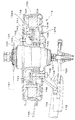
図8は、モータ114の断面図である。リヤフォーク104の後端およびステー112の下端の接合部から後方に張り出したプレート129には、変速機内装シリンダ130が軸131で支持されている。変速機内装シリンダ130の外周にはホイールハブ132が嵌合されている。ホイールハブ132は内筒および外筒を有する環状体であり、内筒の内周面が変速機内装シリンダ130の外周に当接している。ホイールハブ132の側面には、変速機内装シリンダ130から張り出した連結板133がボルト134によって固定されている。ホイールハブ132の外筒の内周にはモータ114のロータ側磁極を構成するネオジウム磁石135が所定間隔をおいて配置されている。すなわち外筒は磁石135を保持するロータコアを構成している。
【0053】
ホイールハブ132の内筒の外周には軸受136が嵌合し、この軸受136の外周にはステータ支持板137が嵌合している。ステータ支持板137の外周にはステータ138が配置され、ボルト140によって取り付けられている。ステータ138はロータコアつまりホイールハブ132の外筒と所定の間隙を有するように配置され、このステータ138には、三相コイル139が巻装されている。
【0054】
ステータ支持板137の側面には、光センサ141が設けられている。光センサ141はホイールハブ132が回転したときに、このホイールハブ132に設けられたリング状部材によって光路が断続的に遮断され、その結果、パルス波形信号を出力する。リング状部材142は回転時に光センサ141の光路を断続的に遮断できるよう、規則的な矩形歯形状を有している。前記パルス波形信号に基づいてロータとしてのホイールハブ132の位置信号が検出される。光センサ141はモータ114の各相に対応して3カ所に設けられ、モータ114の磁極センサおよび回転センサとして機能している。
【0055】
また、ステータ支持板137の側面には、制御基板143が設けられ、磁極センサとしての光センサ141からの位置信号にしたがって三相コイル139への通電制御を行う。この制御基板143上にはCPUやFET等の制御素子が装着されている。なお、制御基板143は光センサ141用の取り付け基板と一体化できる。
【0056】
ホイールハブ132の外周には図示しない後輪のリムと連結されるスポーク144が固着されている。さらに、ステータ支持板137の、制御基板143等が装着された側とは反対側には、ボルト145によってブラケット146が固定され、ブラケット146は車体フレームのプレート129に図示しないボルトで結合されている。
【0057】
ホイールハブ132には、透明樹脂(クリアレンズ)132Aがはめ込まれた窓が設けられ、ステータ支持板137に固定された固定カバー137Aにも同様にクリアレンズ137Bがはめ込まれた窓が設けられている。
【0058】
このように、後輪113の軸131と同軸上に配置したステータとロータとからなる三相ブラシレスモータ114が設けられ、チェーン127、従動スプロケット126および変速機内装シリンダ130とによって伝達される人力に付加される補助動力を発生する。なお、モータ114は、前輪に設けることもできる。
【0059】
図9は、モータ114の出力制御回路図である。同図において、モータ114は、三相のステータコイル139を有し、駆動回路としてのインバータ147はステータコイル139に接続された6個のFET148a〜148fおよび転流ダイオード149a〜149fを有する。モータ114は、バッテリ117を駆動用電源としている。
【0060】
制御回路150は、電源回路151を通して供給される電力で起動され、踏力センサ152の出力を入力として現在の踏力に応じたモータ駆動力にすべくFET148a〜148fを通電制御する。なお、この通電制御をさらに車速センサ153が検出する車速に応じて行うようにすることもできる。モータ114のロータが回転することによりステータコイル139に発生された回生電力は、インバータ147の転流ダイオード149a〜149fを整流ダイオードとして整流されてバッテリ117に供給され、これを充電する。
【0061】
本発明は、図6ないし図9で示した電動スクータやアシスト自転車に限らず、その他の電動車両にも適用して、バッテリからの電力が制御手段に供給されない場合やバッテリが抜かれた場合に対して配慮することができる。
【0062】
なお、電力供給ラインの電圧が一定値以上であるときにのみ制御手段に電力を供給してこれを起動するようにすれば、省エネの効果も得ることができ、この起動のために電力供給ラインの電圧が一定値以上でオンするツェナーダイオードを使用した図2の電源状態検出回路を採用すれば、より省エネの効果を高めることができる。また、以上では、電動機としてブラシレスモータを用いる例について説明したが、回生動作などにおいて同様の機能を持つものであればブラシモータを用いることもできる。
【0063】
【発明の効果】
以上の説明から明らかなように、本発明によれば、バッテリからの電力が制御手段に供給されない場合やバッテリが抜かれた場合であっても電動機によって発生される電力供給ラインの電圧を安定化することができ、バッテリの過充電や過電圧発生を防止することができるとともにシステム構成部品を過電圧等から保護することができる。
【図面の簡単な説明】
【図1】 本発明を適用した電源供給機構の実施形態を示すブロック図である。
【図2】 電源状態検出回路の例を示す回路図である。
【図3】 電源状態検出回路の他の例を示す回路図である。
【図4】 電源状態検出回路のさらに他の例を示す回路図である。
【図5】 本発明を適用した電源供給機構の他の実施形態を示すブロック図である。
【図6】 本発明を適用できる電動スクータの一例を示す概略側面図である。
【図7】 本発明を適用できるアシスト自転車の一例を示す概略側面図である。
【図8】 図7のモータの断面図である。
【図9】 図7のモータの出力制御回路図である。
【符号の説明】
1、114・・・モータ、2・・・コントローラ、3、151・・・電源回路、4、150・・・制御回路、5、147・・・駆動回路、6、117・・・バッテリ、7・・・スイッチ、8・・・角度センサ、9・・・出力指令用センサ、10・・・リレー、11・・・回生抵抗、12・・・電源状態検出回路、13、14・・・ダイオード、15・・・バッテリ残量検出回路、20・・・オートパワーオフ回路、50・・・車体フレーム、51・・・メインフレーム、52・・・サイドフレーム、53・・・ヘッドパイプ、55・・・操向軸、56・・・フロントフォーク、58F、58R・・・車輪、59・・・ハンドル、60・・・フロントカバー、64・・・シート、65・・・パワーユニット、67・・・リアクッション、72・・・バッテリユニット、101・・・車体フレーム、105・・・シートポスト、108・・・操向ハンドル、109・・・ブレーキレバー、122・・・クランク軸、124・・・ペダル、127・・・チェーン、132・・・ホイールハブ(アウタロータ)、135・・・永久磁石、137・・・ステータ支持板、138・・・ステータコア、139・・・ステータコイル、141・・・光センサ、143・・・基板、148a〜148f・・・FET、149a〜149f・・・転流ダイオード、152・・・踏力センサ、153・・・車速センサ、T1〜T6・・・トランジスタ、ZD1、ZD2・・・ツェナーダイオード、TH・・・バッテリ温度センサ、R1〜R7・・・抵抗器[0001]
BACKGROUND OF THE INVENTION
The present invention relates to a power supply mechanism in an electric vehicle such as an electric scooter, and particularly generated by an electric motor even when power is not supplied from the battery to a control means for controlling the driving of the electric motor or when the battery is removed. The present invention relates to a power supply mechanism in an electric vehicle that can stabilize the voltage of a power supply line, prevent battery overcharge and overvoltage generation, and protect system components from overvoltage and the like.
[0002]
[Prior art]
The electric scooter is equipped with an electric motor for rotating the axle, for example, a permanent magnet brushless motor, or a power supply mechanism that receives electric power from a battery and drives the electric motor. This power supply mechanism has a regenerative function that uses an electric motor as a generator when the electric scooter travels by inertia or travels downhill, and charges the battery with the electric power generated thereby. The power supply mechanism also has a function of performing control to stabilize the voltage of the power supply line that supplies power to the electric motor.
[0003]
As a device for preventing an overload of a power supply device mounted on a vehicle, there is a vehicle power supply protection circuit described in Japanese Patent Laid-Open No. 5-49101. In this vehicle power supply protection circuit, the control device controls power supply to the load in accordance with the state of the battery terminal voltage. That is, the terminal voltage of the battery charged by the regenerative power of the rotating machine operating as a starter is monitored by the control circuit, and if it exceeds the reference value, the power from the battery is loaded via the inverter circuit ( When the terminal voltage of the battery is below the reference value, the operation of the inverter circuit is stopped to prevent overdischarge of the battery.
[0004]
[Problems to be solved by the invention]
By the way, in an electric vehicle, when the battery is removed or the vehicle is traveling on a long downhill, a switch for supplying electric power from the battery to the electric motor may be intentionally cut. In such a case, voltage stabilization of the power supply line is not performed, and it is difficult to protect components (such as FETs) constituting the power supply mechanism due to the high voltage of the power supply line.
[0005]
In the vehicle power supply protection circuit described in Japanese Patent Application Laid-Open No. 5-49101, the control circuit is configured so that power is always supplied from the battery, and the case where the battery is removed or the switch is disconnected. The configuration is not as expected. Therefore, even if the configuration described in the above publication is applied to an electric vehicle, it is difficult to solve the above problem.
[0006]
From the above, even when the battery installed in the electric vehicle is removed or the vehicle is driven with the switch turned off, the voltage of the power supply line is stabilized so that no overvoltage occurs in the power supply line A power supply mechanism for an electric vehicle is desired.
[0007]
The present invention is considered in view of the above circumstances, and stabilizes the voltage of the power supply line generated by the electric motor even when power from the battery is not supplied to the control means or when the battery is removed. An object of the present invention is to provide a power supply mechanism in an electric vehicle that can protect system components from battery overcharge and overvoltage generation.
[0008]
[Means for Solving the Problems]
In order to solve the above-described problems, the present invention includes a driving unit that drives an electric motor and a control unit that controls the driving unit, and uses the electric motor as a generator to supply regenerative power to a power supply line of the electric motor. In a power supply mechanism in an electric vehicle having a regenerative function, an activation unit that activates the control unit by supplying power from the power supply line to the control unit according to a voltage value of the power supply line of the motor; Voltage stabilization means for stabilizing the voltage of the power supply line according to an instruction from the control means, The control means is activated by the electric power when the power is supplied from the battery and controls the driving means. When the electric power is not supplied from the battery, the control means uses the regeneration function to When the regenerative power supplied through the power supply line exceeds a predetermined value, it is activated via the activation unit to control the driving means. The point has the first feature.
[0009]
In the present invention, the voltage stabilization means is a regenerative resistor provided via a switch between the power supply line and the ground line, and the control means performs opening / closing control of the switch. There is a second feature.
[0010]
Further, the present invention is characterized in that the voltage stabilizing means is the driving means, and the control means controls the driving means so as to stabilize the voltage of the power supply line. is there.
[0011]
According to the first feature, even when power from the battery is not supplied to the control means or when the battery is removed, the control means is activated by the activation means. Therefore, even in such a case, the voltage of the power supply line generated by the electric motor can be stabilized, and the system components can be protected from the occurrence of overvoltage.
[0012]
Further, according to the second feature, the control means can stabilize the voltage of the power supply line by closing the switch and turning on the regenerative resistor.
[0013]
Further, according to the third feature, the control unit can stabilize the voltage of the power supply line by controlling the driving unit so as to stabilize the voltage of the power supply line.
[0014]
DETAILED DESCRIPTION OF THE INVENTION
Hereinafter, the present invention will be described in detail with reference to the drawings. FIG. 1 is a block diagram showing an embodiment of a power supply mechanism to which the present invention is applied. The power supply mechanism of this embodiment includes a
[0015]
The drive circuit 5 is configured by bridge-connecting a pair of FET and commutation diode. The control circuit 4 switches the energization of the FET of the drive circuit 5 in accordance with the output of the
[0016]
The power supply
[0017]
First, the operation of the power supply mechanism when the
[0018]
When the electric vehicle travels by inertia or when traveling on a downhill, the motor 1 operates as a generator, and a so-called regenerative operation is performed. During this regenerative operation, the electric power generated by the motor 1 is rectified using the commutation diode of the drive circuit 5 as a rectifier diode and supplied to the
[0019]
When the
[0020]
As described above, even when the switch 7 is turned off, the control circuit 4 is activated by receiving power supply through the power supply
[0021]
Next, the operation when the
[0022]
As a result, even if the
[0023]
FIG. 2 is a circuit diagram illustrating an example of the power supply
[0024]
When the voltage of the power supply line becomes equal to or higher than the overvoltage set value almost defined by the Zener voltage value of the Zener diode ZD1, this is turned on, the transistor T1 is turned on, and the transistor T2 is turned on to connect the power supply line to the
[0025]
FIG. 3 is a circuit diagram showing another example of the power supply
[0026]
When the
[0027]
FIG. 4 is a circuit diagram showing still another example of the power supply
[0028]
The battery pack BP incorporates the
[0029]
It should be noted that the power supply state detection circuits in FIGS. 2 to 4 can be used alone or in combination as appropriate.
[0030]
FIG. 5 is a block diagram showing another embodiment of a power supply mechanism to which the present invention is applied. The same reference numerals as those in FIG. 1 denote the same or equivalent parts. In the present embodiment, the switch 7 is connected to the auto power off
[0031]
Here, the auto power-
[0032]
When the
[0033]
When the electric vehicle travels by inertia or when traveling on a downhill, the motor 1 operates as a generator, and a so-called regenerative operation is performed. During this regenerative operation, the electric power generated by the motor 1 is supplied to the
[0034]
When the switch 7 is on and the electric vehicle is in an auto power-off state, the
[0035]
Then, the auto power-
[0036]
As a result, when the switch 7 is on and the electric vehicle is in an auto power off state, the
[0037]
The voltage
[0038]
FIG. 6 is a schematic side view showing an example of an electric scooter to which the present invention can be applied. In the figure, a
[0039]
A
[0040]
An upper portion of the
[0041]
A
[0042]
The
[0043]
A
[0044]
The
[0045]
The electric power from the
[0046]
The present invention can also be applied to an assist bicycle by using the
[0047]
The
[0048]
A
[0049]
A pair of left and right stays 112 connected to the upper end of the
[0050]
A
[0051]
A
[0052]
FIG. 8 is a cross-sectional view of the
[0053]
A
[0054]
An
[0055]
Further, a
[0056]
[0057]
The
[0058]
Thus, a three-
[0059]
FIG. 9 is an output control circuit diagram of the
[0060]
The
[0061]
The present invention is not limited to the electric scooters and assist bicycles shown in FIGS. 6 to 9 but is also applied to other electric vehicles. For the case where the power from the battery is not supplied to the control means or the battery is removed. Can be considered.
[0062]
In addition, if power is supplied to the control means and activated only when the voltage of the power supply line is equal to or higher than a certain value, an energy saving effect can be obtained. If the power supply state detection circuit of FIG. 2 using a Zener diode that is turned on when the voltage of the voltage is above a certain value is employed, the energy saving effect can be further enhanced. Moreover, although the example which uses a brushless motor as an electric motor was demonstrated above, a brush motor can also be used if it has the same function in regenerative operation etc.
[0063]
【The invention's effect】
As is apparent from the above description, according to the present invention, the voltage of the power supply line generated by the electric motor is stabilized even when power from the battery is not supplied to the control means or when the battery is removed. Thus, overcharging of the battery and occurrence of overvoltage can be prevented, and system components can be protected from overvoltage and the like.
[Brief description of the drawings]
FIG. 1 is a block diagram showing an embodiment of a power supply mechanism to which the present invention is applied.
FIG. 2 is a circuit diagram illustrating an example of a power supply state detection circuit.
FIG. 3 is a circuit diagram showing another example of a power supply state detection circuit.
FIG. 4 is a circuit diagram showing still another example of a power supply state detection circuit.
FIG. 5 is a block diagram showing another embodiment of a power supply mechanism to which the present invention is applied.
FIG. 6 is a schematic side view showing an example of an electric scooter to which the present invention can be applied.
FIG. 7 is a schematic side view showing an example of an assist bicycle to which the present invention can be applied.
8 is a cross-sectional view of the motor of FIG.
FIG. 9 is an output control circuit diagram of the motor of FIG.
[Explanation of symbols]
DESCRIPTION OF SYMBOLS 1,114 ... Motor, 2 ... Controller, 3, 151 ... Power supply circuit, 4, 150 ... Control circuit, 5, 147 ... Drive circuit, 6, 117 ... Battery, 7 ... Switch, 8 ... Angle sensor, 9 ... Output command sensor, 10 ... Relay, 11 ... Regenerative resistor, 12 ... Power supply state detection circuit, 13, 14 ...
Claims (3)
前記電動機の電力供給ラインの電圧値に応じて該電源供給ラインから前記制御手段に電力を供給して該制御手段を起動する起動部と、
前記制御手段からの指示に応じて前記電力供給ラインの電圧を安定化する電圧安定化手段とを備え、
前記制御手段は、バッテリからの電力の供給が行われる場合には、該電力により起動されて前記駆動手段を制御し、バッテリからの電力の供給が行われない場合には、前記回生機能により前記電源供給ラインを通して供給される回生電力が所定値を越えたときに前記起動部を介して起動されて前記駆動手段を制御することを特徴とする電動車両における電源供給機構。A power supply mechanism in an electric vehicle having a regenerative function for supplying regenerative power to a power supply line of the motor using a drive means for driving the motor and a control means for controlling the drive means, using the motor also as a generator In
An activating unit that activates the control unit by supplying power to the control unit from the power supply line according to the voltage value of the power supply line of the motor;
Voltage stabilization means for stabilizing the voltage of the power supply line in accordance with an instruction from the control means,
The control means is activated by the electric power when the power is supplied from the battery and controls the driving means. When the electric power is not supplied from the battery, the control means uses the regeneration function to A power supply mechanism in an electric vehicle, which is activated via the activation unit and controls the drive means when regenerative power supplied through a power supply line exceeds a predetermined value .
Priority Applications (6)
| Application Number | Priority Date | Filing Date | Title |
|---|---|---|---|
| JP2002249310A JP3919002B2 (en) | 2002-08-28 | 2002-08-28 | Power supply mechanism for electric vehicles |
| TW092122384A TWI261555B (en) | 2002-08-28 | 2003-08-14 | Power supply apparatus for electric vehicle |
| CNB031539793A CN1295095C (en) | 2002-08-28 | 2003-08-21 | Power source supply mechanism for electric vehicle |
| IT000651A ITTO20030651A1 (en) | 2002-08-28 | 2003-08-22 | POWER SUPPLY SYSTEM IN AN ELECTRIC VEHICLE. |
| FR0350448A FR2843921B1 (en) | 2002-08-28 | 2003-08-22 | APPARATUS FOR POWER SUPPLY IN AN ELECTRIC VEHICLE |
| US10/646,697 US7082018B2 (en) | 2002-08-28 | 2003-08-25 | Power supply apparatus in electric vehicle |
Applications Claiming Priority (1)
| Application Number | Priority Date | Filing Date | Title |
|---|---|---|---|
| JP2002249310A JP3919002B2 (en) | 2002-08-28 | 2002-08-28 | Power supply mechanism for electric vehicles |
Publications (2)
| Publication Number | Publication Date |
|---|---|
| JP2004088961A JP2004088961A (en) | 2004-03-18 |
| JP3919002B2 true JP3919002B2 (en) | 2007-05-23 |
Family
ID=31712248
Family Applications (1)
| Application Number | Title | Priority Date | Filing Date |
|---|---|---|---|
| JP2002249310A Expired - Fee Related JP3919002B2 (en) | 2002-08-28 | 2002-08-28 | Power supply mechanism for electric vehicles |
Country Status (6)
| Country | Link |
|---|---|
| US (1) | US7082018B2 (en) |
| JP (1) | JP3919002B2 (en) |
| CN (1) | CN1295095C (en) |
| FR (1) | FR2843921B1 (en) |
| IT (1) | ITTO20030651A1 (en) |
| TW (1) | TWI261555B (en) |
Cited By (2)
| Publication number | Priority date | Publication date | Assignee | Title |
|---|---|---|---|---|
| TWI677455B (en) * | 2017-09-08 | 2019-11-21 | 日商新電元工業股份有限公司 | Electric vehicle, electric vehicle control device and electric vehicle control method |
| US10629962B2 (en) | 2017-05-12 | 2020-04-21 | Hyundai Motor Company | Vehicular battery module |
Families Citing this family (26)
| Publication number | Priority date | Publication date | Assignee | Title |
|---|---|---|---|---|
| US6917179B2 (en) * | 2001-10-25 | 2005-07-12 | Toyota Jidosha Kabushiki Kaisha | Load driver and control method for safely driving DC load and computer-readable recording medium with program recorded thereon for allowing computer to execute the control |
| JP4121511B2 (en) * | 2004-03-30 | 2008-07-23 | 三洋電機株式会社 | Power supply |
| JP4378224B2 (en) * | 2004-06-04 | 2009-12-02 | 株式会社ミクニ | Power supply |
| US7332881B2 (en) * | 2004-10-28 | 2008-02-19 | Textron Inc. | AC drive system for electrically operated vehicle |
| CN1861445B (en) * | 2004-10-28 | 2012-07-04 | 特克斯特朗创新有限公司 | Ac drive system for electrically operated vehicle |
| US7750501B2 (en) * | 2005-10-27 | 2010-07-06 | Continental Automotive Systems Us, Inc. | System and method of over voltage control for a power system |
| JP4972377B2 (en) * | 2006-10-23 | 2012-07-11 | 日立オートモティブシステムズ株式会社 | Electric brake control device and electric brake device |
| US20080164106A1 (en) * | 2007-01-04 | 2008-07-10 | Textron Inc. | Electric Brake for Utility Vehicles |
| US20080211438A1 (en) * | 2007-03-02 | 2008-09-04 | Textron Inc. | Fully Charged Battery Protection |
| US7926889B2 (en) * | 2007-10-29 | 2011-04-19 | Textron Innovations Inc. | Hill hold for an electric vehicle |
| US20100244776A1 (en) * | 2008-12-25 | 2010-09-30 | Steven Leonard | Magnetic Motor |
| EP2394837B8 (en) * | 2009-02-09 | 2016-12-21 | Toyota Jidosha Kabushiki Kaisha | Power supply system and electric vehicle using the same |
| JP5404435B2 (en) * | 2010-01-13 | 2014-01-29 | 本田技研工業株式会社 | Electric vehicle regenerative charge control device |
| US9434362B2 (en) * | 2010-03-29 | 2016-09-06 | Current Motor Company | System and method to control regenerative braking |
| JP5564389B2 (en) * | 2010-09-30 | 2014-07-30 | 本田技研工業株式会社 | Control device for battery-assisted bicycle |
| CN103442935B (en) * | 2011-03-31 | 2015-11-25 | 本田技研工业株式会社 | Control mechanism for electric vehicle |
| CN102501772B (en) * | 2011-10-29 | 2014-04-23 | 苏州海格新能源汽车电控系统科技有限公司 | Brake feedback control circuit and method of electric vehicle |
| JP5525505B2 (en) * | 2011-11-14 | 2014-06-18 | 本田技研工業株式会社 | Electric vehicle power supply device |
| CN104507756B (en) * | 2012-07-27 | 2016-08-24 | 日产自动车株式会社 | The control device of vehicle and the control method of vehicle |
| DE102013204784B4 (en) * | 2013-03-19 | 2018-01-11 | Robert Bosch Gmbh | Electric vehicle axle device |
| CN103522916A (en) * | 2013-10-31 | 2014-01-22 | 济南宏昌车辆有限公司 | Double power sources switching control system of electric car |
| KR101369614B1 (en) * | 2013-12-10 | 2014-03-04 | 장석호 | Wheel having motor means serves as power generator having power assistance structure of multiple |
| WO2016041601A1 (en) * | 2014-09-19 | 2016-03-24 | Höganäs Ab | An electric machine assembly |
| CN104999917B (en) * | 2015-04-27 | 2017-06-09 | 长安大学 | Failure monitor device when a kind of motor in electric automobile is braked |
| EP3308993A1 (en) * | 2016-09-30 | 2018-04-18 | Taiyo Yuden Co., Ltd. | Motor driving control apparatus and electrically assisted vehicle |
| JP7279302B2 (en) * | 2018-04-06 | 2023-05-23 | 三菱自動車工業株式会社 | vehicle activation system |
Family Cites Families (6)
| Publication number | Priority date | Publication date | Assignee | Title |
|---|---|---|---|---|
| US3989990A (en) * | 1974-05-31 | 1976-11-02 | Westinghouse Electric Corporation | Feedback field control for an electric vehicle |
| GB2112233B (en) * | 1981-12-23 | 1986-06-11 | Gen Electric | Electric vehicle current regulator |
| US4950972A (en) * | 1988-12-14 | 1990-08-21 | Texas Instruments Incorporated | Alternator system for automotive vehicles |
| JPH0549101A (en) * | 1991-08-05 | 1993-02-26 | Hino Motors Ltd | Power supply protective circuit for vehicle |
| JPH06105405A (en) * | 1992-09-18 | 1994-04-15 | Hitachi Ltd | Brake controller for electric motor vehicle |
| DE69628637T2 (en) * | 1995-09-18 | 2004-04-29 | Seiko Epson Corp. | SECURITY MECHANISM FOR AN ELECTRIC VEHICLE |
-
2002
- 2002-08-28 JP JP2002249310A patent/JP3919002B2/en not_active Expired - Fee Related
-
2003
- 2003-08-14 TW TW092122384A patent/TWI261555B/en not_active IP Right Cessation
- 2003-08-21 CN CNB031539793A patent/CN1295095C/en not_active Expired - Fee Related
- 2003-08-22 IT IT000651A patent/ITTO20030651A1/en unknown
- 2003-08-22 FR FR0350448A patent/FR2843921B1/en not_active Expired - Fee Related
- 2003-08-25 US US10/646,697 patent/US7082018B2/en not_active Expired - Fee Related
Cited By (2)
| Publication number | Priority date | Publication date | Assignee | Title |
|---|---|---|---|---|
| US10629962B2 (en) | 2017-05-12 | 2020-04-21 | Hyundai Motor Company | Vehicular battery module |
| TWI677455B (en) * | 2017-09-08 | 2019-11-21 | 日商新電元工業股份有限公司 | Electric vehicle, electric vehicle control device and electric vehicle control method |
Also Published As
| Publication number | Publication date |
|---|---|
| CN1295095C (en) | 2007-01-17 |
| FR2843921B1 (en) | 2019-07-05 |
| US7082018B2 (en) | 2006-07-25 |
| US20040056616A1 (en) | 2004-03-25 |
| TW200405864A (en) | 2004-04-16 |
| CN1486885A (en) | 2004-04-07 |
| ITTO20030651A1 (en) | 2004-02-29 |
| JP2004088961A (en) | 2004-03-18 |
| TWI261555B (en) | 2006-09-11 |
| FR2843921A1 (en) | 2004-03-05 |
Similar Documents
| Publication | Publication Date | Title |
|---|---|---|
| JP3919002B2 (en) | Power supply mechanism for electric vehicles | |
| EP0901931B1 (en) | Motor controlling apparatus for a hybrid car | |
| EP2484581B1 (en) | Sports type, saddle type electric vehicle | |
| JP2002356190A (en) | Power-assisted bicycle | |
| JP3888681B2 (en) | Power supply device for electric vehicle | |
| JP4124447B2 (en) | Engine driven work machine | |
| JP3345288B2 (en) | Electric vehicle control device | |
| JP2006123595A (en) | Snowmobile | |
| JPH0583863A (en) | Charger for motor-driven vehicle | |
| JP4573280B2 (en) | Electric assist bicycle | |
| JP4124411B2 (en) | Electric assist bicycle regenerative control device | |
| KR100917586B1 (en) | Hybrid bicycle | |
| EP3407482B1 (en) | Engine-equipped vehicle | |
| Raghunath | Hardware design considerations for an electric bicycle using a BLDC motor | |
| JPH07111710A (en) | Hybrid power supply for motor running vehicle | |
| JP6823159B2 (en) | Vehicle engine control | |
| EP3301282B1 (en) | Vehicle | |
| JPH07149183A (en) | Control circuit for headlight of snowmobile | |
| JP2001122186A (en) | Control method for vehicle with motor assist function and device therefor | |
| JPH0678408A (en) | Electric circuit equipment for electric vehicle | |
| JP3835200B2 (en) | Theft prevention method for electric assist type bicycle | |
| JPH10323079A (en) | Motor drive equipment | |
| JP3155313B2 (en) | Regenerative braking control device for electric vehicles | |
| US20220185144A1 (en) | Battery charging system for a hybrid electric vehicle | |
| WO2018047128A1 (en) | A hybrid vehicle |
Legal Events
| Date | Code | Title | Description |
|---|---|---|---|
| A621 | Written request for application examination |
Free format text: JAPANESE INTERMEDIATE CODE: A621 Effective date: 20041202 |
|
| A977 | Report on retrieval |
Free format text: JAPANESE INTERMEDIATE CODE: A971007 Effective date: 20060426 |
|
| A131 | Notification of reasons for refusal |
Free format text: JAPANESE INTERMEDIATE CODE: A131 Effective date: 20060517 |
|
| A521 | Request for written amendment filed |
Free format text: JAPANESE INTERMEDIATE CODE: A523 Effective date: 20060712 |
|
| A131 | Notification of reasons for refusal |
Free format text: JAPANESE INTERMEDIATE CODE: A131 Effective date: 20061115 |
|
| A521 | Request for written amendment filed |
Free format text: JAPANESE INTERMEDIATE CODE: A523 Effective date: 20070110 |
|
| TRDD | Decision of grant or rejection written | ||
| A01 | Written decision to grant a patent or to grant a registration (utility model) |
Free format text: JAPANESE INTERMEDIATE CODE: A01 Effective date: 20070207 |
|
| A61 | First payment of annual fees (during grant procedure) |
Free format text: JAPANESE INTERMEDIATE CODE: A61 Effective date: 20070207 |
|
| R150 | Certificate of patent or registration of utility model |
Ref document number: 3919002 Country of ref document: JP Free format text: JAPANESE INTERMEDIATE CODE: R150 Free format text: JAPANESE INTERMEDIATE CODE: R150 |
|
| FPAY | Renewal fee payment (event date is renewal date of database) |
Free format text: PAYMENT UNTIL: 20100223 Year of fee payment: 3 |
|
| FPAY | Renewal fee payment (event date is renewal date of database) |
Free format text: PAYMENT UNTIL: 20110223 Year of fee payment: 4 |
|
| FPAY | Renewal fee payment (event date is renewal date of database) |
Free format text: PAYMENT UNTIL: 20110223 Year of fee payment: 4 |
|
| FPAY | Renewal fee payment (event date is renewal date of database) |
Free format text: PAYMENT UNTIL: 20120223 Year of fee payment: 5 |
|
| FPAY | Renewal fee payment (event date is renewal date of database) |
Free format text: PAYMENT UNTIL: 20130223 Year of fee payment: 6 |
|
| FPAY | Renewal fee payment (event date is renewal date of database) |
Free format text: PAYMENT UNTIL: 20130223 Year of fee payment: 6 |
|
| FPAY | Renewal fee payment (event date is renewal date of database) |
Free format text: PAYMENT UNTIL: 20140223 Year of fee payment: 7 |
|
| LAPS | Cancellation because of no payment of annual fees |