JP3916863B2 - Data center security equipment - Google Patents
Data center security equipment Download PDFInfo
- Publication number
- JP3916863B2 JP3916863B2 JP2000320985A JP2000320985A JP3916863B2 JP 3916863 B2 JP3916863 B2 JP 3916863B2 JP 2000320985 A JP2000320985 A JP 2000320985A JP 2000320985 A JP2000320985 A JP 2000320985A JP 3916863 B2 JP3916863 B2 JP 3916863B2
- Authority
- JP
- Japan
- Prior art keywords
- room
- key
- tenant
- small
- door
- Prior art date
- Legal status (The legal status is an assumption and is not a legal conclusion. Google has not performed a legal analysis and makes no representation as to the accuracy of the status listed.)
- Expired - Fee Related
Links
Images


Description
【0001】
【発明の属する技術分野】
この発明は、複数のテナントのサーバを共同部屋に設置したデータセンタを警備する装置に関するものである。
【0002】
【従来の技術】
近年インタネットプロバイダのサーバをテナントとして設置するデータセンタが増加している。したがって、各サーバは隣接して配置されている。
【0003】
【発明が解決しようとする課題】
上記のような従来のデータセンタでは、一つの部屋に多数のサーバが配置されており、物理的な防犯設備はまったく考慮されていないため、侵入者による情報の盗難の機会が多くなるという問題点がある。また、サーバを収容するラックのキーを持ち出して複製されることを防止できないという問題点もある。
【0004】
この発明は上記問題点を解消するためになされたもので、侵入者による情報の盗難、ラックのキーの持ち出し等の機会を減らすことができるようにしたデータセンタの警備装置を提供することを目的とする。
【0005】
【課題を解決するための手段】
この発明の第一発明に係るデータセンタの警備装置は、部屋の中にテナントに対応する複数の小室を設置し、この小室に対応するテナントが部屋内に不在であることが検出され、かつこのテナントに対応する小室の開扉状態が検出されると、異常警報を出力するようにしたものである。
【0006】
また、第2発明に係るデータセンタの警備装置は、部屋の中にテナントに対応する複数の小室を設置し、この小室の扉を開閉するキーを収納するキー保管箱を設け、このキー保管箱に対応する小室の扉が開くと異常警報を出力するようにしたものである。
【0007】
また、第3発明に係るデータセンタの警備装置は、部屋の中にテナントに対応する複数の小室を設置し、この小室の扉を開閉するキーを収納するキー保管箱を設け、小室に対応するテナントが不在であることが検出されたとき、キー保管箱にテナントに対応するキーが収納されていないか、又は、テナントに対応する小室の扉が開いていると異常警報を出力するようにしたものである。
【0008】
また、第4発明に係るデータセンタの警備装置は、部屋の中にテナントに対応する複数の小室を設置し、この小室の扉が開いているとき、この小室に対応するテナントが部屋内に不在となる操作をしたことが検出されると、上記不在操作を不感とするか、又は警報を出力するようにしたものである。
【0009】
また、第5発明に係るデータセンタの警備装置は、第4発明のものにおいて、小室の扉を開閉するキーを収納するキー保管箱を設け、このキー保管箱にキーが収納されていないときに、小室に対応するテナントが部屋内に不在となる操作をしたことを検出するようにしたものである。
【0010】
また、第6発明に係るデータセンタの警備装置は、小室に対応するテナントが部屋内に不在となる操作を、入退室者を判断して正規の入退室者の入退室を許可する装置により上記部屋内から上記部屋外への通行許可を要求する操作としたものである。
【0011】
また、第7発明に係るデータセンタの警備装置は、第4発明のものにキー保管箱を設け、テナントがキー保管箱にキーを収納する操作をしたことを検出するようにしたものである。
【0012】
【発明の実施の形態】
実施の形態1.
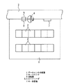
図1〜図8はこの発明の第1及び第2発明の一実施の形態を示す図で、図1はデータセンタの部屋の平面図、図2はカードリーダの斜視図、図3はキー保管箱の斜視図、図4はブロック線図、図5は入室動作フローチャート、図6はキー及び判別カードの取り出し/収納動作フローチャート、図7は退室動作フローチャート、図8は異常検出動作フローチャートであり、図中同一符号は同一部分を示す。
【0013】
図1において、1はデータセンタの部屋、2は部屋1内に設置された小室を形成するサーバラックで、各テナントごとに仕切られており、各サーバラック2にはそれぞれ扉(図示しない)が設けられていて、キーによって施錠可能となっている。3は部屋1の外側に設けられた通路、4は部屋1と通路3の間に設けられた回転扉で、常時回転が阻止されており、正規の人の入室時には上記阻止が解除されて、右回転が許可され、一人だけが通過できるように構成されている。
【0014】
5は部屋1の外側に設置され、回転扉4の近傍に配置された個人判別装置を構成するカードリーダ、6は部屋1の内側に設置され、回転扉4の近傍に配置されたカードリーダ、7は部屋1の内側に設置され、各サーバラック2の扉用のキー及びカードリーダ5,6用の判別カードを一括保管するキー保管箱である。
【0015】
図2において、11はテナントの所持する判別カードを読み取るリーダヘッド、12は判別カードによる判別結果を表示する表示器でOK灯12A及びNG灯12Bを有している。
図3において、13は各テナントごとにサーバラック2の扉を施錠及び解錠するキーを収納するキー収納部で、キー収納部13にはそれぞれ電気的にロックされるふたが設けられている。14は判別カードを読み取るリーダヘッド、15は判別カードによる判別結果を表示する表示器で、OK灯15A及びNG灯15Bを有している。
【0016】
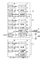
図4において、16はCPU、17はROM、18はRAM、19は伝送装置、20はCPU、21はROM、22はRAM、23は伝送装置、24は回転扉4に接続された回転扉インターフェース、25は入力インターフェースで、ラック2の扉が開いたことを検出する扉センサ26A〜26Nに接続されている。27は出力インターフェース、27aは監視室に設置された警報器(図示しない)へ出力される警報信号、28はCPU、29はROM、30はRAM、31はキー保管箱7のキー収納部13の電気錠を制御するキー収納部制御器、32は伝送装置で、伝送装置19,23,32は相互に接続されている。
【0017】
次に、この実施の形態の動作を図5〜図8を参照して説明する。
(1) 入室動作 (図5)
ステップS1でカードリーダ5のリーダヘッド11は、判別カードをリードするのを待ち、判別カードをリードしたら、ステップS2で判別カードに記載された判別番号がOKか、すなわちあらかじめ登録された本人かを判定し、本人でないと判定すると、ステップS3で表示器12のNG灯12Bを表示するとともに、ステップS1へ戻る。
【0018】
本人であると判定すると、ステップS4で表示器12のOK灯12Aを表示するとともに、ステップS5へ進み、伝送装置19→伝送装置23→回転扉インターフェース24→回転扉4の径路で、回転扉4のロックを解除して右回転を許可する。これでテナントはステップS6で回転扉4を押して部屋1へ入る。このとき、回転扉4はその回転角度を検出する。ステップS7で上記と逆径路、すなわち回転扉4→回転扉インターフェース24→伝送装置23→伝送装置19の径路で、回転扉4の回転角度の信号を入力し、回転扉4が90゜右回転されるのを待つ。
【0019】
回転扉4が90゜右回転したら、ステップS8で再び伝送装置19から信号を送って、回転扉4にその回転を阻止するロックを作動させる。同時に、ステップS9で人が部屋1に入ったことを示す「部屋内フラグ」をRAM18に立てる。
【0020】
(2) キーの取り出し又は収納動作(図6)
ステップS11でキー保管箱7のリーダヘッド14は、判別カードをリードするのを待つ。回転扉4を通って部屋1内に入ったテナントが判別カードをリードさせると、ステップS12で判別番号がOKかを判定し、本人でないと判定すると、ステップS13で表示器15のNG灯15Bを表示するとともに、ステップS11へ戻る。本人であると判定すると、ステップS14で表示器15のOK灯15Aを表示するとともに、ステップS15へ進む。
【0021】
ステップS15でキー収納部制御器31は、該当テナントのキー収納部13のふたのロックを解除する。これで、テナントはステップS16でキー収納部13のふたを開いて、キー収納部13に収納されたキーを取り出し、判別カードを収納してふたを手で閉める。これで、ステップS17でふたにロックが作動して開かなくなる。キーを取り出したテナントは、自分のサーバラック2まで行き、キーで扉を開く。
【0022】
(3) 退室動作(図7)
サーバラック2内のテナントが退室するときは、キーによってラック2の扉を施錠し、入室時と逆方向へ移動してキー保管箱7の前に来て、キー収納部13にキーを収納することになる。このときの動作はキーを取り出すときの逆となり、図6のステップS16でキーを収納し、判別カードを取り出す以外にはキーを取り出すときと同様である。判別カードを取り出したテナントは、入室時と逆方向へ移動して、カードリーダ6の前に来て判別カードを操作することになる。
【0023】
図7のステップS21でカードリーダ6のリーダヘッド11は判別カードをリードするのを待ち、判別カードをリードしたら、ステップS22で本人であるかを確認し、本人でないと判定すると、ステップS23で表示器12のNG灯12Bを表示するとともに、ステップS21へ戻る。本人であると判定すると、S24で表示器12のOK灯12Aを表示するとともに、ステップS25へ進み、入室の場合と同様に、回転扉4のロックを解除して左回転を許可する。これで、テナントはステップS26で回転扉4を押して部屋1を出る。
【0024】
ステップS27で入室時と同様に回転扉4の回転角度の信号を入力し、回転扉4が90°左回転されるのを待つ。回転扉4が90°左回転したら、ステップS28で回転扉4にその回転を阻止するロックを作動させる。同時に、ステップS29で部屋1を出た人の「部屋内フラグ」を解除する。
【0025】
(4) 異常検出動作(図8)
ステップS31でカードリーダ6は、扉センサ26A〜26Nの信号を入力して、サーバラック2の扉が開いているかを監視し、開いていればステップS32へ進み、カードリーダ5からの信号を入力して、該当するテナントの「部屋内フラグ」が一人以上立っているかを判定する。一人以上立っていれば、ステップS33へ進み、キー保管箱7からの入力により、キー保管箱7の該当するキー収納部13にキーが収納されているかを判定する。キーが収納されていなければ、正常時と判定してステップS31へ戻る。
【0026】
次に、ステップS32で一人の「部屋内フラグ」も立っていないと判定されるか、又はステップS33でキーが収納されていると判定されると、ステップS34へ進んで、出力インターフェース27から警報信号27aを出力して、監視室の警報器(図示しない)を鳴動させる。
ここで、ステップS32は不在検出手段を、ステップS31、S32、S34及びステップS31、S33、S34は異常警報手段を構成している。
【0027】
このようにして、ラック2に対応するテナントが部屋1内に不在のとき、ラック2の扉が開くか、又は開いていると、異常とみなして異常警報を出力する。また、キー保管箱7にキーが保管されているとき、ラック2の扉が開くと異常と見なして異常警報を出力するようにしたため、侵入者の発生を検出することができ、警備性を向上することが可能となる。
【0028】
実施の形態2.
この発明の第3発明の一実施の形態を示す。なお、図1〜図4は実施の形態2にも共用する。(以下の実施の形態も同じ。)
この実施の形態は、ラック2に対応するテナントが部屋1内に不在のときに、キー保管箱7にこのテナントのキーが収納されていないとき、又はそのラック2の扉が開いていると、異常と見なして異常警報を出力させるものである。
これにより、侵入者の発生を検出することができ、警備性を向上することが可能となる。
【0029】
実施の形態3.
この発明の第4及び第6発明の一実施の形態を示す。
この実施の形態は、ラック2の扉が開いているときに、テナントがラック2用のキーをキー保管箱7のキー収納部13に収納する操作をしたり、カードリーダ6のリーダヘッド11にカードを操作したりすると、換言すればテナントが部屋1内に不在となるような操作をすると、それらの操作を不感とするか、又は警報を出力するようにしたものである。これらの動作は不在操作検出手段及び注意警告手段(いずれも図示しない)を設けることにより実施できる。
【0030】
これらの操作は、ラック2の扉を閉め忘れて退室しようとしていると判断し、キー保管箱7の場合は、その操作を不感としてキー収納部13のふたのロックを解除せず、キーの収納を不能にするか警報を出力する。また、カードリーダ6の場合は、その操作を不感として回転扉4のロックを解除せず、回転扉4の回転を阻止するか警報を出力する。
これにより、ラック2の扉の閉め忘れを警告することが可能となる。
【0031】
実施の形態4.
この発明の第5及び第6発明の一実施の形態を示す。
この実施の形態は、キー保管箱7のキー収納部13にキーが収納されていないときに、このキーの所持者であるテナントが部屋1内に不在となるような操作(実施の形態3参照)をすると、その操作を不感とするか又は警報を出力するようにしたものである。
これにより、キーをキー収納部13に収納せず、部屋1外に持ち出すことを防止でき、キーの複製及びその悪用を未然に防止することが可能となる。
【0033】
他の実施の形態.
次のように実施することも可能である。
(1) 部屋1の中にラック2を設置するものとしたが、部屋の中の所定のスペースを借りて、テナント側で仕切りを設ける場合もある。この場合は、カードリーダ等で個人判別をして、結果がOKのときだけ仕切り内に入れるようにする。そして、仕切りに設けられた扉が開いているのに、部屋1内の該当テナントが部屋に不在となる操作をしたとき警報を出力する。
【0034】
(2) 部屋1への出入口を開閉する扉は回転扉4に限定されるものではない。鉄道用の出改札ゲートのように1回の入退室を一人に制限するものであればよい。
(3) 上記(2)の他の例として、2枚の扉内に人を閉じ込め、その内部の大きさを1人しか入れないようにするか、又は体重を測定して1人であることを検出するような装置を用いる。
(4) カードリーダは、磁気、光、IC、非接触等の個人判別カードが使用できるものであればよい。また、テンキーやバイオメトリクスを利用した個人判別も可能である。また、それらを併用する。
【0035】
(5) キー保管箱7は部屋1の外に設置する。
(6) ラック2にカードリーダ等の個人判別装置を設置し、判別結果がOKのときラック2の扉を開くようにする。
【0036】
【発明の効果】
以上説明したとおりこの発明では、部屋の中にテナントに対応する複数の小室を設置し、第1発明では、この小室に対応するテナントが部屋内に不在であることが検出され、かつこのテナントに対応する小室の開扉状態が検出されると、また第2発明では、キー保管箱に小室の扉を開閉するキーが収納されているとき、このキーに対応する小室の扉が開くと、また第3発明では、小室に対応するテナントが不在であることが検出されたとき、キー保管箱にテナントに対応するキーが収納されていないか、又はテナントに対応する小室の扉が開いていると、それぞれ異常警報を出力するようにしたので、侵入者の発生が検出され、警備性を向上することができる。
【0037】
また第4発明では、部屋の中にテナントに対応する複数の小室を設置し、この小室の扉が開いているとき、テナントが部屋内に不在となる操作をしたことが検出されると、この不在操作を不感とするか、又は警報を出力するようにしたので、テナントに小室の扉の閉め忘れを警告することができる。
【0038】
また第5発明では、キー保管箱にキーが収納されていないときに、小室に対応するテナントが部屋内に不在となる操作をしたことが検出されると、この不在操作を不感とするか、又は警報を出力するようにしたので、キーを部屋外に持ち出すことを防止し、キーの複製及びその悪用を未然に防止することができる。
【0039】
また第6発明及び第7発明では、テナントが部屋内に不在となる操作を、テナントが入退室者を判断して正規の入退室者の入退室を許可する装置により部屋内から部屋外への通行許可を要求する操作、又はキー保管箱にキーを収納する操作としたので、部屋内に不在となることを事前に検出でき、キーの持ち出しを防止することができる。
【図面の簡単な説明】
【図1】 この発明の実施の形態1を示すデータセンタの部屋の平面図。
【図2】 図1のカードリーダの斜視図。
【図3】 図1のキー保管箱の斜視図。
【図4】 この発明の実施の形態1を示すブロック線図。
【図5】 この発明の実施の形態1を示す入室動作フローチャート。
【図6】 この発明の実施の形態1を示すキー及び判別カードの取り出し/収納動作フローチャート。
【図7】 この発明の実施の形態1を示す退室動作フローチャート。
【図8】 この発明の実施の形態1を示す異常検出動作フローチャート。
【符号の説明】
1 データセンタの部屋、 2 小室(サーバラック)、 4 回転扉、5,6 個人判別装置(カードリーダ)、 7 キー保管箱、 11 リーダヘッド、 13 キー収納部、 14 リーダヘッド、 26A〜26N 小室(サーバラック)の扉センサ。
S31、S32、S34 異常警報手段、 S31、S33、S34 異常警報手段、 S32 不在検出手段。[0001]
BACKGROUND OF THE INVENTION
The present invention relates to an apparatus for guarding a data center in which a plurality of tenant servers are installed in a common room.
[0002]
[Prior art]
In recent years, an increasing number of data centers have Internet provider servers installed as tenants. Therefore, the servers are arranged adjacent to each other.
[0003]
[Problems to be solved by the invention]
In the conventional data center as described above, a large number of servers are arranged in one room, and physical crime prevention equipment is not considered at all. There is. Another problem is that it is not possible to prevent duplication by taking out the key of the rack that houses the server.
[0004]
The present invention has been made to solve the above problems, and it is an object of the present invention to provide a data center security device capable of reducing opportunities for theft of information by an intruder, taking out rack keys, and the like. And
[0005]
[Means for Solving the Problems]
The security device of the data center according to the first aspect of the present invention has a plurality of small rooms corresponding to a tenant installed in a room, and it is detected that the tenant corresponding to the small room is absent in the room, and When an open state of the small room corresponding to the tenant is detected, an abnormality alarm is output.
[0006]
According to a second aspect of the present invention, there is provided a security device for a data center, wherein a plurality of small rooms corresponding to tenants are installed in a room, a key storage box for storing a key for opening and closing the door of the small room is provided, and the key storage box When the door of the small room corresponding to is opened, an abnormal alarm is output.
[0007]
The data center security apparatus according to the third aspect of the present invention is provided with a plurality of small rooms corresponding to tenants in a room, and provided with a key storage box for storing keys for opening and closing the doors of the small rooms. When a tenant is detected to be absent, an error alarm is output if the key corresponding to the tenant is not stored in the key storage box or if the small room door corresponding to the tenant is open. Is.
[0008]
The data center security device according to the fourth aspect of the present invention has a plurality of small rooms corresponding to tenants in a room, and when the door of the small room is open, the tenant corresponding to the small room is absent in the room. When it is detected that an operation is performed, the absence operation is made insensitive or an alarm is output.
[0009]
According to a fifth aspect of the present invention, there is provided a data center security device according to the fourth aspect, wherein a key storage box is provided for storing a key for opening and closing the door of the small chamber, and the key is not stored in the key storage box. The tenant corresponding to the small room is detected to have performed an operation that is absent in the room.
[0010]
According to a sixth aspect of the present invention, there is provided the data center security apparatus according to the above-described apparatus for permitting a regular entry / exit person to enter / exit an operation in which the tenant corresponding to the small room is absent in the room. This is an operation for requesting permission for passage from inside the room to the outside of the above section.
[0011]
According to a seventh aspect of the present invention, there is provided a data center security device, wherein a key storage box is provided in the fourth invention , and a tenant detects that the key has been stored in the key storage box .
[0012]
DETAILED DESCRIPTION OF THE INVENTION
Embodiment 1 FIG.
1 to 8 show one embodiment of the first and second aspects of the invention. FIG. 1 is a plan view of a data center room, FIG. 2 is a perspective view of a card reader, and FIG. 3 is a key storage. 4 is a block diagram, FIG. 5 is a flowchart for entering / storing operation, FIG. 6 is a flowchart for taking out and storing the key and the discrimination card, FIG. 7 is a flowchart for exiting the chamber, and FIG. In the figure, the same reference numerals indicate the same parts.
[0013]
In FIG. 1, 1 is a data center room, 2 is a server rack that forms a small room installed in the room 1, and is partitioned for each tenant, and each
[0014]
5 is a card reader that constitutes a personal identification device installed outside the room 1 and in the vicinity of the revolving door 4; 6 is a card reader that is installed inside the room 1 and arranged in the vicinity of the revolving door 4;
[0015]
In FIG. 2, 11 is a reader head for reading the discrimination card possessed by the tenant, and 12 is a display for displaying the discrimination result by the discrimination card, and has an
In FIG. 3,
[0016]
In FIG. 4, 16 is a CPU, 17 is a ROM, 18 is a RAM, 19 is a transmission device, 20 is a CPU, 21 is a ROM, 22 is a RAM, 23 is a transmission device, and 24 is a revolving door interface connected to the revolving door 4. , 25 is an input interface and is connected to
[0017]
Next, the operation of this embodiment will be described with reference to FIGS.
(1) Entrance operation (Fig. 5)
In step S1, the reader head 11 of the
[0018]
If it is determined that the user is the person himself / herself, the
[0019]
If the revolving door 4 is rotated 90 ° right, a signal is sent again from the
[0020]
(2) Key removal or storage (Fig. 6)
In step S11, the
[0021]
In step S15, the key
[0022]
(3) Exit operation (Fig. 7)
When the tenant in the
[0023]
In step S21 of FIG. 7, the
[0024]
In step S27, a signal of the rotation angle of the rotary door 4 is input in the same manner as when entering the room, and the process waits for the rotary door 4 to be rotated 90 ° counterclockwise. When the revolving door 4 is rotated 90 ° counterclockwise, the lock that prevents the revolving door 4 from rotating is operated in step S28. At the same time, the “in-room flag” of the person who has left the room 1 is canceled in step S29.
[0025]
(4) Abnormality detection operation (Fig. 8)
In step S31, the
[0026]
Next, if it is determined in step S32 that one “in-room flag” is not set, or if it is determined in step S33 that the key is stored, the process proceeds to step S34, and an alarm is output from the
Here, step S32 constitutes absence detection means, and steps S31, S32, S34 and steps S31, S33, S34 constitute abnormality alarm means.
[0027]
In this manner, when the tenant corresponding to the
[0028]
An embodiment of the third invention of the present invention will be shown. 1 to 4 are shared by the second embodiment. (The following embodiments are also the same.)
In this embodiment, when the tenant corresponding to the
Thereby, generation | occurrence | production of an intruder can be detected and it becomes possible to improve security.
[0029]
One embodiment of the fourth and sixth inventions of the present invention is shown.
In this embodiment, when the door of the
[0030]
In these operations, it is determined that the user has forgotten to close the door of the
Thereby, it becomes possible to warn of forgetting to close the door of the
[0031]
Embodiment 4 FIG.
One embodiment of the fifth and sixth inventions of the present invention is shown.
In this embodiment, when a key is not stored in the
As a result, the key can be prevented from being taken out of the room 1 without being stored in the
[0033]
Other embodiments.
It is also possible to carry out as follows.
(1) Although the
[0034]
(2) The door that opens and closes the entrance to the room 1 is not limited to the revolving door 4. What is necessary is just to limit one entry / exit to one person like a railway ticket gate.
(3) As another example of the above (2), a person should be confined in two doors and the size of the inside should be limited to only one person, or the weight should be measured by one person. A device that detects the above is used.
(4) The card reader may be any card reader that can use personal identification cards such as magnetism, light, IC, and non-contact. Individual discrimination using a numeric keypad or biometrics is also possible. Also, use them together.
[0035]
(5) The
(6) Install a personal identification device such as a card reader in the
[0036]
【The invention's effect】
As described above, in the present invention, a plurality of small rooms corresponding to a tenant are installed in the room, and in the first invention, it is detected that the tenant corresponding to the small room is absent in the room, and In the second invention, when a key for opening and closing the small chamber door is stored in the key storage box, when the small chamber door corresponding to the key is opened, In the third invention, when it is detected that the tenant corresponding to the small room is absent, the key storage box does not contain the key corresponding to the tenant, or the door of the small room corresponding to the tenant is open. Since each of them outputs an abnormal alarm, the occurrence of an intruder can be detected and the security can be improved.
[0037]
Further, in the fourth invention, when a plurality of small rooms corresponding to the tenant are installed in the room and the door of the small room is open, if it is detected that the tenant has performed an operation that is absent in the room, Since the absence operation is made insensitive or an alarm is output, it is possible to warn the tenant of forgetting to close the door of the small room.
[0038]
Further, in the fifth invention, when it is detected that the tenant corresponding to the small room has made an operation that is absent in the room when the key is not stored in the key storage box, the absence operation is made insensitive. Alternatively, since an alarm is output, it is possible to prevent the key from being taken outdoors and prevent duplication of the key and its misuse.
[0039]
In the sixth and seventh aspects of the invention , an operation in which the tenant is absent from the room is moved from the inside of the room to the outside of the room by a device that allows the tenant to judge the person entering and leaving the room and permit the entry / exit of the regular person into and out of the room. Since the operation for requesting passage permission or the operation for storing the key in the key storage box is performed, it can be detected in advance that the user is absent from the room, and the key can be prevented from being taken out.
[Brief description of the drawings]
FIG. 1 is a plan view of a data center room according to Embodiment 1 of the present invention.
FIG. 2 is a perspective view of the card reader of FIG.
3 is a perspective view of the key storage box of FIG. 1. FIG.
FIG. 4 is a block diagram showing the first embodiment of the present invention.
FIG. 5 is a flow-in operation flowchart showing the first embodiment of the present invention.
FIG. 6 is a flowchart of a key / discriminating card removal / storage operation according to the first embodiment of the present invention.
FIG. 7 is an exit operation flowchart showing the first embodiment of the present invention.
FIG. 8 is an abnormality detection operation flowchart showing Embodiment 1 of the present invention.
[Explanation of symbols]
DESCRIPTION OF SYMBOLS 1 Data center room, 2 Small room (server rack), 4 Revolving door, 5, 6 Individual discrimination device (card reader), 7 Key storage box, 11 Leader head, 13 Key storage part, 14 Leader head, 26A-26N Small room (Server rack) door sensor.
S31, S32, S34 Abnormal alarm means, S31, S33, S34 Abnormal alarm means, S32 Absence detection means.
Claims (7)
Priority Applications (1)
| Application Number | Priority Date | Filing Date | Title |
|---|---|---|---|
| JP2000320985A JP3916863B2 (en) | 2000-10-20 | 2000-10-20 | Data center security equipment |
Applications Claiming Priority (1)
| Application Number | Priority Date | Filing Date | Title |
|---|---|---|---|
| JP2000320985A JP3916863B2 (en) | 2000-10-20 | 2000-10-20 | Data center security equipment |
Publications (3)
| Publication Number | Publication Date |
|---|---|
| JP2002133538A JP2002133538A (en) | 2002-05-10 |
| JP2002133538A5 JP2002133538A5 (en) | 2005-10-06 |
| JP3916863B2 true JP3916863B2 (en) | 2007-05-23 |
Family
ID=18799186
Family Applications (1)
| Application Number | Title | Priority Date | Filing Date |
|---|---|---|---|
| JP2000320985A Expired - Fee Related JP3916863B2 (en) | 2000-10-20 | 2000-10-20 | Data center security equipment |
Country Status (1)
| Country | Link |
|---|---|
| JP (1) | JP3916863B2 (en) |
Families Citing this family (2)
| Publication number | Priority date | Publication date | Assignee | Title |
|---|---|---|---|---|
| US9355278B2 (en) | 2013-12-27 | 2016-05-31 | Microsoft Technology Licensing, Llc | Server chassis physical security enforcement |
| JP6558942B2 (en) * | 2015-04-30 | 2019-08-14 | 河村電器産業株式会社 | Rack management system |
-
2000
- 2000-10-20 JP JP2000320985A patent/JP3916863B2/en not_active Expired - Fee Related
Also Published As
| Publication number | Publication date |
|---|---|
| JP2002133538A (en) | 2002-05-10 |
Similar Documents
| Publication | Publication Date | Title |
|---|---|---|
| US20070256615A1 (en) | System and method for unattended access to safe deposit boxes | |
| JP2007262695A (en) | Entrance management equipment with enhanced security function, and entrance management method | |
| US7221273B1 (en) | Automated locking system | |
| JP2004169441A (en) | Entrance supervisory device | |
| JP3916863B2 (en) | Data center security equipment | |
| JP2004211538A (en) | Entrance-leaving control system | |
| EP0629764A1 (en) | Security door with biometric identifying device | |
| JP2000145219A (en) | Lock management system | |
| JPH01181888A (en) | Centralized control device for pinball game machine | |
| CN214532499U (en) | Safety room for retention service library | |
| JPH06251219A (en) | Room entry and exiting controller | |
| JP2006144384A (en) | Security enhanced room entry management system | |
| JP2005150925A (en) | Security system | |
| KR102514101B1 (en) | Security system for operating safe deposit boxes | |
| JPH069265Y2 (en) | Access control device | |
| US11810411B1 (en) | System and methods for access control | |
| JPH07229331A (en) | Key managing device and key storing device | |
| KR100334442B1 (en) | apparatus for locking doorway by card | |
| JPH0526917B2 (en) | ||
| JPH11120455A (en) | Room enterance managing system | |
| JP4154013B2 (en) | Management system | |
| JP3578328B2 (en) | Building security equipment | |
| JPH07134785A (en) | Id discrimination device | |
| JP2650517B2 (en) | Key storage device | |
| JPH10162188A (en) | Entry/exiting management device |
Legal Events
| Date | Code | Title | Description |
|---|---|---|---|
| A521 | Written amendment |
Free format text: JAPANESE INTERMEDIATE CODE: A523 Effective date: 20050526 |
|
| A621 | Written request for application examination |
Free format text: JAPANESE INTERMEDIATE CODE: A621 Effective date: 20050526 |
|
| A977 | Report on retrieval |
Free format text: JAPANESE INTERMEDIATE CODE: A971007 Effective date: 20061124 |
|
| A131 | Notification of reasons for refusal |
Free format text: JAPANESE INTERMEDIATE CODE: A131 Effective date: 20061205 |
|
| A521 | Written amendment |
Free format text: JAPANESE INTERMEDIATE CODE: A523 Effective date: 20070115 |
|
| TRDD | Decision of grant or rejection written | ||
| A01 | Written decision to grant a patent or to grant a registration (utility model) |
Free format text: JAPANESE INTERMEDIATE CODE: A01 Effective date: 20070206 |
|
| A61 | First payment of annual fees (during grant procedure) |
Free format text: JAPANESE INTERMEDIATE CODE: A61 Effective date: 20070207 |
|
| R150 | Certificate of patent or registration of utility model |
Free format text: JAPANESE INTERMEDIATE CODE: R150 |
|
| FPAY | Renewal fee payment (event date is renewal date of database) |
Free format text: PAYMENT UNTIL: 20110216 Year of fee payment: 4 |
|
| FPAY | Renewal fee payment (event date is renewal date of database) |
Free format text: PAYMENT UNTIL: 20120216 Year of fee payment: 5 |
|
| FPAY | Renewal fee payment (event date is renewal date of database) |
Free format text: PAYMENT UNTIL: 20130216 Year of fee payment: 6 |
|
| FPAY | Renewal fee payment (event date is renewal date of database) |
Free format text: PAYMENT UNTIL: 20140216 Year of fee payment: 7 |
|
| R250 | Receipt of annual fees |
Free format text: JAPANESE INTERMEDIATE CODE: R250 |
|
| R250 | Receipt of annual fees |
Free format text: JAPANESE INTERMEDIATE CODE: R250 |
|
| LAPS | Cancellation because of no payment of annual fees |