JP3915501B2 - Combustion device and hot water heater - Google Patents
Combustion device and hot water heater Download PDFInfo
- Publication number
- JP3915501B2 JP3915501B2 JP2001377834A JP2001377834A JP3915501B2 JP 3915501 B2 JP3915501 B2 JP 3915501B2 JP 2001377834 A JP2001377834 A JP 2001377834A JP 2001377834 A JP2001377834 A JP 2001377834A JP 3915501 B2 JP3915501 B2 JP 3915501B2
- Authority
- JP
- Japan
- Prior art keywords
- fuel
- combustion
- spray
- hot water
- air
- Prior art date
- Legal status (The legal status is an assumption and is not a legal conclusion. Google has not performed a legal analysis and makes no representation as to the accuracy of the status listed.)
- Expired - Fee Related
Links
Images


Description
【0001】
【発明の属する技術分野】
本発明は、給湯器等に使用される燃焼装置に関するものである。また本発明は、給湯器等の湯水加熱装置に関するものである。
【0002】
【従来の技術】
従来より、給湯装置等に代表される湯水加熱装置には、石油等の液体燃料を噴霧して燃焼させる燃焼装置が多用されている。図12は、燃料を噴霧して燃焼させる燃焼装置を内蔵した給湯装置の断面図である。図12において、100は給湯装置であり、101は燃焼装置である。図12に示す燃焼装置101では、燃焼ケース102を有し、燃焼ケース102の下方に、熱交換器3が設けられている。なお熱交換器3は、当該燃焼ケース102に水管が挿通されたものである。
【0003】
燃焼装置101は、燃料噴射ノズル103とノズル収納筒5と燃焼筒6と送風機7とを有する。燃料噴射ノズル103は、ノズル収納筒5内に収納され、外部から供給された燃料を燃焼筒6内に噴霧するものである。燃料噴射ノズル103の構造については後記する。
【0004】
ノズル収納筒5は、燃焼筒6と接続されて一体化されたものであり、ノズル収納筒5は、燃料噴射ノズル103を直接内蔵するノズル収納内筒9と、その外側に設けられたノズル収納外筒10とによる2重構造となっている。
そしてノズル収納筒5内には、前記した燃料噴射ノズル103の他、点火プラグ8が内蔵されており、当該点火プラグ8によって噴射ノズル103から噴射された燃料に点火される。
ノズル収納内筒9の側面およびノズル収納外筒10の側面には、燃焼筒6の内部に空気を導入するための空気導入口が設けられている。
【0005】
燃焼筒6は図13に示す様に二段形状の筒体であり、ノズル収納筒5に接続された第1燃焼筒11と、当該第1燃焼筒11に連続する第2燃焼筒12とから構成されている。
燃焼筒6の第1燃焼筒11と、ノズル収納筒5の境界部分には、両者を仕切る第1フランジ部15が設けられている。第1フランジ部15は、中央に開口14が設けられている。また第1フランジ部15には、複数の第1気流旋回器17が設けられている。
第1気流旋回器17は、円周状に配列された複数の吹き出し口20を有する。さらに、各吹き出し口20には、空気を燃焼筒6の接線方向に向けて導入するための旋回羽根21が設けられている。
【0006】
第1燃焼筒本体13の周部には、燃焼筒6の内部に空気を導入するための空気導入口16が複数設けられている。
【0007】
第2燃焼筒12は、第1燃焼筒11よりも大径の筒であり、両者の軸心は略一致している。第2燃焼筒12と第1燃焼筒11の接続部分は段状となっており、両者の間には第2フランジ部23がある。
また、第2フランジ部23には、複数の第2気流旋回器18が設けられている。第2気流旋回器18は、円周状に配列された複数の吹き出し口26を有する。さらに、各吹き出し口26には、旋回羽根27が設けられており、この旋回羽根27により空気が燃焼筒6の接線方向に向けて導入される。
第2燃焼筒本体22の周部にも、前記した第1燃焼筒本体13と同様に内部に空気を導入するための空気導入口25が複数設けられている。
【0008】
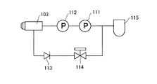
つぎに従来技術で採用されていた燃料噴射ノズル103の構造及びその配管系統について説明する。図14は、従来技術の燃焼装置の燃料系統を示す概念図である。
従来技術で採用されていた燃料噴射ノズル103は、噴霧開口を有し、内部に噴霧開口に至る往き側流路と、噴霧開口から戻る戻り側流路が設けられている。 そして燃料噴射ノズル103の入り側に第1ポンプ111及び第2ポンプ112が直列的に接続されている。ここで第1ポンプ111は吐出量を任意に変更できる電磁ポンプであり、第2ポンプ112は、定差圧ポンプである。
【0009】
また燃料噴射ノズル103の戻り側は、逆止弁113及び電磁弁114を介して第2ポンプ112の吸入側に接続されている。
【0010】
従来技術の燃焼装置101では、燃料タンク115から供給された燃料が第1ポンプ111によって加圧され、第2ポンプ112の吸入側に供給される。燃料は第2ポンプ112によってさらに加圧されて燃料噴射ノズル103に入る。
そして加圧されて高圧状態の燃料は燃料噴射ノズル103突端の噴霧開口に至り、その一部が外部に開放されて霧状に噴射される。
また残余の燃料は第2ポンプの吸い込み側に戻される。
従来技術においては、燃料噴霧量の調節は、第1ポンプ101から吐出される燃料の流量を調節することにより行われていた。
【0011】
また、上記した燃料噴射ノズル103に代わり、特開平5−322153号公報に開示されているような構成を有する燃料噴射ノズル116および配管系統が採用される場合もある。燃料噴射ノズル116は、電磁式の燃料噴射弁を備えている。また、燃料噴射ノズル116には、図15に示すように燃料ポンプ117および燃料フィルタ118が直列的に接続されている。さらに燃料ノズル116には、前記燃料噴射弁の開閉を制御するコントロールユニット120が接続されている。また、燃料の流路には圧力センサ121が設けられている。圧力センサ121は、燃料噴射ノズル116への燃料の供給圧力を調整すべく、コントロールユニット120に接続されている。
【0012】
燃料噴射ノズル116を採用した燃焼装置101では、燃料タンク115から供給された燃料が燃料ポンプ117で加圧され、燃料フィルタ118を経て燃料噴射ノズル116に入る。そして加圧されて高圧状態の燃料は、燃料噴射弁の開度に応じて所定の圧力で霧状に噴射される。
【0013】
次に上記した燃焼装置101における空気の流れについて説明する。
前記した様に燃焼装置101は、送風機7を備え、送風機7により燃料の燃焼に必要な空気がノズル収納筒5及び燃焼筒6内に導入される。
すなわち燃焼装置101においては、空気は、送風機7により空気ケース28内に送り込まれる。そして空気ケース28に導入された空気の一部は、一次空気としてノズル収納筒5に導入される。すなわちノズル収納内筒9の側面に設けられた空気導入口30からノズル収納内筒9内に空気が導入され、燃料噴射ノズル103の近傍で燃料と混合される。一次空気と混合された燃料が、開口14から燃焼筒6内に流れ込む。
【0014】
そして燃焼筒6に二次空気が導入され、燃焼筒6内において火炎が発生する。すなわち燃焼装置101の燃焼筒6には、第1気流旋回器17、第2気流旋回器18及び空気導入口16,25が設けられており、これらから燃焼筒6の内部に二次空気が導入され、燃焼に寄与する。
【0015】
【発明が解決しようとする課題】
ところで給湯器等の家庭用の燃焼機器は、低燃焼量から高燃焼量に渡って安定して燃焼することが必要である。すなわち家庭用の機器で採用される燃焼装置には、高い燃焼量絞り比(T.D.R Turn Down Ratio)が要求される。
【0016】
しかしながら燃料噴射ノズル103を内蔵する燃焼装置101では、上記した様に、第1ポンプの吐出量のみによって燃料噴射ノズル103から噴霧される燃料の量を調節するものであったから、燃焼量絞り比を高くすることが困難であった。
すなわち従来技術の噴霧式燃焼装置では、第1ポンプ111に電磁ポンプを採用し、入力するパルスを変更することにより、燃料噴射ノズル103から吐出される燃料の流量自体を変化させていた。しかしながら電磁ポンプによって変更可能な流量領域は狭く、家庭用給湯器等に要求される燃焼量絞り比(T.D.R)を確保することができないという問題があった。
【0017】
さらに従来技術においては、二次空気の供給についても欠点があり、家庭用給湯器等に要求される燃焼量絞り比に対応することができないという問題があった。
すなわち従来技術で採用する燃料噴射ノズル103は前記したように、燃料噴射ノズル103に供給する燃料の量を増減して燃料の噴射量を加減する。したがって従来技術で採用する燃料噴射ノズル103では、燃焼量が多い時と燃焼量が少ない時とで、噴射開口近傍の燃料の圧力が異なる。そのため燃料噴射ノズル103を使用すると、燃焼量が多い時と、燃焼量が少ない時とで、燃料噴射の初速や噴射パターンが大きく変化する。
【0018】
また、燃料噴射ノズル116を採用した場合においても、燃焼量の多い時と少ない時とで、噴射開口近傍の燃料の圧力が異なる。即ち、燃料噴射ノズル116においては、燃料の噴射量を調整すべく圧力センサ121の検知信号に基づき、燃料噴射ノズル116に供給される燃料の圧力が調整されるが、燃焼量の増減により噴射開口近傍の燃料の圧力が変動してしまう。そのため燃料噴射ノズル116を使用しても、燃焼量が多い時と、燃焼量が少ない時とで、燃料噴射の初速や噴射パターンが大きく変化してしまう。
【0019】
すなわち従来の給湯装置100では、燃焼装置101における燃料の燃焼量が変化すると、燃料噴射ノズル103,116から燃焼筒6内に噴射される燃料の噴霧圧力および噴霧角度が変化する。
ここでこの種の燃焼装置では、効率よく燃焼させるための条件として、燃料に対して二次空気を供給するタイミングが重要である。より端的に説明すれば、燃料の噴霧パターンによって二次空気を供給すべき最適位置が異なる。
【0020】
しかしながら燃焼筒6に二次空気を導入する空気導入口16,25等は、固定的なものとならざるを得ない。そのため従来技術の燃焼装置では、二次空気を導入する空気導入口16,25の位置や大きさは、予想される噴霧パターンの変化に対して最大公約数的な位置となっている。
【0021】
そのため従来技術の燃焼装置101では、燃焼筒6内に拡散している燃料は、空気導入口16,25から供給された空気と混合されるが、空気導入口16,25は、第1燃焼筒11および第2燃焼筒12の所定の位置に設けられているため、燃焼装置101の燃焼量が大きく変動し、燃料の拡散範囲が変動すると、燃料の燃焼に適した位置に空気が到達せず、燃料中の空気量が不足する場合がある。
【0022】
また燃焼筒6内に噴霧される燃料と空気の混合比が適当でないと、燃料の一部が燃焼されずに放出されたり、不完全燃焼を起こしたりする。すなわち、燃料と空気との混合比が不適切な場合は、燃焼装置101のエネルギー効率が低いばかりか、一酸化炭素等の有害ガスを排出してしまう。従って、燃焼装置101は、燃料を安定燃焼可能な燃焼量の範囲が大幅に制限されてしまうという問題を有する。
【0023】
また、上記した給湯装置100に代表される湯水加熱装置は、装置全体をなるべくコンパクトな構成とすることが望まれており、これに伴い燃焼装置101の占有体積も小さくならざるを得ない。燃焼装置101は、燃焼量の増減に伴い燃焼状態が変化するため、熱交換器3における熱交換効率に変動が生じ、湯水の加熱制御が複雑とならざるを得ないという問題がある。また、燃焼装置101は、燃焼状態が不均一であるため、熱交換器3に不均一な熱応力が作用し、熱交換器3の寿命が短くなってしまうという問題もある。
【0024】
そこで本発明は、上記した問題点に鑑み、広範囲な燃焼量において安定して燃焼駆動できる燃焼装置および湯水加熱装置を提供することを目的とした。
【0025】
【課題を解決するための手段】
上記した課題を解決すべく提供される請求項1に記載の発明は、液体燃料を噴霧する噴霧手段と、該噴霧手段により噴霧された燃料を燃焼させる燃焼筒を有し、当該燃焼筒に空気導入口が設けられた燃焼装置において、前記噴霧手段は噴射開口近傍の燃料の圧力が一定の状態下において単位時間当たりの燃料噴射量を変更することが可能であり、噴霧手段から燃料が空気導入口又はその近傍に集中的に至る様に噴霧されるものであり、前記噴霧手段は、噴霧ノズルと、該噴霧ノズルに所定の圧力を印加する加圧手段と、前記噴霧ノズルからの燃料噴霧を断続させる燃料噴霧アクチュエータと、該燃料噴霧アクチュエータによる燃料噴霧の断続タイミングを制御することで前記噴霧ノズルから噴霧される燃料の噴霧量を制御する噴霧制御手段とを備え、前記噴霧ノズルの先端近傍には、あらかじめ定められた特定の方向に燃料を噴射する燃料噴射方向規制手段を設け、さらに、前記燃料噴射方向規制手段と前記燃料噴霧アクチュエータとの間に燃料を貯留する空間を設けたことを特徴とする燃焼装置である。
【0026】
ここで「噴霧手段から燃料が空気導入口又はその近傍に集中的に至る様に噴霧される」とは、噴霧手段から空気導入口又はその近傍に向かって直接的に燃料が噴霧される場合の他、燃料が送風に巻き込まれて流れ、空気導入口又はその近傍に集中的に至る場合を含む趣旨である(請求項2においても同じ)。
【0027】
請求項1に記載の構成によれば、燃料噴射量が変化しても燃焼筒内における燃料の拡散状態をほぼ均一とすることができる。よって、上記した燃焼装置において、燃焼筒内に噴射される燃料は、噴射量の大小にかかわらずほぼ均等に空気と混合される。従って、本発明の燃焼装置は、燃焼量にかかわらず燃焼駆動を安定して行える。
【0028】
また、上記したような構成とすれば、燃焼筒内における燃料の拡散状態がほぼ均一であるため、燃料を燃焼させる際に空気を導入すべき位置のみに空気導入口を設ければよい。すなわち、かかる構成によれば、空気を導入すべき位置から集中的に空気を導入することができるため、燃料と空気とが確実に混合され、燃料の燃焼状態を一層安定化できる。
【0029】
また、本発明の燃焼装置において燃焼筒内に噴霧される燃料は、直接或いは燃焼筒内の気流に乗るなどして空気導入口又はその近傍に集中的に至り、前記空気導入口から流入した空気と迅速かつ十分に混合される。よって、単位時間当たりの燃料噴射量がいかなる量であっても、燃料と空気との混合状態がほぼ均等であり、燃焼状態が安定している。また、燃焼状態が安定しているため、燃料の噴霧量が変化しても一酸化炭素等の有害ガスやススがほとんど発生しない。
【0030】
請求項2に記載の発明は、液体燃料を噴霧する噴霧手段と、該噴霧手段により噴霧された燃料を燃焼させる燃焼筒を有し、当該燃焼筒に空気導入口が設けられた燃焼装置において、前記噴霧手段は一定の燃料噴霧速度及び一定の噴霧パターンを維持した状態下において単位時間当たりの燃料噴射量を変更することが可能であり、噴霧手段から燃料が空気導入口又はその近傍に集中的に至る様に噴霧されるものであり、前記噴霧手段は、噴霧ノズルと、該噴霧ノズルに所定の圧力を印加する加圧手段と、前記噴霧ノズルからの燃料噴霧を断続させる燃料噴霧アクチュエータと、該燃料噴霧アクチュエータによる燃料噴霧の断続タイミングを制御することで前記噴霧ノズルから噴霧される燃料の噴霧量を制御する噴霧制御手段とを備え、前記噴霧ノズルの先端近傍には、あらかじめ定められた特定の方向に燃料を噴射する燃料噴射方向規制手段を設け、さらに、前記燃料噴射方向規制手段と前記燃料噴霧アクチュエータとの間に燃料を貯留する空間を設けたことを特徴とする燃焼装置である。
【0031】
かかる構成によれば、燃焼筒内における燃料の拡散範囲及び密度をほぼ一定とすることができる。すなわち、燃料の噴射量が変化しても、燃焼筒内における燃料と空気との混合状態を一定とすることができる。また、上記したような構成とすれば、燃焼筒内における燃料の拡散状態がほぼ均一であるため、燃料を燃焼させる際に空気を導入すべき位置のみに空気導入口を設け、空気を集中的に導入することでより一層火炎の安定化が図られる。よって、本発明の燃焼装置において、燃焼筒内に発生する火炎の状態は、燃焼量にかかわらず安定している。
【0032】
また、本発明の燃焼装置において燃焼筒内に噴霧される燃料は、直接或いは燃焼筒内の気流に乗るなどして空気導入口又はその近傍に集中的に至り、空気と十分混合される。よって、上記燃焼装置は、燃焼量が変化し、燃焼筒内に噴射される単位時間当たりの燃料の量が変動しても、燃料と空気との混合状態が良好であり、燃焼駆動を安定して行える。
【0033】
また上記したように、本発明の燃焼装置は、燃焼状態が安定しているため、燃料の不完全燃焼に伴う一酸化炭素などの有害ガスやススがほとんど発生しない。よって、前記燃焼装置は、環境に調和した燃焼駆動が可能であり、ススの堆積などによる装置の故障もほとんど起こらない。
【0034】
請求項1,2に記載の燃焼装置によれば、燃料の燃焼量が変動しても、燃焼領域内に燃料をほぼ一定の拡散状態となるように噴霧することができる。また、燃焼領域内に噴霧される燃料は、燃料噴射方向規制手段により方向が制限されて噴霧されるため、燃焼量にかかわらず常に一定の方向に噴霧される。一方、燃焼領域内に導入される空気は、常に燃焼領域内の所定の位置に導入される。よって、前記燃焼領域内において、燃料と空気とは、燃焼量にかかわらず常に一定の混合状態となり燃焼される。従って、本発明の燃焼装置は、燃焼量の増減に左右されることなく常に燃焼状態が安定しており、湯水を高効率かつ精度よく加熱することができる。
【0035】
また、請求項1,2に記載の燃焼装置において、燃料噴射ノズルは、燃料噴射方向規制手段と燃料噴霧アクチュエータとの間に燃料を貯留する空間を有し、燃料を噴霧しなければならないときには、常に燃料噴射ノズルの先端近傍に燃料が貯留されている。そのため、燃焼量の増減に伴って燃料の噴霧量が変化しても、噴霧すべき量の燃料を噴霧すべきタイミングで的確に噴霧でき、安定した燃焼駆動が可能である。
【0036】
請求項3に記載の発明は、噴霧手段から燃料が空気導入口又はその近傍を目標として噴霧されることを特徴とする請求項1又は2に記載の燃焼装置である。
【0037】
かかる構成によれば、噴霧手段から噴霧される燃料は、確実に空気導入口あるいはその近傍に集まる。従って、燃料は、空気と迅速かつ十分に混合されて完全燃焼できる。また、燃料が完全燃焼でき、噴霧された燃料の量に応じた燃焼量が得られるため、エネルギー効率が高い。さらに、燃料の不完全燃焼による一酸化炭素などの有害ガスやススの発生を抑制できる。
【0038】
請求項4に記載の発明は、噴霧手段は、燃料に圧力を印加する加圧手段と、噴霧制御手段を有し、当該噴霧制御手段が、燃料の噴霧を断続的にあるいは周期的な強弱をもって行わしめるものであり、噴霧の断続あるいは強弱のタイミングを制御することによって単位時間当たりの燃料噴射量を変更することができることを特徴とする請求項1乃至3のいずれかに記載の燃焼装置である。
【0039】
かかる構成によれば、単位時間当たりの燃料噴射量を容易かつ的確に調整しつつ、燃焼筒内における燃料の拡散状態を均一とすることができる。よって、本発明の燃焼装置によれば、燃料と空気とが確実に混合され、燃焼駆動により燃焼筒内に発生する火炎を燃焼量にかかわらず安定化できる。
【0040】
また、本発明の燃焼装置は、燃焼筒内における燃料の拡散状態がほぼ均一であるため、燃料を燃焼させる際に空気を導入すべき位置のみに空気導入口を設け、集中的に空気を導入する構成とすることができる。かかる構成によれば、燃料と空気とが確実に混合され、燃料の燃焼状態をより一層安定化できる。
【0041】
本発明の燃焼装置は、燃焼状態が安定しているため、燃料の不完全燃焼に伴う一酸化炭素などの有害ガスやススがほとんど発生しない。よって、前記燃焼装置は、環境に調和した燃焼駆動が可能であり、ススの堆積などによる装置の故障もほとんど起こらない。
【0042】
本発明の燃焼装置は、液体燃料を噴霧する噴霧手段を有し、噴霧手段から噴霧された燃料を燃焼させる燃焼装置において、前記噴霧手段は、燃料に圧力を印加する加圧手段と、燃料の噴霧を断続的にあるいは周期的な強弱をもって行わしめる噴霧制御手段を有し、噴霧の断続あるいは強弱のタイミングを制御することによって単位時間当たりの燃焼量を変更することができることを特徴とするものであってもよい。
【0043】
上記した燃焼装置において、燃料は、噴霧制御手段により断続的にあるいは周期的な強弱をもって噴霧されるため、燃料を均一に拡散しつつ単位時間当たりの燃焼量を調整することができる。すなわち、上記した構成の燃焼装置は、燃焼量が変化しても、燃焼駆動により形成される火炎の状態は変化しない。そのため、前記燃焼装置は、燃焼量にかかわらず燃料と空気との混合状態がほぼ一定であり、いかなる燃焼量であっても安定して燃焼駆動することができる。
【0044】
また、上記燃焼装置は、燃焼状態が安定しているため、燃料の噴霧量が変化しても一酸化炭素等の有害ガスがほとんど発生しない。さらに、ススの発生量も少ないため、本発明の燃焼装置は、ススの堆積による故障や燃焼不良がほとんど起こらない。
【0045】
請求項5に記載の発明は、送風機を有し、さらに燃焼筒は、その周囲に複数の空気導入口を有し、前記送風機によって発生した送風が空気導入口から燃焼筒内に導入されることを特徴とする請求項1乃至4のいずれかに記載の燃焼装置である。
【0046】
かかる構成によれば、燃焼筒内に噴霧された燃料の燃焼に必要な空気を確実に供給でき、燃焼駆動を安定して行える。よって、本発明の燃焼装置によれば、燃焼筒内に噴霧された燃料が確実に燃焼し、供給された燃料の量に見合った発熱量を得ることができる。また、燃料の大部分が完全燃焼するため、燃料が燃焼して発生する燃焼ガス中には一酸化炭素などの有害ガスやススはほとんど含まれず、これらによる環境破壊や装置の故障が発生しない。
【0047】
また、本発明の燃焼装置は、燃焼筒内における燃料の拡散状態がほぼ均一であるため、燃料を燃焼させる際に空気を導入すべき位置のみに空気導入口を設け、集中的に空気を導入する構成とすることができる。かかる構成によれば、燃料と空気とが確実に混合され、燃料の燃焼状態をより一層安定化できる。
【0048】
請求項6に記載の発明は、燃料は一定のパターン及び/又は一定の気流に沿って流れ、燃焼筒の内周近傍に至り、当該燃料が流れ至たる部位に空気導入口が設けられていることを特徴とする請求項1乃至5のいずれかに記載の燃焼装置である。
【0049】
かかる構成によれば、燃料は、燃焼筒の内周近傍において空気と十分かつ確実に混合され完全燃焼される。また、燃料が完全燃焼されるため、エネルギー効率が高く、噴霧された燃料の量に相応する発熱量が得られる。さらに、燃料の不完全燃焼による一酸化炭素などの有害ガスの発生がほとんどない。
【0050】
請求項7に記載の発明は、燃料の噴霧はデューティ比制御によって断続され、単位時間当たりの燃料噴射量が変更されるものであることを特徴とする請求項1乃至6のいずれかに記載の燃焼装置である。
【0051】
かかる構成によれば、単位時間当たりの燃料噴射量が、前記単位時間中に占める噴射時間の割合で決定されるため、噴霧手段から噴霧される燃料の噴霧状態が均一である。よって、燃焼量が変化し燃料噴射量が変更されても、燃料の拡散状態が一定であるため、空気と燃料との混合状態もほぼ一定である。そのため、上記燃焼装置は、燃焼量にかかわらずほぼ一定の燃焼状態を維持でき、安定して燃焼駆動できる燃焼量範囲が広い。
【0052】
請求項8に記載の発明は、燃焼部と、水を加熱する熱交換部と、送風機を有し、燃焼部で発生した燃焼ガスを熱交換部に送り、熱交換部で水を加熱する湯水加熱装置において、燃焼部には請求項1乃至7のいずれかに記載の燃焼装置が装着され、送風機の送風が燃焼装置に導入されることを特徴とする湯水加熱装置である。
【0053】
上記した燃焼装置は、要求される燃焼量の大小にかかわらず、安定した燃焼駆動が可能であり、要求される燃焼量に相応した熱エネルギーを放出することができる。すなわち、上記した湯水加熱装置は、燃焼量が変化しても、要求に応じて的確に熱エネルギーを熱交換部に付与することができる。よって、本発明の湯水加熱装置は、燃焼部における燃焼可能範囲が広く、湯水を幅広い温度範囲で精度よく加熱できる。
【0054】
また、請求項8に記載の湯水加熱装置は、燃焼ケースを有し、当該燃焼ケースに燃焼装置が取り付けられ、さらに燃焼ケースに水管が挿通されて熱交換部が構成されていることを特徴とするものであってもよい(請求項9)。
【0055】
さらに、請求項8に記載の湯水加熱装置は、水が溜められる貯湯部と、貯湯部を貫通する燃焼ガス通路部を有し、燃焼部で発生した燃焼ガスを燃焼ガス通路部に導入して貯湯部内の水を加熱することを特徴とするものとすることも可能である(請求項10)。
【0056】
上記した本発明の湯水加熱装置は、燃料を燃焼する燃焼領域と、該燃焼領域に燃料を噴霧する噴霧手段を有し、水若しくは湯を加熱する湯水加熱装置において、前記噴霧手段は、噴霧ノズルと、該噴霧ノズルに所定の圧力を印加する加圧手段と、前記噴霧ノズルからの燃料噴霧を断続させる燃料噴霧アクチュエータと、該燃料噴霧アクチュエータによる燃料噴霧の断続タイミングを制御することで前記噴霧ノズルから噴霧される燃料の噴霧量を制御する噴霧制御手段とを備え、前記燃焼領域には、燃料の燃焼に要する燃焼用空気を特定の位置から供給する空気導入口を配置すると共に、前記噴霧ノズルの先端近傍には、あらかじめ定められた特定の方向に燃料を噴射する燃料噴射方向規制手段を設けたことを特徴とするものであってもよい。
【0057】
かかる構成によれば、燃焼に要する燃料がいかなる量であっても、燃焼領域内に燃料をほぼ一定の拡散状態となるように噴霧することがでる。また、燃焼領域内に噴霧される燃料は、燃料噴射方向規制手段により噴射の方向が制限されるため、燃焼量にかかわらず常に一定の方向に噴霧される。一方、空気は、空気導入口が燃焼領域の特定の位置に設けられているため、常に燃焼領域内の所定の位置に導入される。よって、前記燃焼領域内に導入された燃料と空気とは、燃焼量にかかわらず常に一定の混合状態となり燃焼される。従って、上記した構成の湯水加熱装置は、燃焼量にかかわらず燃料の燃焼状態が常にほぼ一定であり、湯水を高効率かつ精度よく加熱することができる。
【0058】
上記した本発明の湯水加熱装置は、燃料を燃焼する燃焼領域と、該燃焼領域に燃料を噴霧する噴霧手段を有し、水若しくは湯を加熱する湯水加熱装置において、前記噴霧手段は、噴霧ノズルと、該噴霧ノズルに所定の圧力を印加する加圧手段と、前記噴霧ノズルからの燃料噴霧を断続させる燃料噴霧アクチュエータと、該燃料噴霧アクチュエータによる燃料噴霧の断続タイミングを制御することで前記噴霧ノズルから噴霧される燃料の噴霧量を制御する噴霧制御手段とを備え、前記燃焼領域には、燃料の燃焼に要する燃焼用空気を特定の位置から供給する空気導入口を配置すると共に、前記噴霧ノズルの先端近傍には、あらかじめ定められた特定の方向に燃料を噴射する燃料噴射方向規制手段を設け、さらに、前記燃料噴射方向規制手段と前記燃料噴霧アクチュエータとの間に燃料を貯留する空間を設けたことを特徴とするものであってもよい。
【0059】
かかる構成によれば、燃料の燃焼量が変動しても、燃焼領域内に燃料をほぼ一定の拡散状態となるように噴霧することがでる。また、燃焼領域内に噴霧される燃料は、燃料噴射方向規制手段により方向が制限されて噴霧されるため、燃焼量にかかわらず常に一定の方向に噴霧される。一方、燃焼領域内に導入される空気は、常に燃焼領域内の所定の位置に導入される。よって、前記燃焼領域内において、燃料と空気とは、燃焼量にかかわらず常に一定の混合状態となり燃焼される。従って、本発明の湯水加熱装置は、燃焼量の増減に左右されることなく常に燃焼状態が安定しており、湯水を高効率かつ精度よく加熱することができる。
【0060】
また、上記した構成のの湯水加熱装置において、燃料噴射ノズルは、燃料噴射方向規制手段と燃料噴霧アクチュエータとの間に燃料を貯留する空間を有し、燃料を噴霧しなければならないときには、常に燃料噴射ノズルの先端近傍に燃料が貯留されている。そのため、燃焼量の増減に伴って燃料の噴霧量が変化しても、噴霧すべき量の燃料を噴霧すべきタイミングで的確に噴霧でき、安定した燃焼駆動が可能である。
【0061】
【発明の実施の形態】
以下、本発明の一実施形態である給湯装置(湯水加熱装置装置)および燃焼装置について説明する。なお、本実施形態の給湯装置および燃焼装置は、上記した従来の燃焼装置101とほぼ同様の構成を有するため、共通する部分については同一の符号を付し、詳細の説明については省略する。図1は、本実施形態の給湯装置の要部の一部を破断した正面図である。また、図2は、図1の給湯装置に採用されている燃焼装置を示す図である。図3は、本実施形態の燃焼装置が具備している燃料噴射ノズルの断面図である。
【0062】
図1において、1は本実施形態の給湯装置(湯水加熱装置)である。また、図2において、2は本実施形態の給湯装置1に用いられる燃焼装置である。4は本実施形態の燃焼装置2に採用される燃料噴射ノズルである。本実施形態の燃焼装置は、従来の燃焼装置101と同様に、端部が開放したノズル収納筒5と、ノズル収納筒5の端部に接続された燃焼筒6と、燃焼筒6内に空気を送り込む送風機7とを備えている。
【0063】
本実施形態の燃焼装置2は、ノズル収納筒5に内蔵されている燃料噴射ノズルの構造が大きく異なる。本実施形態において、ノズル収納筒5に内蔵されている燃料噴射ノズル4は、図3に示すような構造を有し、極めて短い時間で断続的に開閉する機能を備える。すなわち燃料噴射ノズル4は、本体ケース41内にアクチュエータ42と、アクチュエータ42を駆動させるための電磁コイル43と、アクチュエータ42に連動する弁44とを有する。本体ケース41の端部には、内部に燃料を供給するための燃料供給部45が設けられている。
【0064】
本体ケース41の内部には、燃料供給部45から供給された燃料が流通する燃料流路47が設けられている。
本体ケース41の先端には、ノズルチップ50が取り付けられている。ノズルチップ50には、燃料の流出口51が複数放射状に設けられており、これらは燃料噴射方向規制手段として機能する。
【0065】
また本体ケース41には、接続端子48が設けられている。接続端子48は、電磁コイル43に接続されており、接続端子48に電流を供給すると電磁コイル43が励磁される。その結果、本体ケース41内のアクチュエータ42が駆動し、アクチュエータ42と連動する弁44が開く。すなわち本実施形態で採用する燃料噴射ノズル4は、接続端子48に電流が供給されている間、弁44が開き、電流が停止すると弁44が閉じる。弁44は、極めて鋭敏に反応し、瞬間的に開閉される。
【0066】
また接続端子48には、図4に示すように弁44の開閉を制御するための噴霧制御手段49が接続されている。噴霧制御手段49は、電磁コイル43にパルス電流を供給するものである。上記した様に、本実施形態で採用される燃料噴射ノズル4は、接続端子48に電流が供給されている間、弁44が開き、電流が停止すると弁44が閉じるので、供給されるパルスがONである時に瞬間的に弁44が開き、OFFになると瞬間的に弁44が閉じる。
【0067】
また本実施形態では、燃料噴射ノズル4は、要求される燃焼量に応じてデューティー比制御される。すなわち必要な燃焼量に応じてパルスのON時間が変化し、弁44が開いている時間が変わる。より具体的には、要求される燃焼量が多い場合は、パルス周期あたりのON時間が長く、長い時間、弁44が開いている。逆に要求される燃焼量が少ない場合は、パルス周期あたりのOFF時間が長く、弁44が閉止している時間が相対的に長い。本実施形態で採用する燃料噴射ノズル4は、こうして燃料噴射を断続し、断続のタイミングを制御することにより総燃焼量を変化させる。
【0068】
また本実施形態では、燃料噴射ノズル4の燃料供給部45に加圧手段たるポンプ52が直列的に接続されている。ここでポンプ52は、流量に係わらず常時一定の吐出圧を保持する機能を備えている。
【0069】
したがって、本実施形態では、燃料の噴射量に係わらず、弁44には常時一定の圧力が掛かっている。
そして前記した様に、接続端子48にパルス電流が流れると、弁44が開いてノズルチップ50側に燃料が流れ、ノズルチップ50から燃料が噴射される。
ここで前記した様に、本実施形態では、燃料の噴射量に係わらず、弁44には常時一定きの圧力が掛かっているから、接続端子48にパルス電流が流れて弁44が開き、ノズルチップ50側に燃料が流れた時におけるノズルチップ50周辺の燃料の圧力は一定である。
そのため接続端子48に供給されるパルス電流がONになった時は、ノズルチップ50から常に一定量(単位時間あたり)の燃料が、一定の速度で、一定の角度に向かって噴射される。
従ってパルス電流がONになった時に燃料噴射ノズル4から燃料が噴射されるが、燃料噴射ノズル4から噴射される燃料の噴霧パターンは、常に一定である。 また本実施形態では、燃料噴射ノズル4は、要求される燃焼量に応じてデューティー比制御されるので、燃料噴射ノズル4は噴射開口近傍の燃料の圧力が一定の状態下において単位時間当たりの燃料噴射量を変更することが可能である。
【0070】
この様に、本実施形態では、圧力調整されノズルチップ50に至った燃料は、燃料の噴射量にかかわらず所定の噴霧圧力で流出口51から燃焼筒6内に放射状に噴霧され、燃焼筒6内で一定の噴霧パターンを描く。
したがって本実施形態では、一定の燃料噴霧速度及び一定の噴霧パターンを維持した状態下において単位時間当たりの燃料噴射量を変更することが可能である。
そして本実施形態では、燃料噴射ノズル4から噴射される燃料の圧力は、燃焼筒6に設けられた空気導入口16,25あるいはその近傍に集中的に到達するように調整されている。
図6に示す実施形態では、燃料噴射ノズル4から噴射される燃料の圧力、及び噴射角度は、燃焼筒6の第2燃焼筒本体22の周部に設けられた空気導入口25に直接的に到達する様に調整されている。
【0071】
よって、燃料噴射ノズル4から噴射された燃料の大部分は、空気導入口25から流入した空気と十分攪拌・混合される。その結果、燃料噴射ノズル4から噴射された燃料は、大部分が容易に完全燃焼できる。
【0072】
また、本実施形態の燃焼装置2において、燃焼筒6は、従来の燃焼装置101と同様に第1燃焼筒11と第2燃焼筒12とが接続されたものであるが、一部の構造が従来のものと異なる。
以下、従来技術と異なる点に重点をおいて説明する。
本実施形態において、第1燃焼筒本体13および第2燃焼筒本体22に設けられている空気導入口16,25は、燃料噴射ノズル4から噴射される燃料が一定のパターン及び/又は一定の気流に乗った際に、燃料が流れ至る部位にのみに設けられている。そのため、空気導入口16,25の数は、従来の燃焼装置101の場合に比べて少ない。従って、空気導入口16,25から燃焼筒6内に流入する空気は、燃料噴射ノズル4から噴射された燃料が到達する位置に集中的に流れ込み、燃料と空気との攪拌を一層促進させる。
【0073】
また、燃焼装置2の燃焼筒6は、第2燃焼筒12の構造が従来のものと異なる。図6は、燃焼筒6を開口側から観察した斜視図である。図7は、本実施形態における第2燃焼筒12近傍の拡大斜視図である。第2燃焼筒12に設けられた第2気流旋回器18の吹き出し口26の後方には、環状の旋回空気調整板65が設けられている。旋回空気調整板65は、その前面(下面)が第2燃焼筒12の第2フランジ部23の後面(上面)と密着するように取り付けられている。旋回空気調整板65には、第2気流旋回器18の吹き出し口26の位置にあわせて旋回空気調整板空気孔66が形成されており、送風機7からの空気が旋回空気調整板空気孔66を経由して吹き出し口26に供給される。吹き出し口26から第2燃焼筒12内に吹き込む気流は、ほぼ第2フランジ部23の前面に沿う。旋回空気調整板空気孔66の大きさは、吹き出し口26より十分小さいため、第2気流旋回器18から流入する空気の量は、ほぼ旋回空気調整板空気孔66の大きさにより調整される。
【0074】
図6,7に示すように、第2気流旋回器18の複数の吹出し口26の下流(図6,7では上方)に、中心部に円孔を有する円板形状の邪魔板67が第1燃焼筒11及び第2燃焼筒12と同軸に設けられている。邪魔板67は、第2燃焼筒本体22の内周面68にスポット溶接されている。そして邪魔板67、第2フランジ部23及び第2燃焼筒本体22の内壁によって、三方が囲まれ、第2フランジ部23にそった環状の流路69が形成される。
【0075】
吹出し口26の各々から第2燃焼筒12内に流入する空気は、吹出し口26からほぼ接線方向に吹き出された後、第2燃焼筒本体22の周壁面に衝突して方向を転じるが、燃焼装置2における下流方向には邪魔板67が存在するため、環状の流路69に沿って旋回しながら中心方向へ向きを変えて流れることになる。そのため、燃料および未燃焼ガスは中心方向に押し込まれながら混合する。その結果、燃料噴射ノズル4から噴射された燃料の一部で、空気導入口16,25あるいはその近傍に到達できなかった燃料も空気と十分混合され、完全燃焼する。
【0076】
また本実施形態では、燃焼筒6の下方に、図5に示すような燃料拡散部材55が取り付けられている。燃料拡散部材55は、中心に円板部56を有し、脚部57によって円板部56を支持する構成となっている。脚部57は、断面形状が略「コ」字形をしている。脚部57は、円板部56に対してやや傾斜して取り付けられている。
【0077】
燃料拡散部材55の両端部分には、取り付け部58が形成されている。取り付け部58は水平部59を有する。水平部59の略中央部には、ネジ挿通孔60が設けられている。水平部59の先端側は折り返され、折り返し部61が形成されている。すなわち、本実施形態において、取り付け部58は、鉤状の形状であり、係合部として機能する。燃料拡散部材55は、取り付け部58を燃焼筒6の下方に係合させ、ネジ挿通孔60を介してネジ止めすることで固定されている。燃料噴射ノズル4から噴射される燃料は、燃料拡散部材55により攪拌が一層促進され、燃焼筒6内に噴霧される。
【0078】
本実施形態の燃焼装置2は、燃料が燃焼量にかかわらず一定の圧力で燃焼筒6内に噴霧されるため、燃焼筒6内における燃料の噴霧状態が常にほぼ一定である。そのため、燃焼装置2は、いかなる燃焼条件の下でも、空気と燃料との混合状態が良好であるため燃料は完全燃焼でき、一酸化炭素の発生量や未燃ガスの排出量を最小限に抑制できる。また、本実施形態の燃焼装置2では、燃焼筒6内における空気とガスの攪拌作用が大きいため、局所的な高温領域が形成されにくく、窒素酸化物の発生量も最小限に抑制できる。さらに、燃焼装置2において、燃料の大部分が完全燃焼されるため、ススの発生量が少なく、第1燃焼筒11と第2燃焼筒12との境界部に形成される段部や第2燃焼筒本体22などのススが付着し易い部分にもほとんどススが付着しない。
【0079】
以上説明した実施形態では、図6に示す様に、燃料噴射ノズル4から噴射される燃料の圧力、及び噴射角度は、燃焼筒6の第2燃焼筒本体22の周部に設けられた空気導入口25に直接的に到達する様に調整された構成を例示した。
しかし燃焼筒6内に生じる旋回流によっては、図8に示すように空気導入口25に届かない範囲に噴射されることが望ましい場合もある。すなわち図8に示す実施形態では、燃料噴射ノズル4から噴射される燃料の噴射角度は、空気導入口25に向かうものの、その圧力は、先の実施形態よりも低く、燃料は、空気導入口25の近傍に噴射されることとなる。
【0080】
なお、図8に示す実施形態では、第一フランジ部15に板状の流路形成部材70が嵌合され、流路形成部材70と第一フランジ部15との間に4ケの管状空気流路71が形成されている。
すなわち、板状の流路形成部材70は、プレス、溶接等により製造されるものであり、外形形状が円板状であって、その外径は、第一フランジ部15のそれと等しい。また流路形成部材70の中心には、開口72が設けられている。開口72の直径は、前記した第一フランジ部15の開口14に等しい。そして流路形成部材70には、一面に4ケの管状空気流路71が設けられている。管状空気流路71は、いずれも外周から中心の開口近傍に至る長さである。管状空気流路71の先端は開放されている。
管状空気流路71は、第一フランジ部15の表面と前記した流路形成部材70の合致面の空隙によって形成される。
【0081】
各管状空気流路71は、その基部に空気導入口74を、また、その先端に空気ノズル73を有する。これらは、先の実施形態における第一フランジ部15に設けられていた第一気流旋回器17に代わるものである。空気ノズル73から吹き出す空気は底面視で時計回りに旋回して保炎効果を加える。
【0082】
またさらに図9に示すようにように複数の空気導入口25の間に燃料を噴射してもよい。
なお図9に示す実施形態は、円板形状の邪魔板67を持たない。
【0083】
また図10に示す例は、円板形状の邪魔板67を持たず、且つ管状空気流路71を備えた例である。図10に示す実施形態では、管状空気流路71は、流路に中途にも空気吹き出し口を持つ。
【0084】
また、上記した実施形態は、いずれも段状の燃焼筒を採用したが、本発明では段形状に限定されるものではない。すなわち、本発明の燃焼装置では、燃料の量にかかわらず燃料の噴霧パターンが一定であるから、燃焼筒を段状にする必要性に乏しい。そのため、単一直径の燃焼筒やテーパ状の燃焼筒を採用することも可能である。
【0085】
また、上記した実施形態では、燃料噴射ノズルはパルスに応じて断続的に燃料噴射するものを採用した。すなわち、上記した実施形態では、パルスがOFFの時は燃料噴射を停止する。しかしながら、上述の説明は弁44のリークを許さないものではなく、実際上は僅かに燃料が噴射される場合が多い。また、積極的にパルスがOFFの場合にも僅かに燃料を噴射せてもよい。すなわち、パルスがOFFの時に燃料噴射を完全に停止させると、燃焼装置が失火する場合がある。そのため、パルスがOFFの時に燃料を僅かに噴射させ失火を防ぐ。この場合は、燃料の噴射は周期的な強弱をもって行われることとなる。
【0086】
続いて本発明の第2実施形態の給湯装置について説明する。なお、本実施形態において、上記第1実施形態の給湯装置と同一の部分については、同一の符号を付し、詳細の説明については省略する。
【0087】
図11は、本実施形態の給湯装置を示す模式図である。図11において、80は本実施形態の給湯装置である。給湯装置80は、いわゆる貯湯式給湯装置である。給湯装置80は、大別して本体部81と燃焼部82と消音器83により構成されている。
【0088】
本体部81は、大きく燃焼空間部84と貯湯部85とに分かれている。燃焼部82と燃焼空間部84とは、貯湯部85内に貯留される熱媒体を加熱する加熱手段86として機能する。本体部81は、全体形状が円筒形であり、2重構造となっており、その内部に湯水を貯留するための貯湯部85が形成されている。貯湯部85には、複数の燃焼ガス通路87が形成されている。燃焼ガス通路87は、貯湯部85を軸方向に貫通する貫通孔である。
【0089】
燃焼部82には、上記実施形態におけるものと同一の燃焼装置2が採用されており、本体部81の下方に位置する燃焼空間部84に接続されている。燃焼装置2は、ノズル収納筒5と燃焼筒6と送風機7とを有し、燃焼筒6の開口端が燃焼空間部84側を向くように配置されている。
【0090】
一方、本体部81の上部には、消音器83が設けられている。消音器83は、内部がラビリンス構造となっており、燃焼音を低減させるものである。なお、図11において、消音器83のラビリンス構造は図示せず省略している。
【0091】
貯湯部85には、湯水が流れる流水回路90が接続されている。流水回路90は、カランなどに接続され外部に湯水を流出する、いわゆる給湯回路である。流水回路90は、入水口88に接続され外部から水を給水する給水回路91と、出湯口89に接続され貯湯部85において加熱された湯水が流れる高温湯回路92と、給水回路91から分岐されたバイパス回路93とを有し、要求に応じて外部に湯水を供給するものである。
【0092】
バイパス回路93を流れるバイパス水量は、バイパス水量調節弁94によって調節される。給湯される湯水の温度は、高温湯回路92を流れる高温の湯水と、バイパス回路93を流れる冷水とを混合することで調節される。高温湯回路92とバイパス回路93との混合部分の下流側には、水量サーボ95と出湯センサ96とが設けられており、出湯センサ96によって検知された温度が前記したバイパス水量調節弁94等にフィードバックされると共に、水量サーボ95によって総水量が調節される。給水回路91には、水量センサ98と、温度センサ99とが設けられている。貯湯部85内の湯水の温度が80℃程度となる様に燃焼装置2における燃焼量が調整される。
【0093】
燃焼装置2は、貯湯部85内の湯水の温度が80℃程度となる様に燃焼量が調整される。すなわち、貯湯部85内の湯水の温度に基づき、噴霧制御手段49は、電磁コイル43に流す電流をデューティー比制御して弁44の開閉を行い、単位時間当たりの燃料の噴霧量を調整し、燃焼装置2の燃焼量を調整する。
【0094】
燃料噴射ノズル4の噴射開口近傍の燃料は圧力が一定であるため、燃料は噴霧量にかかわらず一定の拡散状態で燃焼筒6内に噴霧される。また、燃料噴射ノズル4の先端に設けられたノズルチップ50には、放射状に流出口51が設けられているため、流出口51から噴霧された燃料は、空気導入口16,25およびその近傍に向けて噴霧される。燃焼筒6内に噴霧された燃料の大部分は、第1燃焼筒11および第2燃焼筒12に設けられた空気導入口16,25あるいはその近傍に到達し、送風機7から送り込まれた空気と十分混合される。よって、燃料噴射ノズル4から噴霧された燃料の大部分は、噴霧量の多少にかかわらず完全燃焼し、高温の燃焼ガスを発生する。
【0095】
また、上記した実施形態と同様に、燃焼筒6の内部には、第1気流旋回器17および第2気流旋回器18により空気の旋回流が発生している。燃料噴射ノズル4から噴射された燃料の一部で、空気導入口16,25およびその近傍に到達できなかった燃料は、前記した空気の旋回流により空気と十分に混合され、完全燃焼して高温の燃焼ガスを発生する。
【0096】
上記したように、燃焼装置2において、燃料は、燃焼量の多少にかかわらずほぼ同様の拡散状態となるように噴霧され、完全燃焼される。よって、燃焼装置2によれば、燃料の噴霧量に応じた燃焼ガスが発生し、この燃焼ガスが燃焼ガス通路87を通過し熱交換を行うため、貯湯部85内の湯温を的確に調整できる。すなわち、本実施形態の給湯装置80は、燃焼部82に燃焼装置2を採用しているため、エネルギー効率が高く、燃焼量絞り比(T.D.R) も大きい。
【0097】
【発明の効果】
請求項1に記載の発明によれば、燃焼量にかかわらず燃焼筒内において発生する火炎の状態が安定しており、燃料を完全燃焼することができる。
【0098】
請求項2に記載の発明によれば、燃焼筒内における燃料の拡散状態がほぼ一定であり、燃料と空気とを十分に混合することができる。よって、請求項2に記載の燃焼装置は、燃焼量にかかわらず燃焼駆動の安定性が高い。
【0099】
請求項3に記載の発明によれば、噴霧手段から噴霧された燃料は、確実に空気導入口あるいはその近傍に集まり、空気と十分に混合される。よって、本発明の燃焼装置は、燃焼量にかかわらず燃料を完全燃焼できる。
【0100】
請求項4に記載の発明によれば、単位時間当たりの燃料噴射量を的確に調整しつつ、燃焼筒内における燃料の拡散状態を均一とすることができる。
【0101】
本発明の燃焼装置は、燃焼量にかかわらず燃料と空気との混合状態をほぼ一定とすることができるため、いかなる燃焼量であっても安定して燃焼駆動することができる。
【0102】
請求項5に記載の発明によれば、燃料を噴射量にかかわらず所定の方向あるいは位置に噴射することができる。
【0103】
請求項6に記載の燃焼装置は、燃焼筒内に噴霧された燃料が燃焼するのに必要な空気を確実に供給できるため、燃焼駆動を安定して行える。
【0104】
請求項7に記載の構成によれば、燃料は、燃焼筒の内周近傍において空気と十分かつ確実に混合されるため容易に完全燃焼される。
【0105】
請求項8に記載の構成によれば、燃料の噴射量が変更されても、空気と燃料との混合状態をほぼ一定とすることができる。よって、本発明の燃焼装置は、燃焼量が変化してもほぼ一定の燃焼状態を維持できる。
【0106】
請求項9に記載の発明によれば、燃焼筒内の燃料と空気とを確実に混合し、完全燃焼することができる。
【0107】
請求項10に記載の発明によれば、湯水を幅広い温度範囲で精度よく加熱することができる。
【0108】
上記した構成によれば、燃焼ケース内に挿通された水管内の湯水の温度を幅広い温度範囲で加熱することができる。
【0109】
上記した構成によれば、貯湯部内に貯留された湯水の温度を精度よく調整することができる。
【図面の簡単な説明】
【図1】 本発明の一実施形態の給湯装置の要部の一部を破断した正面図である。
【図2】 図1の給湯装置に採用されている燃焼装置である。
【図3】 本発明の一実施形態の燃焼装置が具備している燃料噴射ノズルの断面図である。
【図4】 本発明の一実施形態の燃焼装置の燃料系統を示す概念図である。
【図5】 本発明の一実施形態の燃焼装置が具備している燃料拡散部材の斜視図である。
【図6】 本発明の一実施形態の燃焼装置を開口側から観察した斜視図である。
【図7】 本発明の一実施形態における燃焼装置の第2燃焼筒近傍の拡大斜視図である。
【図8】 本発明の他の実施形態の燃焼装置を開口側から観察した斜視図である。
【図9】 本発明のさらに他の実施形態の燃焼装置を開口側から観察した斜視図である。
【図10】 本発明のさらに他の実施形態の燃焼装置を開口側から観察した斜視図である。
【図11】 本発明の一実施形態の給湯装置を示す模式図である。
【図12】 燃料を噴霧して燃焼させる燃焼装置を内蔵した給湯装置の断面図である。
【図13】 従来技術の燃焼装置を開口側から観察した斜視図である。
【図14】 従来技術の燃焼装置の燃料系統を示す概念図である。
【図15】 従来技術の燃焼装置の別の燃料系統を示す概念図である。
【符号の説明】
1,80 給湯装置(湯水加熱装置)
2 燃焼装置
3 熱交換器
4 燃料噴射ノズル
6 燃焼筒
7 送風機
16,25 空気導入口
46 加圧手段
49 噴霧制御手段
51 流出口(燃料噴射方向規制手段)
55 燃料拡散部材
65 旋回空気調整板
70 流路形成部材
82 燃焼部
85 貯湯部
87 燃焼ガス通路[0001]
BACKGROUND OF THE INVENTION
The present invention relates to a combustion apparatus used for a water heater or the like. The present invention also relates to a hot water heater such as a water heater.
[0002]
[Prior art]
2. Description of the Related Art Conventionally, a hot water heating apparatus represented by a hot water supply apparatus or the like has frequently used a combustion apparatus that sprays and burns liquid fuel such as petroleum. FIG. 12 is a cross-sectional view of a hot water supply device incorporating a combustion device that sprays and burns fuel. In FIG. 12, 100 is a hot water supply device, and 101 is a combustion device. A
[0003]
The
[0004]
The
In addition to the
An air inlet for introducing air into the
[0005]
The
A
The
[0006]
A plurality of
[0007]
The
The
A plurality of
[0008]
Next, the structure of the
The
[0009]
The return side of the
[0010]
In the
The pressurized and high-pressure fuel reaches the spray opening at the tip of the
The remaining fuel is returned to the suction side of the second pump.
In the prior art, the fuel spray amount is adjusted by adjusting the flow rate of the fuel discharged from the
[0011]
Further, in place of the
[0012]
In the
[0013]
Next, the flow of air in the above-described
As described above, the
That is, in the
[0014]
Then, secondary air is introduced into the
[0015]
[Problems to be solved by the invention]
By the way, household combustion equipment such as a water heater is required to stably burn from a low combustion amount to a high combustion amount. That is, a high combustion amount reduction ratio (T.D.R Turn Down Ratio) is required for a combustion apparatus employed in household equipment.
[0016]
However, in the
That is, in the conventional spray type combustion apparatus, an electromagnetic pump is adopted as the
[0017]
Furthermore, in the prior art, there is a drawback in the supply of secondary air, and there is a problem that it is not possible to cope with the combustion amount restriction ratio required for household water heaters and the like.
That is, as described above, the
[0018]
Even when the
[0019]
That is, in the conventional hot
Here, in this type of combustion apparatus, timing for supplying secondary air to the fuel is important as a condition for efficient combustion. More simply, the optimum position where the secondary air is to be supplied differs depending on the fuel spray pattern.
[0020]
However, the
[0021]
Therefore, in the
[0022]
Further, if the mixing ratio of the fuel sprayed into the
[0023]
Moreover, it is desired that the hot water heater represented by the above-described hot
[0024]
In view of the above problems, an object of the present invention is to provide a combustion apparatus and a hot water heating apparatus that can stably drive combustion over a wide range of combustion amounts.
[0025]
[Means for Solving the Problems]
The invention according to claim 1, which is provided to solve the above-mentioned problem, has a spray means for spraying liquid fuel, and a combustion cylinder for burning the fuel sprayed by the spray means, and the combustion cylinder has air. In the combustion apparatus provided with the introduction port, the spray means can change the fuel injection amount per unit time under the condition that the fuel pressure near the injection opening is constant, and the fuel is introduced into the air from the spray means. Sprayed in a concentrated manner at or near the mouthThe spray means includes a spray nozzle, a pressurizing means for applying a predetermined pressure to the spray nozzle, a fuel spray actuator for intermittently spraying fuel spray from the spray nozzle, and a fuel spray by the fuel spray actuator. Spray control means for controlling the spray amount of fuel sprayed from the spray nozzle by controlling the intermittent timing of the fuel, and injects fuel in a predetermined direction in the vicinity of the tip of the spray nozzle A fuel injection direction restricting means is provided, and a space for storing fuel is provided between the fuel injection direction restricting means and the fuel spray actuator.It is a combustion apparatus characterized by this.
[0026]
Here, “the fuel is sprayed from the spray means so as to concentrate on the air inlet or the vicinity thereof” means that the fuel is sprayed directly from the spray means toward the air inlet or the vicinity thereof. In addition, it is intended to include the case where the fuel is entrained in the blast and flows intensively to the air inlet or the vicinity thereof (the same applies to claim 2).
[0027]
According to the configuration of the first aspect, even when the fuel injection amount changes, the fuel diffusion state in the combustion cylinder can be made substantially uniform. Therefore, in the above-described combustion apparatus, the fuel injected into the combustion cylinder is almost uniformly mixed with air regardless of the amount of injection. Therefore, the combustion apparatus of the present invention can stably drive the combustion regardless of the amount of combustion.
[0028]
In addition, with the configuration as described above, since the diffusion state of the fuel in the combustion cylinder is substantially uniform, it is only necessary to provide an air inlet at a position where air should be introduced when the fuel is burned. That is, according to such a configuration, air can be intensively introduced from the position where the air is to be introduced, so that the fuel and air are reliably mixed, and the combustion state of the fuel can be further stabilized.
[0029]
In addition, the fuel sprayed into the combustion cylinder in the combustion apparatus of the present invention concentrates at or near the air inlet, either directly or by riding on the airflow in the combustion cylinder, and flows into the air from the air inlet. And quickly and thoroughly mixed. Therefore, regardless of the amount of fuel injection per unit time, the mixed state of fuel and air is substantially uniform, and the combustion state is stable. In addition, since the combustion state is stable, no harmful gas such as carbon monoxide or soot is generated even when the fuel spray amount changes.
[0030]
The invention according to
[0031]
According to such a configuration, the diffusion range and density of the fuel in the combustion cylinder can be made substantially constant. That is, even if the fuel injection amount changes, the mixed state of fuel and air in the combustion cylinder can be made constant. Further, with the above-described configuration, the fuel diffusion state in the combustion cylinder is almost uniform. Therefore, an air inlet is provided only at a position where air should be introduced when the fuel is burned, and the air is concentrated. The flame can be further stabilized by introducing it into. Therefore, in the combustion apparatus of the present invention, the state of the flame generated in the combustion cylinder is stable regardless of the combustion amount.
[0032]
In addition, the fuel sprayed into the combustion cylinder in the combustion apparatus of the present invention is concentrated at the air inlet or its vicinity, either directly or by riding on the airflow in the combustion cylinder, and is sufficiently mixed with the air. Therefore, even if the combustion amount changes and the amount of fuel per unit time injected into the combustion cylinder fluctuates, the combustion device has a good mixing state of fuel and air, and stabilizes the combustion drive. Can be done.
[0033]
Further, as described above, since the combustion state of the combustion apparatus of the present invention is stable, harmful gases such as carbon monoxide and soot are hardly generated due to incomplete combustion of fuel. Therefore, the combustion apparatus can be driven in a manner that is in harmony with the environment, and there is little failure of the apparatus due to soot accumulation.
[0034]
According to the combustion apparatus of the first and second aspects, even if the combustion amount of the fuel fluctuates, the fuel can be sprayed into the combustion region so as to be in a substantially constant diffusion state. Further, since the fuel sprayed in the combustion region is sprayed with its direction restricted by the fuel injection direction regulating means, it is always sprayed in a constant direction regardless of the combustion amount. On the other hand, the air introduced into the combustion region is always introduced at a predetermined position within the combustion region. Therefore, in the combustion region, fuel and air are always burned in a constant mixed state regardless of the combustion amount. Therefore, the combustion apparatus of the present invention always has a stable combustion state regardless of increase / decrease in the amount of combustion, and can heat hot water with high efficiency and accuracy.
[0035]
Further, in the combustion apparatus according to
[0036]
A third aspect of the present invention is the combustion apparatus according to the first or second aspect, wherein the fuel is sprayed from the spraying means at the air inlet or in the vicinity thereof.
[0037]
According to such a configuration, the fuel sprayed from the spraying means surely gathers at or near the air inlet. Thus, the fuel can be quickly and thoroughly mixed with air and burned completely. Further, since the fuel can be burned completely and a combustion amount corresponding to the amount of fuel sprayed can be obtained, energy efficiency is high. Furthermore, generation of harmful gases such as carbon monoxide and soot due to incomplete combustion of fuel can be suppressed.
[0038]
The invention according to
[0039]
According to such a configuration, the fuel diffusion state in the combustion cylinder can be made uniform while easily and accurately adjusting the fuel injection amount per unit time. Therefore, according to the combustion apparatus of the present invention, fuel and air are reliably mixed, and the flame generated in the combustion cylinder by the combustion drive can be stabilized regardless of the combustion amount.
[0040]
In addition, since the combustion state of the fuel in the combustion cylinder of the present invention is almost uniform in the combustion cylinder, an air inlet is provided only at a position where air should be introduced when the fuel is burned, and the air is intensively introduced. It can be set as the structure to do. According to this configuration, the fuel and air are reliably mixed, and the combustion state of the fuel can be further stabilized.
[0041]
In the combustion apparatus of the present invention, since the combustion state is stable, harmful gases such as carbon monoxide and soot accompanying the incomplete combustion of fuel and soot are hardly generated. Therefore, the combustion apparatus can be driven in a manner that is in harmony with the environment, and there is little failure of the apparatus due to soot accumulation.
[0042]
Combustion device of the present inventionHas a spraying means for spraying liquid fuel, and in the combustion apparatus for burning the fuel sprayed from the spraying means, the spraying means includes a pressurizing means for applying pressure to the fuel, and fuel spraying intermittently. Or it has the spray control means performed with periodic strength, and can control the amount of combustion per unit time by controlling the timing of spray intermittent or strength.It may be a thing.
[0043]
In the combustion apparatus described above, the fuel is sprayed intermittently or with periodic strength by the spray control means, so that the amount of combustion per unit time can be adjusted while uniformly diffusing the fuel. That is,Configuration described aboveIn this combustion apparatus, even if the combustion amount changes, the state of the flame formed by the combustion drive does not change. For this reason, the combustion apparatus has a substantially constant mixing state of fuel and air regardless of the combustion amount, and can be driven to burn stably regardless of the combustion amount.
[0044]
Moreover, since the combustion state of the combustion apparatus is stable, no harmful gas such as carbon monoxide is generated even when the amount of fuel spray changes. Furthermore, since the amount of generated soot is small, the combustion apparatus of the present invention hardly causes failure or defective combustion due to soot accumulation.
[0045]
Claim5The invention described in (2) has a blower, and the combustion cylinder further has a plurality of air inlets around it, and the air generated by the blower is introduced into the combustion cylinder from the air inlet. ClaimsAny one of 1 to 4It is a combustion apparatus as described in above.
[0046]
According to such a configuration, air necessary for combustion of fuel sprayed in the combustion cylinder can be reliably supplied, and combustion drive can be stably performed. Therefore, according to the combustion apparatus of the present invention, the fuel sprayed into the combustion cylinder can surely burn, and a calorific value commensurate with the amount of supplied fuel can be obtained. In addition, since most of the fuel burns completely, the combustion gas generated by the combustion of the fuel contains almost no harmful gas such as carbon monoxide or soot, and causes no environmental destruction or equipment failure.
[0047]
In addition, since the combustion state of the fuel in the combustion cylinder of the present invention is almost uniform in the combustion cylinder, an air inlet is provided only at a position where air should be introduced when the fuel is burned, and the air is intensively introduced. It can be set as the structure to do. According to this configuration, the fuel and air are reliably mixed, and the combustion state of the fuel can be further stabilized.
[0048]
Claim6The fuel according to the invention is characterized in that the fuel flows along a constant pattern and / or a constant air flow, reaches the vicinity of the inner periphery of the combustion cylinder, and an air inlet is provided at a portion where the fuel flows. ClaimAny one of 1 to 5It is a combustion apparatus as described in above.
[0049]
According to such a configuration, the fuel is sufficiently and reliably mixed with air in the vicinity of the inner periphery of the combustion cylinder and completely burned. Further, since the fuel is completely burned, energy efficiency is high, and a heat generation amount corresponding to the amount of fuel sprayed can be obtained. Furthermore, there is almost no generation of harmful gases such as carbon monoxide due to incomplete combustion of fuel.
[0050]
Claim7The fuel spray according to claim 1 is characterized in that the fuel spray is intermittently controlled by duty ratio control, and the fuel injection amount per unit time is changed.6A combustion apparatus according to any one of the above.
[0051]
According to such a configuration, since the fuel injection amount per unit time is determined by the ratio of the injection time in the unit time, the spray state of the fuel sprayed from the spray means is uniform. Therefore, even if the combustion amount is changed and the fuel injection amount is changed, the fuel diffusion state is constant, so the mixed state of air and fuel is also substantially constant. Therefore, the combustion apparatus can maintain a substantially constant combustion state regardless of the combustion amount, and has a wide combustion amount range in which combustion can be stably driven.
[0052]
Claim8In the hot water heating apparatus which has a combustion part, a heat exchange part which heats water, and a blower, sends combustion gas generated in the combustion part to the heat exchange part, and heats water in the heat exchange part The combustion part is claimed in claims 1 to7The hot water heater is characterized in that the combustion device according to any one of the above is mounted, and the blower of the blower is introduced into the combustion device.
[0053]
The above-described combustion apparatus is capable of stable combustion driving regardless of the required amount of combustion, and can release heat energy corresponding to the required amount of combustion. That is, the above-described hot and cold water heating apparatus can accurately apply heat energy to the heat exchanging part as required even if the amount of combustion changes. Therefore, the hot water heater of the present invention has a wide combustible range in the combustion section, and can accurately heat hot water in a wide temperature range.
[0054]
Claims8The hot water heater described in 1 is characterized in that it has a combustion case, the combustion device is attached to the combustion case, and a water pipe is inserted into the combustion case to constitute a heat exchange part. (Claims)9).
[0055]
And claims8The hot water heater described in 1 has a hot water storage part in which water is stored, and a combustion gas passage part that penetrates the hot water storage part, and introduces the combustion gas generated in the combustion part into the combustion gas passage part to drain the water in the hot water storage part. It can also be characterized by heating (claims)10).
[0056]
Hot water heater of the present invention described aboveHas a combustion region for burning fuel, and a spray means for spraying fuel to the combustion region. In the hot water heating apparatus for heating water or hot water, the spray means includes a spray nozzle and a predetermined nozzle to the spray nozzle. Pressurizing means for applying pressure, a fuel spray actuator for intermittently spraying fuel from the spray nozzle, and an amount of fuel sprayed from the spray nozzle by controlling intermittent timing of fuel spray by the fuel spray actuator An air inlet for supplying combustion air required for fuel combustion from a specific position in the combustion region, and in the vicinity of the tip of the spray nozzle. A fuel injection direction restricting means for injecting fuel in a specified direction is provided.May be.
[0057]
According to such a configuration, it is possible to spray the fuel so as to be in a substantially constant diffusion state in the combustion region regardless of the amount of fuel required for combustion. Further, the fuel sprayed in the combustion region is always sprayed in a constant direction regardless of the combustion amount because the injection direction is restricted by the fuel injection direction restricting means. On the other hand, air is always introduced into a predetermined position in the combustion region because the air inlet is provided at a specific position in the combustion region. Therefore, the fuel and air introduced into the combustion region are always burned in a constant mixed state regardless of the combustion amount. Therefore,Configuration described aboveWith this hot water heater, the combustion state of fuel is always almost constant regardless of the amount of combustion, and hot water can be heated with high efficiency and accuracy.
[0058]
Hot water heater of the present invention described aboveHas a combustion region for burning fuel, and a spray means for spraying fuel to the combustion region. In the hot water heating apparatus for heating water or hot water, the spray means includes a spray nozzle and a predetermined nozzle to the spray nozzle. Pressurizing means for applying pressure, a fuel spray actuator for intermittently spraying fuel from the spray nozzle, and an amount of fuel sprayed from the spray nozzle by controlling intermittent timing of fuel spray by the fuel spray actuator An air inlet for supplying combustion air required for fuel combustion from a specific position in the combustion region, and in the vicinity of the tip of the spray nozzle. A fuel injection direction restricting means for injecting fuel in a specified direction, and further comprising a fuel injection direction restricting means and the fuel spray actuator. Characterized in that a space for storing fuel toMay be.
[0059]
According to such a configuration, even when the amount of combustion of the fuel fluctuates, the fuel can be sprayed into the combustion region so as to be in a substantially constant diffusion state. Further, since the fuel sprayed in the combustion region is sprayed with its direction restricted by the fuel injection direction regulating means, it is always sprayed in a constant direction regardless of the combustion amount. On the other hand, the air introduced into the combustion region is always introduced at a predetermined position within the combustion region. Therefore, in the combustion region, fuel and air are always burned in a constant mixed state regardless of the combustion amount. Therefore, the hot water heating apparatus of the present invention always has a stable combustion state regardless of increase or decrease in the combustion amount, and can heat hot water with high efficiency and accuracy.
[0060]
Also,Of the above configurationIn this hot water heater, the fuel injection nozzle has a space for storing fuel between the fuel injection direction regulating means and the fuel spray actuator, and is always near the tip of the fuel injection nozzle when the fuel must be sprayed. Fuel is stored. For this reason, even if the fuel spray amount changes as the combustion amount increases or decreases, the amount of fuel to be sprayed can be sprayed accurately at the timing to be sprayed, and stable combustion drive is possible.
[0061]
DETAILED DESCRIPTION OF THE INVENTION
Hereinafter, a hot water supply apparatus (hot water heater apparatus) and a combustion apparatus according to an embodiment of the present invention will be described. Since the hot water supply apparatus and the combustion apparatus of the present embodiment have substantially the same configuration as the
[0062]
In FIG. 1, 1 is a hot water supply apparatus (hot water heating apparatus) of this embodiment. Moreover, in FIG. 2, 2 is a combustion apparatus used for the hot water supply apparatus 1 of this embodiment.
[0063]
The
[0064]
Inside the
A
[0065]
The
[0066]
Further, as shown in FIG. 4, a spray control means 49 for controlling the opening / closing of the
[0067]
In the present embodiment, the
[0068]
In this embodiment, a
[0069]
Therefore, in this embodiment, a constant pressure is always applied to the
As described above, when a pulse current flows through the
As described above, in this embodiment, since a constant pressure is constantly applied to the
Therefore, when the pulse current supplied to the
Therefore, fuel is injected from the
[0070]
Thus, in the present embodiment, the fuel that has been pressure-adjusted and has reached the
Therefore, in this embodiment, it is possible to change the fuel injection amount per unit time in a state where a constant fuel spray speed and a constant spray pattern are maintained.
In this embodiment, the pressure of the fuel injected from the
In the embodiment shown in FIG. 6, the pressure of fuel injected from the
[0071]
Therefore, most of the fuel injected from the
[0072]
Further, in the
The following description will be given with emphasis on differences from the prior art.
In the present embodiment, the
[0073]
Further, the
[0074]
As shown in FIGS. 6 and 7, a disc-shaped
[0075]
The air flowing into the
[0076]
In the present embodiment, a
[0077]
[0078]
In the
[0079]
In the embodiment described above, as shown in FIG. 6, the pressure of the fuel injected from the
However, depending on the swirling flow generated in the
[0080]
In the embodiment shown in FIG. 8, a plate-like flow
That is, the plate-shaped flow
The tubular
[0081]
Each
[0082]
Further, as shown in FIG. 9, fuel may be injected between the plurality of
The embodiment shown in FIG. 9 does not have the disc-shaped
[0083]
Further, the example shown in FIG. 10 is an example that does not have the disc-shaped
[0084]
Moreover, although all the above-mentioned embodiments employ a stepped combustion cylinder, the present invention is not limited to the stepped shape. That is, in the combustion apparatus of the present invention, since the fuel spray pattern is constant regardless of the amount of fuel, it is not necessary to make the combustion cylinder stepped. Therefore, it is also possible to employ a single diameter combustion cylinder or a tapered combustion cylinder.
[0085]
In the above-described embodiment, a fuel injection nozzle that intermittently injects fuel according to a pulse is employed. That is, in the above-described embodiment, fuel injection is stopped when the pulse is OFF. However, the above description does not allow the
[0086]
Then, the hot water supply apparatus of 2nd Embodiment of this invention is demonstrated. In addition, in this embodiment, about the part same as the hot water supply apparatus of the said 1st Embodiment, the same code | symbol is attached | subjected and detailed description is abbreviate | omitted.
[0087]
FIG. 11 is a schematic diagram showing the hot water supply apparatus of the present embodiment. In FIG. 11, 80 is the hot water supply apparatus of this embodiment. The hot
[0088]
The
[0089]
The
[0090]
On the other hand, a
[0091]
A running
[0092]
The amount of bypass water flowing through the
[0093]
The combustion amount of the
[0094]
Since the fuel near the injection opening of the
[0095]
Similarly to the above-described embodiment, a swirling flow of air is generated inside the
[0096]
As described above, in the
[0097]
【The invention's effect】
According to the first aspect of the present invention, the state of the flame generated in the combustion cylinder is stable regardless of the amount of combustion, and the fuel can be burned completely.
[0098]
According to the second aspect of the present invention, the fuel diffusion state in the combustion cylinder is substantially constant, and the fuel and air can be sufficiently mixed. Therefore, the combustion apparatus according to
[0099]
According to the third aspect of the present invention, the fuel sprayed from the spraying means surely gathers at or near the air inlet and is sufficiently mixed with air. Therefore, the combustion apparatus of the present invention can completely burn fuel regardless of the amount of combustion.
[0100]
According to the fourth aspect of the present invention, the fuel diffusion state in the combustion cylinder can be made uniform while accurately adjusting the fuel injection amount per unit time.
[0101]
Of the present inventionSince the combustion apparatus can make the mixed state of fuel and air almost constant regardless of the combustion amount, it can be stably driven by any combustion amount.
[0102]
Claim5According to the invention described in, fuel can be injected in a predetermined direction or position regardless of the injection amount.
[0103]
Claim6Since the combustion apparatus described in 1 can reliably supply the air necessary for the fuel sprayed in the combustion cylinder to burn, the combustion drive can be stably performed.
[0104]
Claim7According to the configuration described in (4), the fuel is sufficiently and reliably mixed with air in the vicinity of the inner periphery of the combustion cylinder, so that it is easily burned completely.
[0105]
Claim8According to the configuration described above, even when the fuel injection amount is changed, the mixed state of air and fuel can be made substantially constant. Therefore, the combustion apparatus of the present invention can maintain a substantially constant combustion state even if the combustion amount changes.
[0106]
Claim9According to the invention described in (1), the fuel and air in the combustion cylinder can be reliably mixed and completely combusted.
[0107]
Claim10According to the invention described in (1), hot water can be accurately heated in a wide temperature range.
[0108]
Configuration described aboveAccordingly, the temperature of hot water in the water pipe inserted into the combustion case can be heated in a wide temperature range.
[0109]
Configuration described aboveAccording to this, the temperature of the hot water stored in the hot water storage part can be adjusted with high accuracy.
[Brief description of the drawings]
FIG. 1 is a front view in which a part of a main part of a hot water supply apparatus according to an embodiment of the present invention is broken.
2 is a combustion apparatus employed in the hot water supply apparatus of FIG.
FIG. 3 is a cross-sectional view of a fuel injection nozzle provided in a combustion apparatus according to an embodiment of the present invention.
FIG. 4 is a conceptual diagram showing a fuel system of a combustion apparatus according to an embodiment of the present invention.
FIG. 5 is a perspective view of a fuel diffusion member provided in a combustion apparatus according to an embodiment of the present invention.
FIG. 6 is a perspective view of a combustion apparatus according to an embodiment of the present invention observed from the opening side.
FIG. 7 is an enlarged perspective view of the vicinity of a second combustion cylinder of the combustion apparatus according to one embodiment of the present invention.
FIG. 8 is a perspective view of a combustion apparatus according to another embodiment of the present invention observed from the opening side.
FIG. 9 is a perspective view of a combustion apparatus according to still another embodiment of the present invention observed from the opening side.
FIG. 10 is a perspective view of a combustion apparatus according to still another embodiment of the present invention observed from the opening side.
FIG. 11 is a schematic view showing a hot water supply apparatus according to an embodiment of the present invention.
FIG. 12 is a cross-sectional view of a hot water supply device incorporating a combustion device that sprays and burns fuel.
FIG. 13 is a perspective view of a conventional combustion apparatus observed from the opening side.
FIG. 14 is a conceptual diagram showing a fuel system of a conventional combustion apparatus.
FIG. 15 is a conceptual diagram showing another fuel system of a conventional combustion apparatus.
[Explanation of symbols]
1,80 Hot water supply device (hot water heating device)
2 Combustion device
3 heat exchanger
4 Fuel injection nozzle
6 Combustion cylinder
7 Blower
16, 25 Air inlet
46 Pressurizing means
49 Spray control means
51 Outlet (fuel injection direction regulating means)
55 Fuel diffusion member
65 Swirl air adjustment plate
70 Flow path forming member
82 Combustion section
85 Hot water storage
87 Combustion gas passage
Claims (10)
Priority Applications (1)
| Application Number | Priority Date | Filing Date | Title |
|---|---|---|---|
| JP2001377834A JP3915501B2 (en) | 2001-12-11 | 2001-12-11 | Combustion device and hot water heater |
Applications Claiming Priority (1)
| Application Number | Priority Date | Filing Date | Title |
|---|---|---|---|
| JP2001377834A JP3915501B2 (en) | 2001-12-11 | 2001-12-11 | Combustion device and hot water heater |
Publications (2)
| Publication Number | Publication Date |
|---|---|
| JP2003176903A JP2003176903A (en) | 2003-06-27 |
| JP3915501B2 true JP3915501B2 (en) | 2007-05-16 |
Family
ID=19185707
Family Applications (1)
| Application Number | Title | Priority Date | Filing Date |
|---|---|---|---|
| JP2001377834A Expired - Fee Related JP3915501B2 (en) | 2001-12-11 | 2001-12-11 | Combustion device and hot water heater |
Country Status (1)
| Country | Link |
|---|---|
| JP (1) | JP3915501B2 (en) |
Families Citing this family (3)
| Publication number | Priority date | Publication date | Assignee | Title |
|---|---|---|---|---|
| SE537347C2 (en) * | 2012-08-31 | 2015-04-07 | Reformtech Heating Holding Ab | Combustion apparatus |
| CN105546567A (en) * | 2015-12-22 | 2016-05-04 | 天津格信智能科技有限公司 | Heating device |
| CN109163337A (en) * | 2018-09-25 | 2019-01-08 | 江苏宏仁特种气体有限公司 | Silicone hydride combustion device |
-
2001
- 2001-12-11 JP JP2001377834A patent/JP3915501B2/en not_active Expired - Fee Related
Also Published As
| Publication number | Publication date |
|---|---|
| JP2003176903A (en) | 2003-06-27 |
Similar Documents
| Publication | Publication Date | Title |
|---|---|---|
| JP4681113B2 (en) | Fuel system configuration and method for phased use of gas turbine fuel using both gaseous and liquid fuels | |
| EP2884174B1 (en) | Burner | |
| HUT65222A (en) | Burner preferably oil or combined oil and gas fuelled one | |
| WO2001055646A1 (en) | Low cost, low emissions natural gas combustor | |
| US20080131824A1 (en) | Burner device and method for injecting a mixture of fuel and oxidant into a combustion space | |
| US6705855B2 (en) | Low-NOx burner and combustion method of low-NOx burner | |
| JP3954138B2 (en) | Combustor and fuel / air mixing tube with radial inflow dual fuel injector | |
| JP2000356315A (en) | Burner unit for gas turbine combustor | |
| JP3915501B2 (en) | Combustion device and hot water heater | |
| WO2016160037A1 (en) | Fuel combustion system | |
| JP3873119B2 (en) | In-cylinder swirl combustor | |
| JP3915631B2 (en) | Combustion device and hot water heater | |
| CN217004456U (en) | Igniter nozzle device | |
| JP2002122309A (en) | Turning pre-mixing burner and heat source machine equipped with former | |
| JP2006105534A (en) | Gas turbine combustor | |
| JP3915632B2 (en) | Combustion device and hot water heater | |
| JPH08583Y2 (en) | Combustor | |
| KR100287708B1 (en) | Burner of air conditioner | |
| KR200200487Y1 (en) | Structure of burner in a boiler | |
| WO2018042599A1 (en) | Combustion device | |
| KR20120006155A (en) | Steam generator, burner using the steam generator, and burning equipment using the burner | |
| JP3894681B2 (en) | Burner equipment | |
| JP2017223415A (en) | burner | |
| KR20000017154U (en) | draft-tube in burner of gas combustor | |
| JP2001124310A (en) | Low nox combustion method and partial premixed gas low nox burner |
Legal Events
| Date | Code | Title | Description |
|---|---|---|---|
| A621 | Written request for application examination |
Free format text: JAPANESE INTERMEDIATE CODE: A621 Effective date: 20041125 |
|
| A977 | Report on retrieval |
Free format text: JAPANESE INTERMEDIATE CODE: A971007 Effective date: 20061017 |
|
| A131 | Notification of reasons for refusal |
Free format text: JAPANESE INTERMEDIATE CODE: A131 Effective date: 20061019 |
|
| A521 | Written amendment |
Free format text: JAPANESE INTERMEDIATE CODE: A523 Effective date: 20061218 |
|
| TRDD | Decision of grant or rejection written | ||
| A01 | Written decision to grant a patent or to grant a registration (utility model) |
Free format text: JAPANESE INTERMEDIATE CODE: A01 Effective date: 20070116 |
|
| A61 | First payment of annual fees (during grant procedure) |
Free format text: JAPANESE INTERMEDIATE CODE: A61 Effective date: 20070129 |
|
| R150 | Certificate of patent or registration of utility model |
Free format text: JAPANESE INTERMEDIATE CODE: R150 |
|
| LAPS | Cancellation because of no payment of annual fees |