JP3911368B2 - Ultrasonic treatment device - Google Patents
Ultrasonic treatment device Download PDFInfo
- Publication number
- JP3911368B2 JP3911368B2 JP19445899A JP19445899A JP3911368B2 JP 3911368 B2 JP3911368 B2 JP 3911368B2 JP 19445899 A JP19445899 A JP 19445899A JP 19445899 A JP19445899 A JP 19445899A JP 3911368 B2 JP3911368 B2 JP 3911368B2
- Authority
- JP
- Japan
- Prior art keywords
- gripping
- tissue
- support surface
- ultrasonic
- anastomosis
- Prior art date
- Legal status (The legal status is an assumption and is not a legal conclusion. Google has not performed a legal analysis and makes no representation as to the accuracy of the status listed.)
- Expired - Fee Related
Links
- 238000009210 therapy by ultrasound Methods 0.000 title claims description 36
- 230000003872 anastomosis Effects 0.000 claims description 64
- 238000001514 detection method Methods 0.000 claims description 13
- 239000002994 raw material Substances 0.000 claims 2
- 210000004204 blood vessel Anatomy 0.000 description 101
- 239000000523 sample Substances 0.000 description 37
- 230000002792 vascular Effects 0.000 description 21
- 210000003811 finger Anatomy 0.000 description 9
- 230000002093 peripheral effect Effects 0.000 description 7
- 238000005452 bending Methods 0.000 description 6
- 230000017531 blood circulation Effects 0.000 description 6
- 238000003780 insertion Methods 0.000 description 5
- 230000037431 insertion Effects 0.000 description 5
- 238000000034 method Methods 0.000 description 5
- 239000000463 material Substances 0.000 description 4
- 230000005540 biological transmission Effects 0.000 description 3
- 230000015271 coagulation Effects 0.000 description 3
- 238000005345 coagulation Methods 0.000 description 3
- 230000008878 coupling Effects 0.000 description 3
- 238000010168 coupling process Methods 0.000 description 3
- 238000005859 coupling reaction Methods 0.000 description 3
- 230000001154 acute effect Effects 0.000 description 2
- 239000008280 blood Substances 0.000 description 2
- 210000004369 blood Anatomy 0.000 description 2
- 230000000694 effects Effects 0.000 description 2
- 230000002980 postoperative effect Effects 0.000 description 2
- 230000004083 survival effect Effects 0.000 description 2
- 210000003813 thumb Anatomy 0.000 description 2
- 238000002054 transplantation Methods 0.000 description 2
- 235000012489 doughnuts Nutrition 0.000 description 1
- 210000000056 organ Anatomy 0.000 description 1
- 239000000126 substance Substances 0.000 description 1
- 238000001356 surgical procedure Methods 0.000 description 1
Images

Classifications
-
- A—HUMAN NECESSITIES
- A61—MEDICAL OR VETERINARY SCIENCE; HYGIENE
- A61B—DIAGNOSIS; SURGERY; IDENTIFICATION
- A61B17/00—Surgical instruments, devices or methods
- A61B17/32—Surgical cutting instruments
- A61B17/320068—Surgical cutting instruments using mechanical vibrations, e.g. ultrasonic
- A61B17/320092—Surgical cutting instruments using mechanical vibrations, e.g. ultrasonic with additional movable means for clamping or cutting tissue, e.g. with a pivoting jaw
-
- A—HUMAN NECESSITIES
- A61—MEDICAL OR VETERINARY SCIENCE; HYGIENE
- A61B—DIAGNOSIS; SURGERY; IDENTIFICATION
- A61B17/00—Surgical instruments, devices or methods
- A61B17/28—Surgical forceps
- A61B17/2812—Surgical forceps with a single pivotal connection
Landscapes
- Health & Medical Sciences (AREA)
- Life Sciences & Earth Sciences (AREA)
- Surgery (AREA)
- Engineering & Computer Science (AREA)
- Medical Informatics (AREA)
- Nuclear Medicine, Radiotherapy & Molecular Imaging (AREA)
- Biomedical Technology (AREA)
- Heart & Thoracic Surgery (AREA)
- Molecular Biology (AREA)
- Animal Behavior & Ethology (AREA)
- General Health & Medical Sciences (AREA)
- Public Health (AREA)
- Veterinary Medicine (AREA)
- Ophthalmology & Optometry (AREA)
- Dentistry (AREA)
- Mechanical Engineering (AREA)
- Surgical Instruments (AREA)
Description
【0001】
【発明の属する技術分野】
本発明は、超音波の振動エネルギによって体組織を処置する超音波処置具に係り、特に、切断された血管を把持しながら超音波を利用して吻合できる超音波処置具に関する。
【0002】
【従来の技術】
組織移植や臓器移植等において、血管の吻合は必要不可欠な処置となっている。特に、手術技術や器具の発達が著しい近年においては、吻合されるべき血管の径も微小化し、また、より確実な生着が要求されている。
【0003】
血管吻合では、吻合後の血流を確保するため、血管の切断面同士が縫合糸によって一本一本確実に縫い合わされる。したがって、術者は、時間的および精神的に多大な疲労を強いられる。そのため、現在では、吻合作業の軽減を図る目的から、種々の血管吻合補助具が提供されている。
【0004】
例えば、特開平6−123391号公報には、縫合作業時における血管壁の内方への変形を防止して血管に対する縫合糸の糸掛け作業を容易にする血管吻合用コネクタが開示されている。この血管吻合用コネクタは、生体吸収材からなる筒部材として形成されており、互いに接合される2つの血管の各端部内に、これら両血管に跨って挿入される。血管吻合用コネクタによって結合された両血管は、その内膜同士が外方に突出されて突き合わされるとともに、その突き合わされた内膜の端面同士が縫合糸によって縫合される。
【0005】
また、特開平8−19547号公報および特開平8−19597号公報には、接合される2つの血管の各端部の外周面にそれぞれ取り付けられるとともに、互いに結合されることによって両血管同士をワンアクションで吻合し得る一対の血管吻合具が開示されている。これらの血管吻合具は、結合ピンと、ピン挿入穴と、血管が嵌挿される貫通孔とをそれぞれ有している。一方側の血管の端部外周に第1の血管吻合具を嵌め付け、他方側の血管の端部外周に第2の血管吻合具を嵌め付けた状態で、第1の血管吻合具の結合ピンを第2の血管吻合具のピン挿入穴に差込むとともに、第1の血管吻合具のピン挿入穴に第2の血管吻合具の結合ピンを差込むと、第1および第2の血管吻合具が互いに結合され、血管吻合具が取り付けられた両血管同士が吻合される。なお、特開平8−19597号公報では、前記血管吻合具が生体吸収材によって形成されている。
【0006】
また、特願平9−355390号には、体組織を把持可能な把持部を備え、把持部によって把持された体組織を超音波振動の熱エネルギによって切開・凝固する超音波処置具が開示されている。
【0007】
【発明が解決しようとする課題】
しかしながら、特開平6−123391号公報に開示されている血管吻合用コネクタを用いた血管吻合では、縫合糸によって血管同士が縫合されるため、1本の血管に対して数回から多い時には10回程度の糸掛けが必要となる。そのため、吻合作業が煩わしく、手術時間が長くなってしまう。また、前記血管吻合用コネクタは、生体に吸収されるまでの間、血管内に異物として残るため、手術直後の血流の状態は、血管吻合用コネクタを使用しない場合に比べて極端に悪くなる。そのため、移植組織の生着率低下を招く可能性がある。また、その可能性は、血管の径が微小化すればするほど、高くなる。また、前記血管吻合用コネクタは、血管の端部(端面)同士を吻合するいわゆる端々吻合にのみ適用可能であり、一方側の血管の側壁に形成された穴に他方側の血管の端面を吻合するいわゆる側端吻合には適用できない。
【0008】
一方、特開平8−19547号公報に開示されている技術では、血管吻合具が血管の外周に取り付けられるため、特に手術対象部位が体表面部位である場合に、血管吻合具が皮膚から突出してしまうといった問題がある。また、術後に、血管吻合具自体が異物として体内に残るという問題もある。また、前記血管吻合具は、血管の端部(端面)同士を吻合するいわゆる端々吻合にのみ適用可能であり、一方側の血管の側壁に形成された穴に他方側の血管の端面を吻合するいわゆる側端吻合には適用できない。
【0009】
また、特開平8−19597号公報に開示された技術では、血管吻合具が生体吸収材で形成されているため、所定の期間が経過すれば、血管吻合具が生体に吸収され、生体吸収後は血管同士の癒着によって血流が確保される。しかし、血管吻合具が生体に完全に吸収されるまでの間は、特開平8−19547号公報に開示されている技術と同様の問題が発生する。また、癒着までの時間は血管径や血流の状態によって異なるため、血管吻合具が生体に完全に吸収された時点で対象血管が確実に癒着されているとは限らない。確実に癒着されていない場合には、体内で血液の漏れが発生してしまう。無論、こうした事態を回避するために、生体吸収材が生体に吸収されるまでの時間を長くすることも考えられるが、その場合には、当然のこととして、血管吻合具が皮膚から突出している期間(あるいは、血管吻合具自体が異物として体内に残っている期間)も長くなる。また、特開平8−19547号公報と同様、前記血管吻合具は側端吻合に適用できない。
【0010】
また、特願平9−355390号に開示されている技術では、縫合糸や異物を使用することなく、超音波振動の熱エネルギによって血管同士が短時間で凝固癒着される。しかしながら、把持部によって血管の端部同士を互いにずらすことなく把持することが難しい。すなわち、血管の端面同士をずれなく正確に接合させるために、術者は多大な疲労を強いられる。また、血管同士がずれて凝固癒着された場合には、血流の状態が低下し、移植組織へ血液が充分に供給されず、移植組織の生着率が低下してしまう。
【0011】
本発明は前記事情に着目してなされたものであり、その目的とするところは、血管の吻合を短時間で簡単且つ正確に行なうことができるとともに、術後の状態を良好に維持でき、端々吻合のみならず側端吻合にも適用できる超音波処置具を提供することにある。
【0012】
【課題を解決するための手段】
本発明は、超音波振動を発生する超音波振動子と、前記超音波振動子に接続され、前記超音波振動子で発生する超音波振動を伝達する振動伝達部材と、前記振動伝達部材の先端部に設けられ、伝達される振動エネルギによって処置対象の生体組織を処置するように側面に第1把持面を有した第1把持部と、前記第1把持面に対峙する第2把持面を側面に有し、前記第1把持面と前記第2把持面との間で吻合する2つの部位の生体組織を把持する向きに移動自在に支持された第2の把持部と、前記第1把持部および前記第2把持部の各々の底面に各々設けられた支持面を有し、各々の支持面は各々対応する生体組織における吻合部位以外の外表面と当接すると共に、各々の支持面は各々対応する生体組織の外周方向に沿って所定の曲率半径をもって湾曲してなり、各々の支持面で各々対応する生体組織を押さえて前記第1把持部および第2把持部により各々に対応する生体組織を保持する保持手段と、を具備し、前記第1把持部の支持面と第2把持部の支持面を前記各生体組織の外周に当接させて前記各生体組織を前記第1把持部および第2把持部に保持した上で前記第1把持部に向けて第2の把持部を移動して前記第1把持面と前記第2把持面との間で各生体組織を把持して両者を吻合するようにしたことを特徴とする超音波処置具である。
【0013】
【発明の実施の形態】
以下、図面を参照しながら、本発明の実施形態について説明する。
【0014】
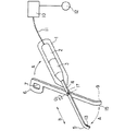
図1および図2は本発明の第1の実施形態を示している。図1に示されるように、本実施形態に係る超音波処置具は超音波振動子ユニット1を備えている。超音波振動子ユニット1には、超音波振動を発生する超音波振動子2と、超音波振動子2で発生した超音波振動を増幅するためのホーン3とが内蔵されている。超音波振動子2には、電線11を介して、電気エネルギを供給するジェネレータ10が電気的に接続されている。また、ジェネレータ10には、これを駆動させるための入力スイッチとして、例えばフットスイッチ12が接続されている。
【0015】
ホーン3には、ホーン3によって増幅された超音波振動を伝達する振動伝達部材としてのプローブ4が接続されている。プローブ4の先端部には、体組織を把持して処置するための第1の把持部5が形成されている。また、プローブ4には、軸体17を介して、ジョー6が回動可能に連結されている。ジョー6の先端部には、プローブ4の第1の把持部5との間で体組織を把持するための第2の把持部9が形成されている。また、ジョー6は、その第2の把持部9がプローブ4の第1の把持部5と対向する閉位置と、第2の把持部9が第1の把持部5から離間する開位置との間で、軸体17の中心軸O1を中心に図中矢印Aで示される方向に回動することができる。なお、ジョー6の手元側には、指掛け部7が設けられている。
【0016】
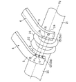
図2に詳細に示されるように、第1および第2の把持部5,9は、血管20,21の外周面に略沿う湾曲形状を成している。具体的には、第1の把持部5は、把持部5の下面を形成し且つ血管20,21の外周面に略沿って湾曲する支持面8と、把持部5の側面を形成し且つ第2の把持部9との間で組織を把持する把持面14とを有している。また、把持面14は、支持面8から略垂直に立ち上がる平面として形成されるとともに、湾曲形状の把持部5を形作るように支持面8の湾曲方向に沿って円弧状に延びている。また、同様に、第2の把持部9は、把持部9の下面を形成し且つ血管20,21の外周面に略沿って湾曲する支持面24と、把持部9の側面を形成し且つ第1の把持部5の把持面14との間で組織を把持する把持面16とを有している。また、把持面16は、支持面24から略垂直に立ち上がって把持面14と平行に対向可能な平面として形成されるとともに、湾曲形状の把持部9を形作るように支持面24の湾曲方向に沿って円弧状に延びている。
【0017】
第1の把持部5の把持面14には、組織を保持する保持手段の一方側を構成する複数(本実施形態では3つ)の凸部13が形成されている。これらの凸部13は、把持面14の延在方向に沿って互いに所定の間隔をもって配置されている。また、第2の把持部9の把持面16には、組織を保持する保持手段の他方側を構成する複数(本実施形態では3つ)の凹部15が形成されている。これらの凹部15は、把持面16の延在方向に沿って互いに所定の間隔をもって配置されるとともに、ジョー6が閉位置に回動された際に対応する凸部13と係合するようになっている。
【0018】
次に、上記構成の超音波処置具によって血管を吻合処置する場合について説明する。
【0019】
まず、超音波振動子ユニット1を一方の手で保持し、その手の親指等をジョー6の指掛け部7に引掛ける。次に、この状態で、図2に示されるように、プローブ4の第1の把持部5(具体的には、把持部5の支持面8)を吻合される一方側の血管20の外壁に沿わせるとともに、ジョー6の第2の把持部9(具体的には、把持部9の支持面24)を吻合される他方側の血管21の外壁に沿わせる。そして、その状態で、今度は、凸部13および凹部15の位置で、各血管20,21の吻合部の外壁22,23を図示しない把持具(例えば、ピンセット)によってめくり上げるとともに、そのめくり上げた状態で、指掛け部7に掛けている指を動かしてジョー6を閉位置へと移動させる。この操作により、ジョー6は、軸体17の中心軸O1を中心として図中矢印Aで示される方向に回動され、第1および第2の把持部5,9の把持面14,16間で、めくり上げられた血管20,21の外壁22,23が挟まれる。この時、凸部13と凹部15とが互いに係合されるため、めくり上げられている血管20,21の外壁22,23は、把持面14,16上でずれることなく挟持(保持)される。
【0020】
このようにして、めくり上げられた各血管20,21の外壁22,23を把持面14,16間で挟持したら、今度は、入力スイッチ12を操作してジェネレータ10を駆動する。これにより、ジェネレータ10によって生じる電気エネルギが、電線11を介して超音波振動子2に伝達され、振動エネルギへと変換される。この振動エネルギは、ホーン3によって増幅されつつプローブ4によって伝達され(矢印B方向の振動となって伝達され)、プローブ4の先端部に位置する第1の把持部5に供給される。したがって、第1の把持部5の把持面14と第2の把持部9の把持面16との間で摩擦熱が発生し、把持面14,16間に挟持されている血管20,21の外壁22,23が凝固癒着される。その後、血管20,21をその中心軸02回りに回転させて、同様の作業を数回繰り返せば、血管20,21の端々吻合が完了する。
【0021】
なお、第1および第2の把持部5,9の先端部分とその先端部分に設けられた一対の凸部13aおよび凹部15aのみを用いて同様の操作を行なえば、一方側の血管の側壁に形成された穴に他方側の血管の端面を吻合するいわゆる側端吻合を行なうこともできる。
【0022】
以上説明したように、本実施形態の超音波処置具は、超音波振動によって血管を凝固吻合するため、縫合糸を用いて血管吻合を行なう場合に比べ、手術時間の短縮および手術の簡略化を図ることができるとともに、端々吻合のみならず側端吻合にも適用できる。また、術後に血管内に異物が残らないため、良好な血流状態を維持できる。
【0023】
また、本実施形態の超音波処置具は、体組織を把持するための把持部5,9が湾曲形状を成しているため、血管20,21の周方向に沿う広い範囲で吻合部に対し一度に振動エネルギを与えることができる。そのため、従来の超音波処置具に比べ、凝固吻合完了までに要する把持回数が格段に減少し、手術時間の短縮および術者の疲労軽減を図ることができる。
【0024】
また、本実施形態の超音波処置具は、体組織を保持するための保持手段13,15を把持部5,9の把持面14,16に有している。そのため、体組織を把持面14,16上でずれることなく挟持(保持)でき、より確実な血管吻合を達成できる。
【0025】
図3〜図6は本発明の第2の実施形態を示している。なお、本実施形態において、第1の実施形態と共通する構成要素については、同一符号を付してその説明を省略する。
【0026】
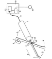
図3に示されるように、本実施形態の超音波処置具は、プローブ4に対するジョー6の相対的な回転角を検出する回転角検出素子(例えば、ロータリーエンコーダ)30を有している。この回転検出素子30は、ジョー6をプローブ4に対して回動可能に支持する軸体17に設けられており、ジェネレータ10の内部に設けられた出力制御部31に電気的に接続されている。
【0027】
出力制御部31は、エネルギ出力部32に接続されるとともに、血管20,21の外壁22,23の厚さに対応した出力レベル(血管外壁22,23を凝固癒着するのに必要かつ十分な出力レベル)が記憶されたデータメモリを搭載しており、回転角検出素子30から送られるジョー6の回転角信号に基づいて把持部5,9によって把持される血管外壁22,23の厚さを判定し、その厚さに応じた電気エネルギがエネルギ出力部32から出力されるようにエネルギ出力部32の駆動を制御する。
【0028】
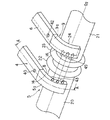
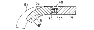
図4および図5に詳しく示されるように、プローブ4の先端部には、ビス40を介して、第1の把持部5を形成する湾曲状の第1の把持部材5aが着脱自在に取り付けられている。具体的には、プローブ4の先端部に係合穴37が形成され、この係合穴37に把持部材5aの挿入部39が挿入されるとともに、挿入部39がビス40を介してプローブ4に着脱自在に取り付けられている。また、プローブ4側と同様の形態で、ジョー6の先端部には、ビス42を介して、第2の把持部9を形成する湾曲状の第2の把持部材9aが着脱自在に取り付けられている。
【0029】
第1の把持部材5aは、その曲率半径がRに設定されており、把持部材5aの下面を形成し且つ血管20,21の外周面に略沿って湾曲する支持面8と、把持部材5aの側面を形成し且つ第2の把持部材9aとの間で組織を把持する把持面14とを有している。また、把持面14は、支持面8から略垂直に立ち上がる平面として形成されるとともに、湾曲形状の把持部材5aを形作るように支持面8の湾曲方向に沿って円弧状に延びている。
【0030】
同様に、第2の把持部材9aは、その曲率半径がRに設定されており、把持部材9aの下面を形成し且つ血管20,21の外周面に略沿って湾曲する支持面24と、把持部材9aの側面を形成し且つ第1の把持部材5aの把持面14との間で組織を把持する把持面16とを有している。また、把持面16は、支持面24から略垂直に立ち上がって把持面14と平行に対向可能な平面として形成されるとともに、湾曲形状の把持部材9aを形作るように支持面24の湾曲方向に沿って円弧状に延びている。
【0031】
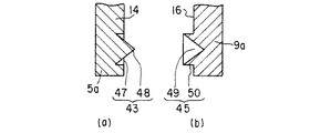
第1の把持部5の把持面14には、組織を保持する保持手段の一方側を構成する複数(本実施形態では3つ)の凸部43が形成されている。これらの凸部43は、把持面14の延在方向に沿って互いに所定の間隔をもって配置されている。また、第2の把持部9の把持面16には、組織を保持する保持手段の他方側を構成する複数(本実施形態では3つ)の凹部45が形成されている。これらの凹部45は、把持面16の延在方向に沿って互いに所定の間隔をもって配置されるとともに、ジョー6が閉位置に回動された際に対応する凸部43と係合するようになっている。
【0032】
図6に詳しく示されるように、凸部43は、その先端が鋭角的に尖った突起部48と、突起部48の外周にわたってドーナツ状に陥没した陥凹部47とから構成されている。一方、凹部45は、突起部48と係合可能で且つ円錐状に陥没した陥凹部49と、陥凹部49を外側から取り囲むように形成され且つ陥凹部47と係合可能な突起部50とから構成されている。なお、突起部50は、その先端が鋭角的に尖っている。
【0033】
次に、上記構成の超音波処置具によって血管を吻合処置する場合について説明する。
【0034】
まず、超音波振動子ユニット1を一方の手で保持し、その手の親指等をジョー6の指掛け部7に引掛ける。次に、この状態で、図4に示されるように、プローブ4の第1の把持部5(具体的には、把持部材5aの支持面8)を吻合される一方側の血管20の外壁に沿わせるとともに、ジョー6の第2の把持部9(具体的には、把持部材9aの支持面24)を吻合される他方側の血管21の外壁に沿わせる。そして、その状態で、今度は、凸部43および凹部45の位置で、各血管20,21の吻合部の外壁22,23を図示しない把持具(例えば、ピンセット)によってめくり上げ、外壁22を凸部43の突起部48の尖った部分に押し当てるとともに、外壁23を凹部45の突起部50の尖った部分に押し当てる。これにより、血管外壁22が凸部43に仮固定されるとともに、外壁23が凹部45に仮固定される。次に、この仮固定状態のまま、指掛け部7に掛けている指を動かしてジョー6を閉位置へと移動させる。この操作により、ジョー6は、軸体17の中心軸O1を中心として図中矢印Aで示される方向に回動され、第1および第2の把持部材5a,9aの把持面14,16間で、めくり上げられた血管20,21の外壁22,23が挟まれる。この時、凸部43と凹部45とが互いに係合されるため、めくり上げられている血管20,21の外壁22,23は、把持面14,16上でずれることなく挟持(保持)される。
【0035】
このようにして、めくり上げられた各血管20,21の外壁22,23を把持面14,16間で挟持したら、今度は、入力スイッチ12を操作する。これにより、ジェネレータ10の出力制御部31に駆動信号が入力されるとともに、ジョー6の回転角信号が回転角検出素子30から出力制御部31に入力される。出力制御部31は、回転角検出素子30から送られるジョー6の回転角信号に基づいて、把持部5,9によって把持される血管外壁22,23の厚さを判定し、その厚さに適した出力レベル(電気エネルギ)をデータメモリに記憶されている情報から読み取って設定するとともに、その設定された電気エネルギがエネルギ出力部32から出力されるようにエネルギ出力部32の駆動を制御する。
【0036】
エネルギ出力部32から出力される電気エネルギは、電線11を介して超音波振動子2に伝達され、振動エネルギへと変換される。この振動エネルギは、ホーン3によって増幅されつつプローブ4によって伝達され(矢印B方向の振動となって伝達され)、プローブ4の先端部に位置する第1の把持部材5aに供給される。したがって、第1の把持部材5aの把持面14と第2の把持部材9aの把持面16との間で摩擦熱が発生し、把持面14,16間に挟持されている血管20,21の外壁22,23が凝固癒着される。その後、血管20,21をその中心軸02回りに回転させて、同様の作業を数回繰り返せば、血管20,21の端々吻合が完了する。
【0037】
なお、吻合する血管の径(R’)と第1および第2の把持部材5a,9aの曲率半径(R)とが大きく異なる場合には、図示しない工具等を用いてネジ40,42を外して、プローブ4およびジョー6から第1および第2の把持部材5a,9aを取り外すとともに、代わって、吻合する血管の径(R’)と略一致する曲率半径R’の第3および第4の把持部材5b,9bをプローブ4およびジョー6に取付ければ良い(図5参照…把持部材9bは図示されていない)。
【0038】
以上説明したように、本実施形態の超音波処置具は、体組織を把持するための把持部5,9が湾曲形状を成しており、また、体組織を保持するための保持手段43,45が把持部5,9の把持面14,16に設けられているため、第1の実施形態と同様の作用効果を得ることができる。特に、本実施形態では、把持面14,16間で血管外壁22,23を把持する前に、保持手段43,45の突起部を用いて各把持面14,16に血管外壁22,23を仮固定できるため、把持時に血管外壁22,23が滑ることを防止でき、より確実な凝固癒着が可能となる。
【0039】
また、本実施形態の超音波処置具では、吻合する血管壁の厚さに適した出力レベルの超音波エネルギが第1の把持部5に供給されるため、凝固癒着が不十分であったり、逆に、血管壁を焦がしすぎるといった事態を防止でき、より確実な血管吻合が可能となる。
【0040】
また、本実施形態の超音波処置具では、プローブ4およびジョー6に対して第1および第2の把持部材5a,9aが着脱自在に取り付けられているため、吻合される血管の径に最適な曲率半径の把持部材を選択して使用することができる。
【0041】
なお、本実施形態においては、吻合される血管壁の厚さを知るために、ジョー6の回転角が検出されているが、ジョー6もしくはプローブ4の先端部に圧力素子を設けることによって血管壁の厚さが検出されても良い。
【0042】
図7および図8は本発明の第3の実施形態を示している。なお、本実施形態において、第1の実施形態と共通する構成要素については、同一符号を付してその説明を省略する。
【0043】
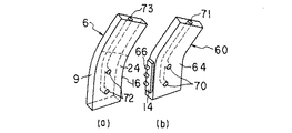
図7に示されるように、超音波振動子ユニット1には、プローブカバー60が一体的に取付けられている。プローブカバー60の内側には、ホーン3に接続されたプローブ4が配設されている。また、プローブカバー60の先端部は、プローブ4の先端部とともに湾曲しており、ジョー6の第2の把持部9との間で体組織を把持する第1の把持部5を形成している。具体的には、プローブカバー60の先端部は、下面を形成し且つ血管20,21の外周面に略沿って湾曲する支持面64と、側面を形成し且つ第2の把持部9との間で組織を把持する把持面63とを有している。また、把持面63は、支持面64から略垂直に立ち上がる平面として形成されるとともに、支持面64の湾曲方向に沿って円弧状に延びている。
【0044】
プローブ4の把持面14は、プローブカバー60の把持面63で、外部に露出されている。この露出する把持面14には、組織を保持する保持手段の一方側を構成する複数(本実施形態では3つ)の凸部66が形成されている。これらの凸部66は、把持面14の延在方向に沿って互いに所定の間隔をもって配置されている。また、第2の把持部9の把持面16には、組織を保持する保持手段の他方側を構成する複数(本実施形態では3つ)の凹部67が形成されている。これらの凹部67は、把持面16の延在方向に沿って互いに所定の間隔をもって配置されるとともに、ジョー6が閉位置に回動された際に対応する凸部66と係合するようになっている。
【0045】
図8に示されるように、プローブカバー60の支持面64には複数の穴70が形成されている。これらの穴70はカバー60の内部で中空管71と結合されており、中空管71は図示しないパイプ部材を介して吸引ポンプ(図示せず)に接続されている。一方、ジョー6の第2の把持部9の支持面24にも複数の穴72が形成されている。これらの穴72はジョー6の内部で中空管73と結合されており、中空管73は図示しないパイプ部材を介して吸引ポンプ(図示せず)に接続されている。
【0046】
このような構成では、吻合される血管20,21の外壁に第1の把持部5および第2の把持部9を沿わせた際、プローブカバー60およびジョー62に設けられた穴部70および72に作用する吸引圧によって、血管20,21の外壁が支持面24,64に吸着される。そのため、血管外壁22,23の一部分をめくり上げる作業がより容易となる。
【0047】
また、プローブ4をプローブカバー60の内部に収納し、プローブ4の把持面14のみを外部に露出させているため、振動エネルギが血管の不要な部分に伝わることを防止できる。そのため、血管吻合時に誤って血管を閉塞してしまうといった事態を確実に防止できる。
【0048】
なお、以上説明してきた技術内容によれば、以下に示すような各種の構成が得られる。
【0049】
1.超音波振動を発生する超音波振動子と、
超音波振動子に接続される振動伝達部材と、
振動伝達部材に接続される第1の把持部と、
第1の把持部に対峙して可動自在であり、前記第1の把持部との間で生体組織を把持する第2の把持部とを有する超音波処置具において、
前記第1および第2の把持部の一端が略円弧形状の湾曲部からなるとともに、両把持部の対峙する面に生体組織を保持する保持部材を設けたことを特徴とする超音波処置具。
【0050】
2.第1の把持部および第2の把持部によって把持される生体組織の厚さを検出する検出手段と、この検出手段による検出結果に基づいて超音波振動子の出力を制御する制御手段とを備えていることを特徴とする第1項に記載の超音波処置具。
【0051】
3.前記湾曲部が第1の把持部および第2の把持部に対して着脱可能に取り付けられていることを特徴とする第1項に記載の超音波処置具。
4.前記保持部材が鋭角形状からなることを特徴とする第1項に記載の超音波処置具。
5.前記検出手段は、第1の把持部と第2の把持部の相対位置関係を検出することを特徴とする第2項に記載の超音波処置具。
【0052】
6.前記検出手段が角度検出手段からなることを特徴とする第2項に記載の超音波処置具。
7.前記湾曲部に1つ以上の穴部を設けるとともに、この穴部を吸引装置に接続可能にしたことを特徴とする第1項に記載の超音波処置具。
8.前記第1の把持部を被うカバー部材が設けられていることを特徴とする第1項に記載の超音波処置具。
9.前記第1の把持部を被うカバー部材を設けるとともに、第1の把持部に設けられた湾曲部が前記カバー部材から外部に露出していることを特徴とする第1項に記載の超音波処置具。
【0053】
【発明の効果】
以上説明したように、本発明の超音波処置具によれば、血管の吻合を短時間で簡単且つ正確に行なうことができるとともに、術後の状態を良好に維持でき、端々吻合のみならず側端吻合にも適用できる。
【図面の簡単な説明】
【図1】本発明の第1の実施形態に係る超音波処置具の概略斜視図である。
【図2】図1の超音波処置具の把持部によって血管を吻合する状態を示す拡大斜視図である。
【図3】本発明の第2の実施形態に係る超音波処置具の概略斜視図である。
【図4】図3の超音波処置具の把持部によって血管を吻合する状態を示す拡大斜視図である。
【図5】図4のA−A線に沿う断面図である。
【図6】(a)はプローブの把持面に設けられた保持手段の断面図、(b)はジョーの把持面に設けられた保持手段の断面図である。
【図7】本発明の第3の実施形態に係る超音波処置具の把持部の斜視図である。
【図8】(a)はジョーの把持部を支持面側から見た斜視図、(b)はプローブカバーの先端部をその支持面側から見た斜視図である。
【符号の説明】
2…超音波振動子
4…プローブ(振動伝達部材)
5…第1の把持部
6…ジョー
9…第2の把持部
13,43,66…凸部(保持手段)
15,45,67…凹部(保持手段)[0001]
BACKGROUND OF THE INVENTION
The present invention relates to an ultrasonic treatment tool for treating body tissue with ultrasonic vibration energy, and more particularly to an ultrasonic treatment tool capable of anastomosing using ultrasonic waves while grasping a cut blood vessel.
[0002]
[Prior art]
Vascular anastomosis is an indispensable procedure in tissue transplantation and organ transplantation. In particular, in recent years when the development of surgical techniques and instruments is remarkable, the diameter of blood vessels to be anastomosed is also miniaturized, and more reliable engraftment is required.
[0003]
In the blood vessel anastomosis, in order to secure the blood flow after the anastomosis, the cut surfaces of the blood vessels are securely stitched one by one with the suture thread. Therefore, the surgeon is forced to fatigue a great deal of time and spirit. Therefore, at present, various blood vessel anastomosis assisting tools are provided for the purpose of reducing the anastomosis work.
[0004]
For example, Japanese Patent Application Laid-Open No. 6-123391 discloses a blood vessel anastomosis connector that facilitates a threading operation of a suture thread on a blood vessel by preventing inward deformation of a blood vessel wall during the suturing operation. This blood vessel anastomosis connector is formed as a cylindrical member made of a bioabsorbable material, and is inserted into each end portion of two blood vessels to be joined to each other across both blood vessels. The two blood vessels connected by the blood vessel anastomosis connector have their intima protruding outward and abutted against each other, and the end surfaces of the abutted intima are stitched together with a suture thread.
[0005]
Japanese Patent Application Laid-Open Nos. 8-19547 and 8-19597 disclose that both blood vessels are attached to the outer peripheral surface of each end of two blood vessels to be joined and are connected to each other. A pair of vascular anastomoses that can be anastomosed by action is disclosed. These blood vessel anastomoses each have a coupling pin, a pin insertion hole, and a through hole into which a blood vessel is inserted. The coupling pin of the first vascular anastomosis instrument in a state where the first vascular anastomosis instrument is fitted on the outer circumference of the end of the one blood vessel and the second vascular anastomosis instrument is fitted on the outer circumference of the other blood vessel. Is inserted into the pin insertion hole of the second vascular anastomosis instrument, and when the coupling pin of the second vascular anastomosis instrument is inserted into the pin insertion hole of the first vascular anastomosis instrument, the first and second vascular anastomosis instruments Are connected to each other, and the two blood vessels to which the vascular anastomosis tool is attached are anastomosed. In JP-A-8-19597, the vascular anastomosis instrument is formed of a bioabsorbable material.
[0006]
Japanese Patent Application No. 9-355390 discloses an ultrasonic treatment instrument that includes a grasping portion capable of grasping a body tissue and incises and coagulates the body tissue grasped by the grasping portion by heat energy of ultrasonic vibration. ing.
[0007]
[Problems to be solved by the invention]
However, in the blood vessel anastomosis using the blood vessel anastomosis connector disclosed in Japanese Patent Laid-Open No. 6-123391, the blood vessels are sutured together by the suture thread, so that the number of times is increased from several times to 10 times for one blood vessel. A degree of threading is required. Therefore, the anastomosis work is troublesome and the operation time becomes long. In addition, since the blood vessel anastomosis connector remains as a foreign substance in the blood vessel until it is absorbed by the living body, the blood flow state immediately after the operation is extremely worse than when the blood vessel anastomosis connector is not used. . For this reason, there is a possibility that the survival rate of the transplanted tissue is reduced. In addition, the possibility increases as the diameter of the blood vessel becomes smaller. The connector for blood vessel anastomosis is applicable only to so-called end-to-end anastomosis for anastomosing the end portions (end surfaces) of blood vessels, and the end surface of the other blood vessel is anastomosed to the hole formed in the side wall of the one blood vessel It is not applicable to so-called side-end anastomosis.
[0008]
On the other hand, in the technique disclosed in Japanese Patent Application Laid-Open No. 8-19547, the vascular anastomosis tool is attached to the outer periphery of the blood vessel, so that the vascular anastomosis tool protrudes from the skin particularly when the surgical target site is a body surface site. There is a problem such as. In addition, there is a problem that the vascular anastomosis device itself remains in the body as a foreign object after the operation. The blood vessel anastomosis device can be applied only to so-called end-to-end anastomosis in which the end portions (end surfaces) of the blood vessels are anastomosed. It cannot be applied to so-called side end anastomosis.
[0009]
Further, in the technique disclosed in Japanese Patent Application Laid-Open No. 8-19597, the vascular anastomosis instrument is formed of a bioabsorbable material. Therefore, the vascular anastomosis instrument is absorbed by the living body after a predetermined period of time, and after bioabsorption. The blood flow is secured by adhesion between blood vessels. However, the problem similar to the technique disclosed in JP-A-8-19547 occurs until the vascular anastomosis device is completely absorbed by the living body. In addition, since the time until adhesion varies depending on the diameter of the blood vessel and the state of blood flow, the target blood vessel is not always securely adhered when the vascular anastomosis device is completely absorbed by the living body. If it is not firmly attached, blood leaks in the body. Of course, in order to avoid such a situation, it may be possible to lengthen the time until the bioabsorbable material is absorbed by the living body, but in that case, as a matter of course, the blood vessel anastomosis protrudes from the skin. The period (or the period during which the vascular anastomosis device itself remains in the body as a foreign object) also becomes longer. Further, as in JP-A-8-19547, the vascular anastomosis instrument cannot be applied to the side end anastomosis.
[0010]
Further, in the technique disclosed in Japanese Patent Application No. 9-355390, blood vessels are coagulated and adhered in a short time by the thermal energy of ultrasonic vibration without using sutures or foreign matters. However, it is difficult to grasp the end portions of the blood vessel without shifting each other by the grasping portion. That is, in order to join the end faces of the blood vessels accurately without deviation, the surgeon is forced to fatigue a lot. Further, when blood vessels are displaced and coagulated and adhered, the state of blood flow is lowered, blood is not sufficiently supplied to the transplanted tissue, and the survival rate of the transplanted tissue is reduced.
[0011]
The present invention has been made by paying attention to the above-mentioned circumstances, and the object of the present invention is to be able to easily and accurately perform an anastomosis of blood vessels in a short time and to maintain a good post-operative condition. An object of the present invention is to provide an ultrasonic treatment device that can be applied not only to anastomosis but also to side-end anastomosis.
[0012]
[Means for Solving the Problems]
The present invention relates to an ultrasonic transducer that generates ultrasonic vibrations, a vibration transmission member that is connected to the ultrasonic transducers and transmits ultrasonic vibrations generated by the ultrasonic transducers, and a tip of the vibration transmission member The living tissue to be treated is treated by the vibration energy provided and transmitted to the part So on the side A first grip portion having a first grip surface and a second grip surface facing the first grip surface; On the side Possess ,in front A second gripping part supported movably in a direction for gripping the biological tissue of two parts that are anastomosed between the first gripping face and the second gripping face; the first gripping part and the second gripping part Grip part Provided on the bottom of each Having a support surface; Each supporting surface abuts on the outer surface other than the anastomotic site in the corresponding biological tissue, Each support surface is Corresponding Curved with a predetermined radius of curvature along the outer circumferential direction of the living tissue, and pressing the corresponding living tissue on each supporting surface to the first gripping portion and the second gripping portion. More each Holding means for holding the corresponding living tissue, and the support surface of the first gripping portion and the support surface of the second gripping portion are Each student Abutting the outer periphery of the body tissue Each student The body tissue is held by the first gripping portion and the second gripping portion, and then the second gripping portion is moved toward the first gripping portion to move the body tissue between the first gripping surface and the second gripping surface. Each student An ultrasonic treatment device characterized by grasping a body tissue and anastomosing the two.
[0013]
DETAILED DESCRIPTION OF THE INVENTION
Hereinafter, embodiments of the present invention will be described with reference to the drawings.
[0014]
1 and 2 show a first embodiment of the present invention. As shown in FIG. 1, the ultrasonic treatment instrument according to the present embodiment includes an ultrasonic transducer unit 1. The ultrasonic transducer unit 1 includes an
[0015]
The horn 3 is connected to a
[0016]
As shown in detail in FIG. 2, the first and second grasping
[0017]
A plurality (three in this embodiment) of
[0018]
Next, the case where the blood vessel is anastomosed with the ultrasonic treatment instrument having the above-described configuration will be described.
[0019]
First, the ultrasonic transducer unit 1 is held with one hand, and the thumb or the like of the hand is hooked on the finger hooking portion 7 of the
[0020]
When the
[0021]
If the same operation is performed using only the distal end portions of the first and second
[0022]
As described above, since the ultrasonic treatment instrument of this embodiment coagulates and anastomoses blood vessels by ultrasonic vibration, the operation time is shortened and the operation is simplified compared to the case of performing blood vessel anastomoses using sutures. It can be applied to not only end-to-end anastomosis but also side-to-end anastomosis. In addition, since no foreign matter remains in the blood vessel after the operation, a good blood flow state can be maintained.
[0023]
In addition, since the grasping
[0024]
In addition, the ultrasonic treatment instrument of the present embodiment has holding means 13 and 15 for holding body tissue on the holding surfaces 14 and 16 of the holding
[0025]
3 to 6 show a second embodiment of the present invention. Note that in this embodiment, the same reference numerals are given to components common to the first embodiment, and description thereof is omitted.
[0026]
As shown in FIG. 3, the ultrasonic treatment instrument of the present embodiment includes a rotation angle detection element (for example, a rotary encoder) 30 that detects a relative rotation angle of the
[0027]
The
[0028]
As shown in detail in FIGS. 4 and 5, a curved first gripping member 5 a forming the first
[0029]
The radius of curvature of the first gripping member 5a is set to R, the
[0030]
Similarly, the radius of curvature of the second gripping member 9a is set to R, the
[0031]
A plurality (three in this embodiment) of
[0032]
As shown in detail in FIG. 6, the
[0033]
Next, the case where the blood vessel is anastomosed with the ultrasonic treatment instrument having the above-described configuration will be described.
[0034]
First, the ultrasonic transducer unit 1 is held with one hand, and the thumb or the like of the hand is hooked on the finger hooking portion 7 of the
[0035]
When the
[0036]
The electrical energy output from the
[0037]
When the diameter (R ′) of the blood vessel to be anastomosed and the curvature radii (R) of the first and second gripping members 5a and 9a are greatly different, the
[0038]
As described above, in the ultrasonic treatment instrument according to the present embodiment, the holding
[0039]
Further, in the ultrasonic treatment instrument of the present embodiment, since the ultrasonic energy of the output level suitable for the thickness of the blood vessel wall to be anastomosed is supplied to the first
[0040]
In the ultrasonic treatment instrument of the present embodiment, the first and second gripping members 5a and 9a are detachably attached to the
[0041]
In this embodiment, the rotation angle of the
[0042]
7 and 8 show a third embodiment of the present invention. Note that in this embodiment, the same reference numerals are given to components common to the first embodiment, and description thereof is omitted.
[0043]
As shown in FIG. 7, a
[0044]
The gripping
[0045]
As shown in FIG. 8, a plurality of
[0046]
In such a configuration, the
[0047]
Further, since the
[0048]
In addition, according to the technical content demonstrated above, the various structures as shown below are obtained.
[0049]
1. An ultrasonic transducer that generates ultrasonic vibrations;
A vibration transmitting member connected to the ultrasonic transducer;
A first grip portion connected to the vibration transmitting member;
In the ultrasonic treatment instrument having a second grasping portion that is movable in opposition to the first grasping portion and grasps the living tissue with the first grasping portion,
One end of the said 1st and 2nd holding part consists of a substantially arc-shaped curved part, and the holding member holding a biological tissue was provided in the surface which both holding parts oppose, The ultrasonic treatment tool characterized by the above-mentioned.
[0050]
2. Detection means for detecting the thickness of the living tissue grasped by the first grasping section and the second grasping section, and control means for controlling the output of the ultrasonic transducer based on the detection result by the detection means. The ultrasonic treatment device according to item 1, wherein the ultrasonic treatment device is provided.
[0051]
3. 2. The ultrasonic treatment instrument according to claim 1, wherein the bending portion is detachably attached to the first grip portion and the second grip portion.
4). 2. The ultrasonic treatment instrument according to claim 1, wherein the holding member has an acute angle shape.
5. The ultrasonic treatment instrument according to
[0052]
6). The ultrasonic treatment instrument according to
7). The ultrasonic treatment instrument according to claim 1, wherein one or more holes are provided in the curved portion, and the holes can be connected to a suction device.
8). The ultrasonic treatment instrument according to claim 1, further comprising a cover member that covers the first gripping portion.
9. The ultrasonic wave according to claim 1, wherein a cover member that covers the first gripping portion is provided, and a curved portion provided in the first gripping portion is exposed to the outside from the cover member. Treatment tool.
[0053]
【The invention's effect】
As described above, according to the ultrasonic treatment instrument of the present invention, blood vessel anastomosis can be performed easily and accurately in a short time, and the postoperative condition can be maintained well, and not only the end-to-end anastomosis. It can also be applied to end anastomoses.
[Brief description of the drawings]
FIG. 1 is a schematic perspective view of an ultrasonic treatment apparatus according to a first embodiment of the present invention.
2 is an enlarged perspective view showing a state in which a blood vessel is anastomosed by a grasping portion of the ultrasonic treatment instrument in FIG. 1. FIG.
FIG. 3 is a schematic perspective view of an ultrasonic treatment apparatus according to a second embodiment of the present invention.
4 is an enlarged perspective view showing a state in which a blood vessel is anastomosed by a grasping portion of the ultrasonic treatment instrument in FIG. 3. FIG.
5 is a cross-sectional view taken along line AA in FIG.
6A is a cross-sectional view of the holding means provided on the gripping surface of the probe, and FIG. 6B is a cross-sectional view of the holding means provided on the gripping surface of the jaw.
FIG. 7 is a perspective view of a grip portion of an ultrasonic treatment apparatus according to a third embodiment of the present invention.
8A is a perspective view of the jaw gripping portion viewed from the support surface side, and FIG. 8B is a perspective view of the tip end portion of the probe cover viewed from the support surface side.
[Explanation of symbols]
2 ... Ultrasonic transducer
4. Probe (vibration transmission member)
5 ... 1st holding part
6 ... Joe
9 ... 2nd holding part
13, 43, 66 ... convex portion (holding means)
15, 45, 67 ... concave portion (holding means)
Claims (3)
前記超音波振動子に接続され、前記超音波振動子で発生する超音波振動を伝達する振動伝達部材と、
前記振動伝達部材の先端部に設けられ、伝達される振動エネルギによって処置対象の生体組織を処置するように側面に第1把持面を有した第1把持部と、
前記第1把持面に対峙する第2把持面を側面に有し、前記第1把持面と前記第2把持面との間で吻合する2つの部位の生体組織を把持する向きに移動自在に支持された第2の把持部と、
前記第1把持部および前記第2把持部の各々の底面に各々設けられた支持面を有し、各々の支持面は各々対応する生体組織における吻合部位以外の外表面と当接すると共に、各々の支持面は各々対応する生体組織の外周方向に沿って所定の曲率半径をもって湾曲してなり、各々の支持面で各々対応する生体組織を押さえて前記第1把持部および第2把持部により各々に対応する生体組織を保持する保持手段と、
を具備し、
前記第1把持部の支持面と第2把持部の支持面を前記各生体組織の外周に当接させて前記各生体組織を前記第1把持部および第2把持部に保持した上で前記第1把持部に向けて第2の把持部を移動して前記第1把持面と前記第2把持面との間で各生体組織を把持して両者を吻合するようにしたことを特徴とする超音波処置具。An ultrasonic transducer that generates ultrasonic vibrations;
A vibration transmitting member connected to the ultrasonic transducer and transmitting ultrasonic vibration generated by the ultrasonic transducer;
A first gripping portion provided at the tip of the vibration transmitting member and having a first gripping surface on a side surface so as to treat a living tissue to be treated with transmitted vibration energy;
A second gripping surface which faces the first gripping surface side, front Symbol movably in a direction to grip the living tissue of the two sites of anastomosis between a first gripping surface and said second gripping surface A supported second gripping portion;
Each of the first gripping portion and the second gripping portion has a support surface provided on each bottom surface, and each support surface is in contact with an outer surface of the corresponding living tissue other than the anastomosis site , support surface becomes curved with a predetermined radius of curvature along the outer circumferential direction of each corresponding biological tissue, and more each in the first grip and the second grip portion pressing the each corresponding biological tissue at each of the support surface Holding means for holding corresponding biological tissues,
Comprising
On holding the support surface and the first gripping portion of each of the living body tissue by contact and the second grip portion to the outer periphery of the support surface each raw material tissue of the second gripping portion of the first grip characterized in that so as to anastomosis both holding the respective raw material tissue between by moving the second gripping portion toward the first gripping portion and the first gripping surface and the second gripping surface Ultrasonic treatment tool.
Priority Applications (1)
| Application Number | Priority Date | Filing Date | Title |
|---|---|---|---|
| JP19445899A JP3911368B2 (en) | 1999-07-08 | 1999-07-08 | Ultrasonic treatment device |
Applications Claiming Priority (1)
| Application Number | Priority Date | Filing Date | Title |
|---|---|---|---|
| JP19445899A JP3911368B2 (en) | 1999-07-08 | 1999-07-08 | Ultrasonic treatment device |
Publications (2)
| Publication Number | Publication Date |
|---|---|
| JP2001017438A JP2001017438A (en) | 2001-01-23 |
| JP3911368B2 true JP3911368B2 (en) | 2007-05-09 |
Family
ID=16324910
Family Applications (1)
| Application Number | Title | Priority Date | Filing Date |
|---|---|---|---|
| JP19445899A Expired - Fee Related JP3911368B2 (en) | 1999-07-08 | 1999-07-08 | Ultrasonic treatment device |
Country Status (1)
| Country | Link |
|---|---|
| JP (1) | JP3911368B2 (en) |
Cited By (1)
| Publication number | Priority date | Publication date | Assignee | Title |
|---|---|---|---|---|
| EP3574856A1 (en) * | 2018-05-31 | 2019-12-04 | Covidien LP | Systems for ultrasonic vessel sealing |
Families Citing this family (3)
| Publication number | Priority date | Publication date | Assignee | Title |
|---|---|---|---|---|
| AT411216B (en) | 2002-01-25 | 2003-11-25 | Schubert Heinrich Dr | DEVICE FOR PRODUCING ANASTOMOSIS BETWEEN HOLLOW ORGANS |
| JP5546925B2 (en) * | 2010-03-30 | 2014-07-09 | 一史 舘 | Anastomosis instrument and anastomosis structure |
| US11266430B2 (en) * | 2016-11-29 | 2022-03-08 | Cilag Gmbh International | End effector control and calibration |
-
1999
- 1999-07-08 JP JP19445899A patent/JP3911368B2/en not_active Expired - Fee Related
Cited By (3)
| Publication number | Priority date | Publication date | Assignee | Title |
|---|---|---|---|---|
| EP3574856A1 (en) * | 2018-05-31 | 2019-12-04 | Covidien LP | Systems for ultrasonic vessel sealing |
| CN110547852A (en) * | 2018-05-31 | 2019-12-10 | 柯惠有限合伙公司 | Method and system for ultrasonic vessel sealing |
| US11540856B2 (en) | 2018-05-31 | 2023-01-03 | Covidien Lp | Methods and systems for ultrasonic vessel sealing |
Also Published As
| Publication number | Publication date |
|---|---|
| JP2001017438A (en) | 2001-01-23 |
Similar Documents
| Publication | Publication Date | Title |
|---|---|---|
| US20230390591A1 (en) | Surgical instruments | |
| EP3068490B1 (en) | Ultrasonic anastomosis instrument with piezoelectric sealing head | |
| EP3827768B1 (en) | Surgical instrument use indicator | |
| JP6965339B2 (en) | Ultrasound surgical instruments with replaceable blades for identification | |
| JP5372931B2 (en) | Improved surgical instrument | |
| EP1551321B1 (en) | Ultrasonic device for tissue coagulation | |
| AU730167B2 (en) | Ultrasonic clamp coagulator apparatus having dual rotational positioning | |
| JP2003527155A (en) | Multifunctional curved blade for use with ultrasonic surgical instruments | |
| AU8841598A (en) | Ultrasonic clamp coagulator apparatus having improved waveguide support member | |
| US20190008547A1 (en) | Features to couple acoustic drivetrain components in ultrasonic surgical instrument | |
| JP3911368B2 (en) | Ultrasonic treatment device | |
| JP2020533047A (en) | Electric surgical system for cutting and welding parenchymal organs | |
| JP3766520B2 (en) | Vascular anastomosis device | |
| US20070095355A1 (en) | Blood vessel treatment method using multi-degree-of-freedom forceps | |
| JP2002035001A (en) | Ultrasonic surgical instrument | |
| WO2024079744A1 (en) | An ultrasonic surgical device | |
| JP4422243B2 (en) | Ultrasonic treatment device | |
| JP2001037770A (en) | Ultrasonic treatment implement | |
| JP2003061973A (en) | Ultrasonic tissue fusing apparatus | |
| JPH0723974A (en) | Ultrasonic treatment apparatus | |
| JP3791878B2 (en) | Ultrasonic suture device | |
| JP2001037771A (en) | Ultrasonic treatment device | |
| JPH0428568Y2 (en) | ||
| JP2005074014A (en) | Trocar system | |
| JP3768827B2 (en) | Ultrasonic surgical device |
Legal Events
| Date | Code | Title | Description |
|---|---|---|---|
| A977 | Report on retrieval |
Free format text: JAPANESE INTERMEDIATE CODE: A971007 Effective date: 20051027 |
|
| A131 | Notification of reasons for refusal |
Free format text: JAPANESE INTERMEDIATE CODE: A131 Effective date: 20051122 |
|
| A521 | Written amendment |
Free format text: JAPANESE INTERMEDIATE CODE: A523 Effective date: 20060123 |
|
| A131 | Notification of reasons for refusal |
Free format text: JAPANESE INTERMEDIATE CODE: A131 Effective date: 20060725 |
|
| A521 | Written amendment |
Free format text: JAPANESE INTERMEDIATE CODE: A523 Effective date: 20060920 |
|
| TRDD | Decision of grant or rejection written | ||
| A01 | Written decision to grant a patent or to grant a registration (utility model) |
Free format text: JAPANESE INTERMEDIATE CODE: A01 Effective date: 20070123 |
|
| A61 | First payment of annual fees (during grant procedure) |
Free format text: JAPANESE INTERMEDIATE CODE: A61 Effective date: 20070129 |
|
| FPAY | Renewal fee payment (event date is renewal date of database) |
Free format text: PAYMENT UNTIL: 20110202 Year of fee payment: 4 |
|
| FPAY | Renewal fee payment (event date is renewal date of database) |
Free format text: PAYMENT UNTIL: 20110202 Year of fee payment: 4 |
|
| FPAY | Renewal fee payment (event date is renewal date of database) |
Free format text: PAYMENT UNTIL: 20120202 Year of fee payment: 5 |
|
| FPAY | Renewal fee payment (event date is renewal date of database) |
Free format text: PAYMENT UNTIL: 20120202 Year of fee payment: 5 |
|
| FPAY | Renewal fee payment (event date is renewal date of database) |
Free format text: PAYMENT UNTIL: 20130202 Year of fee payment: 6 |
|
| FPAY | Renewal fee payment (event date is renewal date of database) |
Free format text: PAYMENT UNTIL: 20140202 Year of fee payment: 7 |
|
| LAPS | Cancellation because of no payment of annual fees |