JP3911033B2 - Ultrasonic interlocking device - Google Patents
Ultrasonic interlocking device Download PDFInfo
- Publication number
- JP3911033B2 JP3911033B2 JP53771298A JP53771298A JP3911033B2 JP 3911033 B2 JP3911033 B2 JP 3911033B2 JP 53771298 A JP53771298 A JP 53771298A JP 53771298 A JP53771298 A JP 53771298A JP 3911033 B2 JP3911033 B2 JP 3911033B2
- Authority
- JP
- Japan
- Prior art keywords
- brake
- ultrasonic
- transmission rod
- transmission
- assembly
- Prior art date
- Legal status (The legal status is an assumption and is not a legal conclusion. Google has not performed a legal analysis and makes no representation as to the accuracy of the status listed.)
- Expired - Fee Related
Links
- 230000005540 biological transmission Effects 0.000 claims description 95
- 239000012636 effector Substances 0.000 claims description 32
- 238000009434 installation Methods 0.000 claims description 15
- 230000007246 mechanism Effects 0.000 claims description 15
- 210000001015 abdomen Anatomy 0.000 claims description 9
- 230000003213 activating effect Effects 0.000 claims description 5
- 230000004044 response Effects 0.000 claims description 4
- 210000001519 tissue Anatomy 0.000 description 25
- 239000000463 material Substances 0.000 description 14
- 230000033001 locomotion Effects 0.000 description 12
- 238000000034 method Methods 0.000 description 9
- 230000035515 penetration Effects 0.000 description 9
- 238000010586 diagram Methods 0.000 description 8
- 230000008569 process Effects 0.000 description 7
- 239000004812 Fluorinated ethylene propylene Substances 0.000 description 4
- XUIMIQQOPSSXEZ-UHFFFAOYSA-N Silicon Chemical compound [Si] XUIMIQQOPSSXEZ-UHFFFAOYSA-N 0.000 description 4
- 229920009441 perflouroethylene propylene Polymers 0.000 description 4
- 229920001343 polytetrafluoroethylene Polymers 0.000 description 4
- 239000004810 polytetrafluoroethylene Substances 0.000 description 4
- 210000004027 cell Anatomy 0.000 description 3
- 238000005345 coagulation Methods 0.000 description 3
- 230000015271 coagulation Effects 0.000 description 3
- 238000001514 detection method Methods 0.000 description 3
- 208000014674 injury Diseases 0.000 description 3
- 230000000149 penetrating effect Effects 0.000 description 3
- 102000004169 proteins and genes Human genes 0.000 description 3
- 108090000623 proteins and genes Proteins 0.000 description 3
- 239000007787 solid Substances 0.000 description 3
- 230000008733 trauma Effects 0.000 description 3
- 229910000838 Al alloy Inorganic materials 0.000 description 2
- 229910001069 Ti alloy Inorganic materials 0.000 description 2
- 229920004738 ULTEM® Polymers 0.000 description 2
- 230000004913 activation Effects 0.000 description 2
- 210000004204 blood vessel Anatomy 0.000 description 2
- 238000010276 construction Methods 0.000 description 2
- 239000011162 core material Substances 0.000 description 2
- 230000008878 coupling Effects 0.000 description 2
- 238000010168 coupling process Methods 0.000 description 2
- 238000005859 coupling reaction Methods 0.000 description 2
- 238000006073 displacement reaction Methods 0.000 description 2
- 230000000694 effects Effects 0.000 description 2
- 230000008713 feedback mechanism Effects 0.000 description 2
- 238000003780 insertion Methods 0.000 description 2
- 230000037431 insertion Effects 0.000 description 2
- 238000012986 modification Methods 0.000 description 2
- 230000004048 modification Effects 0.000 description 2
- 239000004033 plastic Substances 0.000 description 2
- 229920003023 plastic Polymers 0.000 description 2
- -1 polytetrafluoroethylene Polymers 0.000 description 2
- 238000000926 separation method Methods 0.000 description 2
- 239000010935 stainless steel Substances 0.000 description 2
- 229910001220 stainless steel Inorganic materials 0.000 description 2
- 238000001356 surgical procedure Methods 0.000 description 2
- 238000002604 ultrasonography Methods 0.000 description 2
- 102000008186 Collagen Human genes 0.000 description 1
- 108010035532 Collagen Proteins 0.000 description 1
- 102000008934 Muscle Proteins Human genes 0.000 description 1
- 108010074084 Muscle Proteins Proteins 0.000 description 1
- 239000004743 Polypropylene Substances 0.000 description 1
- 229910000831 Steel Inorganic materials 0.000 description 1
- RTAQQCXQSZGOHL-UHFFFAOYSA-N Titanium Chemical compound [Ti] RTAQQCXQSZGOHL-UHFFFAOYSA-N 0.000 description 1
- 238000012084 abdominal surgery Methods 0.000 description 1
- 210000003815 abdominal wall Anatomy 0.000 description 1
- 239000000853 adhesive Substances 0.000 description 1
- 230000001070 adhesive effect Effects 0.000 description 1
- 229910052782 aluminium Inorganic materials 0.000 description 1
- XAGFODPZIPBFFR-UHFFFAOYSA-N aluminium Chemical compound [Al] XAGFODPZIPBFFR-UHFFFAOYSA-N 0.000 description 1
- 230000000712 assembly Effects 0.000 description 1
- 238000000429 assembly Methods 0.000 description 1
- 210000003850 cellular structure Anatomy 0.000 description 1
- 239000000919 ceramic Substances 0.000 description 1
- 230000008859 change Effects 0.000 description 1
- 238000006243 chemical reaction Methods 0.000 description 1
- 230000001112 coagulating effect Effects 0.000 description 1
- 229920001436 collagen Polymers 0.000 description 1
- 239000013078 crystal Substances 0.000 description 1
- NKZSPGSOXYXWQA-UHFFFAOYSA-N dioxido(oxo)titanium;lead(2+) Chemical compound [Pb+2].[O-][Ti]([O-])=O NKZSPGSOXYXWQA-UHFFFAOYSA-N 0.000 description 1
- 238000004945 emulsification Methods 0.000 description 1
- 230000023597 hemostasis Effects 0.000 description 1
- 229920005669 high impact polystyrene Polymers 0.000 description 1
- 239000004797 high-impact polystyrene Substances 0.000 description 1
- 229910052739 hydrogen Inorganic materials 0.000 description 1
- 239000001257 hydrogen Substances 0.000 description 1
- HFGPZNIAWCZYJU-UHFFFAOYSA-N lead zirconate titanate Chemical compound [O-2].[O-2].[O-2].[O-2].[O-2].[Ti+4].[Zr+4].[Pb+2] HFGPZNIAWCZYJU-UHFFFAOYSA-N 0.000 description 1
- 229910052451 lead zirconate titanate Inorganic materials 0.000 description 1
- 238000013017 mechanical damping Methods 0.000 description 1
- 230000003534 oscillatory effect Effects 0.000 description 1
- 230000001151 other effect Effects 0.000 description 1
- 210000003200 peritoneal cavity Anatomy 0.000 description 1
- 210000004303 peritoneum Anatomy 0.000 description 1
- 229920001155 polypropylene Polymers 0.000 description 1
- 229910052710 silicon Inorganic materials 0.000 description 1
- 239000010703 silicon Substances 0.000 description 1
- 230000000087 stabilizing effect Effects 0.000 description 1
- 239000010959 steel Substances 0.000 description 1
- 229910052719 titanium Inorganic materials 0.000 description 1
- 239000010936 titanium Substances 0.000 description 1
- 230000002463 transducing effect Effects 0.000 description 1
- 230000001960 triggered effect Effects 0.000 description 1
Images


Classifications
-
- A—HUMAN NECESSITIES
- A61—MEDICAL OR VETERINARY SCIENCE; HYGIENE
- A61B—DIAGNOSIS; SURGERY; IDENTIFICATION
- A61B17/00—Surgical instruments, devices or methods, e.g. tourniquets
- A61B17/34—Trocars; Puncturing needles
- A61B17/3476—Powered trocars, e.g. electrosurgical cutting, lasers, powered knives
-
- A—HUMAN NECESSITIES
- A61—MEDICAL OR VETERINARY SCIENCE; HYGIENE
- A61B—DIAGNOSIS; SURGERY; IDENTIFICATION
- A61B17/00—Surgical instruments, devices or methods, e.g. tourniquets
- A61B17/32—Surgical cutting instruments
- A61B17/320068—Surgical cutting instruments using mechanical vibrations, e.g. ultrasonic
- A61B2017/320069—Surgical cutting instruments using mechanical vibrations, e.g. ultrasonic for ablating tissue
-
- A—HUMAN NECESSITIES
- A61—MEDICAL OR VETERINARY SCIENCE; HYGIENE
- A61B—DIAGNOSIS; SURGERY; IDENTIFICATION
- A61B17/00—Surgical instruments, devices or methods, e.g. tourniquets
- A61B17/32—Surgical cutting instruments
- A61B17/320068—Surgical cutting instruments using mechanical vibrations, e.g. ultrasonic
- A61B2017/320088—Surgical cutting instruments using mechanical vibrations, e.g. ultrasonic with acoustic insulation, e.g. elements for damping vibrations between horn and surrounding sheath
-
- A—HUMAN NECESSITIES
- A61—MEDICAL OR VETERINARY SCIENCE; HYGIENE
- A61B—DIAGNOSIS; SURGERY; IDENTIFICATION
- A61B17/00—Surgical instruments, devices or methods, e.g. tourniquets
- A61B17/32—Surgical cutting instruments
- A61B17/320068—Surgical cutting instruments using mechanical vibrations, e.g. ultrasonic
- A61B2017/320089—Surgical cutting instruments using mechanical vibrations, e.g. ultrasonic node location
Description
発明の背景技術
発明の属する技術分野
本発明は一般的には超音波装置に関し、特に伝達部品の超音波振動に制動をかけられる超音波用のインターロツク装置又はブレーキ機構に関する。
発明の技術的背景
侵襲性が最小の内視鏡式手術過程は患者の外傷の縮小とその高い費用効果性を考慮して益々広く普及しつつある。この過程用には、患者の体腔壁への有効な貫入用に典型的に套管針(trocar)組立体が使用される。典型的な套管針組立体は外側のチューブ状カニューレ(outer tubular cannula)と内側の穿刺用先端(puncturing tip)を有する組織突き刺し用(tissue-piercing)閉塞具(obturator)を備えている。使用には、該閉塞具が該穿刺用先端で体腔壁に開口部を形成するため進められるように該套管針組立体が位置付けされその後該カニューレが該開口部を通して挿入される。次いで該閉塞具は該カニューレ内から取り除かれ、その後該カニューレは実施する外科過程に関連する外科器具や他の装置の挿入用の入り口を提供する。
多くの套管針組立体は該閉塞具の穿刺用先端を覆うことが出来る引き込め可能な又は取り外し可能なシールド(shield)を有しており、かくして該組立体の組織突き刺し部分を覆うようにする。該套管針組立体が患者の体腔に穿刺するために位置付けられると、該体腔壁に突き刺すよう該搾刺用先端を露出するために該シールドを引き込めることが可能になっている。一旦該体腔が突き刺せられると、該シールドは該閉塞具の該穿刺用先端を再度覆う。例えば、腹部外科では、腹膜腔に達すると該シールドが該閉塞具の穿刺用先端を覆う。
又超音波式外科用器具の使用もその装置の独特の性能特性のために益々広く普及しつつある。特定の器具構成と操作パラメータに依り、この装置は組織切断と止血とを実質的に同時に提供出来て、これ又望ましく患者の外傷を最小に止める。
ここで引例により組み合わされている米国特許第5、449、370号は、套管針組立体のチューブ状カニューレの次ぎ導入のために体腔壁の超音波式貫入を有効にするよう構成された超音波式閉塞具を備える超音波式套管針組立体を開示している。該套管針組立体の閉塞具は該体腔の貫入に伴う患者の外傷を最小にするために鈍感な又は丸い先端を備えている。該閉塞具が患者の組織に貫入するとフイードバック機構が該閉塞具に供給される超音波エネルギーを閉止するか減少させる。
本発明は伝達部品へ供給される超音波エネルギーを機械的に減衰させるインターロツク装置又はブレーキ機構に向けられたものである。
本発明の概要
本発明の原理を実施する超音波用インターロツク装置は伝達部品の振動に機械的な制動をかけてもたらされる。該インターロツク装置は該伝達部品の振動に制動をかけ、停止又は減少させるように伝達部品の周辺部と係合する。該インターロツク装置が該伝達部品と係合すると、該伝達部品に力が印加され該超音波エネルギーが該伝達部品を通って伝達されるのを防止する。
又該インターロツク装置は該伝達部品と係合して超音波エネルギーの不注意な供給を防止することも出来る。該インターロツク装置は、例えば、超音波メス及び超音波套管針の様な適当な何らかの超音波装置又は超音波式外科用装置上で使用されても良い。
本発明の超音波式外科用装置は電気的エネルギーに応答して超音波周波数で振動するよう適合された変換器組立体を備えている。伝達部品が該変換器組立体から超音波振動を受けるようそして該超音波振動を第1の端部から第2の端部へ伝達するよう適合されている。該伝達ロッドの第1の端部から該伝達ロッドの第2の端部へ超音波振動が伝達されるのに制動をかけるために該伝達部品の外面に力を印加するように制動装置が構成されている。
本発明による方法はその遠位の端部に端末作働体を備える超音波導波管を有する超音波套管針閉塞具を供給する過程と、該套管針閉塞具を套管針カニューレ内に位置付けする過程と、該套管針閉塞具を前記体腔壁に接触して位置付けする過程と、そして該端末作働体を超音波で振動させ貫入用開口部を作る過程とを具備している。該方法は又該超音波閉塞具を前記貫入用開口部内へ進める過程と、何時貫入が完了したかを検出する過程と、そして該端末作働体の超音波振動に制動を掛けるため該閉塞具にブレーキ用部材を当てそして該套管針カニューレを該貫入開口部内へ進める過程を具備している。
本発明の他の特徴と利点は次の詳細な説明、付随する図面、及び添付の請求項から容易に明らかになる所である。
【図面の簡単な説明】
図1は本発明の外科用システムの実施例の1部断面のある部分図である。
図2は引き込められた位置に於ける図1の外科用システムのインターロツク装置の線図である。
図3は係合位置に於ける図2のインターロツク装置の線図である。
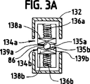
図3aは図3のインターロツク装置のA−A線での断面図である。
図4は超音波套管針組立体の組立分解図である。
図5は伝達部品と係合している図4の超音波套管針組立体のインターロツク装置の線図である。
図6は該伝達部品から係合が外れた図5のインターロツク装置の線図である。
図7は引き込められた位置にある組織負荷センサーを有する図5の超音波套管針組立体の線図である。
図8は伸ばされた位置での組織負荷センサーを有する図5の超音波套管針組立体の線図である。
図8aは図7のインターロツク装置の1部分の拡大図である。
好ましい実施例の詳細な説明
本発明は種々の形の実施例が可能であるが、図面で示され以下で説明される現在の好ましい実施例は、本開示が本発明の典型的例と考えるべきであり、本発明を図解された特定の実施例に限定しようと意図してないと言う理解を持って示すものである。
今図1を参照すると、外科用システム10の現在の好ましい実施例が図解されている。該外科用システム10は一般的に発振器30、ハンドピース組立体50,音響的又は伝達部組立体80,及びインターロツク装置又はブレーキ機構130を備えている。該発振器30はケーブル32を通して該発振器30の制御システムにより決定される選択された振幅、周波数、及び位相で電気信号を送る。更に説明される様に、該信号は該音響的組立体80の1つ以上のピエゾ電気素子を膨張及び収縮させ、それにより該電気的エネルギーを機械的運動に変換する。該機械的運動は超音波エネルギーの縦波となるが、該波は選択された周波数と振幅で該音響的組立体80を振動させる音響的定在波となり該音響的組立体80を通して伝播する。該超音波エネルギーを組織(tissue)に移すために該音響的組立体80の遠位の端部にある端末作働体(end effector)88が患者の組織に接触して置かれる。該音響的組立体80の該端末作働体88と接触した該組織の細胞は該端末作働体88と一緒に運動しそして振動する。
該端末作働体88が該組織と連結すると、該組織内の内部細胞摩擦の結果として熱的エネルギー又は熱が発生する。該熱はたんぱく質の水素結合を破壊するに充分であり、高構造たんぱく質(highly structured protein)(すなわち、コラーゲン及び筋肉たんぱく質)を変性させる{すなわち、より組織度の低いものにする(become less organized)}。たんぱく質が変性されると、該凝塊が100度Cより低くなった時接着性の凝塊が形成され細い血管を閉じ凝固させる。この効果が長くなると太い血管の深い凝固となる。
該組織への該超音波エネルギーの移送により機械的な引き裂き、切断、キャビテーション細胞破壊、そして乳化を含む他の効果が起こる。得られる凝固の度合のみでなく切断の量も該端末作働体の振動振幅、ユーザーの印加する圧力の量、そして該端末作働体88のシャープさと共に変化する。該外科用システム10の音響的組立体80の該端末作働体88は該システム10の振動エネルギーを該端末作働体88と接触する組織上に焦点を合わせようとしており、熱的及び機械的エネルギーの送り出しを強めたり局所化する。
図1に図解するように、該発振器30は該発振器30に必要な制御システム、電力スイッチ34,そしてトリガー機構36を備えている。該電力スイッチ34は該発振器30への電力を制御し、そして該トリガー機構36により賦活された時該発振器30はエネルギーを供給して該外科用システム10の該音響的組立体80を予め決められた周波数で駆動しそして該端末作働体88を予め決められた振動振幅レベルで駆動する。該発振器30は該音響的組立体80を該音響的組立体80の適当な何れの共振周波数で駆動又は励振しても良い。
該発振器30がトリガー機構36を介して賦活されると、該ブレーキ機構又はインターロツク装置130が下記説明の様に印加されるか、又は該トリガー機構36が賦活を止める迄電気的エネルギーが該発振器30により該音響的組立体80の変換器組立体82に連続的に印加される。該発振器30の制御システム内の位相同期ループ(phase locked loop)は該音響的組立体80からのフィードバックを監視する。該位相同期ループは該発振器30により送られる該電気的エネルギーの周波数を該音響的組立体80の予め選択された調波周波数に整合するように調整する。加えて、該音響的組立体80の該端末作働体88での実質的に一定な振動振幅を達成するために該制御システム内の第2のフィードバックループが該音響的組立体80に供給される電流を予め選択された一定レベルに保持する。該音響的組立体80に供給される該電気信号により該遠位の端部は、例えば、約20kHz乃至1100kHzの範囲で、そしてより好ましくは約54kHz乃至56kHzの範囲で、最も好ましくは約55.5kHzで縦振動する。該端末作働体88での音響的振動の振幅は、例えば、該発振器30により該音響的組立体80の変換器組立体82に印加される電気信号の振幅を制御することにより制御しても良い。
上記に述べたように、電気的エネルギーが該音響的組立体80に連続的に供給されるように、該発振器30のトリガー機構36がユーザーに該発振器30を賦活出来るようにしている。1つの実施例では、該トリガー機構36は好ましくは足踏み賦活スイッチを有しており、該スイッチはケーブル又はコードにより該発振器30に取り外し可能に接続されるか又は取り付けられていても良い。もう1つの実施例では、該発振器30がユーザーにより賦活されるように手動スイッチが該ハンドピース組立体50に組合わされていても良い。
又該発振器30は電気外科ユニット内又は従来型電気コンセントへ挿入するための電力線38を有している。該発振器30はバッテリーの様な直流(DC)電源により電力を与えられても良いことも考慮されている。該発振器30はエチコンエンドウ−サージェリー社(Ethicon Endo-surgery,Inc.)から入手可能のモデル番号ジェノー1(Model No.GENO1)の様な適当な如何なる発振器であっても良い。
なお図1を参照すると、該ハンドピース組立体50は手術者を該音響的組立体80の振動から遮断するよう適合された多数部品のハウジング又は外側ケーシング52を有している。該ハウジング52が好ましくは円筒型で従来の仕方でユーザーに保持されるよう適合されているのが良いが、ユーザーが握ることが出来るような適当な如何なる形状と寸法であっても良い。多数部品のハウジング52が図解されているが、該ハウジング52は1つの又はユニット型の部品を有しても良い。
該ハンドピース組立体50のハウジング52は好ましくはウルテム(Ultem▲R▼)の様な耐久性のあるプラスチックで作られるのが良い。又該ハウジング52を他のプラスチック{即ち、高耐衝撃性の(high impact)ポリスチレン又はポリプロピレン}を含む種々の材料で作っても良いことも考慮されている。適当なハンドピース組立体50はエチコンエンドウ−サージェリー社(Ethicon Endo-Surgery,Inc.)から入手可能なモデル番号エイチピー050(Model No.HP050)である。
図1に図解されている様に、全体としては該ハンドピース組立体50は近位の端部54、遠位の端部56、そして中央に配置されその中を縦方向に伸びている軸方向の開口部又は空洞58を有している。ハンドピース組立体50の該遠位の端部56は該外科用システム10の発振器組立体80が貫いて伸びられるように形状を有する開口部60を有し、ハンドピース組立体50の該近位の端部54はケーブル32により該発振器30に接続されている。該音響的組立体80の変換器組立体82を冷却するために該ハンドピース組立体50内に空気が導入されるように該ケーブル32はダクト又は換気口62を有しても良い。
なお図1を参照すると、全体としては該音響的組立体80は変換器スタック(stack)又は組立体82と伝達部品を備えている。該伝達部品は設置用素子84、伝達ロッド又は導波管86、そして端末作働体又はアップリケーター(applicator)88を備えている。該変換器組立体82,設置用素子84,伝達ロッド86、及び該端末作働体88は各部品の長さがシステム波長の半分の整数倍(nλ/2)になるように音響的に共振されているのが良いが、ここで該システム波長λは該音響的組立体80の予め選択された又は運転する縦振動周波数fの波長である。又該音響的組立体80は音響的素子の適当な如何なる配置と組み合わされても良いことも考慮されている。例えば、該音響的組立体80は変換器組立体と端末作働体を含んでも良い(即ち、該音響的組立体80は設置用素子と伝達ロッドなしで構成されても良い)。
該音響的組立体80の変換器組立体82は該発振器30からの電気信号を該端末作働体88の超音波周波数での縦振動運動となる機械的エネルギーに変換する。該音響的組立体80がエネルギーを与えられた時、該音響的組立体80を通して振動運動の定在波が発生する。該音響的組立体80に沿ってのどの点でも該振動運動の振幅は音響的組立体80に沿っての該振動運動が測定される位置に依って決まる。該振動運動定在波の最小即ちゼロっと交叉することは一般的に節と引用され(即ち、軸方向運動が通常最小で半径方向運動が通常小さい)、そして該定在波の絶対値の最大或いはピークは一般的に腹と引用される。腹とその最も近い節の間の距離は4分の1波長(λ/4)である。
図1に示すように、”ランジュバン振動子(Langevin stack)”として知られる該音響的組立体80の変換器組立体82は一般的に変換部分90、第1共鳴体92、そして第2共鳴体94を備えている。該変換器組立体82は好ましくは長さがシステム波長の半分の整数倍(nλ/2)であるのが良い。本発明は代わりに磁歪式、電磁式、又は静電式変換器を具備する変換器組立体を備えるよう構成されても良いことは理解されるべきである。
該第1の共鳴体92の遠位の端部は変換部分90の近位の端部に接続され、該第2の共鳴体94の近位の端部は変換部分90の遠位の端部に接続される。第1及び第2の共鳴体92及び94は好ましくはチタン、アルミニウム、鋼、又は他の適当な何らかの材料で作られるのが良い。第1及び第2の共鳴体92及び94は、変換部分90の厚さ、該共鳴体92と94で使用される材料の密度と弾性係数、そして該変換器組立体82の基本周波数を含む多くの変数により決定される長さを有する。第2の共鳴体94は超音波振動振幅を増幅するためにその近位の端部から遠位の端部へ向かい内側へテーパを付けても良い。
好ましくは該変換器組立体82の変換部分90は交互にある正電極96と負電極98のピエゾ電気部分を具備しており、ピエゾ電気素子100が該電極96と98の間に交互に存在する。該ピエゾ電気素子100は、例えば、ジルコン酸−チタン酸鉛(lead zirconate-titanate)、メタニオブ酸鉛(lead meta-niobate)、チタン酸鉛(lead titanate)、又はセラミックピエゾ電気結晶材料(ceramic piezoelectric crystal)の様な適当な何れかの材料から作られる。該正電極96、負電極98、そしてピエゾ電気素子100の各々は中心を通して伸びる孔を有しても良い。該正及び負電極96と98はそれぞれワイヤ102と104に電気的に接続されている。該ワイヤ102と104は電気信号を該発振器30から電極96と98へ伝送する。
図1に示すように、ピエゾ電気素子100はボルト106により第1及び第2の共鳴体92と94の間に圧縮して保持される。該ボルト106は好ましくは頭部、シャンク部、そしてねじ加工された遠位の端部を有するのが良い。該ボルト106は第1の共鳴体92の近位の端部から第1の共鳴体92、電極96と98、そしてピエゾ電気素子100の孔を通して挿入される。該ボルト106のねじ加工された遠位の端部は第2の共鳴体94の近位の端部内のねじ加工された孔にねじ込まれる。
該ピエゾ電気素子100は該発振器30から供給される電気信号に応答してエネルギーを与えられ該音響的組立体80内に音響的定在波を発生する。該電気信号は該材料内の大きな圧縮力となる繰り返された小変位の形で該ピエゾ電気素子100内に外乱を起こさせる。該繰り返された小変位は該ピエゾ電気素子100に電位傾度の軸線に沿って連続した仕方で膨張と収縮を起こさせ、超音波エネルギーの高周波縦波を発生する。該超音波エネルギーは該音響的組立体80を通して該端末作働体88に伝達される。
該音響的組立体80の設置用素子84は近位の端部、遠位の端部を有し、そしてシステム波長の半分の整数倍に実質的に等しい長さを有する。該設置用素子84の近位の端部は好ましくは腹に近い所でのめねじ結合により該第2の共鳴体94の遠位の端部と軸方向に整合され連結されているのが良い。(この開示の目的ためには、”近くに”と言う用語は”丁度そこに”又は”近くに近接して”と定義されている。)又該設置用素子84は適当な何らかの手段で第2の共鳴体94に取り付けられても良く、そして該第2の共鳴体94と設置用素子84は1つの又はユニット化した部品として形成されても良いことが考慮されている。
該設置用素子84は節の近くで該ハンドピース組立体50の該ハウジング52に連結又は設置されている。該設置用素子84はその周辺部の周りに配置された構成用リング(integral ring)108を備えていても良い。該構成用リング108は好ましくは該設置用素子84を該ハウジング58に結合するために該ハンドピース組立体50のハウジング52内に形成された円環状の溝110内に配置される。埋め合わせ(stand-offs)により取り付けられた1対のシリコンオーリング(silicone O-ring)の様なコンプライアントな部材又は材料112が該ハウジング52の円環状溝110と該設置用素子84の構成用リング108の間に置かれて、超音波振動を該設置用素子84から該ハウジング52へ伝達されるのを減少させるか又は防止する。
設置用素子84は複数の、好ましくは4本のピン114で予め決められた軸方向位置に固着される。該ピン114は該設置用素子84の外周部の周りに相互に90度離れるようにして縦方向に配置される。該ピン114は該ハンドピース組立体50の該ハウジング52に結合され該設置用素子84の構成用リング108内のノッチを通して配置される。該ピン114は好ましくはステンレス鋼で作るのが良い。
該設置用素子84は好ましくは該音響的組立体80を通して該端末作働体88の遠位の端部に伝達される超音波振動振幅を増幅するよう構成されるのが良い。1つの好ましい実施例では、該設置用素子は中味の詰まったテーパ付きのホーンを備えている。超音波エネルギーは該設置用素子84を通して伝達されるので、該設置用素子84を通して伝達される音響波の速度は増幅される。該設置用素子84は段付きホーン、円錐形ホーン、指数ホーン、又は類似のものの様な適当な如何なる形状でも良いことは考慮されている。
該設置用素子84の遠位の端部は該伝達ロッド86の近位の端部に連結されている。該伝達ロッド86が、例えば、めねじ結合の様な適当な何らかの手段によって該設置用素子84に取り付けらることは考慮されている。該設置用素子84は好ましくは腹の近くで該伝達ロッドに連結されるのが良い。
該伝達ロッド86は、例えば、システム波長の半分の整数倍(nλ/2)に実質的に等しい長さを有するのが良い。該伝達ロッド86は好ましくは、チタン合金(即ち、Ti-6A1-4V)又はアルミニウム合金の様な超音波エネルギーを効率的に伝播する材料で作られた中味の詰まった心材のシャフトから作られるのが良い。該伝達ロッド86が適当な何れの材料ででも作られて良いことを考慮してある。又、該伝達ロッド86は該伝達ロッド86を通して該端末作働体88に伝達される機械的振動を従来技術で公知の様に増幅しても良い。
図1に図解されている様に、該伝達ロッド86は複数の節に位置付けされた安定化用シリコンリング(silicone rings)又はコンプライアントな支持部116を備えている。該シリコンリングは望ましくない振動に制動をかけそして該超音波振動を取り外し可能なシース120から遮断して該端末作働体88の遠位の端部への長手方向の超音波エネルギーの最高効率での流れを保証してくれる。
該取り外し可能なシース120は該ハンドピース組立体50の遠位の端部56と連結されている。該シース120は一般的にはアダプター又はノーズコーン(nose cone)122及び長いチューブ状部材124を備えている。該長いチューブ状部材124は該アダプター122から伸びておりそしてそれを通して長手方向に伸びる開口部を有している。該シース120は該ハウジング52の遠位の端部上にねじ止めされても或いはスナップ式に止められても良い。該音響的組立体80の伝達ロッド86は該チューブ状部材124の該開口部を通して伸びておりそして、該シリコンリング116は該伝達ロッド86を該チューブ状部材124から遮断している。
該シース120のアダプター122は好ましくはウルテム(Ultem▲R▼)で作られそして該チューブ状部材124はステンレス鋼から作られるのが良い。代わりに該伝達ロッド86が外部接触からそれを分離するために該伝達ロッド86を取り囲むポリマー材料を有しても良い。
該伝達ロッド86の遠位の端部は、好ましくは腹で又は腹の近くでめねじ結合により該端末作働体88の近位の端部と連結されている。該端末作働体88が溶接接合や類似の接合の様な適当な何れの手段によっても該伝達ロッド86に取り付けられて良いことが考慮されている。該端末作働体88は該伝達ロッド86から取り外し可能であっても良いが、該端末作働体88と該伝達ロッド86は1つのユニットとして形成されても良いことも又考慮されている。
該端末作働体88はその近位の範囲88aより小さい断面面積を有する遠位の範囲88bを有しており、それにより振動振幅のステップアップ用接合部(step-up junction)を形成している。該ステップアップ接合部は従来技術で公知の速度変圧器として作用し、該端末作働体88の近位の範囲88aから遠位の範囲88bへ伝達される超音波振動の大きさを増大する。
該端末作働体88は好ましくはシステム波長の半分の整数倍に実質的に等しい長さを有するのが良い(nλ/2)。該遠位の端部の最大の縦たわみを発生するために該端末作働体88は腹の近くに配置される。該変換器組立体82がエネルギーを与えられると、該端末作働体88の遠位の端部は、予め決められた振動周波数で、例えばピークピーク値で約0.01乃至0.5ミリメートルの範囲で、好ましくは約0.03乃至0.1ミリメートルの範囲で、最も好ましくは約0.09ミリメートルで縦運動するよう構成されている。
該端末作働体88は好ましくは、チタン合金(即ち、Ti-6A1-4V)又はアルミニウム合金の様な超音波エネルギーを伝播する材料で作られた中味の詰まった心材のシャフトで作るのが良い。該端末作働体88が適当な何らかの材料で作られても良いことは考慮されている。エネルギーの供給と望ましい組織効果(tissue effect)を改良するために該端末作働体88が表面処理を施されることも考慮されている。例えば、組織内の凝固を促進するために、該端末作働体88は、マイクロフイニッシュ、塗装、メッキ、エッチング、グリットブラスト仕上げ、粗面化、又は刻み付け(scored)を行っても良い。加えて、該端末作働体88はそのエネルギー伝達特性を向上するためにシャープにしたり形状を持たせても良い。例えば、該端末作働体88はブレード形や、フック形や、又はボール形にしても良い。
今図2,3、及び3aを参照すると、該外科用システム10のインターロツク装置130の線図が図解されている。該インターロツク装置130は好ましくは該伝達部材86の近囲の端部の近くに位置付けされるのが良い。該インターロツク装置130が該音響的組立体80に沿って適当な何れの場所に位置付けされても良いことは考慮されている。例えばそして制限無しに、該インターロツク装置130は該変換器組立体82,該設置用素子84、又は該端末作働体88と接触するよう位置付けされても良い。該音響的組立体に沿って複数のインターロツク装置が位置付けされても良いことが承認されている。
該外科用システム10のインターロツク装置130は当業者に承認される様に該ハンドピース組立体又は該取り外し可能なシースにに組み合わされたり、結合されたりしても良い。図2,3及び3aに示す様に、該インターロツク装置130はハウジング132とブレーキ用部材134a及び134bを備えている。該ブレーキ用部材134a及び134bは好ましくは該伝達ロッド86の相対する側の上に設置されるのが良い。該インターロツク装置130が適当な如何なる数のブレーキ用部材134a及び134b(即ち1個乃至6個)を有しても良くそして該伝達ロッド86と係合するような適当な如何なる配置で設置されても良いことは承認されている。
該インターロツク装置130は手動又は自動で動かされる。例えば、ユーザーが超音波エネルギーに制動をかけたり、減少させたりそして/又は停止させるために該ブレーキ用部材134a及び134bを押し下げると該インターロツク装置130は該音響的組立体に向かって押されても良い。代わりに、該端末作働体88が患者の望まれた組織(即ち、患者の腹壁又は心臓の内壁)を貫入した時に該超音波エネルギーに制動をかけたり、減少させたりそして/又は停止させるために該インターロツク装置が賦活されても良い。
該端末作働体88の運動を何時停止するかを決定するために検出装置が使用されても良い。該検出機構は該インターロツク装置130が該端末作働体88に供給される超音波エネルギーに制動をかけるよう賦活される点である何時該端末作働体が該組織を貫入したかを検出するため使用される。該検出機構は該端末作働体88が何時適切な組織貫入を果たしそして何時該ブレーキ用部材134a及び134bの賦活に機械的にトリガーをかけるかを検出する機械的負荷変化センサーを備えている。該インターロツク装置130は適切な貫入に対応するインピーダンス(impedance)レベルを検出した又は検知した時に賦活されても良いことは考慮されている。例えば、米国特許第5、449、370号は該端末作働体の負荷又はインピーダンスの変化を検出するフイードバック機構を開示している。該インターロツク装置130はユーザーが該発振器、該ハンドピース組立体、又は該取り外し可能なシース内に結合されたボタン又はスイッチを押した時にトリガーを掛けられても良く或いは該インターロツク装置は例えば機械的トリガーの様な適当な手段により該組立体を駆動するよう賦活されても良いことは承認されている。
好ましくは該インターロツク装置130のブレーキ用部材134a及び134bは弾性のある部材136a及び136bとブレーキパッド138a及び138bとを備えても良い。好ましくはブレーキパッド138a及び138bは長方形の形状であるのが良い。該ブレーキパッド138a及び138bが如何なる形状と寸法であっても良いことも又考慮されている。該ブレーキパッド138a及び138bは1つのパッドを有しても或いは複数のパッドを有しても良い。
該ブレーキパッド138a及び138bは高い動作温度を有しそして該伝達ロッド86を引っ掻いたり或いは削ったりしないように作られている。該ブレーキパッド138a及び138bがポリテトラフルオロエチレン(polytetra fluoroethylene){ピーテーエフイー/テーエフイー(PTFE/TFE)}又はフルオロエチレンプロピレン(fluorinated ethylene-propylene){エフイーピー(FEP)}で作られても良い。該ブレーキパッド138a及び138bが従来技術で公知の適当な如何なる材料であっても良いことは承認されている。
好ましくは該各ブレーキパッド138a及び138bは該伝達ロッド86の周辺部と合致する前面135a及び135bをそれぞれ備えているのが良い。図3aに示す様に該前面135a及び135bは各々該伝達ロッド86と係合するために凹面又は溝139a及び139bをそれぞれ有している。該ブレーキ用部材134a及び134bの前面が望ましい如何なる形状を有しても良くそして実質的に平坦でも良いことは考慮されている。又該ブレーキパッド138a及び138bが該ブレーキパッドを保持する裏板により担われていても良いことも考慮されている。
弾性のある部材136a及び136bが該ブレーキパッド138a及び138bの後ろに取り付けられている。該弾性のある部材136a及び136bは該ブレーキパッド138a及び138bを該伝達ロッド86の方に偏倚させている。好ましくは、該弾性部材136a及び136bはばねを含んでいる。又該弾性部材136a及び136bが例えばソレノイド、空気圧ピストン、等の様な該ブレーキパッド138a及び138bを偏倚させる適当な何らかの機構を具備しても良いことも考慮されている。
該インターロツク装置130のブレーキパッド138a及び138bは該伝達ロッド及び/又は端末作働体の超音波振動に制動をかけたり、減少させたり又は停止させるために適当な点又は場所で該音響的組立体の周辺部と係合するよう適合されることも可能である。好ましくは該ブレーキパッド138a及び138bは腹の付近で該音響的組立体に当てられるのが良い。
使用時は、該インターロツク装置130のブレーキ用部材134a及び134bは図2に示す様に引き込まれた或いは係合解除された位置にある。この位置で、該ブレーキパッド138a及び138bは該伝達ロッド86から予め決められた距離離れて保持されている。該伝達ロッドの超音波振動に制動をかけたり停止させたりしたい時、該ブレーキ用部材134a及び134bは図3に示す様に該伝達ロッドに向かって押される。該ブレーキ用部材134a及び134bのブレーキパッド138a及び138bが該伝達ロッドに向かって押されると、該超音波伝達ロッドのインピーダンスは充分に増加されるので該発振器30はもはや該伝達ロッドの共振周波数に拘束することが出来なくなり適当な駆動信号を発生出来なくなる。結果として該伝達ロッドの運動は停止しそして該発振器は連続音を報ずる。
今図4を参照すると、典型的な超音波套管針組立体200が図解されている。該超音波套管針組立体200は多くの点で上記の外科用システム10と一致するように構成出来ることは理解される。従って、本開示の目的のために該套管針組立体200は異なるように述べる所を除くと、上記の様に該外科用システム10と一致するよう構成されている。該超音波套管針組立体200は該套管針組立体200がチューブ状套管針カニューレと一緒に使用出来る超音波閉塞具を備えていることで図1に図解する外科用システム10とは異なっている。引例によりここで組み合わされている米国特許第5、449、370号は套管針組立体のチューブ状カニューレを次ぎに導入するため体腔壁の超音波貫入を可能にするよう構成された超音波閉塞具を含む超音波套管針組立体を開示している。
図4に示す様に、該套管針組立体200は閉塞具180として構成された音響的組立体を含んでいるが、該閉塞具は構造と機能に於いて多くの点で外科用システム10の前記音響的組立体と対応している。一般的には外科用システム10の部品に対応する該套管針組立体200の部品は100と200のシリースで同様な番号で呼称されている。
該套管針組立体200の閉塞具180は前記説明の変換器組立体82と一致して構成され中に位置する変換器組立体182を有するハウジング152を備えている。該閉塞具180の取り扱いを容易にするため該套管針組立体のハウジング152と結合されたハンドグリップ153が提供されるのが好ましい。該套管針組立体の套管針カニューレ159の近位のハウジング157との協同的に解除可能なかつロック式の係合用に1対の手動操作可能なロック用クリップ155が該ハンドグリップ153の上部部分に備えられるのが好ましい。チューブ状カニューレ161を備える該套管針カニューレ159は該組立体の閉塞具180と解除可能なロック式係合状態で位置付けされ、該閉塞具180は概ね伸縮関係を有して該チューブ状カニューレ161内に同軸に配置されている。
前述の様に、該閉塞具180は一般的には外科用システム10の前記説明の音響的組立体80と一致した構成である。この目的のために、該閉塞具180は遠位の端末作働体部分188を有する概ね細長い伝達ロッド又は導波管186を備えている。該端末作働体188は該導波管の残りの長さ部分とユニットにする(即ち、1部品にする)ことが出来るか又は該端末作働体は例えばねじ結合又は同様な結合による様に細長い導波管に接合された別部品とすることも出来る。導波管186は適当な設置用要素184により該変換器組立体182に動作的に連結されるが、そこでは超音波エネルギーは該変換器組立体から該導波管を通って伝達される。
該好ましい形では、細長い導波管186は該導波管の周りに概ね同軸に位置付けされた概ねチューブ状でシースの様な振動しないハウジング内に収容される。図解された実施例では、この好ましい方式は中に複数のコンプライアントな分離用支持部216を担う複数のチューブ状シース部材220の形で提供されるが、該支持部は該チューブ状シース部材を導波管186が担う該超音波エネルギーから望ましく遮断する機能を有している。かくして該支持部216は前記説明の外科用システム10の音響的組立体80の支持部116の性質の機能を果たしている。チューブ状部材220はスナップ式嵌合、ねじ結合、又は他の適当な手段で組立されても良い。
該套管針組立体の図解された実施例では、該閉塞具180の遠位の端部部分の外側のシースの様なハウジングの組立は協力関係で連結部材213と嵌合する1対のシース部分221を設けることにより容易になる。該連結部材213は該シース部分221を協力的に受けるスリットスリーブを備えており、一方最も遠位にあるシース部分221が必要により該連結部材213から取り外し可能にしてある。
該閉塞具180の外側のチューブ状ハウジングは更に該最も遠位にあるシース部分221と作動的に連結されたインターフエース本体217を備えており、該インターフエース本体217を内部に位置する導波管186の振動エネルギーから遮断するために再び分離支持部216が備えられるのが好ましい。
使用時は、該組立体の超音波閉塞具180は該套管針カニューレ159のチューブ状カニューレ161の内部に伸縮可能に位置付けされる。ロック用クリップ155が套管針カニューレ159の近位のハウジング157と係合しているのが良く、かくして器具全体を1ユニットとしてハンドグリップ153により容易に取り扱えるようにされている。該閉塞具を該カニューレ内に位置させ、端末作働体188を含む該閉塞具の自由端部はチューブ状カニューレ161の遠位の端部から突出している。
今図5、6、7、8及び8aを参照すると、図4の套管針組立体200と共に使用するよう構成されたインターロツク装置300の線図が図解されている。該インターロツク装置300は当業者には承認される様に適当な何れの場所ででも閉塞具又はチューブ状套管針カニューレと連結又は組み合わせられて良い。好ましくは該インターロツク装置300はハウジング310、導波管を含む閉塞具316、ブレーキ用部材320a及び320b、作動可能状態化(arming)カラー(collar)330、そしてリセットボタン340を備えるのが良い。
ブレーキ用部材320a及び320bは好ましくは導波管316の相対する側に設置されるのが良い。該ブレーキ用部材320a及び320bは導波管316の近位の端部の近くに位置付けされるのが好ましい。該ブレーキ用部材320a及び320bが該音響的組立体に沿う適当な如何なる位置に位置付けられても良いと考慮されている。該インターロツク装置300は適当な如何なる数(即ち、1個乃至6個)のブレーキ用部材320a及び320bを有していても良く、そして該伝達ロッド186と係合する適当な如何なる配置で設置されても良いと承認されている。
該ブレーキ用部材320a及び320bは好ましくは弾性のある部材322a及び322bとブレーキパッド324a及び324bを備えるのが良い。該ブレーキパッド324a及び324bは好ましくは長方形の形状であるのが良い。又該ブレーキパッド324a及び324bがどんな形状と寸法であっても良いことは考慮されている。該ブレーキパッド324a及び324bは好ましくは高い動作温度を有しておりそして該閉塞具の導波管316を引っ掻いたり又は削ったりしないように作られるのが良い。該ブレーキパッド324aおよび324bはポリテトラフルオロエチレン(polytetrafluoroethylene){ピーテーエフイー/テーエフイー(PTFE/TFE)}又はフルオロエチレンプロピレン(fluorinated ethylene-propylene){エフイーピー(FEP)}で作られるのが良い。該ブレーキパッド324a及び324bが従来技術の適当な如何なる材料で作られても良いことは承認されている。
該ブレーキパッド324a及び324bは好ましくは該導波管316の周辺部と合致する前面を備えるのが良い。好ましくは、該前面は該導波管316を受け入れるように凹面又は溝を有するのが良い。該ブレーキ用部材320a及び320bの前面が望ましい如何なる形状を有しても良くそして実質的に平坦でであっても良いと考慮されている。
弾性のある部材322a及び322bが該ブレーキ用部材320a及び320bの背後に取り付けられている。該弾性のある部材322a及び322bは該ブレーキ用部材320a及び320bを該導波管316の方へ偏倚させる。好ましくは、該弾性のある部材322a及び322bは各々ばねを備えるのが良い。該弾性のある部材322a及び322bが例えばソレノイドや、空気圧ピストン等の様に該ブレーキ用部材320a及び320bを偏倚させる適当な何らかの機構を含んでも良いことも考慮されている。
該インターロツク装置130の作動可能状態化カラー330は好ましくはばね負荷を掛けられているのが良い。該ブレーキ用部材320a及び320bが該導波管316に向かって押された時、図5に示すように該カラー330は引き込められた位置にある。一旦該ブレーキ用部材320及び320bが該導波管316から離されると、該カラー330は好ましくは図6に示す様に該ブレーキ用部材320a及び320bの間に配置されるのが良い。該作動可能状態化カラー330は該ブレーキ用部材320a及び320bを該導波管316から離して保持する。該作動可能状態化カラー330は、例えば、ばねの様な弾性のある部材339により偏倚されている。
該ブレーキ用部材320a及び320bは又カム面328a及び328bを備えても良い。該カム面328a及び328bは好ましくは該近位の端部から遠位の端部へ内側へ角度を持っているのが良い。図5でリセットボタン340が矢印350aの方向に動かされると、該リセットボタンは該カム面328a及び328bと係合しそして図6に示すように該ブレーキ用部材320a及び320bを加圧して該導波管316から離間させる。
該インターロツク装置300の該ブレーキ用部材320a及び320bは該超音波振動に制動をかけたり或いは停止させるために該音響的組立体に沿う適当な点又は場所で該導波管186の周辺部と係合するように適合されている。該ブレーキ用部材320a及び320bは好ましくは腹の近くで当てられるのが良い。
最初に、該ブレーキ用部材320a及び320bは該導波管316と係合され、そして該リセットボタン340は図5に図解されるように該ブレーキ用部材320a及び320bから後方へ位置付けされている。次いで図6に示す様に該ブレーキ用部材320a及び320bを該導波管316から押し離すために該リセットボタン340を前へ押すことにより該インターロツク装置300が作動可能状態化される。この位置で該ブレーキ用部材320a及び230bは該作動可能状態化カラー330により該導波管316から離れた予め決められた距離に保持される。該作動可能状態化カラー330は該ばね339により該ブレーキ用部材320a及び320bの間の空間内へ偏倚されている。次いで外科医は該発振器を賦活し該音響的組立体にエネルギーを与える。
該超音波閉塞具の遠位の端部が貫入すべき体腔壁と接触して位置するよう該套管針組立体が次に位置付けされる。この位置付けの前又は後の何れかに、該超音波システムはエネルギーを与えられ、それにより該変換器組立体から該閉塞具の遠位の端部への超音波エネルギーの伝達を行う。該導波管を通して伝達されている該超音波エネルギーが該壁の細胞構造に作用すると該ハンドグリップ153を経由した適当な圧力をかけることにより(図4参照)、該閉塞具の遠位の端部の該体腔壁への貫入をさせる状態は実施可能となる。
図7に示す様に、該外科医は該套管針組立体を患者の組織に向かって加圧を開始する。該組織負荷センサー350が引き込むと、中央ポストは下から該ブレーキ用部材320a及び320bの間の空間内へ移動する。該閉塞具が該組織内へ進むにつれ、該組織負荷センサー350は引き込むことを続け該中央ポストが該作動可能状態化カラー330に向かって押すようにさせてそして図7に示すように該カラーを該ブレーキ用部材320a及び320bの間から外へ出す。好ましくは、該中央ポスト351は該作動可能状態化カラー330より小さい直径を有するのが良く、該ブレーキ用部材は僅かに内側へ動き該作動可能状態化カラー330の再係合を防止するが、しかし該閉塞具の導波管316と係合する程充分には動かない方が良い。次いで、該超音波套管針組立体は押されて該組織を通り過ぎそして腔内へ入るが、恰もそれは腹膜に於ける様である。
該閉塞具が該腔に入ると、該組織負荷センサー350への抵抗は実質的に無くなりそして該組織負荷センサー350は、例えば、ばね(図示せず)により前進する。該組織負荷センサー350が前進すると該中央ポスト351は該ブレーキの間の範囲から出てそして該ブレーキが該導波管316と接触出来るようにする。該ブレーキ用部材320a及び320bが該閉塞具に向かって押されると、該ブレーキ用部材320a及び320bは好ましくは該超音波導波管のインピーダンスを充分に増加させるのが良く、該発振器は該音響的組立体の共振周波数に固定されていることがもはや出来ず適当な駆動信号を発生する。結果として該導波管の運動は停止し、そして該発振器は連続音を報ずる。
該超音波閉塞具により貫入用開口部を形成後、該超音波システムの動作を終了出来る。後方に、かつ、最初に形成された貫入用開口部が該套管針カニューレのチューブ状カニューレの次ぎの導入を行えるように充分拡大されるよう、該閉塞具は遠位の方へ進められる。次いで該カニューレは該広げられ拡大された開口部を通して進められるが、該超音波閉塞具は該チューブ状カニューレを導入する前か後に該拡大された貫入用開口部を通して取り除かれる。ロック用クリップの操作は該閉塞具が該套管針カニューレから取り外されそして完全に取り除かれ、そして所要の内視鏡による外科過程が実行されるのを可能にする。
上記から、本発明の新しい概念の真の精神と範囲から離れること無く多くの変型や変更を実現出来ことが着想される。本開示は本発明の典型的なものとして意図されており特定の図解した実施例に本発明を限定しようとするものではないことは理解されるべきである。本開示は該請求項の範囲に入る様な全ての変型を付属する請求項によりカバーするよう意図されている。Background of the Invention
TECHNICAL FIELD OF THE INVENTION
The present invention generally relates to an ultrasonic device, and more particularly to an ultrasonic interlock device or a brake mechanism capable of braking ultrasonic vibration of a transmission component.
Technical background of the invention
Endoscopic minimally invasive endoscopic surgical processes are becoming increasingly widespread in view of reducing patient trauma and its cost effectiveness. For this process, a trocar assembly is typically used for effective penetration into the patient's body cavity wall. A typical trocar assembly includes a tissue-piercing obturator having an outer tubular cannula and an inner puncturing tip. In use, the trocar assembly is positioned such that the obturator is advanced at the puncture tip to form an opening in the body cavity wall, after which the cannula is inserted through the opening. The obturator is then removed from within the cannula, after which the cannula provides an entrance for insertion of surgical instruments and other devices associated with the surgical process being performed.
Many trocar assemblies have a retractable or removable shield that can cover the puncture tip of the obturator, thus covering the tissue piercing portion of the assembly. To do. When the trocar assembly is positioned to puncture a patient's body cavity, the shield can be retracted to expose the puncture tip to pierce the body cavity wall. Once the body cavity is pierced, the shield again covers the puncture tip of the obturator. For example, in abdominal surgery, the shield covers the puncture tip of the obturator when it reaches the peritoneal cavity.
The use of ultrasonic surgical instruments is also becoming increasingly popular due to the unique performance characteristics of the device. Depending on the specific instrument configuration and operating parameters, the device can provide tissue cutting and hemostasis at substantially the same time, which also desirably minimizes patient trauma.
U.S. Pat. No. 5,449,370, which is hereby incorporated by reference, is a superstructure configured to enable ultrasonic penetration of a body cavity wall for subsequent introduction of a tubular cannula of a trocar assembly. An ultrasonic trocar assembly with a sonic obturator is disclosed. The obturator of the trocar assembly has an insensitive or rounded tip to minimize patient trauma associated with penetration of the body cavity. As the obturator penetrates the patient's tissue, a feedback mechanism closes or reduces the ultrasonic energy supplied to the obturator.
The present invention is directed to an interlock device or brake mechanism that mechanically attenuates ultrasonic energy supplied to a transmission component.
Summary of the present invention
An ultrasonic interlocking device embodying the principles of the present invention results from mechanical damping of transmission component vibrations. The interlock device engages the periphery of the transmission component to brake, stop or reduce the vibration of the transmission component. When the interlock device engages the transmission component, a force is applied to the transmission component to prevent the ultrasonic energy from being transmitted through the transmission component.
The interlock device can also engage the transmission component to prevent inadvertent supply of ultrasonic energy. The interlock device may be used on any suitable ultrasonic device or ultrasonic surgical device such as, for example, an ultrasonic scalpel and an ultrasonic trocar.
The ultrasonic surgical device of the present invention includes a transducer assembly adapted to vibrate at an ultrasonic frequency in response to electrical energy. A transmission component is adapted to receive ultrasonic vibrations from the transducer assembly and to transmit the ultrasonic vibrations from the first end to the second end. A braking device is configured to apply a force to the outer surface of the transmission component to apply a brake while ultrasonic vibrations are transmitted from the first end of the transmission rod to the second end of the transmission rod. Has been.
The method according to the present invention includes the step of providing an ultrasonic trocar obturator having an ultrasonic waveguide with a terminal actuator at a distal end thereof, and the trocar obturator within the trocar cannula. A positioning process, a positioning process of the trocar obturator in contact with the body cavity wall, and a process of creating an intrusion opening by vibrating the end effector with ultrasonic waves. The method also includes advancing the ultrasonic obturator into the penetrating opening, detecting when the penetration is complete, and applying a force to the obturator to brake ultrasonic vibrations of the end effector. Applying a brake member and advancing the trocar cannula into the penetration opening.
Other features and advantages of the present invention will be readily apparent from the following detailed description, the accompanying drawings, and the appended claims.
[Brief description of the drawings]
FIG. 1 is a partial view with a section in part of an embodiment of the surgical system of the present invention.
FIG. 2 is a diagram of the interlocking device of the surgical system of FIG. 1 in the retracted position.
FIG. 3 is a diagram of the interlock device of FIG. 2 in the engaged position.
FIG. 3a is a cross-sectional view taken along line AA of the interlock device of FIG.
FIG. 4 is an exploded view of the ultrasonic trocar assembly.
FIG. 5 is a diagram of the interlock device of the ultrasonic trocar assembly of FIG. 4 engaged with a transmission component.
FIG. 6 is a diagram of the interlock device of FIG. 5 disengaged from the transmission component.
7 is a diagram of the ultrasonic trocar assembly of FIG. 5 with the tissue load sensor in the retracted position.
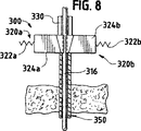
FIG. 8 is a diagram of the ultrasonic trocar assembly of FIG. 5 with the tissue load sensor in the extended position.
FIG. 8a is an enlarged view of a portion of the interlock device of FIG.
Detailed Description of the Preferred Embodiment
While the invention is susceptible to various forms of embodiments, the presently preferred embodiments shown in the drawings and described below are to be considered as exemplary of the invention, and the present invention is illustrated by way of illustration. It is shown with the understanding that it is not intended to be limited to the specific embodiments described.
Referring now to FIG. 1, a presently preferred embodiment of a
When the
Transfer of the ultrasonic energy to the tissue produces other effects including mechanical tearing, cutting, cavitation cell disruption, and emulsification. The amount of cutting as well as the degree of coagulation obtained varies with the vibration amplitude of the end effector, the amount of pressure applied by the user and the sharpness of the
As illustrated in FIG. 1, the
When the
As described above, the
The
Still referring to FIG. 1, the handpiece assembly 50 includes a multi-part housing or
The
As illustrated in FIG. 1, generally, the handpiece assembly 50 includes a
Still referring to FIG. 1, as a whole, the
The
As shown in FIG. 1, the
The distal end of the
Preferably, the
As shown in FIG. 1, the
The
The mounting
The
The
The mounting
The distal end of the mounting
The
As illustrated in FIG. 1, the
The
The
The distal end of the
The
The
The
Referring now to FIGS. 2, 3 and 3a, a diagram of the
The
The
A detection device may be used to determine when to stop the movement of the
Preferably, the
The
Preferably, each
In use, the
Referring now to FIG. 4, a typical
As shown in FIG. 4, the
The
As described above, the
In the preferred form, the
In the illustrated embodiment of the trocar assembly, the assembly of the housing, such as the outer sheath of the distal end portion of the
The tubular housing outside the
In use, the
Referring now to FIGS. 5, 6, 7, 8 and 8a, a diagram of an
The
The
The
The
The
The
Initially, the
The trocar assembly is then positioned such that the distal end of the ultrasonic obturator is positioned in contact with the body cavity wall to be penetrated. Either before or after this positioning, the ultrasound system is energized, thereby effecting transmission of ultrasound energy from the transducer assembly to the distal end of the obturator. When the ultrasonic energy transmitted through the waveguide acts on the cellular structure of the wall, by applying appropriate pressure via the handgrip 153 (see FIG. 4), the distal end of the obturator The state in which the part is penetrated into the body cavity wall can be performed.
As shown in FIG. 7, the surgeon begins to press the trocar assembly toward the patient's tissue. When the
As the obturator enters the cavity, the resistance to the
After the penetration opening is formed by the ultrasonic obturator, the operation of the ultrasonic system can be terminated. The obturator is advanced distally so that the penetrating opening formed initially is sufficiently enlarged to allow subsequent introduction of the tubular cannula of the trocar cannula. The cannula is then advanced through the widened and enlarged opening, while the ultrasonic obturator is removed through the enlarged penetrating opening before or after introducing the tubular cannula. Operation of the locking clip allows the obturator to be removed from the trocar cannula and completely removed and the required endoscopic surgical process to be performed.
From the above, it is envisaged that many variations and modifications can be realized without departing from the true spirit and scope of the new concept of the present invention. It is to be understood that this disclosure is intended to be exemplary of the invention and is not intended to limit the invention to the specific illustrated embodiments. This disclosure is intended to cover all such modifications as fall within the scope of the claims.
Claims (10)
電気的エネルギーに応答して超音波周波数で振動するよう適合された変換器組立体と、
第1の端部と第2の端部とを有する設置用素子とを具備しており、該設置用素子は該変換器組立体から超音波振動を受けるようそして該超音波振動を該設置用素子の該第1の端部から該第2の端部へ伝達するよう適合されており、該設置用素子の該第1の端部は該変換器組立体と連結されており、
該装置は又第1の端部と第2の端部とを有する伝達ロッドを具備しており、該伝達ロッドは該設置用素子から該超音波振動を受けるようそして該超音波振動を該伝達ロッドの該第1の端部から該第2の端部へ伝達するよう適合されており、
該装置は更に係合を解除される位置と該伝達ロッドの該第1の端部から該伝達ロッドの該第2の端部へ該超音波振動が伝達されるのを減少させるために該伝達ロッドの周辺部に力を印加する係合される位置との間を動くよう構成された移動可能なブレーキと、
第1の端部と第2の端部とを有する端末作働体とを具備しており、該端末作働体は該ブレーキが賦活される迄該伝達ロッドから該超音波振動を受けるようそして該超音波振動を該端末作働体の該第1の端部から該第2の端部へ伝達するよう適合されており、該端末作働体の該第2の端部は腹の近くに配置されておりそして該端末作働体の該第1の端部は該伝達ロッドの該第2の端部に連結されていることを特徴とする超音波式装置。In ultrasonic equipment,
A transducer assembly adapted to vibrate at an ultrasonic frequency in response to electrical energy;
An installation element having a first end and a second end, the installation element receiving ultrasonic vibrations from the transducer assembly and applying the ultrasonic vibrations to the installation Adapted to transmit from the first end of an element to the second end, wherein the first end of the mounting element is coupled to the transducer assembly;
The apparatus also includes a transmission rod having a first end and a second end, the transmission rod receiving the ultrasonic vibration from the installation element and transmitting the ultrasonic vibration. Adapted to transmit from the first end of the rod to the second end;
The apparatus further includes the transmission to reduce disengagement and transmission of the ultrasonic vibrations from the first end of the transmission rod to the second end of the transmission rod. A movable brake configured to move between engaged positions applying a force to the periphery of the rod;
A terminal actuating body having a first end and a second end, the terminal actuating body receiving the ultrasonic vibration from the transmission rod until the brake is activated and Adapted to transmit sonic vibrations from the first end of the end effector to the second end, the second end of the end effector being located near the belly The ultrasonic device is characterized in that the first end of the terminal actuating body is connected to the second end of the transmission rod.
電気的エネルギーに応答して超音波周波数で振動するよう適合された変換器組立体と、A transducer assembly adapted to vibrate at an ultrasonic frequency in response to electrical energy;
第1の端部と第2の端部とを有する伝達部品とを具備しており、該伝達部品は該変換器組立体から超音波振動を受けるようそして該超音波振動を該第1の端部から該第2の端部へ伝達するよう適合されており、そしてA transmission component having a first end and a second end, the transmission component receiving ultrasonic vibration from the transducer assembly and transmitting the ultrasonic vibration to the first end. Adapted to transmit from the part to the second end; and
該装置は又該伝達ロッドの該第1の端部から該伝達ロッドの該第2の端部へ該超音波振動が伝達されるのに制動をかけるために該伝達部品の外面に力を印加するよう構成されたブレーキ装置を具備しており、前記ブレーキ装置は超音波振動が前記伝達部品を通して伝達されるような係合を解除された状態と前記ブレーキ装置が前記伝達部品を通しての超音波振動の伝達に制動をかける係合された状態との間で選択的に動作可能であることを特徴とする超音波式外科用装置。The device also applies a force to the outer surface of the transmission component to brake the ultrasonic vibrations transmitted from the first end of the transmission rod to the second end of the transmission rod. The brake device is configured to be disengaged such that ultrasonic vibration is transmitted through the transmission component, and the brake device is ultrasonic vibration through the transmission component. An ultrasonic surgical device characterized in that it is selectively operable between an engaged state that brakes transmission of the device.
ハンドルを有するカニューレ及び該カニューレハンドルから伸びるカニューレチューブと、A cannula having a handle and a cannula tube extending from the cannula handle;
該カニューレチューブを通して挿入されるよう適合された閉塞具とを具備しており、該閉塞具は超音波変換器と、伝達ロッドと、そして端末作働体を備えており、該超音波変換器は選択された周波数で振動するよう適合されており、An obturator adapted to be inserted through the cannula tube, the obturator comprising an ultrasonic transducer, a transmission rod, and a terminal actuator, the ultrasonic transducer being selected Adapted to vibrate at a specified frequency,
該伝達ロッドは第1の端部と第2の端部とを備えており、該伝達ロッドの該第1の端部は該超音波変換器と連結されており、該第2の端部は該端末作働体と連結されており、そしてThe transmission rod has a first end and a second end, the first end of the transmission rod is connected to the ultrasonic transducer, and the second end is Connected to the terminal actuator, and
該組立体は又該伝達ロッドと係合するよう適合されたブレーキ装置を具備しており、前記ブレーキ装置は引き込められた位置から、それを通しての超音波振動の伝達に制動をかけるためにブレーキパッドが前記伝達ロッドと係合する係合された位置まで移動可能な少なくとも1つのブレーキパッドを有することを特徴とする套管針組立体。The assembly also includes a braking device adapted to engage the transmission rod, the braking device from the retracted position to brake the transmission of ultrasonic vibrations therethrough. A trocar assembly having at least one brake pad movable to an engaged position where the pad engages the transmission rod.
第1の端部と第2の端部とを有する伝達部品を具備しており、該伝達部品は超音波振動を受けるようそして該超音波振動を第1の端部から第2の端部へ伝達するよう適合されており、そしてA transmission component having a first end and a second end, the transmission component receiving ultrasonic vibrations and transmitting the ultrasonic vibrations from the first end to the second end. Adapted to communicate, and
該器具は又該伝達ロッドの該第1の端部から該伝達ロッドの該第2の端部へ該超音波振動が伝達されるのを減少するために該伝達部品に力を印加するよう構成されたブレーキ装置を具備しており、The instrument is also configured to apply a force to the transmission component to reduce transmission of the ultrasonic vibrations from the first end of the transmission rod to the second end of the transmission rod. Equipped with a brake device,
前記ブレーキ装置は超音波振動が前記伝達部品を通して伝達可能となる係合が解除された状態と、それを通しての超音波振動の伝達に制動をかけるため前記ブレーキ要素が前記伝達部品と係合するような係合された状態との間で動作可能な少なくとも1つの移動可能なブレーキ要素を有することを特徴とする超音波式外科用器具。The brake device is in a disengaged state in which ultrasonic vibration can be transmitted through the transmission component, and the brake element is engaged with the transmission component in order to brake transmission of ultrasonic vibration through the brake device An ultrasonic surgical instrument having at least one movable brake element operable between a fully engaged state.
Applications Claiming Priority (3)
| Application Number | Priority Date | Filing Date | Title |
|---|---|---|---|
| US808,638 | 1997-02-28 | ||
| US08/808,638 US5968060A (en) | 1997-02-28 | 1997-02-28 | Ultrasonic interlock and method of using the same |
| PCT/US1998/003052 WO1998037821A1 (en) | 1997-02-28 | 1998-02-19 | Ultrasonic interlock |
Publications (3)
| Publication Number | Publication Date |
|---|---|
| JP2001527461A JP2001527461A (en) | 2001-12-25 |
| JP2001527461A5 JP2001527461A5 (en) | 2005-10-06 |
| JP3911033B2 true JP3911033B2 (en) | 2007-05-09 |
Family
ID=25199331
Family Applications (1)
| Application Number | Title | Priority Date | Filing Date |
|---|---|---|---|
| JP53771298A Expired - Fee Related JP3911033B2 (en) | 1997-02-28 | 1998-02-19 | Ultrasonic interlocking device |
Country Status (8)
| Country | Link |
|---|---|
| US (1) | US5968060A (en) |
| EP (1) | EP0914067B1 (en) |
| JP (1) | JP3911033B2 (en) |
| AU (1) | AU728847B2 (en) |
| CA (1) | CA2252823C (en) |
| DE (1) | DE69818393T2 (en) |
| ES (1) | ES2209119T3 (en) |
| WO (1) | WO1998037821A1 (en) |
Families Citing this family (188)
| Publication number | Priority date | Publication date | Assignee | Title |
|---|---|---|---|---|
| US8229549B2 (en) | 2004-07-09 | 2012-07-24 | Tyco Healthcare Group Lp | Surgical imaging device |
| ATE551955T1 (en) | 2001-04-20 | 2012-04-15 | Tyco Healthcare | SURGICAL DEVICE HAVING BIPOLAR OR ULTRASONIC FEATURES |
| ATE398413T1 (en) * | 2001-04-20 | 2008-07-15 | Power Med Interventions Inc | IMAGING DEVICE |
| US11229472B2 (en) | 2001-06-12 | 2022-01-25 | Cilag Gmbh International | Modular battery powered handheld surgical instrument with multiple magnetic position sensors |
| EP2428172B1 (en) | 2001-09-24 | 2013-07-24 | Applied Medical Resources Corporation | Bladeless obturator |
| DE60336303D1 (en) * | 2002-01-30 | 2011-04-21 | Tyco Healthcare | SURGICAL IMAGING DEVICE |
| DE60337002D1 (en) | 2002-05-16 | 2011-06-16 | Applied Med Resources | OBTURATOR WITH CONE TIP |
| US7776027B2 (en) | 2002-07-11 | 2010-08-17 | Misonix, Incorporated | Medical handpiece with automatic power switching means |
| CN1684626A (en) | 2002-09-30 | 2005-10-19 | 能量医学介入公司 | Self-contained sterilizable surgical system |
| EP2545861B1 (en) | 2003-10-03 | 2014-02-12 | Applied Medical Resources Corporation | Bladeless optical obturator |
| US8951275B2 (en) * | 2003-11-20 | 2015-02-10 | Children's Medical Center Corporation | Trocar for use during endoscopy |
| US8182501B2 (en) | 2004-02-27 | 2012-05-22 | Ethicon Endo-Surgery, Inc. | Ultrasonic surgical shears and method for sealing a blood vessel using same |
| JP4249064B2 (en) * | 2004-03-10 | 2009-04-02 | オリンパス株式会社 | Endoscope |
| CA2572192A1 (en) | 2004-06-29 | 2006-01-12 | Applied Medical Resources Corporation | Insufflating optical surgical instrument |
| PL1802245T3 (en) | 2004-10-08 | 2017-01-31 | Ethicon Endosurgery Llc | Ultrasonic surgical instrument |
| US20070191713A1 (en) | 2005-10-14 | 2007-08-16 | Eichmann Stephen E | Ultrasonic device for cutting and coagulating |
| US7621930B2 (en) | 2006-01-20 | 2009-11-24 | Ethicon Endo-Surgery, Inc. | Ultrasound medical instrument having a medical ultrasonic blade |
| US8517977B2 (en) | 2006-10-06 | 2013-08-27 | Applied Medical Resources Corporation | Visual insufflation port |
| US8057498B2 (en) | 2007-11-30 | 2011-11-15 | Ethicon Endo-Surgery, Inc. | Ultrasonic surgical instrument blades |
| US8142461B2 (en) * | 2007-03-22 | 2012-03-27 | Ethicon Endo-Surgery, Inc. | Surgical instruments |
| US20080234709A1 (en) | 2007-03-22 | 2008-09-25 | Houser Kevin L | Ultrasonic surgical instrument and cartilage and bone shaping blades therefor |
| US8911460B2 (en) | 2007-03-22 | 2014-12-16 | Ethicon Endo-Surgery, Inc. | Ultrasonic surgical instruments |
| US8226675B2 (en) | 2007-03-22 | 2012-07-24 | Ethicon Endo-Surgery, Inc. | Surgical instruments |
| US8882791B2 (en) | 2007-07-27 | 2014-11-11 | Ethicon Endo-Surgery, Inc. | Ultrasonic surgical instruments |
| US8808319B2 (en) | 2007-07-27 | 2014-08-19 | Ethicon Endo-Surgery, Inc. | Surgical instruments |
| US8257377B2 (en) | 2007-07-27 | 2012-09-04 | Ethicon Endo-Surgery, Inc. | Multiple end effectors ultrasonic surgical instruments |
| US8348967B2 (en) | 2007-07-27 | 2013-01-08 | Ethicon Endo-Surgery, Inc. | Ultrasonic surgical instruments |
| US8523889B2 (en) | 2007-07-27 | 2013-09-03 | Ethicon Endo-Surgery, Inc. | Ultrasonic end effectors with increased active length |
| US8430898B2 (en) | 2007-07-31 | 2013-04-30 | Ethicon Endo-Surgery, Inc. | Ultrasonic surgical instruments |
| US8252012B2 (en) | 2007-07-31 | 2012-08-28 | Ethicon Endo-Surgery, Inc. | Ultrasonic surgical instrument with modulator |
| US8512365B2 (en) | 2007-07-31 | 2013-08-20 | Ethicon Endo-Surgery, Inc. | Surgical instruments |
| US9044261B2 (en) | 2007-07-31 | 2015-06-02 | Ethicon Endo-Surgery, Inc. | Temperature controlled ultrasonic surgical instruments |
| USD594983S1 (en) | 2007-10-05 | 2009-06-23 | Ethicon Endo-Surgery, Inc. | Handle assembly for surgical instrument |
| JP2010540186A (en) | 2007-10-05 | 2010-12-24 | エシコン・エンド−サージェリィ・インコーポレイテッド | Ergonomic surgical instrument |
| US7901423B2 (en) | 2007-11-30 | 2011-03-08 | Ethicon Endo-Surgery, Inc. | Folded ultrasonic end effectors with increased active length |
| US10010339B2 (en) | 2007-11-30 | 2018-07-03 | Ethicon Llc | Ultrasonic surgical blades |
| AU2009206222B2 (en) | 2008-01-25 | 2014-05-29 | Applied Medical Resources Corporation | Insufflating surgical access system |
| US8058771B2 (en) | 2008-08-06 | 2011-11-15 | Ethicon Endo-Surgery, Inc. | Ultrasonic device for cutting and coagulating with stepped output |
| US9089360B2 (en) | 2008-08-06 | 2015-07-28 | Ethicon Endo-Surgery, Inc. | Devices and techniques for cutting and coagulating tissue |
| US20100057118A1 (en) * | 2008-09-03 | 2010-03-04 | Dietz Timothy G | Ultrasonic surgical blade |
| EP3799811B1 (en) | 2008-09-29 | 2022-03-30 | Applied Medical Resources Corporation | First-entry trocar system |
| US20100145258A1 (en) * | 2008-12-08 | 2010-06-10 | David Hertweck | Systems and methods for eliminating post-excitation vibration in ophthalmic surgical handpieces |
| US9700339B2 (en) | 2009-05-20 | 2017-07-11 | Ethicon Endo-Surgery, Inc. | Coupling arrangements and methods for attaching tools to ultrasonic surgical instruments |
| US8344596B2 (en) | 2009-06-24 | 2013-01-01 | Ethicon Endo-Surgery, Inc. | Transducer arrangements for ultrasonic surgical instruments |
| US8461744B2 (en) | 2009-07-15 | 2013-06-11 | Ethicon Endo-Surgery, Inc. | Rotating transducer mount for ultrasonic surgical instruments |
| US8663220B2 (en) | 2009-07-15 | 2014-03-04 | Ethicon Endo-Surgery, Inc. | Ultrasonic surgical instruments |
| US9017326B2 (en) | 2009-07-15 | 2015-04-28 | Ethicon Endo-Surgery, Inc. | Impedance monitoring apparatus, system, and method for ultrasonic surgical instruments |
| US10172669B2 (en) | 2009-10-09 | 2019-01-08 | Ethicon Llc | Surgical instrument comprising an energy trigger lockout |
| US9168054B2 (en) | 2009-10-09 | 2015-10-27 | Ethicon Endo-Surgery, Inc. | Surgical generator for ultrasonic and electrosurgical devices |
| USRE47996E1 (en) | 2009-10-09 | 2020-05-19 | Ethicon Llc | Surgical generator for ultrasonic and electrosurgical devices |
| US8956349B2 (en) | 2009-10-09 | 2015-02-17 | Ethicon Endo-Surgery, Inc. | Surgical generator for ultrasonic and electrosurgical devices |
| US11090104B2 (en) | 2009-10-09 | 2021-08-17 | Cilag Gmbh International | Surgical generator for ultrasonic and electrosurgical devices |
| US10441345B2 (en) | 2009-10-09 | 2019-10-15 | Ethicon Llc | Surgical generator for ultrasonic and electrosurgical devices |
| US8579928B2 (en) | 2010-02-11 | 2013-11-12 | Ethicon Endo-Surgery, Inc. | Outer sheath and blade arrangements for ultrasonic surgical instruments |
| US8323302B2 (en) | 2010-02-11 | 2012-12-04 | Ethicon Endo-Surgery, Inc. | Methods of using ultrasonically powered surgical instruments with rotatable cutting implements |
| US9259234B2 (en) | 2010-02-11 | 2016-02-16 | Ethicon Endo-Surgery, Llc | Ultrasonic surgical instruments with rotatable blade and hollow sheath arrangements |
| US8382782B2 (en) | 2010-02-11 | 2013-02-26 | Ethicon Endo-Surgery, Inc. | Ultrasonic surgical instruments with partially rotating blade and fixed pad arrangement |
| US8951272B2 (en) | 2010-02-11 | 2015-02-10 | Ethicon Endo-Surgery, Inc. | Seal arrangements for ultrasonically powered surgical instruments |
| US8486096B2 (en) | 2010-02-11 | 2013-07-16 | Ethicon Endo-Surgery, Inc. | Dual purpose surgical instrument for cutting and coagulating tissue |
| US8531064B2 (en) | 2010-02-11 | 2013-09-10 | Ethicon Endo-Surgery, Inc. | Ultrasonically powered surgical instruments with rotating cutting implement |
| US8469981B2 (en) | 2010-02-11 | 2013-06-25 | Ethicon Endo-Surgery, Inc. | Rotatable cutting implement arrangements for ultrasonic surgical instruments |
| US8961547B2 (en) | 2010-02-11 | 2015-02-24 | Ethicon Endo-Surgery, Inc. | Ultrasonic surgical instruments with moving cutting implement |
| US8419759B2 (en) | 2010-02-11 | 2013-04-16 | Ethicon Endo-Surgery, Inc. | Ultrasonic surgical instrument with comb-like tissue trimming device |
| GB2480498A (en) | 2010-05-21 | 2011-11-23 | Ethicon Endo Surgery Inc | Medical device comprising RF circuitry |
| US8795327B2 (en) | 2010-07-22 | 2014-08-05 | Ethicon Endo-Surgery, Inc. | Electrosurgical instrument with separate closure and cutting members |
| US9192431B2 (en) | 2010-07-23 | 2015-11-24 | Ethicon Endo-Surgery, Inc. | Electrosurgical cutting and sealing instrument |
| US8979890B2 (en) | 2010-10-01 | 2015-03-17 | Ethicon Endo-Surgery, Inc. | Surgical instrument with jaw member |
| US8888809B2 (en) | 2010-10-01 | 2014-11-18 | Ethicon Endo-Surgery, Inc. | Surgical instrument with jaw member |
| US9113943B2 (en) | 2011-03-30 | 2015-08-25 | Covidien Lp | Ultrasonic surgical instruments |
| US9114181B2 (en) | 2011-03-30 | 2015-08-25 | Covidien Lp | Process of cooling surgical device battery before or during high temperature sterilization |
| US8968293B2 (en) | 2011-04-12 | 2015-03-03 | Covidien Lp | Systems and methods for calibrating power measurements in an electrosurgical generator |
| WO2012151276A2 (en) | 2011-05-02 | 2012-11-08 | Applied Medical Resources Corporation | Low-profile surgical universal access port |
| US9980741B2 (en) | 2011-06-13 | 2018-05-29 | P Tech, Llc | Methods and systems for controlling an ultrasonic handpiece based on tuning signals |
| US9259265B2 (en) | 2011-07-22 | 2016-02-16 | Ethicon Endo-Surgery, Llc | Surgical instruments for tensioning tissue |
| USD700967S1 (en) | 2011-08-23 | 2014-03-11 | Covidien Ag | Handle for portable surgical device |
| US20130085419A1 (en) | 2011-09-29 | 2013-04-04 | Tyco Healthcare Group Lp | Transducer/Waveguide Engagement Mechanisms for Ultrasonic Surgical Instruments |
| US9333025B2 (en) | 2011-10-24 | 2016-05-10 | Ethicon Endo-Surgery, Llc | Battery initialization clip |
| USD687549S1 (en) | 2011-10-24 | 2013-08-06 | Ethicon Endo-Surgery, Inc. | Surgical instrument |
| EP2811932B1 (en) | 2012-02-10 | 2019-06-26 | Ethicon LLC | Robotically controlled surgical instrument |
| US9439668B2 (en) | 2012-04-09 | 2016-09-13 | Ethicon Endo-Surgery, Llc | Switch arrangements for ultrasonic surgical instruments |
| US9241731B2 (en) | 2012-04-09 | 2016-01-26 | Ethicon Endo-Surgery, Inc. | Rotatable electrical connection for ultrasonic surgical instruments |
| US9237921B2 (en) | 2012-04-09 | 2016-01-19 | Ethicon Endo-Surgery, Inc. | Devices and techniques for cutting and coagulating tissue |
| US9724118B2 (en) | 2012-04-09 | 2017-08-08 | Ethicon Endo-Surgery, Llc | Techniques for cutting and coagulating tissue for ultrasonic surgical instruments |
| US9226766B2 (en) | 2012-04-09 | 2016-01-05 | Ethicon Endo-Surgery, Inc. | Serial communication protocol for medical device |
| US10080563B2 (en) | 2012-06-01 | 2018-09-25 | Covidien Lp | Loading unit detection assembly and surgical device for use therewith |
| US20140005705A1 (en) | 2012-06-29 | 2014-01-02 | Ethicon Endo-Surgery, Inc. | Surgical instruments with articulating shafts |
| US9408622B2 (en) | 2012-06-29 | 2016-08-09 | Ethicon Endo-Surgery, Llc | Surgical instruments with articulating shafts |
| US9351754B2 (en) | 2012-06-29 | 2016-05-31 | Ethicon Endo-Surgery, Llc | Ultrasonic surgical instruments with distally positioned jaw assemblies |
| US20140005702A1 (en) | 2012-06-29 | 2014-01-02 | Ethicon Endo-Surgery, Inc. | Ultrasonic surgical instruments with distally positioned transducers |
| US9326788B2 (en) | 2012-06-29 | 2016-05-03 | Ethicon Endo-Surgery, Llc | Lockout mechanism for use with robotic electrosurgical device |
| US9820768B2 (en) | 2012-06-29 | 2017-11-21 | Ethicon Llc | Ultrasonic surgical instruments with control mechanisms |
| US9283045B2 (en) | 2012-06-29 | 2016-03-15 | Ethicon Endo-Surgery, Llc | Surgical instruments with fluid management system |
| US9226767B2 (en) | 2012-06-29 | 2016-01-05 | Ethicon Endo-Surgery, Inc. | Closed feedback control for electrosurgical device |
| US9393037B2 (en) | 2012-06-29 | 2016-07-19 | Ethicon Endo-Surgery, Llc | Surgical instruments with articulating shafts |
| US9198714B2 (en) | 2012-06-29 | 2015-12-01 | Ethicon Endo-Surgery, Inc. | Haptic feedback devices for surgical robot |
| BR112015007010B1 (en) | 2012-09-28 | 2022-05-31 | Ethicon Endo-Surgery, Inc | end actuator |
| US9241732B2 (en) | 2012-10-16 | 2016-01-26 | Covdien LP | Surgical instrument |
| US9095367B2 (en) | 2012-10-22 | 2015-08-04 | Ethicon Endo-Surgery, Inc. | Flexible harmonic waveguides/blades for surgical instruments |
| US10201365B2 (en) | 2012-10-22 | 2019-02-12 | Ethicon Llc | Surgeon feedback sensing and display methods |
| US20140135804A1 (en) | 2012-11-15 | 2014-05-15 | Ethicon Endo-Surgery, Inc. | Ultrasonic and electrosurgical devices |
| US10226273B2 (en) | 2013-03-14 | 2019-03-12 | Ethicon Llc | Mechanical fasteners for use with surgical energy devices |
| US9241728B2 (en) | 2013-03-15 | 2016-01-26 | Ethicon Endo-Surgery, Inc. | Surgical instrument with multiple clamping mechanisms |
| US9814514B2 (en) | 2013-09-13 | 2017-11-14 | Ethicon Llc | Electrosurgical (RF) medical instruments for cutting and coagulating tissue |
| US9265926B2 (en) | 2013-11-08 | 2016-02-23 | Ethicon Endo-Surgery, Llc | Electrosurgical devices |
| GB2521229A (en) | 2013-12-16 | 2015-06-17 | Ethicon Endo Surgery Inc | Medical device |
| GB2521228A (en) | 2013-12-16 | 2015-06-17 | Ethicon Endo Surgery Inc | Medical device |
| US9795436B2 (en) | 2014-01-07 | 2017-10-24 | Ethicon Llc | Harvesting energy from a surgical generator |
| US9554854B2 (en) | 2014-03-18 | 2017-01-31 | Ethicon Endo-Surgery, Llc | Detecting short circuits in electrosurgical medical devices |
| US10463421B2 (en) | 2014-03-27 | 2019-11-05 | Ethicon Llc | Two stage trigger, clamp and cut bipolar vessel sealer |
| US10092310B2 (en) | 2014-03-27 | 2018-10-09 | Ethicon Llc | Electrosurgical devices |
| US9737355B2 (en) | 2014-03-31 | 2017-08-22 | Ethicon Llc | Controlling impedance rise in electrosurgical medical devices |
| GB2525033A (en) | 2014-04-10 | 2015-10-14 | Asm Assembly Systems Switzerland Gmbh | Screen printing apparatus and method |
| US9913680B2 (en) | 2014-04-15 | 2018-03-13 | Ethicon Llc | Software algorithms for electrosurgical instruments |
| US9700333B2 (en) | 2014-06-30 | 2017-07-11 | Ethicon Llc | Surgical instrument with variable tissue compression |
| US10285724B2 (en) | 2014-07-31 | 2019-05-14 | Ethicon Llc | Actuation mechanisms and load adjustment assemblies for surgical instruments |
| WO2016069998A1 (en) | 2014-10-30 | 2016-05-06 | Intuitive Surgical Operations, Inc. | System and method for articulated arm stabilization |
| CN105662545B (en) * | 2014-11-16 | 2019-04-26 | 广州迪克医疗器械有限公司 | Radial seal assembly, end seal and puncture outfit |
| US10639092B2 (en) | 2014-12-08 | 2020-05-05 | Ethicon Llc | Electrode configurations for surgical instruments |
| US10159524B2 (en) | 2014-12-22 | 2018-12-25 | Ethicon Llc | High power battery powered RF amplifier topology |
| US10245095B2 (en) | 2015-02-06 | 2019-04-02 | Ethicon Llc | Electrosurgical instrument with rotation and articulation mechanisms |
| US10342602B2 (en) | 2015-03-17 | 2019-07-09 | Ethicon Llc | Managing tissue treatment |
| US10321950B2 (en) | 2015-03-17 | 2019-06-18 | Ethicon Llc | Managing tissue treatment |
| US10595929B2 (en) | 2015-03-24 | 2020-03-24 | Ethicon Llc | Surgical instruments with firing system overload protection mechanisms |
| US10314638B2 (en) | 2015-04-07 | 2019-06-11 | Ethicon Llc | Articulating radio frequency (RF) tissue seal with articulating state sensing |
| US10034684B2 (en) | 2015-06-15 | 2018-07-31 | Ethicon Llc | Apparatus and method for dissecting and coagulating tissue |
| US11020140B2 (en) | 2015-06-17 | 2021-06-01 | Cilag Gmbh International | Ultrasonic surgical blade for use with ultrasonic surgical instruments |
| US10357303B2 (en) | 2015-06-30 | 2019-07-23 | Ethicon Llc | Translatable outer tube for sealing using shielded lap chole dissector |
| US11141213B2 (en) | 2015-06-30 | 2021-10-12 | Cilag Gmbh International | Surgical instrument with user adaptable techniques |
| US11051873B2 (en) | 2015-06-30 | 2021-07-06 | Cilag Gmbh International | Surgical system with user adaptable techniques employing multiple energy modalities based on tissue parameters |
| US10034704B2 (en) | 2015-06-30 | 2018-07-31 | Ethicon Llc | Surgical instrument with user adaptable algorithms |
| US11129669B2 (en) | 2015-06-30 | 2021-09-28 | Cilag Gmbh International | Surgical system with user adaptable techniques based on tissue type |
| US10898256B2 (en) | 2015-06-30 | 2021-01-26 | Ethicon Llc | Surgical system with user adaptable techniques based on tissue impedance |
| US10154852B2 (en) | 2015-07-01 | 2018-12-18 | Ethicon Llc | Ultrasonic surgical blade with improved cutting and coagulation features |
| US10687884B2 (en) | 2015-09-30 | 2020-06-23 | Ethicon Llc | Circuits for supplying isolated direct current (DC) voltage to surgical instruments |
| US10959771B2 (en) | 2015-10-16 | 2021-03-30 | Ethicon Llc | Suction and irrigation sealing grasper |
| US10595930B2 (en) | 2015-10-16 | 2020-03-24 | Ethicon Llc | Electrode wiping surgical device |
| US10179022B2 (en) | 2015-12-30 | 2019-01-15 | Ethicon Llc | Jaw position impedance limiter for electrosurgical instrument |
| US10959806B2 (en) | 2015-12-30 | 2021-03-30 | Ethicon Llc | Energized medical device with reusable handle |
| US10575892B2 (en) | 2015-12-31 | 2020-03-03 | Ethicon Llc | Adapter for electrical surgical instruments |
| US10709469B2 (en) | 2016-01-15 | 2020-07-14 | Ethicon Llc | Modular battery powered handheld surgical instrument with energy conservation techniques |
| US11229471B2 (en) | 2016-01-15 | 2022-01-25 | Cilag Gmbh International | Modular battery powered handheld surgical instrument with selective application of energy based on tissue characterization |
| US11129670B2 (en) | 2016-01-15 | 2021-09-28 | Cilag Gmbh International | Modular battery powered handheld surgical instrument with selective application of energy based on button displacement, intensity, or local tissue characterization |
| US10716615B2 (en) | 2016-01-15 | 2020-07-21 | Ethicon Llc | Modular battery powered handheld surgical instrument with curved end effectors having asymmetric engagement between jaw and blade |
| US10555769B2 (en) | 2016-02-22 | 2020-02-11 | Ethicon Llc | Flexible circuits for electrosurgical instrument |
| US10646269B2 (en) | 2016-04-29 | 2020-05-12 | Ethicon Llc | Non-linear jaw gap for electrosurgical instruments |
| US10702329B2 (en) | 2016-04-29 | 2020-07-07 | Ethicon Llc | Jaw structure with distal post for electrosurgical instruments |
| US10987156B2 (en) | 2016-04-29 | 2021-04-27 | Ethicon Llc | Electrosurgical instrument with electrically conductive gap setting member and electrically insulative tissue engaging members |
| US10856934B2 (en) | 2016-04-29 | 2020-12-08 | Ethicon Llc | Electrosurgical instrument with electrically conductive gap setting and tissue engaging members |
| US10485607B2 (en) | 2016-04-29 | 2019-11-26 | Ethicon Llc | Jaw structure with distal closure for electrosurgical instruments |
| US10456193B2 (en) | 2016-05-03 | 2019-10-29 | Ethicon Llc | Medical device with a bilateral jaw configuration for nerve stimulation |
| US10245064B2 (en) | 2016-07-12 | 2019-04-02 | Ethicon Llc | Ultrasonic surgical instrument with piezoelectric central lumen transducer |
| US10893883B2 (en) | 2016-07-13 | 2021-01-19 | Ethicon Llc | Ultrasonic assembly for use with ultrasonic surgical instruments |
| US10842522B2 (en) | 2016-07-15 | 2020-11-24 | Ethicon Llc | Ultrasonic surgical instruments having offset blades |
| US10376305B2 (en) | 2016-08-05 | 2019-08-13 | Ethicon Llc | Methods and systems for advanced harmonic energy |
| US10285723B2 (en) | 2016-08-09 | 2019-05-14 | Ethicon Llc | Ultrasonic surgical blade with improved heel portion |
| USD847990S1 (en) | 2016-08-16 | 2019-05-07 | Ethicon Llc | Surgical instrument |
| US10952759B2 (en) | 2016-08-25 | 2021-03-23 | Ethicon Llc | Tissue loading of a surgical instrument |
| US10828056B2 (en) | 2016-08-25 | 2020-11-10 | Ethicon Llc | Ultrasonic transducer to waveguide acoustic coupling, connections, and configurations |
| US10751117B2 (en) | 2016-09-23 | 2020-08-25 | Ethicon Llc | Electrosurgical instrument with fluid diverter |
| JP2019536539A (en) * | 2016-11-14 | 2019-12-19 | レ ソルシオン メディカール サウンドバイト インコーポレイテッド | Connector for mechanical waveguide |
| US10603064B2 (en) | 2016-11-28 | 2020-03-31 | Ethicon Llc | Ultrasonic transducer |
| US11266430B2 (en) | 2016-11-29 | 2022-03-08 | Cilag Gmbh International | End effector control and calibration |
| US11033325B2 (en) | 2017-02-16 | 2021-06-15 | Cilag Gmbh International | Electrosurgical instrument with telescoping suction port and debris cleaner |
| US10799284B2 (en) | 2017-03-15 | 2020-10-13 | Ethicon Llc | Electrosurgical instrument with textured jaws |
| US11497546B2 (en) | 2017-03-31 | 2022-11-15 | Cilag Gmbh International | Area ratios of patterned coatings on RF electrodes to reduce sticking |
| US10603117B2 (en) | 2017-06-28 | 2020-03-31 | Ethicon Llc | Articulation state detection mechanisms |
| US10820920B2 (en) | 2017-07-05 | 2020-11-03 | Ethicon Llc | Reusable ultrasonic medical devices and methods of their use |
| US11490951B2 (en) | 2017-09-29 | 2022-11-08 | Cilag Gmbh International | Saline contact with electrodes |
| US11484358B2 (en) | 2017-09-29 | 2022-11-01 | Cilag Gmbh International | Flexible electrosurgical instrument |
| US11033323B2 (en) | 2017-09-29 | 2021-06-15 | Cilag Gmbh International | Systems and methods for managing fluid and suction in electrosurgical systems |
| US11213316B2 (en) | 2018-03-09 | 2022-01-04 | The Children's Medical Center Corporation | Gasket with multi-leaflet valve for surgical port apparatus |
| US11786291B2 (en) | 2019-12-30 | 2023-10-17 | Cilag Gmbh International | Deflectable support of RF energy electrode with respect to opposing ultrasonic blade |
| US20210196359A1 (en) | 2019-12-30 | 2021-07-01 | Ethicon Llc | Electrosurgical instruments with electrodes having energy focusing features |
| US20210196363A1 (en) | 2019-12-30 | 2021-07-01 | Ethicon Llc | Electrosurgical instrument with electrodes operable in bipolar and monopolar modes |
| US11779387B2 (en) | 2019-12-30 | 2023-10-10 | Cilag Gmbh International | Clamp arm jaw to minimize tissue sticking and improve tissue control |
| US11684412B2 (en) | 2019-12-30 | 2023-06-27 | Cilag Gmbh International | Surgical instrument with rotatable and articulatable surgical end effector |
| US20210196344A1 (en) | 2019-12-30 | 2021-07-01 | Ethicon Llc | Surgical system communication pathways |
| US11696776B2 (en) | 2019-12-30 | 2023-07-11 | Cilag Gmbh International | Articulatable surgical instrument |
| US11944366B2 (en) | 2019-12-30 | 2024-04-02 | Cilag Gmbh International | Asymmetric segmented ultrasonic support pad for cooperative engagement with a movable RF electrode |
| US11812957B2 (en) | 2019-12-30 | 2023-11-14 | Cilag Gmbh International | Surgical instrument comprising a signal interference resolution system |
| US11950797B2 (en) | 2019-12-30 | 2024-04-09 | Cilag Gmbh International | Deflectable electrode with higher distal bias relative to proximal bias |
| US11779329B2 (en) | 2019-12-30 | 2023-10-10 | Cilag Gmbh International | Surgical instrument comprising a flex circuit including a sensor system |
| US11452525B2 (en) | 2019-12-30 | 2022-09-27 | Cilag Gmbh International | Surgical instrument comprising an adjustment system |
| US11937863B2 (en) | 2019-12-30 | 2024-03-26 | Cilag Gmbh International | Deflectable electrode with variable compression bias along the length of the deflectable electrode |
| US20210196349A1 (en) | 2019-12-30 | 2021-07-01 | Ethicon Llc | Electrosurgical instrument with flexible wiring assemblies |
| US11911063B2 (en) | 2019-12-30 | 2024-02-27 | Cilag Gmbh International | Techniques for detecting ultrasonic blade to electrode contact and reducing power to ultrasonic blade |
| US11660089B2 (en) | 2019-12-30 | 2023-05-30 | Cilag Gmbh International | Surgical instrument comprising a sensing system |
| US11957342B2 (en) | 2021-11-01 | 2024-04-16 | Cilag Gmbh International | Devices, systems, and methods for detecting tissue and foreign objects during a surgical operation |
Family Cites Families (107)
| Publication number | Priority date | Publication date | Assignee | Title |
|---|---|---|---|---|
| US30536A (en) * | 1860-10-30 | The graphic co | ||
| US2874470A (en) * | 1954-05-28 | 1959-02-24 | James R Richards | High frequency dental tool |
| US3075288A (en) * | 1954-12-24 | 1963-01-29 | Cavitron Ultrasonics Inc | Dental instrument |
| US3213537A (en) * | 1954-12-24 | 1965-10-26 | Cavitron Corp | Supply and control apparatus for vibratory cutting device |
| US2845072A (en) * | 1955-06-21 | 1958-07-29 | William A Shafer | Surgical knife |
| NL132749C (en) * | 1958-08-29 | 1900-01-01 | ||
| US3053124A (en) * | 1959-11-16 | 1962-09-11 | Cavitron Ultrasonics Inc | Ultrasonic welding |
| US3293456A (en) * | 1963-03-18 | 1966-12-20 | Branson Instr | Ultrasonic cleaning apparatus |
| US3433226A (en) * | 1965-07-21 | 1969-03-18 | Aeroprojects Inc | Vibratory catheterization apparatus and method of using |
| US3375583A (en) * | 1966-03-10 | 1968-04-02 | C & B Inc | Ultrasonic dental tool |
| US3368280A (en) * | 1966-03-23 | 1968-02-13 | C & B Inc | Dental tool |
| NL145136C (en) * | 1967-07-25 | 1900-01-01 | ||
| US3636943A (en) * | 1967-10-27 | 1972-01-25 | Ultrasonic Systems | Ultrasonic cauterization |
| US3657056A (en) * | 1967-12-11 | 1972-04-18 | Ultrasonic Systems | Ultrasonic suturing apparatus |
| GB1274671A (en) * | 1968-04-01 | 1972-05-17 | Sven Karl Lennart Goof | Ultrasonic dental apparatus |
| US3488851A (en) * | 1968-04-18 | 1970-01-13 | Zoltan Haydu | Ultrasonic devices |
| US3489930A (en) * | 1968-07-29 | 1970-01-13 | Branson Instr | Apparatus for controlling the power supplied to an ultrasonic transducer |
| SE329037B (en) * | 1969-02-20 | 1970-09-28 | Philips Nv | |
| US3589012A (en) * | 1969-06-30 | 1971-06-29 | C & B Corp | Tip for ultrasonic dental instrument |
| US3593425A (en) * | 1969-09-10 | 1971-07-20 | Hydrosonic Corp | Electric ultrasonic tooth-cleaning apparatus |
| US3654502A (en) * | 1970-06-24 | 1972-04-04 | Countronic Corp | Ultrasonic tool |
| US3703037A (en) * | 1970-06-25 | 1972-11-21 | Seymour Robinson | Ultrasonic dental hand-piece with detachable treatment tools |
| DE2032501A1 (en) | 1970-07-01 | 1972-01-05 | Kloz, Eduard; Kloz, Heinz; 7211 Hausen | Device for rendering harmless preferably bladder, uretheric and renal pelvic stones |
| CH541958A (en) * | 1970-11-03 | 1973-09-30 | Eduard Kloz & Heinz Kloz | Device for smashing bladder, ureter and renal pelvic stones using ultrasound |
| US3636947A (en) * | 1970-12-03 | 1972-01-25 | Ultrasonic Systems | Ultrasonic home dental instrument and method |
| US3654540A (en) * | 1971-01-15 | 1972-04-04 | Cavitron Corp | Magnetostrictive drive circuit feedback coil |
| US3809977A (en) * | 1971-02-26 | 1974-05-07 | Ultrasonic Systems | Ultrasonic kits and motor systems |
| US3930173A (en) * | 1971-06-15 | 1975-12-30 | Surgical Design Corp | Ultrasonic transducers |
| BE793601A (en) * | 1972-01-03 | 1973-07-02 | Philips Nv | ULTRASONIC GENERATOR |
| US4188952A (en) * | 1973-12-28 | 1980-02-19 | Loschilov Vladimir I | Surgical instrument for ultrasonic separation of biological tissue |
| US3956826A (en) * | 1974-03-19 | 1976-05-18 | Cavitron Corporation | Ultrasonic device and method |
| US3967143A (en) * | 1974-10-10 | 1976-06-29 | Oki Electric Industry Company, Ltd. | Ultrasonic wave generator |
| US4371816A (en) * | 1975-12-30 | 1983-02-01 | Alfred Wieser | Control circuit for an ultrasonic dental scaler |
| US4227110A (en) * | 1976-11-10 | 1980-10-07 | Westinghouse Electric Corp. | Transducer control system |
| US4169984A (en) * | 1976-11-30 | 1979-10-02 | Contract Systems Associates, Inc. | Ultrasonic probe |
| DE2721225C2 (en) * | 1977-05-11 | 1981-10-29 | Siemens AG, 1000 Berlin und 8000 München | Circuit arrangement for frequency self-control of an ultrasonic transmitter transducer |
| FR2391001A1 (en) * | 1977-05-18 | 1978-12-15 | Satelec Soc | ULTRA-SOUND GENERATOR |
| US4370131A (en) * | 1977-06-24 | 1983-01-25 | Surgical Design | Ultrasonic transducer tips |
| CA1098003A (en) | 1977-09-12 | 1981-03-24 | Cesar A. Romero-Sierra | Body tissue penetrating method and apparatus |
| US4223676A (en) * | 1977-12-19 | 1980-09-23 | Cavitron Corporation | Ultrasonic aspirator |
| USRE30536E (en) | 1978-05-01 | 1981-03-03 | Cavitron Corporation | Ultrasonic device and method |
| DE2922239C2 (en) | 1979-05-31 | 1982-03-25 | Olympus Optical Co., Ltd., Tokyo | Puncture instrument for diagnosis on the living body |
| US4406284B1 (en) * | 1981-03-20 | 1997-11-18 | Surgical Design Corp | Ultrasonic handpiece design |
| US4375961A (en) * | 1981-09-28 | 1983-03-08 | Brooks Phillip A | Sonic bonding means for orthodontics |
| US4491132A (en) * | 1982-08-06 | 1985-01-01 | Zimmer, Inc. | Sheath and retractable surgical tool combination |
| US4522206A (en) * | 1983-01-26 | 1985-06-11 | Dyonics, Inc. | Surgical instrument |
| US4492574A (en) * | 1983-04-15 | 1985-01-08 | Cavitron, Inc. | Ultrasonic endodontic dental apparatus |
| US4655216A (en) * | 1985-07-23 | 1987-04-07 | Alfred Tischer | Combination instrument for laparoscopical tube sterilization |
| US4816018A (en) * | 1985-08-02 | 1989-03-28 | Ultramed Corporation | Ultrasonic probe tip |
| US4922902A (en) * | 1986-05-19 | 1990-05-08 | Valleylab, Inc. | Method for removing cellular material with endoscopic ultrasonic aspirator |
| US4750488A (en) * | 1986-05-19 | 1988-06-14 | Sonomed Technology, Inc. | Vibration apparatus preferably for endoscopic ultrasonic aspirator |
| JPS6266848A (en) * | 1985-09-20 | 1987-03-26 | 住友ベークライト株式会社 | Surgical operation appliance |
| US4723545A (en) * | 1986-02-03 | 1988-02-09 | Graduate Hospital Foundation Research Corporation | Power assisted arthroscopic surgical device |
| US4884334A (en) * | 1986-02-05 | 1989-12-05 | International Business Machines, Corp. | Resonant stylus support |
| US5047043A (en) * | 1986-03-11 | 1991-09-10 | Olympus Optical Co., Ltd. | Resecting device for living organism tissue utilizing ultrasonic vibrations |
| US4867141A (en) * | 1986-06-18 | 1989-09-19 | Olympus Optical Co., Ltd. | Medical treatment apparatus utilizing ultrasonic wave |
| US4808153A (en) * | 1986-11-17 | 1989-02-28 | Ultramed Corporation | Device for removing plaque from arteries |
| DE3807004A1 (en) * | 1987-03-02 | 1988-09-15 | Olympus Optical Co | ULTRASONIC TREATMENT DEVICE |
| US4820152A (en) * | 1987-04-21 | 1989-04-11 | Dentsply Research & Development Corp. | Single multi-function handpiece for dental instruments |
| US4825865A (en) * | 1987-05-01 | 1989-05-02 | Jerry Zelman | Apparatus and method for extracting cataract tissue |
| US4931047A (en) * | 1987-09-30 | 1990-06-05 | Cavitron, Inc. | Method and apparatus for providing enhanced tissue fragmentation and/or hemostasis |
| US4870953A (en) * | 1987-11-13 | 1989-10-03 | Donmicheal T Anthony | Intravascular ultrasonic catheter/probe and method for treating intravascular blockage |
| DE3852301T2 (en) * | 1987-12-24 | 1995-05-24 | Sumitomo Bakelite Co | ARRANGEMENT FOR IMPROVING EXHAUST. |
| JPH01291844A (en) * | 1988-05-18 | 1989-11-24 | Olympus Optical Co Ltd | Ultrasonic probe |
| US4897079A (en) * | 1988-07-22 | 1990-01-30 | Allergan, Inc. | Polymeric sleeve for surgical instruments |
| US4920954A (en) * | 1988-08-05 | 1990-05-01 | Sonic Needle Corporation | Ultrasonic device for applying cavitation forces |
| US4936281A (en) * | 1989-04-13 | 1990-06-26 | Everest Medical Corporation | Ultrasonically enhanced RF ablation catheter |
| US5180363A (en) * | 1989-04-27 | 1993-01-19 | Sumitomo Bakelite Company Company Limited | Operation device |
| US5151085A (en) * | 1989-04-28 | 1992-09-29 | Olympus Optical Co., Ltd. | Apparatus for generating ultrasonic oscillation |
| US5123903A (en) * | 1989-08-10 | 1992-06-23 | Medical Products Development, Inc. | Disposable aspiration sleeve for ultrasonic lipectomy |
| US5059210A (en) * | 1989-12-12 | 1991-10-22 | Ultracision Inc. | Apparatus and methods for attaching and detaching an ultrasonic actuated blade/coupler and an acoustical mount therefor |
| US5057119A (en) * | 1989-12-12 | 1991-10-15 | Ultracision Inc. | Apparatus and methods for attaching and detaching an ultrasonic actuated blade/coupler and an acoustical mount therefor |
| US5069664A (en) * | 1990-01-25 | 1991-12-03 | Inter Therapy, Inc. | Intravascular ultrasonic angioplasty probe |
| US5391144A (en) | 1990-02-02 | 1995-02-21 | Olympus Optical Co., Ltd. | Ultrasonic treatment apparatus |
| US5263957A (en) * | 1990-03-12 | 1993-11-23 | Ultracision Inc. | Ultrasonic scalpel blade and methods of application |
| US5167725A (en) * | 1990-08-01 | 1992-12-01 | Ultracision, Inc. | Titanium alloy blade coupler coated with nickel-chrome for ultrasonic scalpel |
| US5026387A (en) * | 1990-03-12 | 1991-06-25 | Ultracision Inc. | Method and apparatus for ultrasonic surgical cutting and hemostatis |
| US5112300A (en) * | 1990-04-03 | 1992-05-12 | Alcon Surgical, Inc. | Method and apparatus for controlling ultrasonic fragmentation of body tissue |
| US5248296A (en) * | 1990-12-24 | 1993-09-28 | Sonic Needle Corporation | Ultrasonic device having wire sheath |
| US5160317A (en) * | 1991-01-03 | 1992-11-03 | Costin John A | Computer controlled smart phacoemulsification method and apparatus |
| US5380274A (en) * | 1991-01-11 | 1995-01-10 | Baxter International Inc. | Ultrasound transmission member having improved longitudinal transmission properties |
| US5304115A (en) * | 1991-01-11 | 1994-04-19 | Baxter International Inc. | Ultrasonic angioplasty device incorporating improved transmission member and ablation probe |
| US5542917A (en) * | 1991-01-11 | 1996-08-06 | Baxter International, Inc. | Ultrasound delivery catheters incorporating improved distal tip construction |
| DE69229902T2 (en) * | 1991-02-13 | 2000-05-04 | Applied Med Resources | SURGICAL TROCAR |
| US5190517A (en) * | 1991-06-06 | 1993-03-02 | Valleylab Inc. | Electrosurgical and ultrasonic surgical system |
| US5151084A (en) * | 1991-07-29 | 1992-09-29 | Fibra-Sonics, Inc. | Ultrasonic needle with sleeve that includes a baffle |
| CA2122834C (en) * | 1991-11-04 | 1999-10-05 | Henry Nita | Ultrasonic ablation device adapted for guidewire passage |
| US5269309A (en) * | 1991-12-11 | 1993-12-14 | Fort J Robert | Synthetic aperture ultrasound imaging system |
| US5324299A (en) * | 1992-02-03 | 1994-06-28 | Ultracision, Inc. | Ultrasonic scalpel blade and methods of application |
| US5397293A (en) * | 1992-11-25 | 1995-03-14 | Misonix, Inc. | Ultrasonic device with sheath and transverse motion damping |
| US5322055B1 (en) * | 1993-01-27 | 1997-10-14 | Ultracision Inc | Clamp coagulator/cutting system for ultrasonic surgical instruments |
| DE4302538C1 (en) * | 1993-01-29 | 1994-04-07 | Siemens Ag | Ultrasonic therapy device for tumour treatment lithotripsy or osteorestoration - with ultrasonic imaging and ultrasonic treatment modes using respective acoustic wave frequencies |
| US5346502A (en) * | 1993-04-15 | 1994-09-13 | Ultracision, Inc. | Laparoscopic ultrasonic surgical instrument and methods for manufacturing the instruments |
| US5462522A (en) * | 1993-04-19 | 1995-10-31 | Olympus Optical Co., Ltd. | Ultrasonic therapeutic apparatus |
| US5449370A (en) * | 1993-05-12 | 1995-09-12 | Ethicon, Inc. | Blunt tipped ultrasonic trocar |
| US5434827A (en) * | 1993-06-15 | 1995-07-18 | Hewlett-Packard Company | Matching layer for front acoustic impedance matching of clinical ultrasonic tranducers |
| US5546947A (en) * | 1993-09-30 | 1996-08-20 | Terumo Kabushiki Kaisha | Ultrasonic endoprobe |
| US5507743A (en) * | 1993-11-08 | 1996-04-16 | Zomed International | Coiled RF electrode treatment apparatus |
| US5402793A (en) | 1993-11-19 | 1995-04-04 | Advanced Technology Laboratories, Inc. | Ultrasonic transesophageal probe for the imaging and diagnosis of multiple scan planes |
| US5472447A (en) * | 1994-05-03 | 1995-12-05 | Abrams; Andrew L. | Power-assisted obturator |
| US5507738A (en) * | 1994-08-05 | 1996-04-16 | Microsonic Engineering Devices Company, Inc. | Ultrasonic vascular surgical system |
| US5509916A (en) * | 1994-08-12 | 1996-04-23 | Valleylab Inc. | Laser-assisted electrosurgery system |
| US5562609A (en) * | 1994-10-07 | 1996-10-08 | Fibrasonics, Inc. | Ultrasonic surgical probe |
| US5562610A (en) * | 1994-10-07 | 1996-10-08 | Fibrasonics Inc. | Needle for ultrasonic surgical probe |
| US5628743A (en) | 1994-12-21 | 1997-05-13 | Valleylab Inc. | Dual mode ultrasonic surgical apparatus |
| US5606974A (en) * | 1995-05-02 | 1997-03-04 | Heart Rhythm Technologies, Inc. | Catheter having ultrasonic device |
| US5653721A (en) | 1995-10-19 | 1997-08-05 | Ethicon Endo-Surgery, Inc. | Override mechanism for an actuator on a surgical instrument |
-
1997
- 1997-02-28 US US08/808,638 patent/US5968060A/en not_active Expired - Lifetime
-
1998
- 1998-02-19 ES ES98908572T patent/ES2209119T3/en not_active Expired - Lifetime
- 1998-02-19 CA CA002252823A patent/CA2252823C/en not_active Expired - Fee Related
- 1998-02-19 EP EP98908572A patent/EP0914067B1/en not_active Expired - Lifetime
- 1998-02-19 WO PCT/US1998/003052 patent/WO1998037821A1/en active IP Right Grant
- 1998-02-19 JP JP53771298A patent/JP3911033B2/en not_active Expired - Fee Related
- 1998-02-19 AU AU66576/98A patent/AU728847B2/en not_active Ceased
- 1998-02-19 DE DE69818393T patent/DE69818393T2/en not_active Expired - Lifetime
Also Published As
| Publication number | Publication date |
|---|---|
| JP2001527461A (en) | 2001-12-25 |
| EP0914067B1 (en) | 2003-09-24 |
| AU728847B2 (en) | 2001-01-18 |
| CA2252823C (en) | 2007-09-25 |
| AU6657698A (en) | 1998-09-18 |
| ES2209119T3 (en) | 2004-06-16 |
| DE69818393T2 (en) | 2004-07-15 |
| US5968060A (en) | 1999-10-19 |
| CA2252823A1 (en) | 1998-09-03 |
| DE69818393D1 (en) | 2003-10-30 |
| EP0914067A1 (en) | 1999-05-12 |
| WO1998037821A1 (en) | 1998-09-03 |
Similar Documents
| Publication | Publication Date | Title |
|---|---|---|
| JP3911033B2 (en) | Ultrasonic interlocking device | |
| JP4488448B2 (en) | Ultrasonic forceps coagulation apparatus having wave guide support member | |
| JP4063424B2 (en) | Positionable ultrasonic forceps coagulation device with double rotation mechanism | |
| AU730085B2 (en) | Ultrasonic clamp coagulator apparatus having force-limiting clamping mechanism | |
| US5954736A (en) | Coagulator apparatus having indexed rotational positioning | |
| US5938633A (en) | Ultrasonic surgical devices | |
| AU732889B2 (en) | Ultrasonic clamp coagulator apparatus having improved clamp mechanism | |
| US5810859A (en) | Apparatus for applying torque to an ultrasonic transmission component | |
| EP0908151B1 (en) | Ultrasonic clamp coagulator apparatus having improved clamp arm pivot mount | |
| EP0880939A1 (en) | Ultrasonic trocar assembly | |
| JP2000509636A (en) | Non-reusable surgical device | |
| JP2008229357A (en) | Ultrasonic surgical clamp apparatus | |
| JP2000509637A (en) | Ultrasonic transmission component braking device | |
| JPH11192237A (en) | Ultrasonic surgical forceps device |
Legal Events
| Date | Code | Title | Description |
|---|---|---|---|
| A521 | Request for written amendment filed |
Free format text: JAPANESE INTERMEDIATE CODE: A523 Effective date: 20050216 |
|
| A621 | Written request for application examination |
Free format text: JAPANESE INTERMEDIATE CODE: A621 Effective date: 20050216 |
|
| TRDD | Decision of grant or rejection written | ||
| A01 | Written decision to grant a patent or to grant a registration (utility model) |
Free format text: JAPANESE INTERMEDIATE CODE: A01 Effective date: 20070116 |
|
| A61 | First payment of annual fees (during grant procedure) |
Free format text: JAPANESE INTERMEDIATE CODE: A61 Effective date: 20070126 |
|
| R150 | Certificate of patent or registration of utility model |
Free format text: JAPANESE INTERMEDIATE CODE: R150 |
|
| FPAY | Renewal fee payment (event date is renewal date of database) |
Free format text: PAYMENT UNTIL: 20100202 Year of fee payment: 3 |
|
| FPAY | Renewal fee payment (event date is renewal date of database) |
Free format text: PAYMENT UNTIL: 20110202 Year of fee payment: 4 |
|
| FPAY | Renewal fee payment (event date is renewal date of database) |
Free format text: PAYMENT UNTIL: 20120202 Year of fee payment: 5 |
|
| FPAY | Renewal fee payment (event date is renewal date of database) |
Free format text: PAYMENT UNTIL: 20130202 Year of fee payment: 6 |
|
| FPAY | Renewal fee payment (event date is renewal date of database) |
Free format text: PAYMENT UNTIL: 20130202 Year of fee payment: 6 |
|
| FPAY | Renewal fee payment (event date is renewal date of database) |
Free format text: PAYMENT UNTIL: 20140202 Year of fee payment: 7 |
|
| LAPS | Cancellation because of no payment of annual fees |