JP3903181B2 - Resistance oxygen sensor, oxygen sensor device using the same, and air-fuel ratio control system - Google Patents
Resistance oxygen sensor, oxygen sensor device using the same, and air-fuel ratio control system Download PDFInfo
- Publication number
- JP3903181B2 JP3903181B2 JP2003180589A JP2003180589A JP3903181B2 JP 3903181 B2 JP3903181 B2 JP 3903181B2 JP 2003180589 A JP2003180589 A JP 2003180589A JP 2003180589 A JP2003180589 A JP 2003180589A JP 3903181 B2 JP3903181 B2 JP 3903181B2
- Authority
- JP
- Japan
- Prior art keywords
- resistance
- oxygen sensor
- temperature compensation
- electrode
- temperature
- Prior art date
- Legal status (The legal status is an assumption and is not a legal conclusion. Google has not performed a legal analysis and makes no representation as to the accuracy of the status listed.)
- Expired - Lifetime
Links
Images


Description
【0001】
【発明の属する技術分野】
本発明は、温度依存性を抑えた抵抗型酸素センサに関するものであり、更に詳しくは、雰囲気ガスの酸素分圧に応じて抵抗値が変化する酸化物半導体からなるガス検出部分を有している、温度依存性を抑えた抵抗型酸素センサに関するものである。本発明は、排ガスの浄化率向上や燃費向上のための、自動車用燃焼機関等の空燃比を制御するための空燃比フィードバック制御システム等に好適に使われる、酸素分圧を高精度で測定することを可能とする新しい酸素センサ装置を提供するものとして有用である。
【0002】
【従来の技術】
従来の酸化物半導体を使った抵抗型酸素センサでは、ガス検出部分である酸化物半導体の抵抗値が、酸素分圧だけでなく、温度に対しても強い依存性を示すために、センサ出力の温度依存性が極めて大きいという問題点があった。
従来、センサの温度補償部分として必要な、上記抵抗が酸素分圧に依存しないという特性、すなわち、上記抵抗の酸素不感応性を実現する手法として、次の4つが知られている。それらを以下に列挙する。
【0003】
第1に、その一つは、M.J.Esperら(非特許文献1参照)によって報告されているものであり、彼らは、酸素ガスに不感応な温度補償部分として、高密度な酸化チタニウムを使用した。この場合、上記抵抗は、短期的には、酸素不感応であるが、長期的には、酸素分圧に依存してしまうという問題点がある。
【0004】
また、第2に、ガス検出部分の一部をガス不透過層で被覆し、このことによって、酸素ガスに不感応である温度補償部分を持つガスセンサ(特許文献1、2参照)が報告されている。この場合、ガス検出部分の一部を被覆したガス不透過性の層が、経時劣化や熱衝撃などによりひび割れてしまい、ガスがこの層を透過してしまうという問題点がある。
【0005】
また、第3に、ガス感応性を失うほどに金属原子、例えば、金をドーピングすることにより、不感応部分を得る方法(特許文献3、4参照)が報告されているが、この方法の不利な点は、金属原子をドーピングした部分が安定性を持たないことである。
【0006】
更に、第4に、最近の報告では、温度補償部分として、p型とn型の酸化物半導体の混合物が使われており(特許文献5参照)、また、p型とn型の酸化物半導体の薄膜を積層したものが用いられている(特許文献6参照)。しかし、これらの温度補償部分は、センサの作動温度において、p型とn型の酸化物半導体が反応し、長期的な安定性が得られないという問題点や、それらの材料の熱膨張係数の違いによりクラックなどが生じるという問題点がある。
【0007】
また、不感応部分として、p型とn型の酸化物半導体を積層したものを作る場合、整合よく積層させるには、薄膜作製条件を精度よくコントロールする必要があり、また、温度補償部分として、p型とn型の酸化物半導体の混合物を作る場合、両方の酸化物半導体がきれいに分散するように混合を制御する必要があり、そのために、不感応部分の作製プロセスが複雑であるという問題点もある。
【0008】
更に、これらの文献には、温度補償部分が酸素分圧に依存しないことが示されておらず、あるいは、示されているとしても、酸素分圧の範囲は2桁しか示されていない。これらの従来技術の場合、原理的には温度補償部分の抵抗が酸素分圧に依存しない範囲は小さいものであることが推察される。具体的に述べると、p型では、抵抗rは酸素分圧Pの−1/n乗に比例し、n型では、rはPの1/n乗に比例する。ここで、nは4から6である。等価回路を考えた場合、並列回路ならば、図1のように変化し、直列回路では、図2のように変化するはずである。したがって、酸素分圧に依存しない範囲は小さく、酸素分圧がこの範囲からはずれると、センサ出力の酸素分圧依存性が極端に小さくなるという問題点もある。また、これらの文献では、酸素センサの出力が温度に依存しないこと、あるいは温度依存性が小さいことが示されていない。
【0009】
【特許文献1】
ヨーロッパ特許出願第0464243号公開公報
【特許文献2】
ヨーロッパ特許出願第0464244号公開公報
【特許文献3】
ドイツ特許第4210397号公報
【特許文献4】
ドイツ特許第4210398号公報
【特許文献5】
特開平6−222026号公報
【特許文献6】
特表平10−505164号公報
【非特許文献1】
SAE Technical Paper、(1979)、790140
【0010】
【発明が解決しようとする課題】
このような状況の中で、本発明者らは、上記従来技術に鑑みて、上記従来技術とは異なる手法により、温度補償部分の抵抗の酸素不感応性を実現すること、及び、温度補償部分の作製プロセスが簡単であり、それが熱衝撃などに強く、耐久性があり、広い酸素分圧範囲で酸素に対して不感応であるようにすることを課題として鋭意研究を重ねた結果、酸素イオン伝導体の抵抗値は、酸素分圧依存性が極めて小さいという性質を利用し、温度補償部分を酸素イオン伝導体で構成し、温度補償部分と電気的に接触するための電極が雰囲気ガスに面していて、かつ多孔質体であるようにすることにより所期の目的を達成し得ることを見出し、本発明を完成するに至った。
【0011】
すなわち、本発明は、温度及び雰囲気ガスの酸素分圧に応じて抵抗値が変化する酸化物半導体からなるガス検出部分を有し、かつ、抵抗は、温度に依存するが、酸素分圧には依存しない温度補償部分が、前記ガス検出部分に直列に接続されたことを特徴とする抵抗型酸素センサを提供することを目的とするものである。また、本発明は、主に、自動車排ガスの酸素ガス分圧を測定するために使用される抵抗型酸素センサにおいて、従来技術とは異なる原理に基づく温度補償部分を備え、温度補償部分と電気的に接触するための電極が雰囲気ガスに面していて、かつ多孔質体である抵抗型酸素センサを提供することを目的とするものである。更に、本発明は、作製プロセスが簡単であり、熱衝撃などに強く、耐久性があり、広い酸素分圧範囲で酸素センサとして使用可能であり、しかも、出力の温度依存性が小さい抵抗型酸素センサを提供することを目的とするものである。
【0012】
【課題を解決するための手段】
上記課題を解決するための本発明は、以下の技術的手段から構成される。
(1)温度依存性を抑えた抵抗型酸素センサであって、
(a)温度及び雰囲気ガスの酸素分圧に応じて抵抗値が変化する酸化物半導体からなるガス検出部分と、抵抗値の酸素分圧依存性を抑えた導体からなる温度補償部分とを直列に接続した構造を有する、
(b)前記温度補償部分が酸素イオン伝導体で構成されている、
(c)前記温度補償部分と電気的に接触するための電極が雰囲気ガスに面している、及び
(d)温度補償部分の形態が、薄膜又は厚膜であり、該膜と電極が、基板、膜、電極の順に積層する位置関係を有し、かつ電極が多孔質体である、又は、該膜と電極が、基板、電極、膜の順に積層する位置関係を有し、かつ膜が多孔質体である、
ことを特徴とする抵抗型酸素センサ。
(2)前記温度補償部分として、その温度依存性がガス検出部分のそれと類似であるものを用いることを特徴とする、前記(1)に記載の抵抗型酸素センサ。
(3)前記温度補償部分として、その温度依存性がガス検出部分のそれと同じであるものを用いることを特徴とする、前記(1)に記載の抵抗型酸素センサ。
(4)前記ガス検出部分である酸化物半導体が、酸化セリウム又は酸化セリウムを主成分とする複合酸化物である、前記(1)に記載の抵抗型酸素センサ。
(5)前記温度補償部分である酸素イオン伝導体が、酸化セリウムを主成分とする複合酸化物である、前記(1)に記載の抵抗型酸素センサ。
(6)ヒータを有することを特徴とする、前記(1)から(5)のいずれかに記載の抵抗型酸素センサ。
(7)前記(1)から(6)のいずれかに記載の抵抗型酸素センサを構成要素として含むことを特徴とする酸素センサ装置。
(8)一定電圧を負荷できる手段と、電圧を測定できる手段を有する、前記(7)記載の酸素センサ装置。
(9)前記(1)から(6)のいずれかに記載の抵抗型酸素センサを構成要素として含むことを特徴とする燃焼機関の空燃比を制御するための空燃比フィードバック制御システム。
(10)自動車用の空燃比を制御する、前記(9)記載の空燃比フィードバック制御システム。
(11)前記(1)から(7)のいずれかに記載の抵抗型酸素センサを構成要素として含むことを特徴とする自動車排ガス触媒劣化検知システム。
【0013】
【発明の実施の形態】
次に、本発明について更に詳細に説明する。
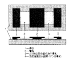
本発明は、抵抗が、酸素分圧と温度に依存するガス検出部分と、温度のみに依存する温度補償部分が、例えば、図3に示したように、基板に配置された抵抗型酸素センサ、に係るものである。ただし、基板へのガス検出部分と温度補償部分の配置は、図3のものに限定されず、例えば、1)基板の表にガス検出部分、裏に温度補償部分を配置する、2)上記1)の逆に配置する、などが可能である。ガス検出部分と温度補償部分の形態は、例えば、薄膜又は厚膜が好ましい。また、ガス検出部分と温度補償部分の抵抗値は、できるだけ近い方が望ましい。膜の大きさを変えることにより、それぞれの膜の抵抗値を制御することができる。また、電極は、図3に示した構造に限定されず、例えば、交差指型構造なども可能である。図3では、ガス検出部分と接触する電極は、ガス検出部分の上に位置するが、基板とガス検出部分との間に位置することも可能である。温度補償部分と電極の位置関係は、基板、厚膜、多孔質な電極であることが好ましい。というのも、O2-=1/2O2 +2e- の反応は、電極・厚膜・ガスの三相界面で生じるので、この反応が生じないと、イオン伝導体の抵抗が増大するためである。ただし、基板、電極、厚膜の順番であっても、厚膜が多孔質体であれば三相界面が存在するため可能である。
【0014】
基板の材料としては、絶縁体である酸化アルミナ、酸化マグネシウム、石英などが例示されるが、これらに制限されるものではない。ガス検出部分としては、酸化セリウム、酸化チタン、酸化ガリウムなどに代表される酸化物半導体が用いられる。温度補償部分としては、ガス検出部の温度依存性に近い酸素イオン伝導体、例えば、イットリア安定化ジルコニア、ガリウムド−プセリアなどが用いららる。酸化セリウムは、酸化物半導体であるが、酸化セリウムは、添加する金属イオンの種類によっては酸素イオン伝導体になることが可能である。具体的には、2、3価の金属イオンを添加すれば酸素イオン伝導体となる。
【0015】
また、酸化物半導体あるいは酸素イオン伝導体の主成分を酸化セリウムとした場合、その温度依存性は、添加するイオンの種類を変えたり、添加量を変えたりすることにより、適宜変えることが可能である。したがって、好適には、本発明のガス検出部分と温度補償部分として、酸化セリウムを主成分とした酸化物を用いることが可能であり、添加イオンの種類や量を変えれば、温度依存性を制御でき、温度依存性が極めて小さい抵抗型酸素センサを作製することができる。電極としては、Pt、Pdなどの貴金属、及び導電性酸化物などが例示されるが、これらに限定されない。温度補償部分である酸素イオン伝導体と接触する電極の形態は多孔質体でなければならない。緻密体であると、O2-=1/2O2 +2e-の反応が進行せず、温度補償部分であるイオン伝導体の抵抗が温度一定であっても必ず変動してしまう。つまり、長期安定性がなくなってしまう。このため、電極は必ず多孔質体でなければならない。ガス検出部分と接触する電極は多孔質体でなくてもよいが、温度補償部分と接触する電極を同時に作製するには、温度補償部分と接触する電極と同じ多孔質体であるほうが好ましい。なぜなら、温度補償部分と接触する電極とガス検出部分と接触するそれとの材質を異なるようにするには、それを実現するために製造工程が一工程増えるため、製造コストが増加してしまうからである。したがって、温度補償部分とガス検出部分とに接触する電極は、多孔質体であることが好ましい。
【0016】
次に、センサの作製方法を説明すると、まず、初めに、ガス検出部分と温度補償部分の作製方法であるが、薄膜の場合、作製方法としては、スパッタ法、MOCVD法、ゾルゲル法などが例示されるが、これらに限定されるものではない。これらの方法により、基板上に薄膜を作製する。成膜後、空気中1000〜1200℃で焼成する。厚膜の場合、作製方法としては、まず、酸化物半導体粉末を作製する。この作製方法として、噴霧熱分解法、スプレードライ法、沈殿法などの製法が例示されるが、これらに限定されるものではない。次に、酸化物半導体粉末とビヒクル、スキージオイル等の有機溶媒を混合し、ペーストを作製し、このペーストを基板上に印刷する。印刷方法としては、好適には、スクリーン印刷法が用いられるが、これに限定されない。
【0017】
次に、これを空気中400〜600℃で加熱して、有機溶媒を除去し、次いで、空気中1000〜1200℃で焼成する。
次に、電極を作製する。その方法として、Pt、Pdなどの貴金属ペーストをスクリーン印刷法により塗布する方法、Pt、Pdをスパッタ法により作製する方法などが例示されるが、これらに限定されない。ただし、多孔質な電極を得るには、スッパタ法より、スクリーン印刷法のほうが、容易に多孔質電極を得ることができるため、スクリーン印刷法のほうがより好ましい。電極を基板とガス検出部分や温度補償部分との間に位置させる場合、基板上に電極を作製し、その上にガス検出部分と温度補償部分をそれぞれ作製する。
【0018】
ヒータ付の抵抗型酸素センサの場合、例えば、基板にセラミックヒータ、シリコンマイクロヒータなどを取り付ける。ただし、ヒータの取り付け位置、ヒータの形状、ヒータの特性については、特に限定するものではない。なぜならば、本発明の抵抗型酸素センサは、温度依存性が小さいので、ヒータに対する要求度が小さく、ヒータの性能は重要ではないためである。
【0019】
本発明の抵抗型酸素センサは、酸素センサ装置に用いられる。この装置は、本発明の抵抗型酸素センサと電気回路部とセンサ出力などの表示部とを基本的構成要素として任意に設計することができる。図4に、この装置の電気回路の一例を示す。この図では、ヒータ部分の回路は省略してある。図中、点線で囲んだ部分が、抵抗型酸素センサである。ガス検出部分と温度補償部分を直列に接続し、一定電圧を負荷し、ガス検出部分の電位差をセンサ出力として読み取るようにすることで酸素センサ装置を作製することができる。
【0020】
本発明の抵抗型酸素センサは、例えば、空燃比を制御するための、自動車(二輪車を含む)用空燃比フィードバック制御システムに使用することができる。ここで空燃比とは、空気と燃料の比であり、酸素分圧と空燃比とは1対1の関係が成り立つ。このシステムは、本発明の抵抗型酸素センサと、エンジンに流入する空気の流量を測定する流量計と、エンジンに燃料を入れる燃料噴射器と、酸素センサや流量計からの信号を受け取り、計算を行い、燃料噴射器の燃料噴射量を制御するコントロール回路とを基本的構成要素として任意に設計することができる。
【0021】
また、本発明の抵抗型酸素センサは、例えば、燃焼機関の燃焼効率最適化のための空燃比フィードバック制御システムに使用することができる。このシステムは、本発明の抵抗型酸素センサと、燃焼機関に流入する空気の流量を測定する流量計と、燃焼機関内に入れる燃料を制御する燃料制御器と、酸素センサや流量計からの信号を受け取り、計算を行い、燃料制御器に出力信号を送る電子制御ユニットとを基本的構成要素として任意に設計することができる。
【0022】
また、本発明の抵抗型酸素センサは、例えば、自動車排ガス触媒劣化検知システムに使用することができる。このシステムは、本発明の抵抗型酸素センサと、酸素センサからの信号を読み取り計算し、触媒が劣化したかどうかを判断する電子制御ユニットと、電子制御ユニットからの信号を受けとり、触媒が劣化したかどうかを示す表示部とを基本的構成要素として任意に設計することができる。
【0023】
本発明は、小型で構造が簡単な抵抗型酸素センサにおいて、出力の温度依存性を極めて小さくすることを可能とする新しい原理の温度補償部分を有する抵抗型酸素センサを提供するものである。また、本発明は、自動車排ガス浄化用触媒の劣化を検知するための自動車排ガス触媒劣化検知システムに使用される抵抗型酸素センサを提供するものである。更に、本発明は、ボイラーなどの燃焼効率最適化のための空燃比フィードバック制御システムに使われる抵抗型酸素センサを提供するものである。
【0024】
【作用】
ガス検出部分の抵抗をrg とすると、rg は次式で与えられる。
rg =rg 0 ×P1/n ×exp(Eg /kT)
ここで、rg 0 は温度にも酸素分圧にも依存しないガス検出部分固有の定数、Pは酸素分圧、nは4から6の値、Eg はガス検出部分の活性化エネルギー、kはボルツマン定数、Tは温度である。一方、温度補償部分の抵抗をrn とすると、rn =rn 0 ×exp(En /kT)
となる。ここで、rn 0 は温度にも酸素分圧にも依存しない温度補償部分固有の定数、En は温度補償部分の活性化エネルギーである。
【0025】
一定電圧Vを図4のようにかけると、ガス検出部分における電位差Vout は、次式となる。
Vout =rg /(rg +rn )×V
=rg 0 ×P1/n ×exp(Eg /kT)/{rg 0 ×P1/n ×exp(Eg/kT)+rn 0 ×exp(En /kT)}×V
ガス検出部分と温度補償部分の活性化エネルギーが等しいならば、
Vout =rg 0 ×P1/n /(rg 0 ×P1/n +rn 0 )×V
となり、温度に依存する項は消える。つまり、センサ出力は温度に依存しない。Eg とEn が少し異なる場合、わずかに温度依存性を示すが、Eg とEn が一致するようにガス検出部分と温度補償部分の材料を選択すれば温度依存性の全くないセンサも可能である。
【0026】
酸素イオン伝導体の一般的な特徴として、酸素イオン輸率が1である酸素分圧の範囲において、抵抗は、酸素分圧に依存しない。このことをもとに、温度補償部分として、酸素イオン伝導体を使用した。これは従来技術と全く異なる発想である。抵抗が酸素分圧に依存しない酸素分圧の範囲は、一般的に広く、例えば、Gdを添加した酸化セリウムでは1atmから10-19 atmであり、Caを添加した酸化ジルコニウムでは1atmから10-30 atmである。よって、これらの材料を温度補償部分とした場合、この範囲の酸素分圧で酸素センサとして使用可能である。また、温度補償部分は、均一な酸素イオン伝導体であり、混合物ではないので、耐久性に優れ、また、作製プロセスも簡単である。
【0027】
電極は多孔質体でなければならない。酸素イオン伝導体での電荷担体は酸素イオン(O2-)である。直流である場合、負極から正極に向かって酸素イオンが流れる。このとき、負極では、電子と酸素分子から酸素イオンが生成する。
1/2O2 +2e- →O2-
この生成した酸素イオンは酸素イオン伝導体を流れ、正極において
O2-→1/2O2 +2e-
の反応が生じる。これらの反応は、電極・ガス・酸素イオン伝導体の三相界面で生じる。多孔質体であれば、この三相界面は多数あるため、酸素イオン伝導体を流れる酸素イオン(O2-)がいつも供給されるため、抵抗の変動はない。しかし、もし、この三相界面が非常に少ない場合、これらの反応はほとんど生じないため、電荷担体が少なくなり、結果として抵抗が増大する。つまり、長期安定性が欠如する。したがって、電極が多孔質体であることは、本発明が成立するための必要十分条件である。
【0028】
【実施例】
次に、実施例に基づいて本発明を具体的に説明するが、本発明は、以下の実施例によって何ら限定されるものではない。
実施例1
沈殿法により10mol%YO1.5 を含む酸化セリウム複合酸化物の微粉末を得た。得られた微粉末と、有機溶媒のビヒクルとを混合したペーストを、酸化アルミニウム基板上にスクリーン印刷により印刷した。次に、これを空気中500℃で加熱し、引き続き、空気中1200℃で加熱し、7mm×7mm、厚さ20〜40μmの温度補償部分となる厚膜を得た。
【0029】
噴霧熱分解法により得た酸化セリウムの微粉末と、有機溶媒のビヒクルとを混合したペーストを、図3に示すような温度補償部分の厚膜のとなりの直列の位置にスクリーン印刷により印刷した。次に、これを空気中500℃で加熱し、引き続き、空気中1200℃で加熱し、7mm×7mm、厚さ20〜40μmのガス検出部分となる厚膜を得た。
【0030】
白金ペースト( 田中貴金属工業株式会社製) を、図3に示すような位置に塗布し、これを1200℃で加熱することにより白金電極を設けた。電子走査顕微鏡で観察したところ電極の厚さは10μmであり、多孔質体であった。このことから、三相界面が存在することが確認できた。酸素分圧を変えることのできる測定室に、このセンサ素子を置き、図4に示すようにDC電源と電圧計を接続した。電気炉を所定の温度に上げ、DC電源にVの電圧(10V)を印加し、ガス検出部分の電位差VOut を測定した。
【0031】
ガス検出部分のX線回折分析の結果、ガス検出部分は、蛍石型構造の単一相であった。また、温度補償部分のX線回折分析の結果、温度補償部分も、蛍石型構造の単一相であった。
【0032】
図5に、750℃から1000℃におけるガス検出部分と温度補償部分の抵抗を示す。ガス検出部分と温度補償部分の抵抗の温度依存性は、ほぼ同じであった。ガス検出部分では、1atmにおける抵抗と0.01atmにおけるそれとは大きく異なるが、温度補償部分では、1atmにおける抵抗と0.01atmにおけるそれとはほぼ一致していた。以上のことから、ガス検出部分では、抵抗は温度と酸素分圧の両方に依存していること、温度補償部分では、抵抗は温度だけに依存していること、ガス検出部分と温度補償部分の温度依存性はほぼ同じであること、が確認できた。
【0033】
図6に、本発明の抵抗型酸素センサの出力の1例と、従来の抵抗型酸素センサの出力とを合わせて示す。従来のセンサの出力は、抵抗が一定の基準抵抗を使った図7に示す動作回路により得た。従来のセンサでは、850℃における0.01atmのセンサ出力と、900℃における1atmの出力とがほぼ同じであり、出力の温度依存性が極めて大きかった。一方、本発明のセンサでは、850℃における出力と900℃におけるそれとにほとんど違いがなく、出力の温度依存性が小さいことがわかった。
【0034】
図8に、750℃から1000℃における本発明の抵抗型酸素センサの出力と、従来の抵抗型酸素センサの出力とを合わせて示す。この図においても、従来の抵抗型酸素センサの出力は、図7に示す動作回路により得た。本発明のセンサ出力は、温度依存性が少し認められるが、従来のセンサに比べると格段に温度依存性が小さいことがわかった。したがって、本発明では、ガス検出部分と温度補償部分の温度依存性を同じになるようにそれぞれの材料を選択すれば、温度依存性はもっと小さくすることが原理的に可能である。
【0035】
実施例2
図9に温度補償部分であるイオン伝導体と接触する白金電極の断面図を示す。この白金電極は、白金ペースト( 田中貴金属工業株式会社製) をスクリーン印刷法で塗布し、150℃で乾燥後、1200℃において2h空気中で焼成したものである。図9からわかるように、膜厚は約10μmであり、非常に多孔質であった。
【0036】
【発明の効果】
以上詳述したように、本発明は、抵抗型酸素センサとそれを使った酸素センサ装置及び空燃比制御システムに係るものであり、本発明により、以下のような効果が奏される。
(1)従来の抵抗型酸素センサでは、温度依存性が極めて大きく、センサの温度を非常に精度よく制御しなければならなかったが、本発明のセンサでは、多少温度がずれてもセンサ出力にほとんど影響がないため、温度制御に対する要求度が緩和されるという効果がある。
(2)温度補償部分が混合物でなく単一相のものであるので作製プロセスが簡単であり、ガラスシールなどを使用しないので熱衝撃などに強く耐久性がある。
(3)広い酸素分圧範囲で酸素センサとして使用可能である。
【0037】
(4)酸化セリウムは、添加する金属イオンによって、酸化物半導体(電子導電体)になったり、酸素イオン導電体になったりする。したがって、本発明では、ガス検出部分と温度補償部分を酸化セリウムが主成分の材料にすることが可能である。
(5)酸化セリウムは、腐食性ガスに対して耐久性があるため、本発明は、酸化セリウムを主成分として使った場合、特に長期安定性に優れた抵抗型酸素センサが得られる。
【図面の簡単な説明】
【図1】従来技術において、温度補償部分の抵抗と酸素分圧の関係を、並列の等価回路を使って計算した結果である。
【図2】従来技術において、温度補償部分の抵抗と酸素分圧の関係を、直列の等価回路を使って計算した結果である。
【図3】本発明の抵抗型酸素センサの構造を示す正面図及び側面図である。
【図4】本発明の抵抗型酸素センサの動作を示す回路図である。
【図5】本発明の抵抗型酸素センサのガス検出部分と温度補償部分の酸素分圧1、0.01atmにおける抵抗を示すグラフである。
【図6】本発明の抵抗型酸素センサの出力の1例と、従来の抵抗型酸素センサの出力を示すグラフである。
【図7】従来の抵抗型酸素センサの動作を示す回路図である。
【図8】750℃から1000℃における本発明の抵抗型酸素センサの出力と、従来の抵抗型酸素センサの出力とを示すグラフである。
【図9】温度補償部分であるイオン伝導体と接触する白金電極の断面図である。[0001]
BACKGROUND OF THE INVENTION
The present invention relates to a resistance-type oxygen sensor with reduced temperature dependence, and more specifically, has a gas detection portion made of an oxide semiconductor whose resistance value changes according to the oxygen partial pressure of the atmospheric gas. The present invention relates to a resistance type oxygen sensor with reduced temperature dependence. The present invention measures oxygen partial pressure with high accuracy, which is preferably used in an air-fuel ratio feedback control system for controlling an air-fuel ratio of an automobile combustion engine or the like for improving the purification rate of exhaust gas and improving fuel efficiency. The present invention is useful for providing a new oxygen sensor device that makes it possible.
[0002]
[Prior art]
In a conventional resistance type oxygen sensor using an oxide semiconductor, the resistance value of the oxide semiconductor, which is a gas detection part, shows a strong dependence not only on oxygen partial pressure but also on temperature. There was a problem that the temperature dependence was very large.
Conventionally, the following four methods are known as methods for realizing the characteristic that the resistance is not dependent on the oxygen partial pressure, that is, the oxygen insensitivity of the resistance, which is necessary as a temperature compensation portion of the sensor. They are listed below.
[0003]
First, one is M.I. J. et al. As reported by Esper et al. (See Non-Patent Document 1), they used high-density titanium oxide as a temperature compensation portion insensitive to oxygen gas. In this case, the resistance is oxygen insensitive in the short term, but has a problem that it depends on the oxygen partial pressure in the long term.
[0004]
Second, a gas sensor having a temperature compensation portion that is insensitive to oxygen gas (see
[0005]
Thirdly, a method of obtaining a non-sensitive part by doping a metal atom such as gold to such an extent that gas sensitivity is lost (see
[0006]
Fourthly, in a recent report, a mixture of p-type and n-type oxide semiconductors is used as a temperature compensation portion (see Patent Document 5), and p-type and n-type oxide semiconductors are used. A thin film is used (see Patent Document 6). However, these temperature compensation parts are problematic in that long-term stability cannot be obtained due to the reaction between the p-type and n-type oxide semiconductors at the sensor operating temperature, and the thermal expansion coefficient of those materials. There is a problem that cracks and the like occur due to the difference.
[0007]
In addition, when making a laminated structure of p-type and n-type oxide semiconductors as the insensitive part, it is necessary to control the thin film production conditions with high precision in order to make a good stack, and as the temperature compensation part, When making a mixture of p-type and n-type oxide semiconductors, it is necessary to control the mixing so that both oxide semiconductors are neatly dispersed. Therefore, the manufacturing process of the insensitive portion is complicated. There is also.
[0008]
Furthermore, these documents do not show that the temperature compensation portion is independent of oxygen partial pressure, or even if shown, the range of oxygen partial pressure is shown only in two digits. In the case of these prior arts, it is presumed that the range in which the resistance of the temperature compensation portion does not depend on the oxygen partial pressure is small in principle. More specifically, in the p type, the resistance r is proportional to the oxygen partial pressure P to the power of -1 / n, and in the n type, r is proportional to the power of P to the 1 / n power. Here, n is 4 to 6. When an equivalent circuit is considered, the parallel circuit should change as shown in FIG. 1, and the series circuit should change as shown in FIG. Therefore, the range that does not depend on the oxygen partial pressure is small, and if the oxygen partial pressure deviates from this range, the oxygen partial pressure dependency of the sensor output becomes extremely small. In addition, these documents do not indicate that the output of the oxygen sensor does not depend on temperature or that temperature dependency is small.
[0009]
[Patent Document 1]
European Patent Application No. 0464243
[Patent Document 2]
Published European Patent Application No. 0464244
[Patent Document 3]
German Patent No. 4210397
[Patent Document 4]
German Patent No. 4210398
[Patent Document 5]
JP-A-6-222026
[Patent Document 6]
Japanese National Patent Publication No. 10-505164
[Non-Patent Document 1]
SAE Technical Paper, (1979), 790140
[0010]
[Problems to be solved by the invention]
Under such circumstances, in view of the prior art, the present inventors realize the oxygen insensitivity of the resistance of the temperature compensation portion by a method different from the prior art, and the temperature compensation portion. As a result of diligent research, the process of producing oxygen was simple, and it was resistant to thermal shock, durable, and insensitive to oxygen in a wide oxygen partial pressure range. The resistance value of the ion conductor utilizes the property that the oxygen partial pressure dependency is extremely small, and the temperature compensation portion is composed of the oxygen ion conductor, and the electrode for making electrical contact with the temperature compensation portion is the atmospheric gas. It has been found that the intended object can be achieved by facing the porous body, and the present invention has been completed.
[0011]
That is, the present invention has a gas detection part made of an oxide semiconductor whose resistance value changes according to the temperature and the oxygen partial pressure of the atmospheric gas, and the resistance depends on the temperature, but the oxygen partial pressure An object of the present invention is to provide a resistance type oxygen sensor in which an independent temperature compensation portion is connected in series to the gas detection portion. In addition, the present invention mainly includes a temperature compensation portion based on a principle different from that of the prior art in a resistance type oxygen sensor used for measuring the oxygen gas partial pressure of automobile exhaust gas. It is an object of the present invention to provide a resistance type oxygen sensor in which an electrode for contacting the surface faces an atmospheric gas and is a porous body. Furthermore, the present invention is a resistance-type oxygen that has a simple manufacturing process, is resistant to thermal shock, is durable, can be used as an oxygen sensor in a wide oxygen partial pressure range, and has low temperature dependence of output. The object is to provide a sensor.
[0012]
[Means for Solving the Problems]
The present invention for solving the above-described problems comprises the following technical means.
(1) A resistance type oxygen sensor with reduced temperature dependence,
(A) A gas detection portion made of an oxide semiconductor whose resistance value changes in accordance with the temperature and the oxygen partial pressure of the atmospheric gas, and a temperature compensation portion made of a conductor that suppresses the oxygen partial pressure dependency of the resistance value in series. ConnectionHave a structuredTo
(B) Temperature compensation partButConsists of oxygen ion conductorBeing
(C) the electrode for making electrical contact with the temperature compensation portion faces the atmospheric gas;as well as
(D) The form of the temperature compensation portion is a thin film or a thick film, the film and the electrode have a positional relationship in which the substrate, the film, and the electrode are laminated in this order, and the electrode is a porous body, or The film and the electrode have a positional relationship in which the substrate, the electrode, and the film are stacked in this order, and the film is a porous body.
A resistance type oxygen sensor.
(2The temperature compensation part is similar to that of the gas detection part in that its temperature dependency is used.1)The resistance type oxygen sensor described.
(3) The temperature compensation portion is the one having the same temperature dependency as that of the gas detection portion.1)The resistance type oxygen sensor described.
(4) The oxide semiconductor as the gas detection part is cerium oxide or a composite oxide containing cerium oxide as a main component.1)The resistance type oxygen sensor described.
(5) The oxygen ion conductor as the temperature compensation portion is a composite oxide containing cerium oxide as a main component,1)The resistance type oxygen sensor described.
(6(1) From the above (1),5) The resistance type oxygen sensor according to any one of the above.
(7) From (1) to (6The oxygen sensor device comprising the resistance oxygen sensor according to
(8A) means capable of loading a constant voltage; and means capable of measuring the voltage.7) Oxygen sensor device.
(9) From (1) to (6The air-fuel ratio feedback control system for controlling the air-fuel ratio of the combustion engine, comprising the resistance oxygen sensor according to any one of the above.
(10) Control the air-fuel ratio for automobiles,9) The air-fuel ratio feedback control system described.
(11) From (1) to (7), A resistance type oxygen sensor according to any one of
[0013]
DETAILED DESCRIPTION OF THE INVENTION
Next, the present invention will be described in more detail.
The present invention relates to a resistance type oxygen sensor in which a gas detection portion whose resistance depends on oxygen partial pressure and temperature and a temperature compensation portion whose resistance depends only on temperature are arranged on a substrate as shown in FIG. It is related to. However, the arrangement of the gas detection portion and the temperature compensation portion on the substrate is not limited to that shown in FIG. 3. For example, 1) the gas detection portion is arranged on the front side of the substrate, and the temperature compensation portion is arranged on the back side. It is possible to arrange them in the opposite order. For example, the gas detection part and the temperature compensation part are preferably a thin film or a thick film. Further, it is desirable that the resistance values of the gas detection portion and the temperature compensation portion be as close as possible. By changing the size of the film, the resistance value of each film can be controlled. Further, the electrodes are not limited to the structure shown in FIG. 3, and for example, a cross finger type structure or the like is possible. In FIG. 3, the electrode in contact with the gas detection portion is located on the gas detection portion, but may be located between the substrate and the gas detection portion. The positional relationship between the temperature compensation portion and the electrode is preferably a substrate, a thick film, or a porous electrode. Because O2-= 1 / 2O2 + 2e- This reaction occurs at the three-phase interface of the electrode, the thick film, and the gas, and if this reaction does not occur, the resistance of the ionic conductor increases. However, even in the order of the substrate, electrode, and thick film, if the thick film is a porous body, it is possible because a three-phase interface exists.
[0014]
Examples of the material of the substrate include, but are not limited to, alumina oxide, magnesium oxide, and quartz that are insulators. As the gas detection portion, an oxide semiconductor typified by cerium oxide, titanium oxide, gallium oxide, or the like is used. As the temperature compensation part, an oxygen ion conductor close to the temperature dependence of the gas detection part, for example, yttria-stabilized zirconia, gallium doped pseria, or the like is used. Cerium oxide is an oxide semiconductor, but cerium oxide can be an oxygen ion conductor depending on the type of metal ions to be added. Specifically, if a divalent or trivalent metal ion is added, an oxygen ion conductor is obtained.
[0015]
In addition, when the main component of the oxide semiconductor or oxygen ion conductor is cerium oxide, its temperature dependence can be changed as appropriate by changing the type of ion to be added or the amount of addition. is there. Therefore, it is preferable to use an oxide mainly composed of cerium oxide as the gas detection part and temperature compensation part of the present invention, and the temperature dependence can be controlled by changing the kind and amount of the added ions. In addition, it is possible to manufacture a resistance-type oxygen sensor with extremely low temperature dependency. Examples of the electrode include, but are not limited to, noble metals such as Pt and Pd, and conductive oxides. The form of the electrode in contact with the oxygen ion conductor that is the temperature compensation portion must be a porous body. If it is a dense body, O2-= 1 / 2O2 + 2e-This reaction does not proceed, and the resistance of the ion conductor, which is the temperature compensation portion, always fluctuates even if the temperature is constant. In other words, long-term stability is lost. For this reason, the electrode must be a porous body. The electrode in contact with the gas detection portion may not be a porous body. However, in order to simultaneously produce the electrode in contact with the temperature compensation portion, the same porous body as the electrode in contact with the temperature compensation portion is preferable. This is because, in order to achieve a different material for the electrode in contact with the temperature compensation portion and the material in contact with the gas detection portion, the manufacturing process increases by one step, which increases the manufacturing cost. is there. Therefore, the electrode in contact with the temperature compensation portion and the gas detection portion is preferably a porous body.
[0016]
Next, a sensor manufacturing method will be described. First, a gas detection portion and a temperature compensation portion are manufactured. In the case of a thin film, examples of the manufacturing method include a sputtering method, an MOCVD method, and a sol-gel method. However, it is not limited to these. A thin film is produced on a substrate by these methods. After film formation, baking is performed at 1000 to 1200 ° C. in air. In the case of a thick film, as a manufacturing method, first, an oxide semiconductor powder is manufactured. Examples of the production method include production methods such as spray pyrolysis, spray drying, and precipitation, but are not limited thereto. Next, an oxide semiconductor powder and an organic solvent such as a vehicle and squeegee oil are mixed to produce a paste, and this paste is printed on a substrate. A screen printing method is preferably used as the printing method, but is not limited thereto.
[0017]
Next, this is heated at 400 to 600 ° C. in the air to remove the organic solvent, and then baked at 1000 to 1200 ° C. in the air.
Next, an electrode is produced. Examples of the method include, but are not limited to, a method of applying a noble metal paste such as Pt and Pd by a screen printing method, a method of producing Pt and Pd by a sputtering method, and the like. However, in order to obtain a porous electrode, the screen printing method is more preferable than the sputtering method, because the porous electrode can be obtained more easily than the screen printing method. When the electrode is positioned between the substrate and the gas detection portion or the temperature compensation portion, the electrode is produced on the substrate, and the gas detection portion and the temperature compensation portion are produced thereon.
[0018]
In the case of a resistance type oxygen sensor with a heater, for example, a ceramic heater, a silicon micro heater, or the like is attached to the substrate. However, the attachment position of the heater, the shape of the heater, and the characteristics of the heater are not particularly limited. This is because the resistance-type oxygen sensor of the present invention has a small temperature dependency, and thus the degree of demand for the heater is small, and the performance of the heater is not important.
[0019]
The resistance oxygen sensor of the present invention is used in an oxygen sensor device. This device can be arbitrarily designed with the resistance oxygen sensor of the present invention, an electric circuit unit, and a display unit such as a sensor output as basic components. FIG. 4 shows an example of an electric circuit of this apparatus. In this figure, the circuit of the heater portion is omitted. In the figure, the portion surrounded by a dotted line is a resistance type oxygen sensor. An oxygen sensor device can be manufactured by connecting a gas detection part and a temperature compensation part in series, loading a constant voltage, and reading the potential difference of the gas detection part as a sensor output.
[0020]
The resistance-type oxygen sensor of the present invention can be used, for example, in an air-fuel ratio feedback control system for automobiles (including motorcycles) for controlling the air-fuel ratio. Here, the air-fuel ratio is the ratio of air to fuel, and the oxygen partial pressure and the air-fuel ratio have a one-to-one relationship. This system receives the signals from the resistance type oxygen sensor of the present invention, the flow meter that measures the flow rate of air flowing into the engine, the fuel injector that puts fuel into the engine, and the oxygen sensor and flow meter. And a control circuit for controlling the fuel injection amount of the fuel injector can be arbitrarily designed as a basic component.
[0021]
The resistance oxygen sensor of the present invention can be used, for example, in an air-fuel ratio feedback control system for optimizing the combustion efficiency of a combustion engine. This system includes a resistance-type oxygen sensor of the present invention, a flow meter that measures the flow rate of air flowing into the combustion engine, a fuel controller that controls the fuel that enters the combustion engine, and signals from the oxygen sensor and the flow meter. The electronic control unit can be arbitrarily designed as a basic component, receiving and calculating and sending an output signal to the fuel controller.
[0022]
The resistance oxygen sensor of the present invention can be used for, for example, an automobile exhaust gas catalyst deterioration detection system. This system includes a resistance-type oxygen sensor of the present invention, an electronic control unit that reads and calculates a signal from the oxygen sensor, determines whether the catalyst has deteriorated, receives a signal from the electronic control unit, and the catalyst has deteriorated. It is possible to arbitrarily design a display unit indicating whether or not as a basic component.
[0023]
The present invention provides a resistance type oxygen sensor having a temperature compensation portion based on a new principle that makes it possible to make the temperature dependency of the output extremely small in a small size and simple resistance type oxygen sensor. The present invention also provides a resistance-type oxygen sensor used in an automobile exhaust gas catalyst deterioration detection system for detecting deterioration of an automobile exhaust gas purification catalyst. Furthermore, the present invention provides a resistance type oxygen sensor used in an air-fuel ratio feedback control system for optimizing combustion efficiency of a boiler or the like.
[0024]
[Action]
The resistance of the gas detection part is rg Then rg Is given by:
rg = Rg 0 × P1 / n Xexp (Eg / KT)
Where rg 0 Is a constant specific to the gas detection part that does not depend on temperature or oxygen partial pressure, P is oxygen partial pressure, n is a value from 4 to 6, Eg Is the activation energy of the gas detection part, k is the Boltzmann constant, and T is the temperature. On the other hand, the resistance of the temperature compensation portion is rn Then rn = Rn 0 Xexp (En / KT)
It becomes. Where rn 0 Is a constant specific to the temperature compensation part that does not depend on temperature or oxygen partial pressure, EnIs the activation energy of the temperature compensation portion.
[0025]
When a constant voltage V is applied as shown in FIG.out Is given by
Vout = Rg / (Rg + Rn ) × V
= Rg 0 × P1 / n Xexp (Eg / KT) / {rg 0 × P1 / n Xexp (Eg/ KT) + rn 0 Xexp (En / KT)} × V
If the activation energy of the gas detection part and the temperature compensation part are equal,
Vout = Rg 0 × P1 / n / (Rg 0× P1 / n + Rn 0 ) × V
And the temperature-dependent term disappears. That is, the sensor output does not depend on the temperature. When Eg and En are slightly different, there is a slight temperature dependence.gAnd En If the materials of the gas detection portion and the temperature compensation portion are selected so that the two coincide, a sensor having no temperature dependence is possible.
[0026]
As a general feature of the oxygen ion conductor, in the range of the oxygen partial pressure where the oxygen ion transport number is 1, the resistance does not depend on the oxygen partial pressure. Based on this, an oxygen ion conductor was used as a temperature compensation portion. This is a completely different idea from the prior art. The range of the oxygen partial pressure whose resistance does not depend on the oxygen partial pressure is generally wide. For example, cerium oxide to which Gd is added has a range of 1 atm to 10 atm.-19Atm and zirconium oxide added with Ca from 1 atm to 10-30 atm. Therefore, when these materials are used as temperature compensation parts, they can be used as oxygen sensors with an oxygen partial pressure in this range. Further, the temperature compensation portion is a uniform oxygen ion conductor and is not a mixture, so that it has excellent durability and a simple manufacturing process.
[0027]
The electrode must be porous. The charge carriers in the oxygen ion conductor are oxygen ions (O2-). In the case of direct current, oxygen ions flow from the negative electrode toward the positive electrode. At this time, oxygen ions are generated from electrons and oxygen molecules in the negative electrode.
1 / 2O2 + 2e- → O2-
The generated oxygen ions flow through the oxygen ion conductor and in the positive electrode.
O2-→ 1 / 2O2 + 2e-
Reaction occurs. These reactions occur at the three-phase interface of the electrode, gas, and oxygen ion conductor. In the case of a porous body, since there are many three-phase interfaces, oxygen ions (O2-) Is always supplied, so there is no resistance variation. However, if this three-phase interface is very few, these reactions rarely occur, resulting in fewer charge carriers and consequently increased resistance. In short, long-term stability is lacking. Therefore, it is a necessary and sufficient condition for the present invention to be established that the electrode is a porous body.
[0028]
【Example】
EXAMPLES Next, although this invention is demonstrated concretely based on an Example, this invention is not limited at all by the following Examples.
Example 1
10 mol% YO by precipitation1.5 A fine powder of cerium oxide composite oxide containing was obtained. A paste obtained by mixing the obtained fine powder and an organic solvent vehicle was printed on an aluminum oxide substrate by screen printing. Next, this was heated at 500 ° C. in the air, and subsequently heated at 1200 ° C. in the air to obtain a thick film serving as a temperature compensation portion of 7 mm × 7 mm and a thickness of 20 to 40 μm.
[0029]
A paste obtained by mixing fine powder of cerium oxide obtained by spray pyrolysis and a vehicle of an organic solvent was printed by screen printing at a serial position next to the thick film of the temperature compensation portion as shown in FIG. Next, this was heated at 500 ° C. in the air, and subsequently heated at 1200 ° C. in the air to obtain a thick film serving as a gas detection portion of 7 mm × 7 mm and a thickness of 20 to 40 μm.
[0030]
A platinum paste (manufactured by Tanaka Kikinzoku Kogyo Co., Ltd.) was applied to a position as shown in FIG. 3 and heated at 1200 ° C. to provide a platinum electrode. When observed with an electron scanning microscope, the thickness of the electrode was 10 μm, and it was a porous body. From this, it was confirmed that a three-phase interface was present. This sensor element was placed in a measurement chamber capable of changing the oxygen partial pressure, and a DC power source and a voltmeter were connected as shown in FIG. Raise the electric furnace to a predetermined temperature, apply a V voltage (10V) to the DC power supply,OutWas measured.
[0031]
As a result of X-ray diffraction analysis of the gas detection portion, the gas detection portion was a single phase having a fluorite structure. As a result of X-ray diffraction analysis of the temperature compensation portion, the temperature compensation portion was also a single phase having a fluorite structure.
[0032]
FIG. 5 shows the resistance of the gas detection portion and the temperature compensation portion from 750 ° C. to 1000 ° C. The temperature dependence of the resistance of the gas detection portion and the temperature compensation portion was almost the same. In the gas detection portion, the resistance at 1 atm and the resistance at 0.01 atm are greatly different, but in the temperature compensation portion, the resistance at 1 atm and the resistance at 0.01 atm are almost the same. From the above, in the gas detection part, the resistance depends on both the temperature and the oxygen partial pressure, in the temperature compensation part, the resistance depends only on the temperature, the gas detection part and the temperature compensation part It was confirmed that the temperature dependence was almost the same.
[0033]
FIG. 6 shows an example of the output of the resistance oxygen sensor of the present invention together with the output of the conventional resistance oxygen sensor. The output of the conventional sensor was obtained by the operation circuit shown in FIG. 7 using a reference resistor having a constant resistance. In the conventional sensor, the sensor output of 0.01 atm at 850 ° C. and the output of 1 atm at 900 ° C. are almost the same, and the temperature dependence of the output is extremely large. On the other hand, in the sensor of the present invention, it was found that there was almost no difference between the output at 850 ° C. and that at 900 ° C., and the temperature dependency of the output was small.
[0034]
FIG. 8 shows the output of the resistance oxygen sensor of the present invention at 750 ° C. to 1000 ° C. together with the output of the conventional resistance oxygen sensor. Also in this figure, the output of the conventional resistance-type oxygen sensor was obtained by the operation circuit shown in FIG. The sensor output of the present invention shows a little temperature dependence, but it was found that the temperature dependence is much smaller than that of the conventional sensor. Therefore, in the present invention, if the respective materials are selected so that the temperature dependency of the gas detection portion and the temperature compensation portion are the same, the temperature dependency can be made smaller in principle.
[0035]
Example 2
FIG. 9 shows a cross-sectional view of a platinum electrode in contact with an ionic conductor as a temperature compensation portion. This platinum electrode is obtained by applying a platinum paste (manufactured by Tanaka Kikinzoku Kogyo Co., Ltd.) by screen printing, drying at 150 ° C., and firing in air at 1200 ° C. for 2 hours. As can be seen from FIG. 9, the film thickness was about 10 μm and was very porous.
[0036]
【The invention's effect】
As described above in detail, the present invention relates to a resistance-type oxygen sensor, an oxygen sensor device using the resistance-type oxygen sensor, and an air-fuel ratio control system. The present invention provides the following effects.
(1) In the conventional resistance type oxygen sensor, the temperature dependence is extremely large, and the temperature of the sensor has to be controlled very accurately. Since there is almost no influence, there is an effect that the degree of demand for temperature control is relaxed.
(2) Since the temperature compensation portion is not a mixture but a single phase, the manufacturing process is simple, and since a glass seal or the like is not used, it is highly resistant to thermal shock and is durable.
(3) It can be used as an oxygen sensor in a wide oxygen partial pressure range.
[0037]
(4) Cerium oxide becomes an oxide semiconductor (electronic conductor) or an oxygen ion conductor depending on the metal ions to be added. Therefore, in the present invention, the gas detection portion and the temperature compensation portion can be made of cerium oxide as a main component material.
(5) Since cerium oxide has durability against corrosive gas, the present invention can provide a resistance-type oxygen sensor having particularly excellent long-term stability when cerium oxide is used as a main component.
[Brief description of the drawings]
FIG. 1 is a result of calculating the relationship between resistance of a temperature compensation portion and oxygen partial pressure using a parallel equivalent circuit in the prior art.
FIG. 2 is a result of calculating the relationship between the resistance of the temperature compensation portion and the oxygen partial pressure using a series equivalent circuit in the prior art.
FIGS. 3A and 3B are a front view and a side view showing a structure of a resistance type oxygen sensor of the present invention. FIGS.
FIG. 4 is a circuit diagram showing the operation of the resistance-type oxygen sensor of the present invention.
FIG. 5 is a graph showing resistance at a partial pressure of oxygen of 0.01 atm in a gas detection portion and a temperature compensation portion of a resistance type oxygen sensor of the present invention.
FIG. 6 is a graph showing an example of the output of a resistance oxygen sensor of the present invention and the output of a conventional resistance oxygen sensor.
FIG. 7 is a circuit diagram showing the operation of a conventional resistance oxygen sensor.
FIG. 8 is a graph showing the output of the resistance oxygen sensor of the present invention at 750 ° C. to 1000 ° C. and the output of a conventional resistance oxygen sensor.
FIG. 9 is a cross-sectional view of a platinum electrode in contact with an ion conductor that is a temperature compensation portion.
Claims (11)
(1)温度及び雰囲気ガスの酸素分圧に応じて抵抗値が変化する酸化物半導体からなるガス検出部分と、抵抗値の酸素分圧依存性を抑えた導体からなる温度補償部分とを直列に接続した構造を有する、
(2)前記温度補償部分が酸素イオン伝導体で構成されている、
(3)前記温度補償部分と電気的に接触するための電極が雰囲気ガスに面している、及び
(4)温度補償部分の形態が、薄膜又は厚膜であり、該膜と電極が、基板、膜、電極の順に積層する位置関係を有し、かつ電極が多孔質体である、又は、該膜と電極が、基板、電極、膜の順に積層する位置関係を有し、かつ膜が多孔質体である、
ことを特徴とする抵抗型酸素センサ。A resistance oxygen sensor with reduced temperature dependence,
(1) A gas detection portion made of an oxide semiconductor whose resistance value changes according to the temperature and the oxygen partial pressure of the atmospheric gas, and a temperature compensation portion made of a conductor that suppresses the oxygen partial pressure dependency of the resistance value in series. to have a connection structure,
(2) The temperature compensation portion is composed of an oxygen ion conductor .
(3) an electrode for making electrical contact with the temperature compensation portion faces the atmospheric gas; and
(4) The form of the temperature compensation portion is a thin film or a thick film, the film and the electrode have a positional relationship in which the substrate, the film and the electrode are laminated in this order, and the electrode is a porous body, or The film and the electrode have a positional relationship in which the substrate, the electrode, and the film are stacked in this order, and the film is a porous body.
A resistance type oxygen sensor.
Priority Applications (1)
| Application Number | Priority Date | Filing Date | Title |
|---|---|---|---|
| JP2003180589A JP3903181B2 (en) | 2002-06-27 | 2003-06-25 | Resistance oxygen sensor, oxygen sensor device using the same, and air-fuel ratio control system |
Applications Claiming Priority (2)
| Application Number | Priority Date | Filing Date | Title |
|---|---|---|---|
| JP2002188650 | 2002-06-27 | ||
| JP2003180589A JP3903181B2 (en) | 2002-06-27 | 2003-06-25 | Resistance oxygen sensor, oxygen sensor device using the same, and air-fuel ratio control system |
Publications (3)
| Publication Number | Publication Date |
|---|---|
| JP2004085549A JP2004085549A (en) | 2004-03-18 |
| JP2004085549A5 JP2004085549A5 (en) | 2005-06-02 |
| JP3903181B2 true JP3903181B2 (en) | 2007-04-11 |
Family
ID=32071750
Family Applications (1)
| Application Number | Title | Priority Date | Filing Date |
|---|---|---|---|
| JP2003180589A Expired - Lifetime JP3903181B2 (en) | 2002-06-27 | 2003-06-25 | Resistance oxygen sensor, oxygen sensor device using the same, and air-fuel ratio control system |
Country Status (1)
| Country | Link |
|---|---|
| JP (1) | JP3903181B2 (en) |
Families Citing this family (6)
| Publication number | Priority date | Publication date | Assignee | Title |
|---|---|---|---|---|
| JP4431680B2 (en) * | 2004-03-22 | 2010-03-17 | 独立行政法人産業技術総合研究所 | Output stabilization method for resistive oxygen sensor using cerium oxide |
| JP4625930B2 (en) * | 2004-10-19 | 2011-02-02 | 独立行政法人産業技術総合研究所 | Resistive oxygen sensor and air-fuel ratio control system using it |
| JP2007008775A (en) * | 2005-06-30 | 2007-01-18 | National Institute Of Advanced Industrial & Technology | Porous zirconia thick film and method of manufacturing the same |
| JP4625931B2 (en) * | 2006-05-26 | 2011-02-02 | 独立行政法人産業技術総合研究所 | Resistive oxygen sensor element without temperature dependency of output |
| JP5112266B2 (en) * | 2007-11-30 | 2013-01-09 | ヤマハ発動機株式会社 | Control device for oxygen sensor for motor vehicle, air-fuel ratio control device including the same, and motor vehicle |
| JP6442574B2 (en) * | 2017-03-16 | 2018-12-19 | 太平洋セメント株式会社 | Nanoparticle aggregate, nanoparticle fired product, and production method thereof |
Family Cites Families (8)
| Publication number | Priority date | Publication date | Assignee | Title |
|---|---|---|---|---|
| JPS5790147A (en) * | 1980-11-26 | 1982-06-04 | Toyota Central Res & Dev Lab Inc | Air-fuel ratio gauge |
| JPS57132051A (en) * | 1981-02-10 | 1982-08-16 | Ngk Spark Plug Co Ltd | Air-fuel ratio measuring sensor and air-fuel ratio measuring method using said sensor |
| JPS5824850A (en) * | 1981-08-07 | 1983-02-14 | Toyota Central Res & Dev Lab Inc | Film type oxygen sensor with heater and oxygen detector employing said sensor |
| JP2695938B2 (en) * | 1989-09-18 | 1998-01-14 | 日本特殊陶業株式会社 | Gas detector |
| DE59009246D1 (en) * | 1990-07-04 | 1995-07-20 | Siemens Ag | Oxygen sensor with semiconducting gallium oxide. |
| ATE123877T1 (en) * | 1990-07-04 | 1995-06-15 | Siemens Ag | SENSOR FOR DETECTING REDUCING GASES. |
| JP2811976B2 (en) * | 1991-02-26 | 1998-10-15 | トヨタ自動車株式会社 | Oxide semiconductor gas sensor |
| DE4432729C1 (en) * | 1994-09-14 | 1996-04-11 | Siemens Ag | Gas sensor |
-
2003
- 2003-06-25 JP JP2003180589A patent/JP3903181B2/en not_active Expired - Lifetime
Also Published As
| Publication number | Publication date |
|---|---|
| JP2004085549A (en) | 2004-03-18 |
Similar Documents
| Publication | Publication Date | Title |
|---|---|---|
| EP0001510B1 (en) | Gas sensor | |
| US6514397B2 (en) | Gas sensor | |
| GB2050625A (en) | Device for detection of oxygen concentration in combustion gas | |
| US4629549A (en) | Oxygen sensor | |
| US7236083B2 (en) | Resistance type oxygen sensor and oxygen sensor device using it and air/fuel ratio control system | |
| JP3903181B2 (en) | Resistance oxygen sensor, oxygen sensor device using the same, and air-fuel ratio control system | |
| JP3870261B2 (en) | Resistance oxygen sensor, oxygen sensor device using the same, and air-fuel ratio control system | |
| JP4671253B2 (en) | Combustible gas concentration measuring device | |
| JP4625930B2 (en) | Resistive oxygen sensor and air-fuel ratio control system using it | |
| JPH1172476A (en) | Nitrogen oxide gas sensor | |
| EP0853239A2 (en) | Gas sensor and heater unit | |
| JP4625931B2 (en) | Resistive oxygen sensor element without temperature dependency of output | |
| JP2004325218A (en) | Temperature control device, temperature control method, and gas detection device using them | |
| JP4171803B2 (en) | Oxygen sensor using oxide semiconductor | |
| JP2002156355A (en) | Gas sensor element and gas concentration measuring device having the same | |
| JPS6332134B2 (en) | ||
| JP2002005883A (en) | Nitrogen oxide gas sensor | |
| JP2881426B2 (en) | Oxygen sensor | |
| JP2002071641A (en) | Complex gas detector | |
| Sekhar et al. | Application of commercial automotive sensor manufacturing methods for NOx/NH3 mixed potential sensors for vehicle on-board emissions control | |
| JP2008083007A (en) | Nitrogen oxide detecting element | |
| JP3415676B2 (en) | Gas sensor | |
| JPH0550702B2 (en) | ||
| JPH0514861B2 (en) | ||
| JPS63165745A (en) | Gas detector |
Legal Events
| Date | Code | Title | Description |
|---|---|---|---|
| A521 | Request for written amendment filed |
Free format text: JAPANESE INTERMEDIATE CODE: A523 Effective date: 20040819 |
|
| A621 | Written request for application examination |
Free format text: JAPANESE INTERMEDIATE CODE: A621 Effective date: 20050315 |
|
| A977 | Report on retrieval |
Free format text: JAPANESE INTERMEDIATE CODE: A971007 Effective date: 20060905 |
|
| A131 | Notification of reasons for refusal |
Free format text: JAPANESE INTERMEDIATE CODE: A131 Effective date: 20060919 |
|
| A521 | Request for written amendment filed |
Free format text: JAPANESE INTERMEDIATE CODE: A523 Effective date: 20061114 |
|
| TRDD | Decision of grant or rejection written | ||
| A01 | Written decision to grant a patent or to grant a registration (utility model) |
Free format text: JAPANESE INTERMEDIATE CODE: A01 Effective date: 20061212 |
|
| R150 | Certificate of patent or registration of utility model |
Ref document number: 3903181 Country of ref document: JP Free format text: JAPANESE INTERMEDIATE CODE: R150 Free format text: JAPANESE INTERMEDIATE CODE: R150 |
|
| S533 | Written request for registration of change of name |
Free format text: JAPANESE INTERMEDIATE CODE: R313533 |
|
| R350 | Written notification of registration of transfer |
Free format text: JAPANESE INTERMEDIATE CODE: R350 |
|
| EXPY | Cancellation because of completion of term |