JP3902811B2 - Pantograph boat support structure - Google Patents
Pantograph boat support structure Download PDFInfo
- Publication number
- JP3902811B2 JP3902811B2 JP15719896A JP15719896A JP3902811B2 JP 3902811 B2 JP3902811 B2 JP 3902811B2 JP 15719896 A JP15719896 A JP 15719896A JP 15719896 A JP15719896 A JP 15719896A JP 3902811 B2 JP3902811 B2 JP 3902811B2
- Authority
- JP
- Japan
- Prior art keywords
- sliding plate
- hull
- airfoil
- pantograph
- support
- Prior art date
- Legal status (The legal status is an assumption and is not a legal conclusion. Google has not performed a legal analysis and makes no representation as to the accuracy of the status listed.)
- Expired - Lifetime
Links
Images


Landscapes
- Current-Collector Devices For Electrically Propelled Vehicles (AREA)
Description
【0001】
【発明の属する技術分野】
本発明は、鉄道車両用パンタグラフで集電用のすり板を舟体で支えるための構造、特に舟体として低騒音化のために翼型プロフィールを使用する場合のパンタグラフ舟体のすり板支持構造に関する。
【0002】
【従来の技術】
従来から、車両の上方に架設された架線から集電する装置として、パンタグラフが広く用いられている。図9および図10は、菱型パンタグラフの集電のための構成を簡略化して示す。架線に直接摺動して集電するすり板1は、舟体に着脱可能に取付けられる。舟体2は、パンタグラフの枠体3の上部の軸4を中心として、角変位可能な2つの部分に分割されて構成される。分割された各部分間は、横ばね5によって下方からばね付勢される。さらに枠体3の上部と個々の舟体2との間には、縦ばね6がそれぞれ設けられる。すり板1は、ボルト7を介して舟体2の上面に設けられる。すり板1の上面は、架線と接触して通電状態を保持する必要がある。車両の走行に伴う架線の相対高さの変動などは、ばね5,6によって吸収され、すり板1の上面が架線と良好な接触状態を維持することができるように構成されている。
【0003】
すり板1は、架線と常に接触しながら集電作用を行う。このような摺動によって、架線およびすり板1は摩耗することは避けられない。架線は鉄道車両の線路に沿って長距離に架設する必要があるので、その摩滅は極力避ける必要がある。このため、すり板1側ができるだけ摩耗を引き受け、摩耗後は容易に交換可能であることが必要である。すり板と舟体とをねじで固定する先行技術としては、たとえば特開平6−86405号公報に開示されている構成もある。この先行技術では、繊維強化プラスチックによる高強度材料で舟体を形成し、集電用のすり板に内ねじを形成しておき、舟体側からボルトで直接固定している。
【0004】
【発明が解決しようとする課題】
従来からのパンタグラフにおいては、前述したように、すり板を舟体に直接取付け、車両の走行に伴う架線の相対高さの変動などは、舟体側が変形して吸収している。
【0005】
しかしながら、新幹線に代表される高速車両用のパンタグラフにおいては、車両速度が高くなるに従って騒音の環境基準をクリアすることが困難となってきており、舟体を翼型として低騒音化を図ることが検討されている。翼型は流線形であるので、高速気流でも流れを乱すことが少なく、発生する騒音のレベルを低減することができるからである。しかしながら、翼型化に伴って、舟体を上方に押上げる揚力が発生しやすくなり、すり板と架線との間の押付け力が増大しやすくなる。架線とすり板との間の押付け力が必要以上に増大すると、摺動面における摩耗が激しくなり、すり板や架線の寿命が短縮されるだけでなく、架線を切断する危険性もある。
【0006】
翼型断面形状の舟体から揚力が発生しても、すり板と架線との間の押付け力を適切な範囲内に維持するために、舟体の迎角を変化させることが考えられる。舟体の迎角を変化させると、舟体の上面に固定されるすり板の水平面に対する角度も変化し、すり板と架線との間の接触が「点」でしか行えなくなる可能性がある。局部的な接触では、電流密度が大きくなって発熱したり、スパークによるすり板および架線の損傷の可能性が大きくなる。また局部的な摩耗が進行し、すり板や架線の寿命短縮も招く。架線と線接触が可能なように、すり板中心を中心として、すり板のピッチング方向の姿勢を変化させることも考えられるけれども、すり板を含む舟体全体としての翼型プロフィールを変化させると、プロフィールの変化により舟体の揚力特性が変化するために、迎角を変化させて調整した揚力が再び元の値に戻ってしまう傾向がある。
【0007】
本発明の目的は、舟体の迎角を変化させて調整した揚力に対して影響を与えずに、すり板を架線と線接触状態に保つことができるパンタグラフ舟体のすり板支持構造を提供することにある。
【0008】
【課題を解決するための手段】
本発明は、翼型断面を有し、迎角が可変に支持される舟体上で、集電用のすり板を支持する構造であって、
前記すり板の長手方向両端付近でかつ後縁側を舟体の長手方向両端付近で、前後左右に揺動可能に支持する球面軸受から成る一対の支持手段と、
前記すり板の前記支持手段よりも前縁側を、上方にばね付勢するばね手段とを含むことを特徴とするパンタグラフ舟体のすり板支持構造である。
翼型断面をした舟体の揚力および揚力特性は、主にキャンバ量と翼弦との比および迎角に影響を受ける。
本発明に従えば、翼型断面の舟体の迎角を変化させて揚力を調整する際、すり板は架線に対して追従し、ほぼ水平を保つことになるが、すり板は舟体の迎角変化に対して舟体を含むキャンバの最大値付近を維持した状態で舟体とすり板とのピッチング方向相対変位が可能なので、すり板がピッチング方向の変位をするような場合でも舟体の揚力特性が影響を受けにくく、迎角変化に応じた所定の揚力を得られるすり板支持方法が得られ、すり板の幅方向両端付近でかつ、後端側ですり板を前後左右に揺動可能に、一対の支持手段によって支持される。
すり板の前縁側には、上方に付勢するばね手段が設けられる。
すり板は、幅方向両端の後端側で、前後左右に揺動可能に支持されているとともに、中央部を可撓とするように構成されているので、架線の舟体との相対的な上下変動、ピッチング変動に追従することができる。ばね手段はすり板の追従性を高めることができる。すり板の支持点は、後縁近くにあるので、前縁がばね手段によって上下しても、後縁付近の全体的な翼型形状としての変化は小さく、すり板としての揚力に影響を与えるキャンバの最大値付近での変化を小さくすることができ、架線とすり板との線接触状態を保ちながら、迎角変動に起因する押圧力の変動を抑制することができる。
【0009】
また、前記支持手段には球面軸受が備えられるので、すり板の架線に対する追従性を向上し、架線との間で確実な集電作用を実現することができる。
【0010】
【発明の実施の形態】
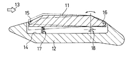
図1は、本発明の実施の一形態の断面構成を示す。すり板11は、舟体12上に支持され、車両の進行に伴って受ける風としての送風方向13に対し、集電舟全体として翼型プロフィールを形成して低騒音化が図られる。すり板11は、舟体12の上方に設ける溝14内に収納され、前縁15と後縁16との間で、舟体12の上面から突出し、全体としての翼型プロフィールの上面の中央部分を構成する。前縁15側にはばね17が設けられ、後縁16側には球面滑り軸受18が設けられる。すり板11の球面軸受18は、舟体12の長手方向ですり板11の両端付近でかつ、後端側ですり板11を前後左右に揺動可能に支持するように設置していることから、球面軸受18付近、すなわち舟体12の長手方向の端部付近のすり板部では、すり板11は上下方向には拘束され、ピッチング方向の自由度とすり板11に可撓性を与えていることから、局部的なローリング変形をする。よって球面軸受18付近では、すり板11は2点鎖線で示すように前縁15側が後縁16側に比較して大きく変位可能である。後縁16側では、翼型プロフィール全体としての上面と下面との距離の変化が小さく、したがってその中心線と翼の前縁および後縁間の翼弦との間の距離であるキャンバの最大量付近での変化も小さい。揚力に影響を与えるキャンバの変化が小さいので、すり板11の変位による集電舟全体としての揚力への影響は小さい。
【0011】
すり板11の幅方向について、上下方向の可撓性による弾性よりも、上下方向に押上げているばね17のばね定数を小さく設定しているので、舟体12の長手方向の中央部付近でも、すり板11の可撓性によって上下に変位は加わるが、長手方向端部の影響を受けて、前縁15側が後縁16側に比較して大きく変位することとなり、すり板11の舟体長手方向端部で考察した結果と同様に、キャンバの最大値付近の変化量が少なくなり、よって揚力特性の変化量を少なくすることが可能である。
【0012】
図2および図3は、集電舟全体としての平面図および正面図をそれぞれ示す。一対の球面軸受18は、すり板11の後縁16側の長手方向両端付近に設けられる。ばね17は、すり板11の前縁15の中央付近に設けられる。舟体12の幅方向の両端には、他の架線に移る場合に案内するためのホーン19が設けられる。
【0013】
図4は、図3の中央付近の断面構造を示す。すり板11には可撓性を持たせ、長手方向の両端付近を球面軸受18によって支持されているので、2点鎖線で示すように中央部を撓ませて、架線に対する追従性を高めることができる。
【0014】
図5は、本実施形態による舟体11を備えるパンタグラフを正面から見た構成を示す。舟体11は、間隔をおいて設けられる一対のポール20によって支持され、全体的に「π」型の形状に構成される。ポール20の基端側には、揺動軸21が設けられ、揺動軸21を中心としてポール20は揺動変位可能である。揺動軸21は、鉄道車両の屋根に碍子を介して固定される台枠22で支持される。
【0015】
図6は、本実施形態に用いることができる球面軸受18の一例について基本的構成を示す。インナーレース31は、アウターレース32に対して自由に回転変位を行うことができる。インナーレース31は、軸30を介してすり板に固定され、アウターレース32は、舟体12に固定される。軸30とすり板との固定は、ねじなどを介して着脱可能とし、摩耗したすり板の交換を容易に可能とすることが好ましい。
【0016】
図7は、図5に示すパンタグラフを右側方から見た状態を示す。ポール20の先端と舟体12との間には、舟体12の姿勢を保つ支持装置40が設けられる。支持装置40は、支軸41によって、ポール20の先端にピン結合される。台枠22および台枠カバー23内には、ポール20の基端がピン結合される揺動軸21回りに揺動変位させ、傾斜角度θ1を変化させて舟体12を上昇または下降させるための昇降装置42が収納される。
【0017】
架線高さが変化すると舟体12の高さもこれに追従して変化する。この際、舟体12で発生する揚力および抗力が一定であっても、傾斜角θ1が変化すると揺動軸21回りの回転モーメントに対する寄与が変化し、架線への押付け力が変化する。押付け力を一定にするために、補助リンク43を用いて、支持装置40の姿勢を変化させ、舟体11の迎角を調整する。ポール20は中空に形成され、補助リンク43を内部に収納する。補助リンク43の上端側は、支持装置40の上端付近に関節点44によってピン結合される。補助リンク43の下端側は、台枠22に固定された腕46端部の関節点45によってピン結合される。揺動軸21、支軸41、関節点44,45の相互間の部分は、非平行四辺形リンクを形成する。この非平行四辺形リンクによって、すり板11の上面のレール面47からの高さである作用高さHがΔH1だけ増加するときには、舟体12の迎角がα1だけ増加し、作用高さHがΔH2だけ減少するときには、迎角がα2だけ減少するような作用が可能である。
【0018】
図8は、図1の実施形態のすり板11および舟体12を総合した断面形状による翼型プロフィールを示す。この翼型プロフィールは、翼型前縁51と翼型後縁52との間の長さをx0、中央付近で翼型上面53が対称である部分の長さをx1として構成される。翼型下面54が対称である部分の長さは、中央付近で翼型上面53が最も高くなっている部分の長さx2の前方にx3、後方にx4だけ付加した範囲である。翼型前縁51は、翼型下面54からy1だけ上方で、半径r1の円周上にある。翼型後縁52は、半径r2の円周上にあり、その近傍には、翼型下端55が、翼型下面54の延長上から尻下がり量Aだけ下方側に下がった位置となるような形状をとる。翼厚さの中心線56に対して、翼型前縁51および翼型後縁52間を結ぶ翼弦57からの高さであるキャンバの最大量はy2となる。
【0019】
以上の実施形態では、π型パンタグラフの舟体によるすり板支持構造を示しているけれども、Z型や、菱型など、他のパンタグラフの形状であっても同様に本発明を適用することができる。
【0020】
【発明の効果】
以上のように本発明によれば、すり板の前縁側をばね手段によって上方にばね付勢し、すり板の後縁側を長手方向両端付近で球面軸受から成る一対の支持手段によって支持するので、翼型プロフィールとしての断面形状を有する舟体の迎角を変化させて、舟体に発生する揚力を調整しても、すり板は架線と良好な線接触状態を保ち、かつ架線との間の押付け力変化も小さくすることができる。
【図面の簡単な説明】
【図1】本発明の実施の一形態の側断面図である。
【図2】図1の実施形態の平面図である。
【図3】図1の実施形態の正面図である。
【図4】図1の実施形態の部分的な正面断面図である。
【図5】図1の実施形態の舟体を用いるπ型パンタグラフの正面図である。
【図6】図1の実施形態に用いる球面軸受の一例について原理的構成を部分的に切欠いて示す斜視図である。
【図7】図5に示すπ型パンタグラフの右側面図である。
【図8】図1の実施形態のすり板および舟体を総合した翼型プロフィール図である。
【図9】従来からの舟体の簡略化した右側面図である。
【図10】図9の舟体にすり板を取付ける状態を示す部分的な断面図である。
【符号の説明】
11 すり板
12 舟体
14 溝
15 すり板前縁
16 すり板後縁
17 ばね
18 球面軸受
20 ポール
21 揺動軸
30 軸
31 インナーレース
32 アウターレース
40 支持装置
41 支軸
42 昇降装置
43 補助リンク
44,45 関節点[0001]
BACKGROUND OF THE INVENTION
The present invention relates to a structure for supporting a collecting plate in a pantograph for a railway vehicle with a hull, and in particular, a pantograph hull plate support structure in the case of using a wing profile for reducing noise as a hull. About.
[0002]
[Prior art]
Conventionally, a pantograph has been widely used as a device for collecting electricity from an overhead line installed above a vehicle. FIG. 9 and FIG. 10 show a simplified configuration for collecting a rhombus pantograph. The sliding plate 1 that slides directly on the overhead wire and collects current is detachably attached to the hull. The
[0003]
The sliding plate 1 performs a current collecting action while always in contact with the overhead wire. It is inevitable that the overhead wire and the sliding plate 1 are worn by such sliding. Since it is necessary to construct the overhead line along a railroad track for a long distance, it is necessary to avoid wear and tear as much as possible. For this reason, it is necessary that the sliding plate 1 side takes on as much wear as possible and can be easily replaced after wear. As a prior art for fixing the sliding plate and the boat body with screws, there is also a configuration disclosed in, for example, Japanese Patent Laid-Open No. 6-86405. In this prior art, a boat body is formed of a high-strength material made of fiber reinforced plastic, an internal screw is formed on a current collecting ground plate, and is directly fixed with bolts from the boat body side.
[0004]
[Problems to be solved by the invention]
In the conventional pantograph, as described above, a sliding plate is directly attached to the hull, and fluctuations in the relative height of the overhead line as the vehicle travels are deformed and absorbed by the hull side.
[0005]
However, in pantographs for high-speed vehicles represented by the Shinkansen, it has become difficult to meet environmental standards for noise as the vehicle speed increases, and it is possible to reduce noise by using the hull as a wing shape. It is being considered. This is because the airfoil is streamlined so that the flow is hardly disturbed even with a high-speed air flow, and the level of generated noise can be reduced. However, along with the wing shape, lift force that pushes up the boat body is likely to occur, and the pressing force between the sliding plate and the overhead wire is likely to increase. When the pressing force between the overhead wire and the sliding plate increases more than necessary, the wear on the sliding surface becomes severe, and not only the life of the sliding plate and the overhead wire is shortened, but also there is a risk of cutting the overhead wire.
[0006]
In order to maintain the pressing force between the sliding plate and the overhead wire within an appropriate range even when lift is generated from the wing-shaped cross-section, it is conceivable to change the angle of attack of the hull. When the angle of attack of the hull is changed, the angle of the sliding plate fixed to the upper surface of the hull also changes, and there is a possibility that the contact between the sliding plate and the overhead line can be made only at “points”. With local contact, the current density increases and heat is generated, and the possibility of damage to the sliding plate and overhead wire due to sparks increases. In addition, local wear progresses, leading to a shortened life of the sliding plate and the overhead wire. Although it is conceivable to change the posture in the pitching direction of the sliding plate around the center of the sliding plate so that the overhead wire and line contact are possible, if the wing profile of the entire hull including the sliding plate is changed, Since the lift characteristics of the hull change due to the profile change, the lift adjusted by changing the angle of attack tends to return to the original value again.
[0007]
SUMMARY OF THE INVENTION An object of the present invention is to provide a pantograph hull sliding plate support structure capable of keeping a sliding plate in line contact with an overhead line without affecting the lift adjusted by changing the angle of attack of the hull. There is to do.
[0008]
[Means for Solving the Problems]
The present invention is a structure for supporting a current collecting sliding plate on a boat body having an airfoil cross section and an angle of attack variably supported.
A pair of support means consisting of spherical bearings that support the sliding plate in the vicinity of both ends in the longitudinal direction and the rear edge side in the vicinity of both ends in the longitudinal direction of the hull so as to be swingable back and forth and left and right;
The leading edge side than the supporting means of the sliding plate, a sliding plate support structure of the pantograph collector head, characterized in that it comprises spring means for spring-biased upwardly.
The lift and lift characteristics of a hull with an airfoil section are mainly affected by the ratio of camber amount to chord and angle of attack.
According to the present invention, when adjusting the lift by changing the angle of attack of the hull of the airfoil cross section, the sliding board follows the overhead line and remains almost horizontal. Pitching direction relative displacement between the hull and the sliding plate is possible while maintaining the maximum value of the camber including the hull with respect to the change in angle of attack, so even if the sliding plate is displaced in the pitching direction. It is possible to obtain a sliding plate support method that is less affected by the lift characteristics of the sliding plate and obtains a predetermined lifting force according to the change in the angle of attack, and swings the sliding plate near the both ends in the width direction of the sliding plate and back and forth, left and right. It is movably supported by a pair of support means.
Spring means for urging upward is provided on the front edge side of the sliding plate.
The sliding plate is supported so as to be swingable back and forth and right and left at the rear end sides in the width direction, and is configured so that the central portion is flexible. It is possible to follow up and down fluctuations and pitching fluctuations. The spring means can improve the followability of the sliding plate. Since the support point of the sliding plate is near the trailing edge, even if the leading edge moves up and down by the spring means, the change in the overall airfoil shape near the trailing edge is small and affects the lift as the sliding plate. The change in the vicinity of the maximum value of the camber can be reduced, and the fluctuation of the pressing force due to the change in the attack angle can be suppressed while maintaining the line contact state between the overhead wire and the sliding plate.
[0009]
In addition, since the support means is provided with a spherical bearing, the followability of the sliding plate to the overhead wire can be improved, and a reliable current collecting action with the overhead wire can be realized.
[0010]
DETAILED DESCRIPTION OF THE INVENTION
FIG. 1 shows a cross-sectional configuration of an embodiment of the present invention. The
[0011]
About width Direction of sliding
[0012]
2 and 3 show a plan view and a front view of the current collector boat as a whole. The pair of
[0013]
FIG. 4 shows a cross-sectional structure near the center of FIG. Since the sliding
[0014]
FIG. 5 shows a configuration of the pantograph provided with the
[0015]
FIG. 6 shows a basic configuration of an example of the
[0016]
FIG. 7 shows a state where the pantograph shown in FIG. 5 is viewed from the right side. A
[0017]
When the overhead line height changes, the height of the
[0018]
FIG. 8 shows an airfoil profile having a cross-sectional shape in which the sliding
[0019]
In the above embodiment, the sliding plate support structure by the π-type pantograph boat is shown, but the present invention can be similarly applied to other pantograph shapes such as a Z shape and a diamond shape. .
[0020]
【The invention's effect】
As described above, according to the present invention, the leading edge side of the sliding plate is spring-biased upward by the spring means, and the trailing edge side of the sliding plate is supported by the pair of supporting means composed of spherical bearings near both ends in the longitudinal direction. Even if the angle of attack of the hull with a cross-sectional shape as an airfoil profile is changed and the lift generated in the hull is adjusted, the sliding plate maintains good line contact with the overhead wire, and between the overhead wire The pressing force change can also be reduced.
[Brief description of the drawings]
FIG. 1 is a side sectional view of an embodiment of the present invention.
FIG. 2 is a plan view of the embodiment of FIG.
FIG. 3 is a front view of the embodiment of FIG.
FIG. 4 is a partial front cross-sectional view of the embodiment of FIG.
FIG. 5 is a front view of a π-type pantograph using the boat body of the embodiment of FIG.
FIG. 6 is a perspective view partially showing a principle configuration of an example of a spherical bearing used in the embodiment of FIG. 1;
7 is a right side view of the π-type pantograph shown in FIG.
FIG. 8 is an airfoil profile diagram in which the sliding plate and the hull of the embodiment of FIG. 1 are integrated.
FIG. 9 is a simplified right side view of a conventional hull.
10 is a partial cross-sectional view showing a state in which a sliding plate is attached to the boat body of FIG. 9. FIG.
[Explanation of symbols]
11 Sliding
Claims (1)
前記すり板の長手方向両端付近でかつ後縁側を舟体の長手方向両端付近で、前後左右に揺動可能に支持する球面軸受から成る一対の支持手段と、
前記すり板の前記支持手段よりも前縁側を、上方にばね付勢するばね手段とを含むことを特徴とするパンタグラフ舟体のすり板支持構造。A structure that has a wing-shaped cross section and supports a current collecting slip plate on a hull whose angle of attack is variably supported,
A pair of support means consisting of spherical bearings that support the sliding plate in the vicinity of both ends in the longitudinal direction and the rear edge side in the vicinity of both ends in the longitudinal direction of the hull so as to be swingable back and forth and left and right;
Sliding plate support structure of the pantograph collector head, characterized in that it comprises an edge before said support means of said sliding plate, and a spring means for spring-biased upwardly.
Priority Applications (1)
| Application Number | Priority Date | Filing Date | Title |
|---|---|---|---|
| JP15719896A JP3902811B2 (en) | 1996-06-18 | 1996-06-18 | Pantograph boat support structure |
Applications Claiming Priority (1)
| Application Number | Priority Date | Filing Date | Title |
|---|---|---|---|
| JP15719896A JP3902811B2 (en) | 1996-06-18 | 1996-06-18 | Pantograph boat support structure |
Publications (2)
| Publication Number | Publication Date |
|---|---|
| JPH1014006A JPH1014006A (en) | 1998-01-16 |
| JP3902811B2 true JP3902811B2 (en) | 2007-04-11 |
Family
ID=15644354
Family Applications (1)
| Application Number | Title | Priority Date | Filing Date |
|---|---|---|---|
| JP15719896A Expired - Lifetime JP3902811B2 (en) | 1996-06-18 | 1996-06-18 | Pantograph boat support structure |
Country Status (1)
| Country | Link |
|---|---|
| JP (1) | JP3902811B2 (en) |
Families Citing this family (1)
| Publication number | Priority date | Publication date | Assignee | Title |
|---|---|---|---|---|
| JP2019054689A (en) * | 2017-09-19 | 2019-04-04 | 東洋電機製造株式会社 | Pantagraph for railway vehicle |
-
1996
- 1996-06-18 JP JP15719896A patent/JP3902811B2/en not_active Expired - Lifetime
Also Published As
| Publication number | Publication date |
|---|---|
| JPH1014006A (en) | 1998-01-16 |
Similar Documents
| Publication | Publication Date | Title |
|---|---|---|
| EP3498519B1 (en) | Train current collecting device | |
| US6675433B1 (en) | Beam blade wiper assembly having improved wind lift characteristics | |
| JP3902811B2 (en) | Pantograph boat support structure | |
| JP3342779B2 (en) | Mounting structure of wind receiver in wiper device | |
| JP2002532041A (en) | Current collector for electrically operated rail vehicles | |
| JP3104199B2 (en) | Collector boat for current collectors for railway vehicles | |
| JPH05328512A (en) | Lift control blade for single arm type pantograph | |
| JP3448430B2 (en) | Pantograph and hull | |
| JP6215036B2 (en) | Pantograph vertex cover and pantograph having the vertex cover | |
| JP3530222B2 (en) | Hull support mechanism for current collectors for railway vehicles | |
| EP4008596B1 (en) | Car for railway vehicle with roof fairing | |
| JP2916759B2 (en) | Windproof cover for current collector | |
| JP3924660B2 (en) | Lift adjustment method for single arm pantograph | |
| CN218453369U (en) | Coupling mechanism, connection control system and rail vehicle | |
| JP3266777B2 (en) | Pantograph push-up force control method and apparatus | |
| JP2817126B2 (en) | Collector boat for current collectors for railway vehicles | |
| JP4641897B2 (en) | Arm pantograph top cover | |
| RU2203194C1 (en) | Transportation system high speed module | |
| JP2675168B2 (en) | Vehicle | |
| JP3372139B2 (en) | Single arm type pantograph | |
| RU2201368C1 (en) | High-speed module of transportation system | |
| JP2022091528A (en) | Collector head | |
| RU2201369C1 (en) | High-speed module of transportation system | |
| RU2203195C1 (en) | Transportation system high speed module | |
| JP2020182289A (en) | Collector head and power collector shoe device |
Legal Events
| Date | Code | Title | Description |
|---|---|---|---|
| A131 | Notification of reasons for refusal |
Free format text: JAPANESE INTERMEDIATE CODE: A131 Effective date: 20060912 |
|
| A521 | Written amendment |
Free format text: JAPANESE INTERMEDIATE CODE: A523 Effective date: 20061113 |
|
| TRDD | Decision of grant or rejection written | ||
| A01 | Written decision to grant a patent or to grant a registration (utility model) |
Free format text: JAPANESE INTERMEDIATE CODE: A01 Effective date: 20061226 |
|
| A61 | First payment of annual fees (during grant procedure) |
Free format text: JAPANESE INTERMEDIATE CODE: A61 Effective date: 20070105 |
|
| R150 | Certificate of patent or registration of utility model |
Free format text: JAPANESE INTERMEDIATE CODE: R150 |
|
| FPAY | Renewal fee payment (event date is renewal date of database) |
Free format text: PAYMENT UNTIL: 20100112 Year of fee payment: 3 |
|
| FPAY | Renewal fee payment (event date is renewal date of database) |
Free format text: PAYMENT UNTIL: 20110112 Year of fee payment: 4 |
|
| FPAY | Renewal fee payment (event date is renewal date of database) |
Free format text: PAYMENT UNTIL: 20120112 Year of fee payment: 5 |
|
| FPAY | Renewal fee payment (event date is renewal date of database) |
Free format text: PAYMENT UNTIL: 20120112 Year of fee payment: 5 |
|
| FPAY | Renewal fee payment (event date is renewal date of database) |
Free format text: PAYMENT UNTIL: 20130112 Year of fee payment: 6 |
|
| FPAY | Renewal fee payment (event date is renewal date of database) |
Free format text: PAYMENT UNTIL: 20130112 Year of fee payment: 6 |
|
| FPAY | Renewal fee payment (event date is renewal date of database) |
Free format text: PAYMENT UNTIL: 20140112 Year of fee payment: 7 |
|
| FPAY | Renewal fee payment (event date is renewal date of database) |
Free format text: PAYMENT UNTIL: 20150112 Year of fee payment: 8 |
|
| R250 | Receipt of annual fees |
Free format text: JAPANESE INTERMEDIATE CODE: R250 |
|
| R250 | Receipt of annual fees |
Free format text: JAPANESE INTERMEDIATE CODE: R250 |
|
| EXPY | Cancellation because of completion of term |