JP3901739B2 - Removal of cell products from water - Google Patents
Removal of cell products from water Download PDFInfo
- Publication number
- JP3901739B2 JP3901739B2 JP54970598A JP54970598A JP3901739B2 JP 3901739 B2 JP3901739 B2 JP 3901739B2 JP 54970598 A JP54970598 A JP 54970598A JP 54970598 A JP54970598 A JP 54970598A JP 3901739 B2 JP3901739 B2 JP 3901739B2
- Authority
- JP
- Japan
- Prior art keywords
- frequency
- pipe
- conduit
- output
- oscillator
- Prior art date
- Legal status (The legal status is an assumption and is not a legal conclusion. Google has not performed a legal analysis and makes no representation as to the accuracy of the status listed.)
- Expired - Fee Related
Links
Images


Classifications
-
- C—CHEMISTRY; METALLURGY
- C02—TREATMENT OF WATER, WASTE WATER, SEWAGE, OR SLUDGE
- C02F—TREATMENT OF WATER, WASTE WATER, SEWAGE, OR SLUDGE
- C02F1/00—Treatment of water, waste water, or sewage
- C02F1/48—Treatment of water, waste water, or sewage with magnetic or electric fields
-
- C—CHEMISTRY; METALLURGY
- C02—TREATMENT OF WATER, WASTE WATER, SEWAGE, OR SLUDGE
- C02F—TREATMENT OF WATER, WASTE WATER, SEWAGE, OR SLUDGE
- C02F2201/00—Apparatus for treatment of water, waste water or sewage
- C02F2201/48—Devices for applying magnetic or electric fields
- C02F2201/483—Devices for applying magnetic or electric fields using coils
-
- C—CHEMISTRY; METALLURGY
- C02—TREATMENT OF WATER, WASTE WATER, SEWAGE, OR SLUDGE
- C02F—TREATMENT OF WATER, WASTE WATER, SEWAGE, OR SLUDGE
- C02F2303/00—Specific treatment goals
- C02F2303/04—Disinfection
Landscapes
- Organic Chemistry (AREA)
- Life Sciences & Earth Sciences (AREA)
- Engineering & Computer Science (AREA)
- Environmental & Geological Engineering (AREA)
- Water Supply & Treatment (AREA)
- Chemical & Material Sciences (AREA)
- Hydrology & Water Resources (AREA)
- Water Treatment By Electricity Or Magnetism (AREA)
- Purification Treatments By Anaerobic Or Anaerobic And Aerobic Bacteria Or Animals (AREA)
- Cosmetics (AREA)
- Investigating Or Analyzing Materials By The Use Of Magnetic Means (AREA)
- Seasonings (AREA)
- Water Treatment By Sorption (AREA)
- Measuring Or Testing Involving Enzymes Or Micro-Organisms (AREA)
Abstract
Description
技術分野
本発明は、水泳プール、貯水池、ダムなどの水域を浄化するための方法および装置に関する。特に、水からのバクテリア、微生物、その他の細胞発生物の除去に関する。
背景技術
水泳プール、取水域などの大水域には、(その水域で泳いだり水浴びにより、あるいは、その水を飲むことにより)人と連続的に接するべき水があり、浄化が望まれる。砂などの濾過媒体と協働する種々のフィルターを用いて粒子その他の固形片を除去することができるが、有害なバクテリアその他の微生物発生物の除去はより困難である。このようなバクテリアなどは、通常は、水域に適切な化学物質を定期的に投入することによって、除去される。たとえば、一般に、次亜塩素酸ナトリウムがプールに加えられ、水中に溶解した塩素成分が、水中に存在するバクテリアなどの致死量レベルになるように維持される。飲料水基準にまで水域を浄化しなければならない公営事業において、広い範囲の化学物質を水に加えて浄化することができる。
これらの現存の方法には多くの欠点がある。水泳プールは、水を浄化するのに必要な塩素成分がプール内の人の目を刺激することがよくあるので、処理後一定期間が経過しなければ使用することができない。飲料水の処理においては、水源への慎重な化学物質の添加自体が有害であるとの公衆による心配が増大している。例えば、処理された水は、人によっては、アレルギー反応を引き起こす可能性がある。したがって、ますます多くの消費者にとって、使用又は消費する前に、供給された水を濾過あるいはさらに処理する必要がある。もちろん、化学物質の使用および/又は供給された水のさらなる処理は、すべて、共同体により使用されるために受け入れ可能な水の供給を維持する財政コストを加える。
したがって、本発明の全般的な目的は、1又は2以上の上記欠点を克服し、少なくとも改良することである。
発明の開示
本発明によれば、水域からバクテリア、微生物、その他の細胞発生物を除去する方法を提供する。該方法は、
その中を水が通るように水域に通じることができるパイプ又は同様の導管の一区画に電磁場を適用することを含み、該電磁場は上記水から上記バクテリア、微生物、その他の細胞発生物を抑制又は除去するのに十分な一つの周波数又はある範囲の周波数を有する。
上記パイプの一区画に対する電磁場の適用は、上記パイプ又は導管の壁に配置された1又は2以上の要素を磁化することによって達成できる。
4個の等間隔に配置された要素を、上記パイプ又は導管に配置することができる。
上記要素は、フェライト材料の細長い片とすることが可能である。
上記フェライト材料は、マンガン亜鉛(manganise-zinc)とすることが可能である。
上記要素は、磁化可能なコイルとすることが可能である。
本発明のさらなる観点によれば、水域からバクテリア、微生物、その他の細胞発生物を除去する装置を提供する。該装置は、
水域に通じることができるパイプの一区画のまわりに配置されるように構成された磁化可能な要素と、
該磁化可能な要素に信号を与え、上記パイプ内に電磁場を形成する手段とを備え、該電磁場は上記水から上記バクテリア、微生物、その他の細胞発生物を抑制又は除去するのに十分な一つの周波数又はある範囲の周波数を有する。
上記磁化可能な要素は、パイプの一区画の壁に配置された1又は2以上のフェライト要素を備えることができる。
上記1又は2以上のフェライト要素は、マンガン亜鉛要素とすることが可能である。
上記磁化可能な要素は、上記パイプ又は導管に電磁場を適用するためのコイルとすることが可能であって、該コイルは、上記パイプ又は導管のまわりに同軸に配置された塩化ビニル樹脂(PVC)その他の非鉄巻型のまわりに巻かれている。
電磁場を発生させるために、上記磁化可能な要素に交流電圧を印加することが可能である
その電圧は、交流5ボルトとすることが可能である。
上記磁化可能な要素に加えられる電圧の周波数は、2KHz〜7KHzの範囲内のある範囲の周波数を掃引するために、変化することができる。
上記磁化可能な要素に加えられる信号は、正側の方形波とそれに続く負側のスパイクであって一つの可変周波数を有する形である。
信号を発生させる手段は、第1および第2の方形波発振器を備え、上記第2の発振器の出力は第1の発振器の出力により周波数を変調されることが可能である。
信号発生手段は第3の方形波発振器も備えることができる。上記第2の発振器の出力は上記第3の方形波発振器の出力を周波数変調するために用いられる。
増幅器手段は、上記第3の方形波発振器の出力を増幅するために使用可能であり、該増幅器手段の出力は、所望の信号波形を決定するため容量手段を経て磁化可能要素に接続されるように構成される。
【図面の簡単な説明】
本発明をより容易に理解し実際の効果を与えるため、本発明の好ましい実施例を示す以下の図面が参照される。
図1は、本発明により構成された装置の全般的性質を示す。
図2は、信号を発生させ、その信号をその中を水が通るパイプに与えるための回路の電気回路図である。
図3は、本発明を水泳プールに適用した図である。
図4は、信号を発生させて、その中を水が通るパイプに信号を与える回路の変形例の電気回路図である。
図5は、本発明による装置が取り付けられている、水泳プール濾過システムからのパイプの一区画の図である。
図6は、本発明のプローブが配置されている、水泳プール設備のパイプの断面図である。
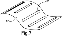
図7は、本発明の別の観点に従うパイプバンドの斜視図である。
発明を実施するための最良の形態
まず、図1を参照すると、プラスチック材料、好ましくはポリ塩化ビニル樹脂(PVC)のような、非磁性、非鉄材料から作られた巻型12を備える装置10が図示されている。巻型12のまわりには、ワイヤが何周も巻かれ、コイル13を形成している。このコイル13は、信号発生器14から信号を受けるように接続されている。
巻型12は、好ましくは、直径40mmであり、その上に3層の0.315mm絶縁銅ワイヤが巻かれ、巻型12に沿って約170mm延在する。巻型は、ワイヤの巻きを囲むために外側ケーシングを備えるてもよく、あるいは、ワイヤの層に収縮スリーブを備えてもよい。
コイルは、信号発生器に接続されるようになっている。信号発生器は、回路の作動を示す発光ダイオード(LED)の形のインジケータ16と、装置10への電源供給を示す発光ダイオード(LED)の形のインジケータ17とを備えるケーシング15内に収納される。ケーシング15内には、信号発生回路19および協働する電源20のコンポーネントを搭載する回路基板18が取り付けられている。
電源20は、ブリッジ整流器B1とコンデンサC1を含む。これらは、AC電源21に接続され、脈動DC電圧を整流器B1の出力で供給する。その周波数は、本実施例では100Hzである。次に、その電圧はキャパシタC2に印加され、フィルタをかけ平滑化して、DC電圧を供給する。この平滑化されたDC電圧は、次に、調整器Reg1に印加される。調整器Reg1は、この場合、12ボルトの固定されたDC電圧を出力し、コンデンサC3と結合して調整された12ボルト電源を供給する。抵抗R2は、外部に取り付けられ回路に電源供給されていることを示すLED16に、ブリッジB1からの電圧出力を与える。抵抗R2は、LED16に流れる電流を制限する。
抵抗R4、ツェナーダイオードZ1およびキャパシタC4は、さらなる電源供給(VCC)、好ましくは5ボルトDC電源を形成し、信号発生回路19に印加される。代わりに、さらに別の調整器を用い、回路19に対する供給のために調整された出力を供給してもよい。
信号発生回路19は、第一に、カッド・アンド・ゲート・シュミット・トリガー回路19を形成する。この例では、U1:A、U1:B、U1:C、U1:Dで示した4つの分離したゲートを有するタイプ4093CMOS集回路U1を備える。
ゲートU1:Cは、抵抗R13およびキャパシタC11とともに、発振器22を形成する。その周波数は、抵抗R13およびキャパシタC11により決定され、10Hzである。ゲートU1:Dは、抵抗R16およびキャパシタC13とともに発振器23を形成し、その標準発振周波数は7Hzである。発振器22および23の両方は、正側の方形波出力を設定する。発振器23の出力は、抵抗R13およびR14とキャパシタC12を介して発振器22の入力に接続されている。キャパシタ12は、発振器23の出力により、充電、放電を行い、発振器22の入力に、調整信号を与える。したがって、発振器22の出力は、模式的に図示した24のような形状の調整された負側の方形波であり、周波数は発振器23の出力により決定されたように変化する。この出力信号の平均周波数は、3.8kHzである。
この出力信号は、抵抗R12を経て、トランジスタQ4のベースに与えられ、周波数が変わる信号24は、トランジスタQ4を変化する周波数でオン・オフ切り換えるために働く。R12の目的は、トランジスタQ4のベースへの電流を制限することである。
ゲートU1:Bは、抵抗R10とキャパシタC9およびC10に接続され、さらに別の発振器25を形成する。その出力は、標準では、正側の方形波である。発振器22および23のように、この発振器の周波数は、その協働する抵抗およびキャパシタ、この場合、抵抗R10およびキャパシタC9およびC10の値によって制御される。発振器25は、標準的には、2.6kHzの周波数で作動するであろう。キャパシタC9およびC10は直列に接続され、同じ値であり、直列のキャパシタC9およびC10のキャパシタンスはそれぞれのキャパシタのキャパシタンスの合計の半分である。この発振器25は、トランジスタQ4を経て与えられる発振器22の出力信号24によって変調される。キャパシタC9およびC10は、トランジスタQ4のコレクタに接続され、分路のオン・オフ切り換え時に、出力信号24の可変周波数により決定された周波数でキャパシタC9をグランドに接続する。このスイッチングの効果は、トランジスタQ4がオンに切り替わるごとに、直列のキャパシタC9およびC10のキャパシタンスを2倍にすることである。したがって、これは、発振器25の出力において出力周波数を半分にする。
発振器25の出力は、抵抗R9とキャパシテイタC8により形成されるR−C回路を経て、信号を増幅してその増幅信号をキャパシタC6の正極に与えるトランジスタQ3およびQ2のダーリントンペアに接続されている。キャパシタC6は、より陰極板でDC電圧を絶縁し、その信号をコネクタJ2を経てコイル13に与える。コイル13が接続されると、信号はコイル13を通り抵抗R7を経てグランドに戻る。26で示したコイル13に与えられた信号は、正側の方形波と、指数曲線でゼロに戻る負側のスパイクとからなる。
集積回路U1の第4ゲートU1:Aは、コイル13が作動中であることを示すための検出器として用いられる。抵抗R5およびR11は、電圧VCCに接続されゲートU1:Aに入力を与える分圧器を形成する。ゲートU1:Aの入力も、キャパシタC5および抵抗R6を経て、コイル13に接続されている。
コイル13が接続されず、あるいは作動していないときには、分圧器R5およびR11によりゲートU1:Aの入力に与えられる電圧により、ゲートU1:Aの出力はローになる。コイル13が作動しているときには、ゲートU1:Aへの入力電圧は、この電圧をR6に接続するキャパシタC5の交流により、低くされる。入力電圧がシュミットトリガーU1:Aのトリップポイントより低くなると、ゲートU1:Aの出力は高くなり、したがって、抵抗R3に電圧が与えられる。この電圧は、トランジスタQ1のベースに接続され、トランジスタQ1への電流を制限する働きをする。この電流が制限されると、電圧はトランジスタQ1と電流制限抵抗R1とに与えられ、したがって、コイル13が接続されて作動中であるとき、照明される。
コイル13が取り外され、あるいは作動中でないときには、ベース電流がないので、トランジスタQ1はオフに切り換えられ、LED17は消える。好ましくは、LED16およびLED17の両方はコネクタJ3を通って外部に接続される。
コイルコネクタ、すなわちジャックJ2への出力は、ゲートU1:CおよびU1:Dにより発生させられる無秩序なある範囲の周波数を含む。上述のように、U1:CおよびU1:Dの両者は、分離した発振器として接続され、U1:Dの出力は、U1:Cの入力に与えられる。ゲートU1:Cを含む発振器22は、ゲートU1:Dを含む発振回路23より実質的に高い周波数を与える。したがって、互いに接続されていないなら、U1:Cの発振器22は約10Hzの周波数を与え、U1:Dのそれは約7Hzである。複合回路は、通常、1kHz〜7kHzの範囲の周波数の掃引を発生させる。
しかし、本発明の範囲内において、コイルに与えるための上記範囲を超えた単一周波数出力や一定範囲の周波数を与える発振回路を提供する。適切な周波数は、細胞発生物の特性、および/又は、パイプを通る水量に応じて、選択される。
図3に示したように、本発明の装置は、水泳プールを表す設備27に適切に適用してよい。コイル13を携える巻型12は、パイプのまわりに配置され、プール内で水面より下に配置される。ハウジング15に収納された信号発生器14は、任意の適宜位置に取り付けられ、ワイヤ32を介してコイル13に接続される。
図4に関しては、本発明のさらなる観点にしたがって、シングルシップマイクロコントローラ22から、信号がまず生成される。この実施例ではタイプPIC16C73A マイクロコントローラを備える。4.00MhzクリスタルX1および2個の15pFキャパシタC17およびC18が、マイクロコントローラ用ベース周波数発振器を形成する。C14および15は、マイクロコントローラへの電源供給を安定化するバイパスキャパシテイタとして働く。DS1233−10リセットユニットは、マイクロコンピュータがパワーオンのたびにうまくスタートすることを確実にする。
マイクロコントローラは、7kHzで変調された10Hzで内部方形波信号を発生させ、平均周波数3.8kHzの信号を作る。この信号は、第3の発振器の周波数を変更するために使用される。第3の発振器は、標準的には、2.6kHzの周波数で作動する。この第3の発振器に与えられる信号の効果は、信号が高くなるときはいつも、第3の発振器の周波数を有し、信号が低くなるときは、第3の発振器の周波数をその標準周波数に戻す。この第3の発振器RC0(CDRV)の出力は、抵抗R9およびキャパシタC8により形成されるR0−C回路を経て、トランジスタQ3およびQ2のダーリントンペアに与えられ、信号をキャパシタC6の正極に増幅する。キャパシタC6は、より陰極でDC電圧を絶縁し、コネクタj2を経てコイル13に信号を与える。コイル13が接続されると、信号はコイル13を通り、抵抗R7を経てグランドに戻る。26で示したコイル13に与えられる信号は、正側の方形波と、指数曲線でゼロに戻る負側のスパイクとからなる。抵抗R5およびR11は、電圧VCCに接続されマイクロコントローラにRB0(CFB)で入力を与える分圧器を形成する。この入力もキャパシタC5および抵抗R6を経てコイル13に接続され、コイル13が作動していることを示す検出器として用いられる。
コイル13が接続されず、あるいは作動していないとき、電圧分圧器R5およびR11によりマイクロコントローラの入力に与えられた電圧は低く、マイクロコントローラはLED17を消す。もし、コイル13が接続され、かつ作動しているならば、入力電圧は高くなり、マイクロコントローラはLEDを点灯する。したがって、LED17は、コイル作動インジケータとして働く。作動用のベース周波数は、この場合PIC24CO4APである直列のEEPROM(Electrically Erasable Programmable Read Only Memory)U5に記憶される。これらの周波数は、2つの押しボタンPB1およびPB2とディスプレイDSP1およびDSP2を経て調整することにより、特定の適用に適合するように変更してもよい。これらの押しボタンとディスプレイは、好ましくは、メインシステムボードに組み込み可能な追加ボード上に配置し、それにより、そうする権限を与えられたそれらだけに対して周波数を変更する可能性を制限する。
トランジスタQ1およびQ5は数字の表示を多重送信するために役に立つ。数字表示は、マイクロコントローラがQ1をオンしQ5をオフすることによってのみ、DSP1に与えられてよい。DSP2に数字を表示するために、マイクロコントローラはQ5をオンし、Q1をオフする。この処理を1秒あたり約60回切り換えることによって、人の目は、繰り返しオンとオフが切り換わる表示により明減する量を検出することができないであろう。
図5〜図7は、本発明の他の観点に従う装置のプローブが取り付けられる水泳プール装置のパイプの一区画を示す。複数のプローブ30’は、図4の信号発生装置の出力に電気的な接続を有し、パイプ31’の一区画の外面に配置される。プローブ30’はフェライト材料の細長いバーの形にしてもよい。我々のデータ試験はネオシド・オースト・ピーティーワイ・リミテッドから市販されコードF8で特定されるマンガン亜鉛(manganese-zinc)が適した材料であることを示している。5つのプローブ30’に対して1つを用いることにより、良い結果が達成された。ネオシド・オースト・ピーティーワイ・リミテッドが提供したデータによれば、彼らのF8でコード化されたフェライト材料は0.1と0.5MHzの間の最適周波数範囲を有する。プローブに取り付けるのに便利なように、等間隔に設けたバンド33’のポケット32’内に個々のプローブを閉じ込めることができる。バンド33’はパイプの一区画上に取り付けることができ、ベルクロのようなアタッチメントを用いて固定することができる。
したがって、少なくとも、本発明の方法および装置の使用は、健康的な水供給を維持するコストを、より環境に優しくかつより一般大衆が受け入れ可能な方法で低減するはずである。
以上の実施例は、本発明を説明するものにすぎず、前述の本発明の技術的思想から離れることなく変更したり変形することができるであろう。TECHNICAL FIELD The present invention relates to a method and apparatus for purifying water bodies such as swimming pools, reservoirs, and dams. In particular, it relates to the removal of bacteria, microorganisms, and other cell products from water.
Background Art In large water areas such as swimming pools and water intake areas, there is water to be in continuous contact with humans (by swimming or bathing in the water area or drinking the water), and purification is desired. While various filters in conjunction with filtration media such as sand can be used to remove particles and other solid debris, removal of harmful bacteria and other microbial products is more difficult. Such bacteria and the like are usually removed by periodically putting an appropriate chemical substance into the water area. For example, generally sodium hypochlorite is added to the pool and the chlorine component dissolved in the water is maintained at a lethal level such as bacteria present in the water. In a public sector project where the water area must be purified to the drinking water standard, a wide range of chemical substances can be added to the water for purification.
These existing methods have many drawbacks. A swimming pool often cannot irritate until a certain period of time has elapsed after treatment because the chlorine components necessary to purify the water often irritate the eyes of the person in the pool. In the treatment of drinking water, there is an increasing public concern that the careful addition of chemicals to the water source itself is harmful. For example, treated water can cause allergic reactions in some people. Thus, an increasing number of consumers need to filter or further process the supplied water before use or consumption. Of course, the use of chemicals and / or further processing of the supplied water all add to the financial cost of maintaining an acceptable supply of water to be used by the community.
Accordingly, the general purpose of the present invention is to overcome, or at least improve, one or more of the above-mentioned drawbacks.
DISCLOSURE OF THE INVENTION According to the present invention, a method is provided for removing bacteria, microorganisms and other cell products from water. The method
Applying an electromagnetic field to a section of a pipe or similar conduit through which water can pass so that water passes therethrough, wherein the electromagnetic field inhibits the bacteria, microorganisms, and other cellular products from the water. It has one frequency or a range of frequencies sufficient to eliminate.
Application of an electromagnetic field to a section of the pipe can be accomplished by magnetizing one or more elements located on the pipe or conduit wall.
Four equally spaced elements can be placed in the pipe or conduit.
The element can be an elongated piece of ferrite material.
The ferrite material may be manganese-zinc.
The element can be a magnetizable coil.
According to a further aspect of the present invention, an apparatus for removing bacteria, microorganisms, and other cell products from water is provided. The device
A magnetizable element configured to be placed around a section of a pipe that can lead to a body of water;
Means for providing a signal to the magnetizable element and forming an electromagnetic field in the pipe, wherein the electromagnetic field is sufficient to inhibit or remove the bacteria, microorganisms, and other cellular products from the water. Have a frequency or a range of frequencies.
The magnetizable element can comprise one or more ferrite elements disposed on the wall of a section of pipe.
The one or more ferrite elements can be manganese zinc elements.
The magnetizable element can be a coil for applying an electromagnetic field to the pipe or conduit, the coil being a vinyl chloride resin (PVC) disposed coaxially around the pipe or conduit. It is wound around other non-ferrous molds.
In order to generate an electromagnetic field, an AC voltage can be applied to the magnetizable element, and the voltage can be 5 volts AC.
The frequency of the voltage applied to the magnetizable element can be varied to sweep a range of frequencies within the range of 2 KHz to 7 KHz.
The signal applied to the magnetizable element is a positive square wave followed by a negative spike having a variable frequency.
The means for generating a signal comprises first and second square wave oscillators, and the output of the second oscillator can be frequency modulated by the output of the first oscillator.
The signal generating means can also comprise a third square wave oscillator. The output of the second oscillator is used to frequency modulate the output of the third square wave oscillator.
Amplifier means can be used to amplify the output of the third square wave oscillator, such that the output of the amplifier means is connected to the magnetizable element via capacitive means to determine the desired signal waveform. Configured.
[Brief description of the drawings]
In order to more readily understand the present invention and provide actual advantages, reference is made to the following drawings illustrating preferred embodiments of the present invention.
FIG. 1 illustrates the general properties of a device constructed in accordance with the present invention.
FIG. 2 is an electrical schematic of a circuit for generating a signal and providing the signal to a pipe through which water passes.
FIG. 3 is a diagram in which the present invention is applied to a swimming pool.
FIG. 4 is an electrical circuit diagram of a variation of the circuit that generates a signal and provides the signal to a pipe through which water passes.
FIG. 5 is a diagram of a section of pipe from a swimming pool filtration system fitted with a device according to the invention.
FIG. 6 is a cross-sectional view of a pipe of a swimming pool facility where the probe of the present invention is arranged.
FIG. 7 is a perspective view of a pipe band according to another aspect of the present invention.
BEST MODE FOR CARRYING OUT THE INVENTION Referring first to FIG. 1, an
The former 12 is preferably 40 mm in diameter, on which three layers of 0.315 mm insulated copper wire are wound and extend about 170 mm along the former 12. The former may include an outer casing to enclose the winding of the wire, or may include a shrink sleeve in the layer of wire.
The coil is adapted to be connected to a signal generator. The signal generator is housed in a
The
Resistor R4, zener diode Z1 and capacitor C4 form a further power supply (VCC), preferably a 5 volt DC power supply, and are applied to signal generation circuit 19. Alternatively, a further regulator may be used to provide a regulated output for supply to circuit 19.
The signal generation circuit 19 first forms a quad and gate schmitt trigger circuit 19. This example comprises a type 4093 CMOS integrated circuit U1 having four separate gates designated U1: A, U1: B, U1: C, U1: D.
Gate U1: C forms
This output signal is applied to the base of the transistor Q4 via the resistor R12, and the
Gate U1: B is connected to resistor R10 and capacitors C9 and C10 to form yet another
The output of the
The fourth gate U1: A of the integrated circuit U1 is used as a detector to indicate that the
When the
When
The output to the coil connector, or jack J2, includes a random range of frequencies generated by gates U1: C and U1: D. As described above, both U1: C and U1: D are connected as separate oscillators, and the output of U1: D is applied to the input of U1: C. The
However, within the scope of the present invention, there is provided an oscillation circuit that provides a single frequency output exceeding the above range to be applied to the coil or a certain range of frequencies. The appropriate frequency is selected depending on the characteristics of the cell generator and / or the amount of water passing through the pipe.
As shown in FIG. 3, the apparatus of the present invention may be suitably applied to a
With reference to FIG. 4, in accordance with a further aspect of the present invention, a signal is first generated from a
The microcontroller generates an internal square wave signal at 10 Hz modulated at 7 kHz to produce a signal with an average frequency of 3.8 kHz. This signal is used to change the frequency of the third oscillator. The third oscillator typically operates at a frequency of 2.6 kHz. The effect of the signal applied to this third oscillator is to have the frequency of the third oscillator whenever the signal goes high, and to return the frequency of the third oscillator to its standard frequency when the signal goes low. . The output of the third oscillator RC0 (CDRV) is supplied to the Darlington pair of the transistors Q3 and Q2 via the R0-C circuit formed by the resistor R9 and the capacitor C8, and amplifies the signal to the positive electrode of the capacitor C6. The capacitor C6 further insulates the DC voltage at the cathode, and gives a signal to the
When the
Transistors Q1 and Q5 are useful for multiplexing the numerical representation. The numeric display may be given to DSP 1 only by the microcontroller turning on Q1 and turning off Q5. In order to display numbers on the
5-7 show a section of a pipe of a swimming pool apparatus to which a probe of the apparatus according to another aspect of the present invention is attached. The plurality of
Thus, at least, the use of the method and apparatus of the present invention should reduce the cost of maintaining a healthy water supply in a more environmentally friendly and more general acceptable manner.
The above embodiments are merely illustrative of the present invention and could be changed or modified without departing from the above-described technical idea of the present invention.
Claims (14)
水からバクテリア、微生物、その他の細胞発生物を抑制又は除去することを目的として、その中を水が通るように水域に通じることができるパイプ又は同様の導管の一区画に可変周波数や所定範囲の周波数の電磁場を連続的に適用するステップを含み、
上記パイプ又は導管の一区画に対する電磁場の適用は、パイプ又は導管の外壁に配置されパイプ又は導管の長手方向に延在するフェライト材料の細長い複数の片を備えた1又は2以上の要素を磁化することによって達成され、これにより、複数の磁場がオーバーラップするようにしたことを特徴とする、方法。A method for removing bacteria, microorganisms, and other cell products from water,
For the purpose of controlling or removing bacteria, microorganisms, and other cellular products from water, a variable frequency or a predetermined range of pipes or similar conduits that allow water to pass through them . comprising the step of continuously applying an electromagnetic field of a frequency,
Application of an electromagnetic field to a section of the pipe or conduit magnetizes one or more elements comprising a plurality of elongated pieces of ferrite material disposed on the outer wall of the pipe or conduit and extending in the longitudinal direction of the pipe or conduit. A method characterized in that a plurality of magnetic fields overlap .
上記パイプ又は上記導管の上記一区画のまわりに配置されるように構成された磁化可能な要素と、
該磁化可能な要素に信号を与える手段であって、上記パイプ又は導管内に上記電磁場を形成する手段と、を備え、
該手段は、電磁場の上記周波数や上記範囲を連続的に変化させ、これにより、上記水から上記バクテリア、微生物、その他の細胞発生物を抑制又は除去し、
上記磁化可能な要素は、上記フェライト材料の細長い片を上記パイプ又は導管の上記一区画の外壁に備えたことを特徴とする、装置。 An apparatus for performing the method of claim 1,
A magnetizable element configured to be disposed about the section of the pipe or the conduit;
Means for providing a signal to the magnetizable element for forming the electromagnetic field in the pipe or conduit;
The means continuously changes the frequency and the range of the electromagnetic field, thereby suppressing or removing the bacteria, microorganisms, and other cell products from the water,
The magnetizable element comprises an elongated piece of the ferrite material provided on the outer wall of the compartment of the pipe or conduit .
該コイルは、上記パイプ又は導管のまわりに同軸に配置された塩化ビニル樹脂(PVC)その他の非鉄巻型のまわりに巻かれている、請求項5記載の装置。 The magnetizable element is a coil for applying the electromagnetic field to the pipe or the conduit;
The coils that are wound around a coaxially arranged vinyl chloride resin (PVC) and other non-ferrous former around the pipe or conduit, equipment of claim 5, wherein.
上記第2の発振器の出力は、第1の発振器の出力により周波数変調される、請求項5記載の装置。The means for providing the signal comprises first and second square wave oscillators;
The output of the second oscillator, Ru is frequency-modulated by the output of the first oscillator, according to claim 5, wherein.
上記第2の発振器の出力は、上記第3の方形波発振器の出力を周波数変調するために用いられる、請求項5記載の装置。The means for providing the signal also comprises a third square wave oscillator,
The output of the second oscillator, the third Ru is used to frequency modulate the output of the square wave oscillator, according to claim 5, wherein.
該増幅器手段の出力は、所望の信号波形を決定するため容量手段を経て上記磁化可能な要素に接続されるように構成された、請求項13記載の装置。 Amplifier means are used to amplify the output of the third square wave oscillator,
14. The apparatus of claim 13 , wherein the output of the amplifier means is configured to be connected to the magnetizable element via capacitive means to determine a desired signal waveform .
Applications Claiming Priority (3)
| Application Number | Priority Date | Filing Date | Title |
|---|---|---|---|
| AU6886 | 1997-05-19 | ||
| AUPO6886A AUPO688697A0 (en) | 1997-05-19 | 1997-05-19 | Cleansing of a body of water |
| PCT/AU1998/000364 WO1998052876A1 (en) | 1997-05-19 | 1998-05-19 | Removal of cell growth from a body of water |
Publications (2)
| Publication Number | Publication Date |
|---|---|
| JP2001525726A JP2001525726A (en) | 2001-12-11 |
| JP3901739B2 true JP3901739B2 (en) | 2007-04-04 |
Family
ID=3801177
Family Applications (1)
| Application Number | Title | Priority Date | Filing Date |
|---|---|---|---|
| JP54970598A Expired - Fee Related JP3901739B2 (en) | 1997-05-19 | 1998-05-19 | Removal of cell products from water |
Country Status (11)
| Country | Link |
|---|---|
| EP (1) | EP1017635B9 (en) |
| JP (1) | JP3901739B2 (en) |
| CN (1) | CN1139543C (en) |
| AT (1) | ATE354544T1 (en) |
| AU (1) | AUPO688697A0 (en) |
| CA (1) | CA2290817A1 (en) |
| DE (1) | DE69837153T2 (en) |
| ES (1) | ES2283054T3 (en) |
| HK (1) | HK1027086A1 (en) |
| NZ (1) | NZ501170A (en) |
| WO (1) | WO1998052876A1 (en) |
Families Citing this family (17)
| Publication number | Priority date | Publication date | Assignee | Title |
|---|---|---|---|---|
| GB0023387D0 (en) * | 2000-09-23 | 2000-11-08 | Lee Ian | Method and apparatus for treatment of conduits and the like |
| ITTV20010043U1 (en) * | 2001-08-02 | 2003-02-03 | Tecnoacque Snc Di Favarin F | STRUCTURE OF BACTERICIDAL DECALCIFIER PARTICULARLY FOR THE TREATMENT OF WATERS USED FOR HUMAN CONSUMPTION |
| CA2393169A1 (en) * | 2002-07-12 | 2004-01-12 | Kim Shallcross | Killing bacteria, viruses, fungus, parasites and worms in water and food with a rotating magnet |
| GB0216330D0 (en) * | 2002-07-13 | 2002-08-21 | Avonwood Dev Ltd | Method and apparatus for the control of microbial growth |
| GB0328976D0 (en) * | 2003-12-13 | 2004-01-14 | Jolley Dennis J | Beer conditioning unit |
| JP2006102721A (en) * | 2004-10-08 | 2006-04-20 | Nishi Nippon Filter Kk | Waste liquid treatment apparatus |
| GB2421449B (en) * | 2004-12-21 | 2009-06-03 | Daniel Stefanini | Fluid treatment method and apparatus |
| WO2006072125A1 (en) * | 2005-01-07 | 2006-07-13 | Aqua-Sciences Pty Ltd | Scale removal apparatus and method |
| EP2036865A1 (en) * | 2006-05-29 | 2009-03-18 | Shiga Functional Water Laboratory Corporation | Electromagnetic field treatment method and electromagnetic field treatment equipment of water |
| JP5273598B2 (en) * | 2006-05-29 | 2013-08-28 | 株式会社志賀機能水研究所 | Water electromagnetic field treatment method and electromagnetic field treatment apparatus |
| EP2186780A1 (en) * | 2007-07-12 | 2010-05-19 | H2O Concepts International Inc. | Device and method for reduction of bacteria and viruses in water via a controlled electric field |
| CN101381132B (en) * | 2008-10-22 | 2010-06-02 | 广州大学 | Application of magnetic separation filter in killing chironomus larvas in water |
| GB2484968B (en) * | 2010-10-28 | 2015-10-21 | Hydropath Technology Ltd | Apparatus for treating fluid in a conduit |
| US9650264B2 (en) | 2012-04-02 | 2017-05-16 | Calclear Investments Pty Limited | Fluid conditioning |
| AU2014203279B2 (en) * | 2013-06-19 | 2019-01-24 | Hydrosmart | A Liquid Treatment Device |
| JP7291336B2 (en) * | 2018-11-09 | 2023-06-15 | メタウォーター株式会社 | Electromagnetic wave processing device and electromagnetic wave processing method |
| CN112978876B (en) * | 2019-12-17 | 2023-02-07 | 中国石油天然气集团有限公司 | Electrochemical sterilization treatment device and method for volume fracturing waste liquid |
Family Cites Families (15)
| Publication number | Priority date | Publication date | Assignee | Title |
|---|---|---|---|---|
| US3753886A (en) * | 1971-02-11 | 1973-08-21 | R Myers | Selective destruction of bacteria |
| AU495329B2 (en) * | 1975-12-10 | 1978-04-06 | Robert Alexander Rigby | Algae growth control |
| US4524079A (en) * | 1983-11-10 | 1985-06-18 | Maxwell Laboratories, Inc. | Deactivation of microorganisms by an oscillating magnetic field |
| DE3443810A1 (en) * | 1984-11-28 | 1986-05-28 | Herbert Dr. 1000 Berlin Pilgrimm | Method of disinfecting a medium |
| CN2062330U (en) * | 1989-12-04 | 1990-09-19 | 陈本 | Alternative magnetic field water magnetizing device |
| US5037546A (en) * | 1990-06-05 | 1991-08-06 | Enecon Corporation | Permanent magnetic power cell circuit for treating fluids to control mineral scale and scale-induced corrosion in pipes and fluid flow systems |
| GB9319859D0 (en) * | 1993-09-25 | 1993-11-10 | Stefanini Daniel | Arrangement for and method of treating fluid |
| DE69115500T2 (en) * | 1990-10-05 | 1996-07-11 | T P Technology Plc | MAGNETIC DEVICE FOR TREATING LIQUIDS |
| US5326530A (en) * | 1991-01-22 | 1994-07-05 | Iit Research Institute | Energy-efficient electromagnetic elimination of noxious biological organisms |
| GB9122618D0 (en) * | 1991-10-24 | 1991-12-04 | Dodd Eric | Fluid treatment apparatus |
| GB2261834A (en) * | 1991-11-29 | 1993-06-02 | Avoncourt Environmental Care L | Magnetic treatment of pipes and fluids therein |
| US5326446A (en) * | 1992-07-27 | 1994-07-05 | Larry Binger | Treatment of water with static and radio frequency electromagnetic fields |
| EP0667834B1 (en) * | 1992-09-25 | 2000-06-28 | BARNES, Clive | Preventing contaminant build-up in beer lines |
| JPH0780467A (en) * | 1993-09-16 | 1995-03-28 | Gastar Corp | Method and apparatus for sterilizing liquid |
| DK35896A (en) * | 1996-03-28 | 1997-09-29 | Knud Zindel | Apparatus for treating solid, liquid or gaseous materials |
-
1997
- 1997-05-19 AU AUPO6886A patent/AUPO688697A0/en not_active Abandoned
-
1998
- 1998-05-19 ES ES98921271T patent/ES2283054T3/en not_active Expired - Lifetime
- 1998-05-19 WO PCT/AU1998/000364 patent/WO1998052876A1/en active IP Right Grant
- 1998-05-19 EP EP98921271A patent/EP1017635B9/en not_active Expired - Lifetime
- 1998-05-19 JP JP54970598A patent/JP3901739B2/en not_active Expired - Fee Related
- 1998-05-19 DE DE69837153T patent/DE69837153T2/en not_active Expired - Fee Related
- 1998-05-19 AT AT98921271T patent/ATE354544T1/en not_active IP Right Cessation
- 1998-05-19 CN CNB988062585A patent/CN1139543C/en not_active Expired - Fee Related
- 1998-05-19 CA CA002290817A patent/CA2290817A1/en not_active Abandoned
- 1998-05-19 NZ NZ501170A patent/NZ501170A/en unknown
-
2000
- 2000-09-29 HK HK00106230A patent/HK1027086A1/en unknown
Also Published As
| Publication number | Publication date |
|---|---|
| ES2283054T3 (en) | 2007-10-16 |
| AUPO688697A0 (en) | 1997-06-12 |
| CN1139543C (en) | 2004-02-25 |
| DE69837153D1 (en) | 2007-04-05 |
| HK1027086A1 (en) | 2001-01-05 |
| EP1017635A1 (en) | 2000-07-12 |
| CN1260765A (en) | 2000-07-19 |
| CA2290817A1 (en) | 1998-11-26 |
| NZ501170A (en) | 2002-05-31 |
| EP1017635A4 (en) | 2001-10-31 |
| WO1998052876A1 (en) | 1998-11-26 |
| ATE354544T1 (en) | 2007-03-15 |
| JP2001525726A (en) | 2001-12-11 |
| EP1017635B1 (en) | 2007-02-21 |
| DE69837153T2 (en) | 2007-10-31 |
| EP1017635B9 (en) | 2007-07-04 |
Similar Documents
| Publication | Publication Date | Title |
|---|---|---|
| JP3901739B2 (en) | Removal of cell products from water | |
| US7524413B2 (en) | Method and apparatus for treating fluids | |
| EP1119402B1 (en) | Apparatus for treating flowstreams by electromagnetic flux | |
| AU2006317648B2 (en) | Pulse resonating device | |
| CN105396365A (en) | Intelligent faucet control system for water purifier | |
| US20050284803A1 (en) | Water purification apparatus and method of using the same | |
| CN205109178U (en) | Water purifier tap intelligence control system | |
| US20020103515A1 (en) | Magnetic fields for the treatment of cancer and to assist in nerve regeneration | |
| US6743366B2 (en) | Removal of cell growth from a body of water | |
| US11162747B2 (en) | Water-treatment, descaling, and monitoring system | |
| US5817142A (en) | Electrical apparatus for killing micro-organisms in the human body | |
| ATE296262T1 (en) | DEVICE FOR TREATING WATER | |
| AU738174B2 (en) | Removal of cell growth from a body of water | |
| KR20080024055A (en) | A method to treat seawater with bath water of a seawater bathroom | |
| KR970004198Y1 (en) | Water treatment apparatus | |
| RU214150U1 (en) | COMPLEX WATER TREATMENT DEVICE | |
| JP3212781B2 (en) | Electromagnetic wave generator | |
| CN221254111U (en) | Civil scale inhibitor | |
| RU52671U1 (en) | ANTIPARASITAL COMPLEX "PARACELS" (APK "PARACELS") | |
| ES2169065T3 (en) | DECALCIFIER / ANTIINCRUSTANT OF MAGNETIC RESONANCE CONNECTED TO A CONTROLLED TRANSFORMER. | |
| NL1038114C2 (en) | METHOD AND DEVICE FOR DISINFECTION OF BALLAST WATER IN SHIPS BY means of an alternating voltage superimposed on a DC voltage. | |
| NL1038115C2 (en) | METHOD AND DEVICE FOR DISINFECTION OF WATER WITH A DC VOLTAGE SUPPLIED VOLTAGE VOLTAGE. | |
| CN110845069A (en) | Portable magnetic energy water purifying device | |
| KR19980014456U (en) | Rice cleaning machine to fight mice with ultrasound and electromagnetic field | |
| RU2000106967A (en) | PARASON RESONANCE METHOD FOR STABILIZING HIGH-FREQUENCY OZONATOR VOLTAGE AND DEVICE FOR ITS IMPLEMENTATION |
Legal Events
| Date | Code | Title | Description |
|---|---|---|---|
| A621 | Written request for application examination |
Free format text: JAPANESE INTERMEDIATE CODE: A621 Effective date: 20050519 |
|
| A131 | Notification of reasons for refusal |
Free format text: JAPANESE INTERMEDIATE CODE: A131 Effective date: 20060711 |
|
| A977 | Report on retrieval |
Free format text: JAPANESE INTERMEDIATE CODE: A971007 Effective date: 20060703 |
|
| A521 | Request for written amendment filed |
Free format text: JAPANESE INTERMEDIATE CODE: A523 Effective date: 20061010 |
|
| TRDD | Decision of grant or rejection written | ||
| A01 | Written decision to grant a patent or to grant a registration (utility model) |
Free format text: JAPANESE INTERMEDIATE CODE: A01 Effective date: 20061205 |
|
| A61 | First payment of annual fees (during grant procedure) |
Free format text: JAPANESE INTERMEDIATE CODE: A61 Effective date: 20061227 |
|
| R150 | Certificate of patent or registration of utility model |
Free format text: JAPANESE INTERMEDIATE CODE: R150 |
|
| LAPS | Cancellation because of no payment of annual fees |