JP3901552B2 - Omnidirectional camera viewpoint movement and object shape restoration method, apparatus, omnidirectional camera viewpoint movement and object shape restoration program, and recording medium recording the program - Google Patents
Omnidirectional camera viewpoint movement and object shape restoration method, apparatus, omnidirectional camera viewpoint movement and object shape restoration program, and recording medium recording the program Download PDFInfo
- Publication number
- JP3901552B2 JP3901552B2 JP2002071623A JP2002071623A JP3901552B2 JP 3901552 B2 JP3901552 B2 JP 3901552B2 JP 2002071623 A JP2002071623 A JP 2002071623A JP 2002071623 A JP2002071623 A JP 2002071623A JP 3901552 B2 JP3901552 B2 JP 3901552B2
- Authority
- JP
- Japan
- Prior art keywords
- matrix
- motion
- camera viewpoint
- omnidirectional camera
- omnidirectional
- Prior art date
- Legal status (The legal status is an assumption and is not a legal conclusion. Google has not performed a legal analysis and makes no representation as to the accuracy of the status listed.)
- Expired - Fee Related
Links
Images


Landscapes
- Closed-Circuit Television Systems (AREA)
- Image Processing (AREA)
Description
【0001】
【発明の属する技術分野】
本発明は、画像入力装置等により取得した時系列画像データから、対象物の空間形状、または空間構造の計測、または、獲得、並びに復元や、画像入力装置(カメラ)の光学的視点に関する運動、並びに、被写体(物体)の時間的運動を復元することに関係する。特に、コンピュータビジョンにおけるカメラ運動、並びに物体形状復元に関係する。
【0002】
また、本発明は、全方位カメラを使って取得した車載映像、船上からの海上映像、空撮などの時系列画像全般に対して利用可能であり、特に、全方位カメラ視点に関する姿勢や平面運動、並びに、時系列映像に写っている外界の形状、すなわち、被写体(物体)の外観の形状等の空間情報を復元することに関係する。
【0003】
【従来の技術】
コンピュータビジョン分野では、時系列画像データから、対象物の形状を計測、または、獲得する手法には、ステレオ計測やエピポーラ面解析を用いた3次元解析手法がある。また、最近では、カメラの運動と被写体(物体)の形状に関する3次元情報を、同時に、計測、または獲得する手法の代表的な手法として、因子分解法(下記文献[1])がある。これらの手法によれば、物体が撮影されている複数の時系列画像から、空間形状または空間構造に関する情報、並びに、カメラ視点に関する運動を獲得、復元することができる。
【0004】
文献[1]C.Tomasi and T.Kanade;“Shape and Motion from Image Streams Under Orthography:A Factorization Method",International Journal of Computer Vision,Vol.9,No.2,1992。
【0005】
しかし、移動手段などを利用して撮影カメラを動かしながら撮影した時系列映像においては、撮影時の環境、撮影カメラの微小な動きによりシームレスに映像を取得することが困難であり、時系列映像中にランダム性の雑音が混入し、カメラ運動を正確に復元することが困難な場合がある。
【0006】
さらに、画像面が平面とした直交座標系で表現できる画像座標値から、因子分解法により、ユークリッド空間でのカメラ運動と物体形状の復元が可能であるが、有限画角のカメラは映像シーンにおいて、フレームイン、または、フレームアウトするため、画像入力装置の回転運動を大域的に、または、長期的に復元する、さらに、外界の物体の形状を大規模に、大域的に、または、長期的に復元することは困難である。一方、このような有限画角の問題を回避するために、一度に360度のパノラマ画像を取得する手段として、全方位カメラを使って取得した時系列画像からカメラ運動と物体形状を復元することが考えられる。しかし、時系列の全方位画像に対して、エピポーラ解析やステレオ視による従来のアプローチが応用されているが、雑音が付加された時系列画像から、容易にユークリッド空間でのカメラ運動と物体形状が復元できないなどの問題がある。
【0007】
ところで、屋外においては、近年、高精度になりつつあるGPS、ディファレンシャルGPS、ジャイロなどのセンシング装置を使うことで、画像入力の位置情報、姿勢情報に関する状態をセンシングすることができる。
【0008】
【発明が解決しようとする課題】
一般に、画像入力装置(カメラ)から取得した時系列画像から、カメラの動き、並びに、対象物の形状を同時に復元する場合、時系列画像に混入するランダム雑音の影響や、撮影時のカメラの微小な動きを正確に復元することは困難である。このような問題を扱うべく、コンピュータビジョンでは、上記した因子分解法(文献[1])が存在する。
【0009】
一方、GPS装置などを利用した位置情報計測においては、GPS衛星の幾何学的配置、または、センシング条件の良好な時間帯に限定される。また、位置計測の周囲の環境に、樹木が立ち並んだり、高層な建物が立ち並ぶ場所は、センシングに不利な条件であるという問題がある。
【0010】
また、移動手段を使って、全方位カメラのような一度に360度の景観を映像化する撮影環境で取得した時系列画像においては、ステレオ視の原理を応用した計測方法により、外界の物体の空間情報を獲得、復元することができるが、移動手段と撮像機器の配置、撮影環境との関係でカメラが微小に動くため、容易にシームレスな時系列画像を取得できない。そのため、ランダム性雑音の影響も大きく、常に、安定的に、カメラの動きと物体の形状を、同時に、かつ、高精度に復元することは不可能である。
【0011】
本発明は、リモートセンシングなどを利用した測量でも計測できない位置情報、並びに、ステレオ視などの手法を利用した外界物体の空間情報の獲得、復元において、時系列映像特有のランダム性雑音に対しても、正確にカメラ視点の姿勢と位置に関する時間的変動、すなわち、運動を復元、並びに、外界物体の空間情報を獲得、復元する方法および装置を提供することを課題とする。
【0012】
【課題を解決するための手段】
上記の課題を解決するため、本発明は、画像入力手段で取得した時系列の全方位画像中において、時系列に関する全方位カメラ視点の運動、並びに、被写体である外界の物体の形状、または構造、または外観を含む空間情報を復元する方法であって、時系列画像上に設定した画像座標系において、各時系列画像中の特徴点の時間的変動量を測定し、その特徴点座標値を別の座標系に変換する第1ステップと、該変換された特徴点座標値を集計したデータである計測行列を行列分解し、カメラ視点に関する運動行列と、外界の物体の外観を表現する形状行列に分解する第2ステップと、該分解された運動行列において、運動を規定するために設定した条件を満足するように変換行列を求めるとともに、該変換行列を使って、全方位カメラ視点の回転運動に対応する情報と、並進運動に対応する情報を計算し復元する第3ステップと、該変換行列を使って、該物体の外観を表現する形状行列を復元する第4ステップと、該復元された形状行列を使って、外界の物体の空間情報を復元する第5ステップと、を有することを特徴とする全方位カメラ視点運動並びに物体形状復元方法を手段とする。
【0013】
あるいは、上記の全方位カメラ視点運動復元並びに物体形状復元方法であって、第2ステップは、変換された特徴点座標値を集計したデータである計測行列を因子分解により行列分解するステップと、該分解された行列から雑音除去するステップと、該雑音除去された行列から運動行列と形状行列を獲得するステップと、を有することを特徴とする全方位カメラ視点運動並びに物体形状復元方法を手段とする。
【0014】
あるいは、上記の全方位カメラ視点運動復元並びに物体形状復元方法であって、第1ステップでは、各時系列画像中の特徴点座標値を別の座標系に変換するのに際し、全方位光学系において、光軸からの入射角に比例した全方位射影に基づいて、画像座標値から別の座標系の座標値に変換し、第2ステップにおける、因子分解により行列分解するステップでは、該変換した座標値からなる計測行列に対して、因子分解を行うことを特徴とする全方位カメラ視点運動並びに物体形状復元方法を手段とする。
【0015】
あるいは、上記の全方位カメラ視点運動復元並びに物体形状復元方法であって、第1ステップでは、各時系列画像中の特徴点座標値を別の座標系に変換するのに際し、全方位光学系において、光軸からの入射角の半角の正弦に比例した射影に基づいて、画像座標値から別の座標系の座標値に変換し、第2ステップにおける、因子分解により行列分解するステップでは、該変換した座標値からなる計測行列に対して、因子分解を行うことを特徴とする全方位カメラ視点運動並びに物体形状復元方法を手段とする。
【0016】
あるいは、上記の全方位カメラ視点運動復元並びに物体形状復元方法であって、第1ステップでは、各時系列画像中の特徴点座標値を別の座標系に変換するのに際し、全方位光学系において、光軸からの入射角の半角の正接に比例した射影に基づいて、画像座標値から別の座標系の座標値に変換し、第2ステップにおける、因子分解により行列分解するステップでは、該変換した座標値からなる計測行列に対して、因子分解を行うことを特徴とする全方位カメラ視点運動並びに物体形状復元方法を手段とする。
【0017】
あるいは、上記の全方位カメラ視点運動復元並びに物体形状復元方法であって、第1ステップでは、各時系列画像中の特徴点座標値を別の座標系に変換するのに際し、時系列の全方位画像上の特徴点の座標値について、原点と設定した位置からの位相で表現する座標系へ幾何変換し、第2ステップでは、該位相平面上での特徴点座標値の計測行列から行列分解することを特徴とする全方位カメラ視点運動並びに物体形状復元方法を手段とする。
【0018】
あるいは、上記の全方位カメラ視点運動復元並びに物体形状復元方法であって、第4ステップでは、回転運動に対応する情報を計算し復元するのに際し、第3ステップで得られた変換行列を使って得た運動行列において、光軸周りの回転運動を復元することを特徴とする全方位カメラ視点運動並びに物体形状復元方法を手段とする。
【0019】
あるいは、上記の全方位カメラ視点運動復元並びに物体形状復元方法であって、第4ステップでは、並進運動に対応する情報を計算し復元するのに際し、第3ステップで得られた変換行列を使って、全方位カメラ視点の並進運動に対応する情報を取り出し、時系列画像上の特徴点の座標値を測定したときに設定した画像座標系における平面運動に変換することを特徴とする全方位カメラ視点運動並びに物体形状復元方法を手段とする。
【0020】
あるいは、上記の全方位カメラ視点運動復元並びに物体形状復元方法であって、第5ステップでは、第3ステップで得られた、物体の外観を表現する形状行列を変換した形状行列の中の1成分を抽出し、特徴点の空間情報を復元することを特徴とする全方位カメラ視点運動並びに物体形状復元方法を手段とする。
【0021】
あるいは、上記の全方位カメラ視点運動復元並びに物体形状復元方法であって、第3ステップでは、変換行列を求める際に、条件式を満たす行列要素に対して、その主成分と、その主成分に係る符号ベクトルから変換行列を求めることを特徴とする全方位カメラ視点運動並びに物体形状復元方法を手段とする。
【0022】
あるいは、画像入力装置で取得した時系列の全方位画像中において、時系列に関する全方位カメラ視点の運動、並びに、外界の物体の形状、または構造、または外観を含む空間情報を復元する装置であって、時系列画像上に設定した画像座標系において、各時系列画像中の特徴点の時間的変動量を測定する特徴点計測部と、該特徴点座標値を別の座標系に変換して集計する計測行列変換部と、該変換された特徴点座標値を集計したデータである計測行列を行列分解し、雑音除去して、カメラ視点に関する運動行列と、外界の物体の外観を表現する形状行列に分解する行列分解処理部と、該分解された運動行列において、運動を規定するために設定した条件を満足するように変換行列を求める変換行列算出部と、該変換行列を使って、全方位カメラ視点の回転運動に対応する情報と、並進運動に対応する情報を計算し復元する視点運動復元部と、該変換行列を使って、該物体の外観を表現する形状行列を復元し、該復元された形状行列を使って、外界の物体の空間情報として復元する空間情報復元部と、を有することを特徴とする全方位カメラ視点運動並びに物体形状復元装置を手段とする。
【0023】
あるいは、上記の全方位カメラ視点運動並びに物体形状復元方法におけるステップを、コンピュータに実行させるためのプログラムとしたことを特徴とする全方位カメラ視点運動並びに物体形状復元プログラムを手段とする。
【0024】
あるいは、上記の全方位カメラ視点運動並びに物体形状復元方法におけるステップを、コンピュータに実行させるためのプログラムとし、該プログラムを、該コンピュータが読み取りできる記録媒体に記録したことを特徴とする全方位カメラ視点運動並びに物体形状復元プログラムを記録した記録媒体を手段とする。
【0025】
本発明では、全方位カメラの光学的性質を利用した全方位射影式において、因子分解法(文献[1])を応用して、時系列画像から測定した特徴点の時間的動きから、すなわち、全方位空間における時間的変動値から、ランダム性雑音の除去を行って、全方位カメラ視点の運動、並びに、外界物体の空間情報を表現する要素に行列分解し、カメラ運動を復元するための条件式を設定し、この条件式を満足する変換行列を使って、全方位カメラ視点に関する姿勢、位置からなる運動と、外界物体の空間情報、すなわち、物体形状や構造、外観等を獲得、復元することにより、全方位カメラを使って取得した時系列画像全般(移動手段を利用して撮影した車載映像、海上映像、空撮映像、屋内映像など)から、対象物に関する物体形状を高精度に獲得、復元することを可能とする。また、これまでの測量技術並の高精度な3次元立体視を可能とする。さらに、全方位カメラ視点のカメラ光軸周りの回転、並びに、XY平面運動からなるカメラ運動を正確に復元することを可能とする。
【0026】
【発明の実施の形態】
以下、本発明の実施の形態について図を用いて詳細に説明する。
【0027】
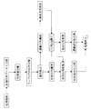
図1は、本発明の一実施形態例を示す構成図である。本実施形態例においては、魚眼レンズなどを利用して、等距離射影(光軸からの入射角に比例した全方位射影)の光学系を組み込んだ全方位カメラ撮像装置を利用した場合を説明する。本発明は、他の全方位射影(等立体角射影、立体射影等)の光学系を組み込んだ全方位カメラ撮像装置で取得した時系列画像に対しても、適用可能である。
【0028】
図1において、1は時系列画像データベース、2は特徴点計測部、3は計測行列変換部、4は計測行列入力部、5は行列分解処理部、6は変換行列算出部、7は物体形状抽出部、8は空間情報復元部、9は視点運動抽出部、10は平面並進運動復元部、11は回転運動復元部である。
【0029】
本実施形態例では、特徴点計測部2において、時系列画像データベース1に格納した時系列の全方位画像において特徴点の時間的変動量を計測し、計測行列変換部3において全方位画像面で変換し、この変換した特徴点座標値の集計データである計測行列を計測行列入力部4により入力し、行列分解処理部5において、因子分解法を応用した方法により、カメラ視点に関する運動行列と、外界の物体の外観を表現する形状行列に分解し、変換行列算出部6において、行列分解処理部5で分解した行列のうち、運動行列の成分からカメラ運動拘束条件を設定し、この条件を満足する変換行列を求め、さらに変換行列を使って運動行列と形状行列を変換し、視点運動抽出部9において該変換した運動行列から運動情報を抽出し、平面並進運動復元部10においてはカメラ視点に関する平面並進運動を、回転運動復元部11においては回転運動を復元し、また物体形状抽出部7において該変換した形状行列を抽出し、空間情報復元部8において外界の物体の形状、または構造、または外観等の空間情報を復元する。
【0030】
図2は、請求項1〜10の発明に関する処理フローである。これら図を元に本発明を、詳細に説明する。
【0031】
ここで、全方位カメラと外界の物体との幾何的位置関係、並びに、本発明で用いているカメラパラメータについて説明しておく。
【0032】
図6に示すように、空間中に設定したXYZ座標系を基準座標系として、この座標系における外界の物体の空間情報(Xj,Yj,Zj)を本発明により復元する。また、このXYZ座標系において、時間的に全方位カメラ視点が移動する。このとき、全方位カメラ、すなわち、光学中心に設定した座標系X0Y0が、XY平面において、図6に示すように、全方位カメラ視点のZ軸と平行な光軸周りの回転、すなわち、X軸との為す角をθiとし、平面上の位置を(Txi,Tyi)として移動するものとする。このXY平面の並進運動(Txi,Tyi)、並びに、方位θiの時間的変化を本発明により復元する。
【0033】
なお、説明の便宜上、初期状態において、全方位カメラ視点に設定したX0Y0座標系の方向と基準座標系のXY座標系の方向とは一致しているものとする。また、全方位カメラ視点、すなわち、光学中心のZ軸の並進運動は無いものとし、方位以外の角、すなわち、進行軸X0周りの回転、並びに、Y0周りの回転の時間的変化は無いのとする。また、全方位カメラの視点、すなわち、光学中心と外界の物体上の点とを直線で結んだとき、XY平面から見たときのX0軸との為す角をρijとする。
【0034】
さらに、図7に、YZ平面での外界の物体と全方位カメラ視点との幾何的関係、並びに、カメラパラメータについて示す。全方位カメラ視点、すなわち、光学中心の位置を(Txi,Tyi)としたとき、外界の物体の点(Xj,Yj,Zj)を直線で結んだとき、XY平面との為す角をΦijとする。
【0035】
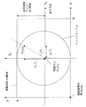
加えて、本発明での魚眼レンズの光学的性質として、図8に示すように、図7での外界に物体の点(Xj,Yj,Zj)と全方位カメラ視点位置、すなわち、光学中心の位置(Txi,Tyi)を結んだ場合、入射角がΦijであるとき、光軸に入射した光(Φij=90度)を画像上の画像中心(Cx,Cy)に射影、入射した光がXY平面で入射した光(Φij=0度)がイメージサークル(全方位画像として映る画像での限界)上に射影される。
【0036】
また、光学的に、等距離射影が成立しており。入射角をΦijとした場合、その角度に比例して画像中心(Cx,Cy)からの距離Rijに射影されるものとする。ここで、焦点距離をfとし、Qは光学的距離と画素との間の比例定数、すなわち、1画素あたりのエリアセンサとの対応付けを表現している。このとき、等距離射影では、式(1)が成り立つ。また、射影点の画像座標値を(xij,yij)とした場合、式(2)に表現できる。
【0037】
【数1】

一方、外界の物体の点は、この全方位カメラの光学的性質により、全方位画像上において、図5に示すようにW×Hの画像サイズで、H/2の半径のイメージサークルより内側の点(xij,yij)に射影される。ここで、X0軸との為す角ρijとすると、光学的性質から、式(3)が成り立つ。
【0039】
【数2】
これで、外界の物体と全方位カメラ視点の位置の幾何学的配置、全方位カメラの光学的性質、並びに、カメラ内部パラメータを定義しておく。
【0041】
図1,図2にもどり、本発明の説明を続ける。
【0042】
始めに、特徴点計測部2は、時系列画像が時間管理で格納されている時系列画像データベース1から時系列画像を取り出して入力し、図2での時系列画像処理のステップを行う。
【0043】
これらのステップでは、まず、時系列画像データベース1から時系列画像を1枚取り出し、これを初期画像として、その画像上に特徴点を配置する。このとき、エッジ検出、ハフ変換、並びに、濃淡の2次元勾配などの画像処理により自動的に特徴点を配置するなどして、初期画像上に特徴点を配置する。このとき配置する特徴点の数をP個(j=1,2,…,P)とし、配置したときの特徴点の2次元座標値として、図5での画像座標系での原点からの座標値(xij,yij):j=1,2,…,Pを記録しておく。
【0044】
次に、特徴点計測部2は、初期画像に続く時系列画像をデータベース1から1枚ずつ読み込み、時系列画像処理のステップにて、初期画像に配置した特徴点を、時系列画像間の濃淡の変化などに着目した手法などを利用することで画像追跡し、各時系列画像(初期画像から第i番目の画像)の特徴点の画像座標値として、図5での画像座標系での原点からの2次元座標値(xij,yij)を記録する。時系列画像を読み出し続けた場合、初期画像に配置した特徴点の中で、画像中から消失したり、オクルージョンなどにより隠れてしまったときは、画像追跡を停止し、特徴点追跡を終了する。特徴点追跡が終了した時点で、読み出した時系列画像の数i=1,2,…,Fは、初期画像を含めてF枚とする。
【0045】
次に、特徴点計測部2は、計測行列記憶を行う。計測行列記憶のステップでは、各時系列画像における特徴点の時間的な画像座標的配置の変化量が記録される。特徴点の時間的な画像座標的配置の変化を行列としてデータ化したものを計測行列[X]と称し、式(4)のデータ形式とする。
【0046】
【数3】
次に、計測行列変換部3は、計測行列変換のステップにて、全方位画像座標値での計測行列に変換する。ここでの全方位画像座標値とは、図5に示すように、画像中心、すなわち、光軸の位置を示し、光学中心の座標値(Cx,Cy)とした場合、この座標値からの相対的な座標値に一時変換しておく。さらに、これを全時系列にわたり、式(2)(3)のρijとΦijを全特徴点から測定し、式(5)で定義するような全方位画像平面上の座標値へ幾何変換する。これを式(6)のようなデータ配列にする。
【0048】
uij=cot(φij)cos(ρij) …式(5(その1))
uij=cot(φij)sin(ρij) …式(5(その2))
【0049】
【数4】
次に、変換された計測行列は計測行列入力部4により行列分解処理部5に入力され、行列分解処理部2において因子分解法処理される。この因子分解法処理のステップでは、全方位カメラ視点の運動と外界の物体の形状、または構造情報を復元する。図3に、因子分解法処理での処理フローを示す。
【0051】
まず、それまでのステップで全方位画像平面上へ変換した計測行列[A]を、計測行列入力部4による計測行列データ入力において読み込む。次に、特異値分解なる数学的手法により、式(7)のように、一意に、3つの行列に行列分解する。
【0052】
【数5】
さらに、行列分解した後、ランク3により、さらに行列を式(8)のように分離する。式(8)の第二項を雑音成分と見なして、式(9)のように雑音除去する。
【0054】
【数6】
次に、雑音成分が除去された運動行列と形状行列とを獲得し、運動行列についてカメラ運動に関する拘束条件を設定し、これを満足するように、[Q]を決定する。すなわち、式(12)に示すように、行列[Q]を作用させた後の行列を[M]とし、各行についてmi,niとし、要素が式(13)であるとする。この行列の要素mi,niが、式(14),(15),(16)の拘束条件を満足するようにする。ただし、行列[Q]の要素を、式(17)に示す要素とする。このとき、式(12)の要素から、式(14)から式(18)を経て(19)の計算式を設定する。また、式(12)の要素から、式(15)から式(20)を経て(21)の計算式を設定する。また、式(12)の要素から、式(16)から式(22)を経て(23)の計算式を設定する。式(19),(21),(23)から、式(24)の行列[Q][Q]Tを求める計算式を設定する。行列[Q][Q]Tを求めるときは、式(25)の演算を行い、この計算で得た要素から、式(26)のように固有値分解し、式(27)であるとする。次に、式(28)を使って、式(25)で得た元の行列[Q]の要素Q11,Q12,Q21,Q22を求める。
【0056】
【数7】
m2 ix+m2 iy=1 …式(14)
n2 ix+n2 iy=1 …式(15)
mixnix+miyniy=0 …式(16)
【0058】
【数8】
【数9】
【数10】
または、式(26)の固有値分解を行い、式(26)の右辺の2番目の行列の固有値の平方根を対角要素とした行列、すなわち、式(28)の右辺の1番目の行列を求める。次に、式(28−1)に示すように固有ベクトルの符号判定を行い、(qix,qiy)i=1,2を決定し、式(28)により[Q]を求める。
【0062】
次に、変換行列算出部6は、求めた行列[Q]によって、式(29)により運動行列の変換処理を行い、並びに、式(30)により形状行列変換の処理を行う。これで得られた運動成分[M']、並びに、物体形状成分[S']を出力し、因子分解法処理を終える。
【0063】
【数11】
図1、図2に戻り、回転運動復元部11は回転成分計算を、平面並進運動復元部10は平面並進成分計算を、並びに空間情報復元分解8は空間情報復元計算を、それぞれ行う。
【0065】
まず、視点運動抽出部9により、全フレームでの回転成分を抽出し、回転運動復元部11により、初期画像での運動成分が式(31)となるように、全フレームにおいて、方位正規化計算をする。
【0066】
【数12】
すなわち、まず、式(29)で求めた行列[M]について、式(32)の運動成分とし、初期フレームでの行ベクトルを、式(33)のように取り出す。次に、このベクトルに直交するベクトルk1を式(34)のように生成し、これらベクトルを要素とする行列[N]を生成する。この行列を使って、式(36)のように変換をすることで、方位正規化計算を行い、行列[M]を得る。
【0068】
iT 1=[U'11 U'12 0] …式(33(その1))
jT 1=[U'1+F,1 U'1+F,2 0] …式(33(その2))
kT 1=[0 0 1]] …式(34)
【0069】
【数13】
次に、回転運動復元部11は、各フレームに対して、式(37)、または、式(38)を使って方位回転θiを計算する。
【0071】
【数14】
一方、図4では、物体形状抽出部7により並進成分を抽出して、平面並進運動復元部10により、各フレームでの成分から、平面運動としての並進成分を計算する。ここでは、式(13)の第3列目の要素を抽出し、各フレームに対して、式(39)に従って、平面運動での並進成分(T(i)x,T(i)y)を復元する。
【0073】
【数15】
これで、図4の回転成分計算、および並進運動計算を終了する。
【0075】
続いて、図1、図2に戻り、空間情報復元部8による空間情報復元処理を行う。ここでの空間情報復元処理では、式(30)の行列要素が、式(40)であるとすると、式(41)に従って、外界の物体形状、または、構造に関する空間情報を表現する3次元座標値が復元できる。
【0076】
以上、本発明の実施形態例により、全方位映像の特徴点の時間的動きから、全方位カメラ視点の運動、すなわち、方位運動とXY平面での並進運動、並びに、外界の物体の形状、または構造の空間情報、すなわち、3次元座標値を復元することができる。
【0077】
【数16】
なお、本発明では、全方位光学系において、式(2)に示す光軸からの入射角に比例した光学射影の場合、時系列の全方位画像上の特徴点座標値について、原点と設定した位置から、式(2)の全方位射影式を使って仰角のφijと位相ρijを求め、式(5(その1))と式(5(その2))で表現する座標系へ幾何変換し、この座標平面上での特徴点座標値の計測行列[A]から行列分解を行うようにしても良いし、式(42)に示す光軸からの入射角の半角の正弦に比例した光学射影の場合、時系列の全方位画像上の特徴点座標値について、原点と設定した位置から、式(42)の全方位射影式を使って仰角のφijと位相ρijを求め、式(5(その1))と式(5(その2))で表現する座標系へ幾何変換し、この座標平面上での特徴点座標値の計測行列[A]から行列分解を行うようにしても良いし、式(43)に示す光軸からの入射角の半角の正接に比例した光学射影の場合、時系列の全方位画像上の特徴点座標値について、原点と設定した位置から、式(43)の全方位射影式を使って仰角のφijと位相ρijを求め、式(5(その1))と式(5(その2))で表現する座標系へ幾何変換し、この座標平面上での特徴点座標値の計測行列[A]から行列分解を行うようにしても良い。
【0079】
【数17】
なお、図1で示した装置における各部の一部もしくは全部の機能をコンピュータのプログラムで構成し、そのプログラムをコンピュータを用いて実行して本発明を実現することができること、あるいは、図2〜図4で示した処理の手順をコンピュータのプログラムで構成し、そのプログラムをコンピュータに実行させることができることは言うまでもなく、コンピュータでその機能を実現するためのプログラム、あるいは、コンピュータにその処理の手順を実行させるためのプログラムを、そのコンピュータが読み取り可能な記録媒体、例えば、FD(フロッピーディスク(登録商標))や、MO、ROM、メモリカード、CD、DVD、リムーバブルディスクなどに記録して、保存したり、配布したりすることが可能である。また、上記のプログラムをインターネットや電子メールなど、ネットワークを通して提供することも可能である。
【0081】
【発明の効果】
本発明によれば、全方位カメラを使って取得した時系列画像全般(移動手段を利用して撮影した車載映像、海上映像、空撮映像、屋内映像など)から、対象物に関する物体形状等の空間情報を高精度に獲得、復元することが可能となる。また、これまでの測量技術並の高精度な3次元立体視が可能となる。さらに、全方位カメラ視点のカメラ光軸周りの回転、並びに、XY平面運動からなる方位運動を正確に復元することが可能となる。
【図面の簡単な説明】
【図1】本発明の基本的な実施形態例を示す構成図である。
【図2】本実施形態例での処理フローを説明する図である。
【図3】本実施形態例での因子分解法処理フローを説明する図である。
【図4】本実施形態例でのカメラ視点の回転運動、及び並進運動の復元を説明する図である。
【図5】全方位画像面の座標値を説明する図である。
【図6】XY平面でのカメラパラメータを説明する図である。
【図7】垂直平面とYZ平面、光学系の関係を説明する図である。
【図8】等距離射影を説明する図である。
【符号の説明】
1…時系列画像データベース
2…特徴点計測部
3…計測行列変換部
4…計測行列入力部
5…行列分解処理部
6…変換行列算出部
7…物体形状抽出部
8…空間情報復元部
9…視点運動抽出部
10…平面並進運動復元部
11…回転運動復元部[0001]
BACKGROUND OF THE INVENTION
The present invention relates to time series image data acquired by an image input device or the like, and measurement or acquisition and restoration of a spatial shape or a spatial structure of an object, and motion related to an optical viewpoint of an image input device (camera). In addition, it relates to restoring the temporal motion of the subject (object). In particular, it relates to camera movement and object shape restoration in computer vision.
[0002]
In addition, the present invention can be used for in-vehicle images acquired using an omnidirectional camera, marine video from a ship, time series images such as aerial photography, and in particular, posture and plane motion related to an omnidirectional camera viewpoint. In addition, it relates to the restoration of spatial information such as the shape of the outside world reflected in the time-series video, that is, the shape of the appearance of the subject (object).
[0003]
[Prior art]
In the computer vision field, methods for measuring or acquiring the shape of an object from time-series image data include three-dimensional analysis methods using stereo measurement and epipolar plane analysis. Recently, there is a factorization method (the following document [1]) as a representative method for simultaneously measuring or acquiring three-dimensional information related to camera motion and the shape of a subject (object). According to these methods, it is possible to acquire and restore information related to the spatial shape or spatial structure and motion related to the camera viewpoint from a plurality of time-series images in which the object is photographed.
[0004]
Reference [1] C. Tomasi and T. Kanade; “Shape and Motion from Image Streams Under Orthography: A Factorization Method”, International Journal of Computer Vision, Vol. 9, No. 2, 1992.
[0005]
However, it is difficult to obtain images seamlessly in time-series images taken by moving the shooting camera using moving means, etc. due to the shooting environment and minute movements of the shooting camera. In some cases, random noise is mixed in and it is difficult to accurately restore the camera motion.
[0006]
Furthermore, camera motion and object shape reconstruction in Euclidean space can be performed by factorization from image coordinate values that can be expressed in an orthogonal coordinate system with a plane image plane. In order to frame-in or frame-out, the rotational motion of the image input device is restored globally or in the long-term, and the shape of the external object is large-scaled, globally, or long-term It is difficult to restore. On the other hand, in order to avoid such a problem of a finite field angle, as a means for acquiring a 360-degree panoramic image at a time, the camera motion and the object shape are restored from a time-series image acquired using an omnidirectional camera. Can be considered. However, conventional approaches based on epipolar analysis and stereo vision have been applied to time-series omnidirectional images. From time-series images with noise added, the camera motion and object shape in Euclidean space can be easily detected. There are problems such as inability to restore.
[0007]
By the way, outdoors, it is possible to sense a state related to position information and posture information of image input by using a sensing device such as GPS, differential GPS, and gyro, which has become highly accurate in recent years.
[0008]
[Problems to be solved by the invention]
In general, when simultaneously restoring camera movement and the shape of an object from a time-series image acquired from an image input device (camera), the influence of random noise mixed in the time-series image or the minuteness of the camera at the time of shooting It is difficult to accurately restore correct movements. In order to deal with such a problem, the above-described factorization method (reference [1]) exists in computer vision.
[0009]
On the other hand, position information measurement using a GPS device or the like is limited to a geometrical arrangement of GPS satellites or a time zone with good sensing conditions. In addition, there is a problem that a place where trees or high-rise buildings stand in the environment surrounding position measurement is a disadvantageous condition for sensing.
[0010]
In addition, in a time-series image acquired in a shooting environment that visualizes a 360-degree landscape at a time, such as an omnidirectional camera, using a moving means, a measurement method that applies the principle of stereo vision can be used to Spatial information can be acquired and restored, but since the camera moves minutely depending on the arrangement of the moving means and the imaging device and the shooting environment, seamless time-series images cannot be easily acquired. Therefore, the influence of random noise is large, and it is impossible to restore the camera movement and the shape of the object at the same time and with high accuracy at all times.
[0011]
The present invention provides position information that cannot be measured even by surveying using remote sensing, etc., and spatial noise of external objects using methods such as stereo vision. It is an object of the present invention to provide a method and apparatus for accurately restoring temporal fluctuations relating to the posture and position of a camera viewpoint, that is, reconstructing motion, and acquiring and restoring spatial information of external objects.
[0012]
[Means for Solving the Problems]
In order to solve the above-described problems, the present invention relates to the movement of the omnidirectional camera viewpoint regarding the time series in the time-series omnidirectional image obtained by the image input means, and the shape or structure of the external object as the subject. Or a method of reconstructing spatial information including appearance, in an image coordinate system set on a time-series image, measuring a temporal variation amount of a feature point in each time-series image, and calculating the feature point coordinate value A first step of converting to another coordinate system; and a measurement matrix, which is data obtained by aggregating the converted feature point coordinate values, is subjected to matrix decomposition, a motion matrix relating to the camera viewpoint, and a shape matrix expressing the appearance of an object in the outside world In the second step of decomposing, and in the decomposed motion matrix, a transformation matrix is obtained so as to satisfy the conditions set for defining motion, and the transformation matrix is used to Information corresponding to rolling motion, a third step of calculating and restoring information corresponding to translational motion, a fourth step of restoring a shape matrix expressing the appearance of the object using the transformation matrix, and the restoration The fifth step of restoring the spatial information of the object in the outside world using the shape matrix thus obtained is used as an omnidirectional camera viewpoint motion and object shape restoration method.
[0013]
Alternatively, in the omnidirectional camera viewpoint motion restoration and object shape restoration method described above, the second step is a matrix decomposition by factorization of a measurement matrix that is data obtained by tabulating converted feature point coordinate values; A omnidirectional camera viewpoint motion and object shape restoration method comprising the steps of denoising from the decomposed matrix and obtaining a motion matrix and a shape matrix from the denoised matrix .
[0014]
Alternatively, in the omnidirectional camera viewpoint motion restoration and object shape restoration method described above, in the first step, in converting the feature point coordinate value in each time-series image into another coordinate system, Based on the omnidirectional projection proportional to the incident angle from the optical axis, the image coordinate value is converted into a coordinate value of another coordinate system, and in the second step, the matrix is decomposed by factorization. An omnidirectional camera viewpoint motion and object shape restoration method characterized in that factorization is performed on a measurement matrix consisting of values.
[0015]
Alternatively, in the omnidirectional camera viewpoint motion restoration and object shape restoration method described above, in the first step, in converting the feature point coordinate value in each time-series image into another coordinate system, , Based on the projection proportional to the sine of the half angle of the incident angle from the optical axis, the image coordinate value is converted into a coordinate value of another coordinate system, and the conversion is performed in the matrix decomposition by factorization in the second step. An omnidirectional camera viewpoint motion and object shape restoration method characterized in that factorization is performed on a measurement matrix composed of coordinate values obtained.
[0016]
Alternatively, in the omnidirectional camera viewpoint motion restoration and object shape restoration method described above, in the first step, in converting the feature point coordinate value in each time-series image into another coordinate system, The image coordinate value is converted to a coordinate value of another coordinate system based on the projection proportional to the tangent of the half angle of the incident angle from the optical axis, and the conversion is performed in the matrix decomposition by factorization in the second step. An omnidirectional camera viewpoint motion and object shape restoration method characterized in that factorization is performed on a measurement matrix composed of coordinate values obtained.
[0017]
Alternatively, in the omnidirectional camera viewpoint motion restoration and object shape restoration method described above, in the first step, when converting the feature point coordinate values in each time series image to another coordinate system, the time series omnidirectional The coordinate value of the feature point on the image is geometrically transformed into a coordinate system expressed by the phase from the origin and the set position, and in the second step, matrix decomposition is performed from the measurement matrix of the feature point coordinate value on the phase plane. The omnidirectional camera viewpoint movement and the object shape restoration method characterized by the above are used as means.
[0018]
Alternatively, in the omnidirectional camera viewpoint motion restoration and object shape restoration method, the fourth step uses the transformation matrix obtained in the third step when calculating and restoring information corresponding to the rotational motion. In the obtained motion matrix, an omnidirectional camera viewpoint motion and object shape restoration method characterized by restoring rotational motion around the optical axis is used as means.
[0019]
Alternatively, in the omnidirectional camera viewpoint motion restoration and object shape restoration method described above, in the fourth step, when calculating and restoring information corresponding to the translational motion, the transformation matrix obtained in the third step is used. The omnidirectional camera viewpoint is characterized by taking out information corresponding to the translational movement of the omnidirectional camera viewpoint and converting it into a planar movement in the image coordinate system set when the coordinate values of the feature points on the time-series image are measured The motion and object shape restoration method is used as means.
[0020]
Alternatively, in the omnidirectional camera viewpoint motion restoration and object shape restoration method described above, in the fifth step, one component in the shape matrix obtained by converting the shape matrix representing the appearance of the object obtained in the third step And omnidirectional camera viewpoint motion and object shape restoration method characterized in that the spatial information of feature points is restored.
[0021]
Alternatively, in the above-described omnidirectional camera viewpoint motion restoration and object shape restoration method, in the third step, when obtaining a transformation matrix, for a matrix element satisfying the conditional expression, its principal component and its principal component An omnidirectional camera viewpoint motion and object shape restoration method characterized in that a transformation matrix is obtained from such a code vector.
[0022]
Alternatively, in a time-series omnidirectional image acquired by an image input device, it is a device that restores spatial information including the motion of the omnidirectional camera viewpoint with respect to time-series and the shape, structure, or appearance of an external object. In the image coordinate system set on the time series image, a feature point measurement unit that measures the temporal variation of the feature point in each time series image, and the feature point coordinate value is converted into another coordinate system. A shape that represents the appearance of the motion matrix related to the camera viewpoint and the appearance of the object in the outside world by decomposing the measurement matrix, which is the data summing up the converted feature point coordinate values, decomposing the matrix, and removing noise A matrix decomposition processing unit for decomposing the matrix, a transformation matrix calculating unit for obtaining a transformation matrix so as to satisfy a condition set for defining motion in the decomposed motion matrix, and using the transformation matrix, Bearing Using the transformation matrix, the shape matrix expressing the appearance of the object is restored by using the transformation matrix and the information corresponding to the rotational movement of the viewpoint and the viewpoint movement restoring unit that calculates and restores the information corresponding to the translational movement. An omnidirectional camera viewpoint movement and object shape restoration device characterized by having a spatial information restoration unit that restores the spatial information of an object in the outside world using the shape matrix thus formed.
[0023]
Alternatively, an omnidirectional camera viewpoint movement and object shape restoration program is provided as a program for causing a computer to execute the steps in the omnidirectional camera viewpoint movement and object shape restoration method.
[0024]
Alternatively, an omnidirectional camera viewpoint characterized in that a program for causing a computer to execute the steps in the omnidirectional camera viewpoint movement and object shape restoration method described above is recorded on a recording medium readable by the computer. A recording medium on which a motion and object shape restoration program is recorded is used as means.
[0025]
In the present invention, in the omnidirectional projection formula using the optical properties of the omnidirectional camera, by applying the factorization method (reference [1]), the temporal movement of the feature points measured from the time-series images, that is, Conditions for reconstructing camera motion by removing random noise from temporal fluctuation values in omnidirectional space, and decomposing the camera motion into omnidirectional camera viewpoints and elements representing spatial information of external objects Using the transformation matrix that satisfies this conditional expression, acquire and restore motions consisting of posture and position related to the omnidirectional camera viewpoint and spatial information of external objects, that is, object shape, structure, appearance, etc. This makes it possible to accurately determine the shape of an object related to an object from all time-series images acquired using an omnidirectional camera (vehicle-mounted video, sea video, aerial video, indoor video, etc. taken using a moving means). Obtained makes it possible to restore. In addition, high-accuracy three-dimensional stereoscopic viewing similar to conventional surveying techniques is possible. Furthermore, it is possible to accurately restore the rotation of the omnidirectional camera viewpoint around the camera optical axis and the camera motion including the XY plane motion.
[0026]
DETAILED DESCRIPTION OF THE INVENTION
Hereinafter, embodiments of the present invention will be described in detail with reference to the drawings.
[0027]
FIG. 1 is a block diagram showing an embodiment of the present invention. In this embodiment, a case will be described in which an omnidirectional camera imaging apparatus incorporating an optical system of equidistant projection (omnidirectional projection proportional to the incident angle from the optical axis) using a fisheye lens or the like is described. The present invention can also be applied to a time-series image acquired by an omnidirectional camera imaging apparatus incorporating an optical system of other omnidirectional projection (equilateral solid angle projection, stereoscopic projection, etc.).
[0028]
In FIG. 1, 1 is a time-series image database, 2 is a feature point measurement unit, 3 is a measurement matrix conversion unit, 4 is a measurement matrix input unit, 5 is a matrix decomposition processing unit, 6 is a transformation matrix calculation unit, and 7 is an object shape. An extraction unit, 8 is a spatial information restoration unit, 9 is a viewpoint motion extraction unit, 10 is a plane translational motion restoration unit, and 11 is a rotational motion restoration unit.
[0029]
In the present embodiment, the feature
[0030]
FIG. 2 is a process flow relating to the inventions of claims 1 to 10. The present invention will be described in detail based on these drawings.
[0031]
Here, the geometric positional relationship between the omnidirectional camera and the object in the outside world, and the camera parameters used in the present invention will be described.
[0032]
As shown in FIG. 6, an XYZ coordinate system set in the space is used as a reference coordinate system, and space information (Xj, Yj, ZjIs restored according to the invention. In this XYZ coordinate system, the omnidirectional camera viewpoint moves in time. At this time, the omnidirectional camera, that is, the coordinate system X set at the optical center0Y0In the XY plane, as shown in FIG. 6, the rotation about the optical axis parallel to the Z axis of the omnidirectional camera viewpoint, that is, the angle made with the X axis is θiAnd the position on the plane is (Txi, Tyi). Translational movement of this XY plane (Txi, Tyi) And orientation θiIs restored by the present invention.
[0033]
For convenience of explanation, in the initial state, X set to the omnidirectional camera viewpoint0Y0It is assumed that the direction of the coordinate system matches the direction of the XY coordinate system of the reference coordinate system. Also, it is assumed that there is no translational movement of the omnidirectional camera viewpoint, that is, the optical axis Z axis, and an angle other than the azimuth, that is, the traveling axis X0Rotation around as well as Y0It is assumed that there is no temporal change in the surrounding rotation. Also, the viewpoint of the omnidirectional camera, that is, the X when viewed from the XY plane when the optical center and a point on the object in the outside world are connected by a straight line.0The angle made with the axis is ρijAnd
[0034]
Further, FIG. 7 shows the geometric relationship between the external object on the YZ plane and the omnidirectional camera viewpoint, and the camera parameters. The omnidirectional camera viewpoint, that is, the position of the optical center (Txi, Tyi), The point of the external object (Xj, Yj, Zj) Is connected by a straight line, the angle made with the XY plane is ΦijAnd
[0035]
In addition, as shown in FIG. 8, the optical property of the fisheye lens in the present invention is that an object point (Xj, Yj, Zj) And the omnidirectional camera viewpoint position, that is, the position of the optical center (Txi, Tyi), The incident angle is ΦijThe light incident on the optical axis (Φij= 90 degrees) is the image center (Cx, Cy) And the incident light is incident on the XY plane (Φij= 0 degree) is projected onto an image circle (limit in an image displayed as an omnidirectional image).
[0036]
Optically, equidistant projection is established. The incident angle is ΦijThe center of the image (Cx, CyDistance R fromijTo be projected. Here, the focal length is f, and Q represents a proportionality constant between the optical distance and the pixel, that is, the correspondence with the area sensor per pixel. At this time, Formula (1) is established in equidistant projection. Also, the image coordinate value of the projection point is set to (xij, Yij), It can be expressed in equation (2).
[0037]
[Expression 1]
On the other hand, due to the optical properties of this omnidirectional camera, the point of the object in the outside world is an image size of W × H as shown in FIG. Point (xij, Yij). Where X0The angle ρ with the axisijThen, Formula (3) is formed from optical properties.
[0039]
[Expression 2]
Thus, the geometric arrangement of the positions of the external object and the omnidirectional camera viewpoint, the optical properties of the omnidirectional camera, and the camera internal parameters are defined.
[0041]
Returning to FIG. 1 and FIG. 2, the description of the present invention will be continued.
[0042]
First, the feature
[0043]
In these steps, first, one time-series image is extracted from the time-series image database 1, and this is used as an initial image, and feature points are arranged on the image. At this time, the feature points are arranged on the initial image by automatically arranging the feature points by image processing such as edge detection, Hough transform, and two-dimensional gradient. At this time, the number of feature points to be arranged is P (j = 1, 2,..., P), and coordinates from the origin in the image coordinate system in FIG. Value (xij, Yij): J = 1, 2,..., P are recorded.
[0044]
Next, the feature
[0045]
Next, the feature
[0046]
[Equation 3]
Next, the measurement matrix conversion unit 3 converts it into a measurement matrix with omnidirectional image coordinate values in the measurement matrix conversion step. As shown in FIG. 5, the omnidirectional image coordinate value here indicates the center of the image, that is, the position of the optical axis, and the coordinate value (Cx, Cy), It is temporarily converted into a relative coordinate value from this coordinate value. Further, this is applied over the entire time series, and ρ in equations (2) and (3)ijAnd ΦijAre measured from all feature points and geometrically transformed into coordinate values on the omnidirectional image plane as defined by equation (5). This is converted into a data array as shown in equation (6).
[0048]
uij= Cot (φij) Cos (ρij) ... Formula (5 (part 1))
uij= Cot (φij) Sin (ρij) ... Formula (5 (2))
[0049]
[Expression 4]
Next, the converted measurement matrix is input to the matrix
[0051]
First, the measurement matrix [A] converted to the omnidirectional image plane in the previous steps is read in the measurement matrix data input by the measurement
[0052]
[Equation 5]
Further, after matrix decomposition, the matrix is further separated as shown in Expression (8) by rank 3. The second term of equation (8) is regarded as a noise component, and noise is removed as in equation (9).
[0054]
[Formula 6]
Next, the motion matrix and shape matrix from which the noise component has been removed are obtained, a constraint condition regarding camera motion is set for the motion matrix, and [Q] is determined so as to satisfy this. That is, as shown in Expression (12), the matrix after applying the matrix [Q] is [M], and m for each rowi, NiAnd the element is represented by equation (13). Element m of this matrixi, NiHowever, the constraint conditions of the expressions (14), (15), and (16) are satisfied. However, an element of the matrix [Q] is an element shown in Expression (17). At this time, the calculation formula (19) is set from the formula (14) to the formula (18) from the elements of the formula (12). Further, the calculation formula (21) is set from the formula (12) through the formula (15) to the formula (20). Also, the calculation formula (23) is set from the formula (12) through the formula (16) from the formula (12). From equations (19), (21), and (23), the matrix [Q] [Q] of equation (24)TSet the formula to calculate. Matrix [Q] [Q]TIs obtained by performing the calculation of Expression (25), eigenvalue decomposition is performed as shown in Expression (26) from the elements obtained by this calculation, and Expression (27) is assumed. Next, using equation (28), element Q of the original matrix [Q] obtained by equation (25)11, Q12, Qtwenty one, Qtwenty twoAsk for.
[0056]
[Expression 7]
m2 ix+ M2 iy= 1 ... Formula (14)
n2 ix+ N2 iy= 1 ... Formula (15)
mixnix+ Miyniy= 0 ... Formula (16)
[0058]
[Equation 8]
[Equation 9]
[Expression 10]
Alternatively, eigenvalue decomposition of Expression (26) is performed to obtain a matrix having the square root of the eigenvalue of the second matrix on the right side of Expression (26) as a diagonal element, that is, the first matrix on the right side of Expression (28). . Next, as shown in Expression (28-1), sign determination of the eigenvector is performed, and (qix, Qiy) I = 1, 2 is determined, and [Q] is obtained by the equation (28).
[0062]
Next, the transformation matrix calculation unit 6 performs a motion matrix transformation process according to Equation (29) using the obtained matrix [Q], and performs a shape matrix transformation process according to Equation (30). The motion component [M ′] and the object shape component [S ′] obtained in this way are output, and the factorization method processing ends.
[0063]
## EQU11 ##
Returning to FIGS. 1 and 2, the rotational
[0065]
First, the viewpoint motion extraction unit 9 extracts rotational components in all frames, and the rotational
[0066]
[Expression 12]
That is, first, the matrix [M] obtained by Expression (29) is used as the motion component of Expression (32), and the row vector at the initial frame is extracted as Expression (33). Next, a vector k orthogonal to this vector1Is generated as shown in Expression (34), and a matrix [N] having these vectors as elements is generated. Using this matrix, transformation is performed as shown in Expression (36) to perform azimuth normalization calculation to obtain matrix [M].
[0068]
iT 1= [U '11 U '12 0] Formula (33 (Part 1))
jT 1= [U '1 + F,1 U '1 + F,2 0] Formula (33 (2))
kT 1= [0 0 1]] ... Formula (34)
[0069]
[Formula 13]
Next, the rotational
[0071]
[Expression 14]
On the other hand, in FIG. 4, the translational component is extracted by the object
[0073]
[Expression 15]
This completes the rotation component calculation and the translational motion calculation of FIG.
[0075]
Subsequently, returning to FIG. 1 and FIG. 2, the spatial information restoring process by the spatial
[0076]
As described above, according to the embodiment of the present invention, from the temporal movement of the feature point of the omnidirectional video, the movement of the omnidirectional camera viewpoint, that is, the azimuth movement and the translational movement in the XY plane, and the shape of the object in the outside world, or The spatial information of the structure, that is, the three-dimensional coordinate value can be restored.
[0077]
[Expression 16]
In the present invention, in the omnidirectional optical system, in the case of optical projection proportional to the angle of incidence from the optical axis shown in equation (2), the feature point coordinate value on the time-series omnidirectional image is set as the origin. From the position, the elevation angle φ using the omnidirectional projection formula (2)ijAnd phase ρijAnd geometrically transform into the coordinate system expressed by Equation (5 (Part 1)) and Equation (5 (Part 2)), and perform matrix decomposition from the measurement matrix [A] of the feature point coordinate values on this coordinate plane. In the case of optical projection proportional to the half angle sine of the incident angle from the optical axis shown in equation (42), the feature point coordinate value on the time-series omnidirectional image is set as the origin. From the position, the elevation angle φ using the omnidirectional projection formula (42)ijAnd phase ρijAnd geometrically transform into the coordinate system expressed by Equation (5 (Part 1)) and Equation (5 (Part 2)), and perform matrix decomposition from the measurement matrix [A] of the feature point coordinate values on this coordinate plane. In the case of optical projection proportional to the tangent of the half angle of the incident angle from the optical axis shown in Expression (43), the feature point coordinate value on the time-series omnidirectional image is set as the origin. From the position, using the omnidirectional projection formula (43), the elevation angle φijAnd phase ρijAnd geometrically transform into the coordinate system expressed by Equation (5 (Part 1)) and Equation (5 (Part 2)), and perform matrix decomposition from the measurement matrix [A] of the feature point coordinate values on this coordinate plane. You may make it do.
[0079]
[Expression 17]
1 may be realized by configuring a part or all of the functions of each unit in the apparatus shown in FIG. 1 with a computer program and executing the program using the computer, or FIG. It goes without saying that the processing procedure shown in 4 can be constituted by a computer program and the program can be executed by the computer, and the program for realizing the function by the computer or the processing procedure is executed by the computer. The program to be recorded on a computer-readable recording medium such as FD (floppy disk (registered trademark)), MO, ROM, memory card, CD, DVD, removable disk, etc. Can be distributed. It is also possible to provide the above program through a network such as the Internet or electronic mail.
[0081]
【The invention's effect】
According to the present invention, from general time-series images acquired using an omnidirectional camera (vehicle-mounted video, marine video, aerial video, indoor video, etc. captured using a moving means) Spatial information can be acquired and restored with high accuracy. In addition, high-accuracy three-dimensional stereoscopic viewing similar to conventional surveying techniques is possible. Furthermore, it is possible to accurately restore the rotation of the omnidirectional camera viewpoint around the camera optical axis and the azimuth motion consisting of the XY plane motion.
[Brief description of the drawings]
FIG. 1 is a block diagram showing a basic embodiment of the present invention.
FIG. 2 is a diagram illustrating a processing flow in the present embodiment.
FIG. 3 is a diagram for explaining a factorization method processing flow in the present embodiment example;
FIG. 4 is a diagram for explaining the rotational movement of a camera viewpoint and the restoration of translational movement in the present embodiment.
FIG. 5 is a diagram illustrating coordinate values on an omnidirectional image plane.
FIG. 6 is a diagram illustrating camera parameters on an XY plane.
FIG. 7 is a diagram illustrating a relationship between a vertical plane, a YZ plane, and an optical system.
FIG. 8 is a diagram for explaining equidistant projection.
[Explanation of symbols]
1. Time series image database
2 ... Feature point measurement unit
3 ... Measurement matrix converter
4 ... Measurement matrix input section
5 ... Matrix decomposition processor
6 ... Conversion matrix calculation unit
7 ... Object shape extraction unit
8 ... Spatial information restoration unit
9 ... Viewpoint motion extraction unit
10 ... plane translational motion restoration part
11 ... Rotational motion restoration part
Claims (13)
時系列画像上に設定した画像座標系において、各時系列画像中の特徴点の時間的変動量を測定し、その特徴点座標値を別の座標系に変換する第1ステップと、
該変換された特徴点座標値を集計したデータである計測行列を行列分解し、カメラ視点に関する運動行列と、外界の物体の外観を表現する形状行列に分解する第2ステップと、
該分解された運動行列において、運動を規定するために設定した条件を満足するように変換行列を求めるとともに、該変換行列を使って、全方位カメラ視点の回転運動に対応する情報と、並進運動に対応する情報を計算し復元する第3ステップと、
該変換行列を使って、該物体の外観を表現する形状行列を復元する第4ステップと、
該復元された形状行列を使って、外界の物体の空間情報を復元する第5ステップと、を有する
ことを特徴とする全方位カメラ視点運動並びに物体形状復元方法。In a time-series omnidirectional image acquired by the image input means, a method of restoring spatial information including the movement of the omnidirectional camera viewpoint with respect to the time-series and the shape, structure, or appearance of the external object that is the subject. There,
A first step of measuring a temporal variation amount of a feature point in each time series image in an image coordinate system set on the time series image, and converting the feature point coordinate value to another coordinate system;
A second step of decomposing a measurement matrix, which is data obtained by aggregating the converted feature point coordinate values, into a motion matrix related to a camera viewpoint and a shape matrix expressing the appearance of an object in the outside world;
In the decomposed motion matrix, a transformation matrix is obtained so as to satisfy the conditions set for defining the motion, and information corresponding to the rotational motion of the omnidirectional camera viewpoint and translational motion are obtained using the transformation matrix. A third step of calculating and restoring information corresponding to
A fourth step of restoring a shape matrix representing the appearance of the object using the transformation matrix;
An omnidirectional camera viewpoint motion and object shape restoration method, comprising: a fifth step of restoring space information of an object in the outside world using the restored shape matrix.
第2ステップは、
変換された特徴点座標値を集計したデータである計測行列を因子分解により行列分解するステップと、
該分解された行列から雑音除去するステップと、
該雑音除去された行列から運動行列と形状行列を獲得するステップと、を有する
ことを特徴とする全方位カメラ視点運動並びに物体形状復元方法。An omnidirectional camera viewpoint motion restoration and object shape restoration method according to claim 1,
The second step is
A matrix decomposition by factorization of a measurement matrix that is data obtained by aggregating converted feature point coordinate values;
Denoising from the decomposed matrix;
Obtaining a motion matrix and a shape matrix from the denoised matrix, and an omnidirectional camera viewpoint motion and object shape restoration method.
第1ステップでは、各時系列画像中の特徴点座標値を別の座標系に変換するのに際し、全方位光学系において、光軸からの入射角に比例した全方位射影に基づいて、画像座標値から別の座標系の座標値に変換し、
第2ステップにおける、因子分解により行列分解するステップでは、該変換した座標値からなる計測行列に対して、因子分解を行う
ことを特徴とする全方位カメラ視点運動並びに物体形状復元方法。An omnidirectional camera viewpoint motion restoration and object shape restoration method according to claim 2,
In the first step, when converting the feature point coordinate values in each time-series image to another coordinate system, the image coordinates are calculated in the omnidirectional optical system based on the omnidirectional projection proportional to the incident angle from the optical axis. Convert the value into a coordinate value in another coordinate system,
An omnidirectional camera viewpoint movement and object shape restoration method characterized in that, in the step of performing matrix decomposition by factorization in the second step, factorization is performed on the measurement matrix composed of the converted coordinate values.
第1ステップでは、各時系列画像中の特徴点座標値を別の座標系に変換するのに際し、全方位光学系において、光軸からの入射角の半角の正弦に比例した射影に基づいて、画像座標値から別の座標系の座標値に変換し、
第2ステップにおける、因子分解により行列分解するステップでは、該変換した座標値からなる計測行列に対して、因子分解を行う
ことを特徴とする全方位カメラ視点運動並びに物体形状復元方法。An omnidirectional camera viewpoint motion restoration and object shape restoration method according to claim 2,
In the first step, when converting the feature point coordinate value in each time-series image to another coordinate system, in the omnidirectional optical system, based on the projection proportional to the sine of the half angle of the incident angle from the optical axis, Convert image coordinate values to coordinate values in another coordinate system,
An omnidirectional camera viewpoint movement and object shape restoration method characterized in that, in the step of performing matrix decomposition by factorization in the second step, factorization is performed on the measurement matrix composed of the converted coordinate values.
第1ステップでは、各時系列画像中の特徴点座標値を別の座標系に変換するのに際し、全方位光学系において、光軸からの入射角の半角の正接に比例した射影に基づいて、画像座標値から別の座標系の座標値に変換し、
第2ステップにおける、因子分解により行列分解するステップでは、該変換した座標値からなる計測行列に対して、因子分解を行う
ことを特徴とする全方位カメラ視点運動並びに物体形状復元方法。An omnidirectional camera viewpoint motion restoration and object shape restoration method according to claim 2,
In the first step, when converting the feature point coordinate value in each time series image to another coordinate system, in the omnidirectional optical system, based on the projection proportional to the tangent of the half angle of the incident angle from the optical axis, Convert image coordinate values to coordinate values in another coordinate system,
An omnidirectional camera viewpoint movement and object shape restoration method characterized in that, in the step of performing matrix decomposition by factorization in the second step, factorization is performed on the measurement matrix composed of the converted coordinate values.
第1ステップでは、各時系列画像中の特徴点座標値を別の座標系に変換するのに際し、時系列の全方位画像上の特徴点の座標値について、原点と設定した位置からの位相で表現する座標系へ幾何変換し、
第2ステップでは、該位相平面上での特徴点座標値の計測行列から行列分解する
ことを特徴とする全方位カメラ視点運動並びに物体形状復元方法。An omnidirectional camera viewpoint motion restoration and object shape restoration method according to any one of claims 1 to 5,
In the first step, when converting the feature point coordinate values in each time-series image to another coordinate system, the coordinate values of the feature points on the time-series omnidirectional image are calculated based on the phase from the origin and the set position. Transform to the coordinate system to represent,
In the second step, an omnidirectional camera viewpoint motion and object shape restoration method comprising performing matrix decomposition from a measurement matrix of feature point coordinate values on the phase plane.
第4ステップでは、回転運動に対応する情報を計算し復元するのに際し、第3ステップで得られた変換行列を使って得た運動行列において、光軸周りの回転運動を復元する
ことを特徴とする全方位カメラ視点運動並びに物体形状復元方法。An omnidirectional camera viewpoint motion restoration and object shape restoration method according to any one of claims 1 to 6,
In the fourth step, when the information corresponding to the rotational motion is calculated and restored, the rotational motion around the optical axis is restored in the motion matrix obtained by using the transformation matrix obtained in the third step. Omnidirectional camera viewpoint movement and object shape restoration method.
第4ステップでは、並進運動に対応する情報を計算し復元するのに際し、第3ステップで得られた変換行列を使って、全方位カメラ視点の並進運動に対応する情報を取り出し、時系列画像上の特徴点の座標値を測定したときに設定した画像座標系における平面運動に変換する
ことを特徴とする全方位カメラ視点運動並びに物体形状復元方法。An omnidirectional camera viewpoint motion restoration and object shape restoration method according to any one of claims 1 to 7,
In the fourth step, when calculating and restoring the information corresponding to the translational motion, the information corresponding to the translational motion of the omnidirectional camera viewpoint is extracted using the transformation matrix obtained in the third step, An omnidirectional camera viewpoint motion and object shape restoration method, characterized in that it is converted into a planar motion in an image coordinate system set when the coordinate values of feature points are measured.
第5ステップでは、第3ステップで得られた、物体の外観を表現する形状行列を変換した形状行列の中の1成分を抽出し、特徴点の空間情報を復元する
ことを特徴とする全方位カメラ視点運動並びに物体形状復元方法。An omnidirectional camera viewpoint motion restoration and object shape restoration method according to any one of claims 1 to 8,
In the fifth step, the omnidirectional feature is characterized in that one component of the shape matrix obtained by converting the shape matrix representing the appearance of the object obtained in the third step is extracted and the spatial information of the feature points is restored. Camera viewpoint movement and object shape restoration method.
第3ステップでは、変換行列を求める際に、条件式を満たす行列要素に対して、その主成分と、その主成分に係る符号ベクトルから変換行列を求める
ことを特徴とする全方位カメラ視点運動並びに物体形状復元方法。An omnidirectional camera viewpoint motion restoration and object shape restoration method according to any one of claims 1 to 9,
In the third step, when obtaining a transformation matrix, an omnidirectional camera viewpoint motion characterized by obtaining a transformation matrix from its principal component and a code vector related to the principal component for a matrix element satisfying the conditional expression, Object shape restoration method.
時系列画像上に設定した画像座標系において、各時系列画像中の特徴点の時間的変動量を測定する特徴点計測部と、
該特徴点座標値を別の座標系に変換して集計する計測行列変換部と、
該変換された特徴点座標値を集計したデータである計測行列を行列分解し、雑音除去して、カメラ視点に関する運動行列と、外界の物体の外観を表現する形状行列に分解する行列分解処理部と、
該分解された運動行列において、運動を規定するために設定した条件を満足するように変換行列を求める変換行列算出部と、
該変換行列を使って、全方位カメラ視点の回転運動に対応する情報と、並進運動に対応する情報を計算し復元する視点運動復元部と、
該変換行列を使って、該物体の外観を表現する形状行列を復元し、該復元された形状行列を使って、外界の物体の空間情報として復元する空間情報復元部と、を有する
ことを特徴とする全方位カメラ視点運動並びに物体形状復元装置。In a time-series omnidirectional image acquired by an image input device, a device that restores spatial information including motion of an omnidirectional camera viewpoint related to time-series, and the shape or structure of an external object or appearance,
In the image coordinate system set on the time series image, a feature point measurement unit that measures a temporal variation amount of the feature point in each time series image,
A measurement matrix conversion unit that converts the feature point coordinate values into another coordinate system and totals them, and
Matrix decomposition processing unit that decomposes a measurement matrix, which is data obtained by aggregating the converted feature point coordinate values, and removes noise into a motion matrix related to the camera viewpoint and a shape matrix that expresses the appearance of an object in the external world When,
In the decomposed motion matrix, a transformation matrix calculation unit for obtaining a transformation matrix so as to satisfy a condition set for defining motion;
Using the transformation matrix, a viewpoint motion restoring unit that calculates and restores information corresponding to the rotational motion of the omnidirectional camera viewpoint and information corresponding to the translational motion;
A spatial information restoration unit that restores a shape matrix that expresses the appearance of the object using the transformation matrix, and that restores the spatial information of the object in the outside world using the restored shape matrix. An omnidirectional camera viewpoint movement and object shape restoration device.
ことを特徴とする全方位カメラ視点運動並びに物体形状復元プログラム。An omnidirectional camera viewpoint motion and object shape restoration, characterized in that the step in the omnidirectional camera viewpoint motion and object shape restoration method according to any one of claims 1 to 10 is a program for causing a computer to execute. program.
該プログラムを、該コンピュータが読み取りできる記録媒体に記録した
ことを特徴とする全方位カメラ視点運動並びに物体形状復元プログラムを記録した記録媒体。A program for causing a computer to execute the steps in the omnidirectional camera viewpoint movement and the object shape restoration method according to any one of claims 1 to 10,
A recording medium on which an omnidirectional camera viewpoint motion and object shape restoration program is recorded, wherein the program is recorded on a recording medium readable by the computer.
Priority Applications (1)
| Application Number | Priority Date | Filing Date | Title |
|---|---|---|---|
| JP2002071623A JP3901552B2 (en) | 2002-03-15 | 2002-03-15 | Omnidirectional camera viewpoint movement and object shape restoration method, apparatus, omnidirectional camera viewpoint movement and object shape restoration program, and recording medium recording the program |
Applications Claiming Priority (1)
| Application Number | Priority Date | Filing Date | Title |
|---|---|---|---|
| JP2002071623A JP3901552B2 (en) | 2002-03-15 | 2002-03-15 | Omnidirectional camera viewpoint movement and object shape restoration method, apparatus, omnidirectional camera viewpoint movement and object shape restoration program, and recording medium recording the program |
Publications (2)
| Publication Number | Publication Date |
|---|---|
| JP2003271925A JP2003271925A (en) | 2003-09-26 |
| JP3901552B2 true JP3901552B2 (en) | 2007-04-04 |
Family
ID=29201852
Family Applications (1)
| Application Number | Title | Priority Date | Filing Date |
|---|---|---|---|
| JP2002071623A Expired - Fee Related JP3901552B2 (en) | 2002-03-15 | 2002-03-15 | Omnidirectional camera viewpoint movement and object shape restoration method, apparatus, omnidirectional camera viewpoint movement and object shape restoration program, and recording medium recording the program |
Country Status (1)
| Country | Link |
|---|---|
| JP (1) | JP3901552B2 (en) |
Cited By (1)
| Publication number | Priority date | Publication date | Assignee | Title |
|---|---|---|---|---|
| US20220405968A1 (en) * | 2021-06-16 | 2022-12-22 | Realsee (Beijing) Technology Co., Ltd. | Method, apparatus and system for image processing |
Families Citing this family (1)
| Publication number | Priority date | Publication date | Assignee | Title |
|---|---|---|---|---|
| JP5843033B1 (en) * | 2014-05-15 | 2016-01-13 | 株式会社リコー | Imaging system, imaging apparatus, program, and system |
-
2002
- 2002-03-15 JP JP2002071623A patent/JP3901552B2/en not_active Expired - Fee Related
Cited By (2)
| Publication number | Priority date | Publication date | Assignee | Title |
|---|---|---|---|---|
| US20220405968A1 (en) * | 2021-06-16 | 2022-12-22 | Realsee (Beijing) Technology Co., Ltd. | Method, apparatus and system for image processing |
| US12260591B2 (en) * | 2021-06-16 | 2025-03-25 | Realsee (Beijing) Technology Co., Ltd. | Method, apparatus and system for image processing |
Also Published As
| Publication number | Publication date |
|---|---|
| JP2003271925A (en) | 2003-09-26 |
Similar Documents
| Publication | Publication Date | Title |
|---|---|---|
| US9183631B2 (en) | Method for registering points and planes of 3D data in multiple coordinate systems | |
| US20190259202A1 (en) | Method to reconstruct a surface from partially oriented 3-d points | |
| KR20130138247A (en) | Rapid 3d modeling | |
| CN104537707A (en) | Image space type stereo vision on-line movement real-time measurement system | |
| WO2020031950A1 (en) | Measurement calibration device, measurement calibration method, and program | |
| CN115330992B (en) | Indoor positioning method, device, equipment and storage medium based on multi-visual feature fusion | |
| CN114494039A (en) | A method for geometric correction of underwater hyperspectral push-broom images | |
| Guan et al. | Minimal cases for computing the generalized relative pose using affine correspondences | |
| Li et al. | Spherical stereo for the construction of immersive VR environment | |
| Xinmei et al. | Passive measurement method of tree height and crown diameter using a smartphone | |
| US11790606B2 (en) | Determining camera rotations based on known translations | |
| CN119722979A (en) | A scene three-dimensional reconstruction method, system, electronic device and storage medium | |
| Angladon et al. | The toulouse vanishing points dataset | |
| CN109493415A (en) | A kind of the global motion initial method and system of aerial images three-dimensional reconstruction | |
| CN116170689B (en) | Video generation method, device, computer equipment and storage medium | |
| Ventura et al. | Structure and motion in urban environments using upright panoramas | |
| CN113610952A (en) | Three-dimensional scene reconstruction method and device, electronic equipment and storage medium | |
| Navab et al. | Canonical representation and multi-view geometry of cylinders | |
| JP3901552B2 (en) | Omnidirectional camera viewpoint movement and object shape restoration method, apparatus, omnidirectional camera viewpoint movement and object shape restoration program, and recording medium recording the program | |
| JP2005063012A (en) | Omnidirectional camera motion and three-dimensional information restoration method, apparatus and program thereof, and recording medium recording the same | |
| JP2005275789A (en) | 3D structure extraction method | |
| WO2018150086A2 (en) | Methods and apparatuses for determining positions of multi-directional image capture apparatuses | |
| Tong et al. | 3D information retrieval in mobile robot vision based on spherical compound eye | |
| JP2005063013A (en) | Method and apparatus for restoring viewpoint motion and three-dimensional information of omnidirectional camera, program and recording medium recording the same | |
| CN108921908B (en) | Surface light field acquisition method and device and electronic equipment |
Legal Events
| Date | Code | Title | Description |
|---|---|---|---|
| A621 | Written request for application examination |
Free format text: JAPANESE INTERMEDIATE CODE: A621 Effective date: 20040121 |
|
| A977 | Report on retrieval |
Free format text: JAPANESE INTERMEDIATE CODE: A971007 Effective date: 20061130 |
|
| TRDD | Decision of grant or rejection written | ||
| A01 | Written decision to grant a patent or to grant a registration (utility model) |
Free format text: JAPANESE INTERMEDIATE CODE: A01 Effective date: 20061219 |
|
| A61 | First payment of annual fees (during grant procedure) |
Free format text: JAPANESE INTERMEDIATE CODE: A61 Effective date: 20061226 |
|
| R150 | Certificate of patent or registration of utility model |
Free format text: JAPANESE INTERMEDIATE CODE: R150 |
|
| FPAY | Renewal fee payment (event date is renewal date of database) |
Free format text: PAYMENT UNTIL: 20110112 Year of fee payment: 4 |
|
| FPAY | Renewal fee payment (event date is renewal date of database) |
Free format text: PAYMENT UNTIL: 20110112 Year of fee payment: 4 |
|
| FPAY | Renewal fee payment (event date is renewal date of database) |
Free format text: PAYMENT UNTIL: 20120112 Year of fee payment: 5 |
|
| FPAY | Renewal fee payment (event date is renewal date of database) |
Free format text: PAYMENT UNTIL: 20130112 Year of fee payment: 6 |
|
| LAPS | Cancellation because of no payment of annual fees |