WO2020031950A1 - Measurement calibration device, measurement calibration method, and program - Google Patents
Measurement calibration device, measurement calibration method, and program Download PDFInfo
- Publication number
- WO2020031950A1 WO2020031950A1 PCT/JP2019/030705 JP2019030705W WO2020031950A1 WO 2020031950 A1 WO2020031950 A1 WO 2020031950A1 JP 2019030705 W JP2019030705 W JP 2019030705W WO 2020031950 A1 WO2020031950 A1 WO 2020031950A1
- Authority
- WO
- WIPO (PCT)
- Prior art keywords
- coordinate system
- point
- dimensional
- specific object
- measurement
- Prior art date
Links
Images


Classifications
-
- G—PHYSICS
- G01—MEASURING; TESTING
- G01B—MEASURING LENGTH, THICKNESS OR SIMILAR LINEAR DIMENSIONS; MEASURING ANGLES; MEASURING AREAS; MEASURING IRREGULARITIES OF SURFACES OR CONTOURS
- G01B11/00—Measuring arrangements characterised by the use of optical techniques
-
- G—PHYSICS
- G01—MEASURING; TESTING
- G01B—MEASURING LENGTH, THICKNESS OR SIMILAR LINEAR DIMENSIONS; MEASURING ANGLES; MEASURING AREAS; MEASURING IRREGULARITIES OF SURFACES OR CONTOURS
- G01B11/00—Measuring arrangements characterised by the use of optical techniques
- G01B11/26—Measuring arrangements characterised by the use of optical techniques for measuring angles or tapers; for testing the alignment of axes
-
- G—PHYSICS
- G01—MEASURING; TESTING
- G01C—MEASURING DISTANCES, LEVELS OR BEARINGS; SURVEYING; NAVIGATION; GYROSCOPIC INSTRUMENTS; PHOTOGRAMMETRY OR VIDEOGRAMMETRY
- G01C15/00—Surveying instruments or accessories not provided for in groups G01C1/00 - G01C13/00
Definitions
- the present invention relates to a measurement / calibration apparatus, a measurement / calibration method, and a program, and more particularly, to a measurement / calibration apparatus, a measurement / calibration method, and a program for estimating the position and orientation of a local coordinate system in a laser measurement apparatus with respect to a world coordinate system.
- a laser measuring device is a sensing device that can acquire the shape of a three-dimensional space or the shape of a three-dimensional object as dense three-dimensional coordinate data. If it is within the range of the measurement specification, it is possible to measure the shape of a person, indoor space, outdoor landscape data, or topographic data of an urban area.
- a three-dimensional coordinate system (hereinafter referred to as a local coordinate system) is set inside a laser measuring apparatus, and three-dimensional coordinate data including three-dimensional coordinates (X, Y, Z) of the external world is measured in the coordinate system.
- three-dimensional coordinate data is measured in a coordinate system installed in each laser measuring device.
- the local coordinate system XYZ is set for the laser measurement device A
- the local coordinate system X'Y'Z ' is set for the laser measurement device B
- the world coordinate system XwYwZw is set for the outside world
- the three-dimensional coordinate data of the world coordinate system is set.
- This is called reference point survey or reference point measurement.
- three-dimensional coordinate data (reference point) in the world coordinate system is measured by each laser measuring device.
- each of the three-dimensional coordinate data obtained by each laser measuring device is converted into three-dimensional coordinate data in the world coordinate system. .
- synthesis of three-dimensional coordinate data using such reference points is used.
- the conversion of the three-dimensional coordinate system performed at this time includes a three-dimensional rotation conversion and a translation conversion.
- Non-Patent Document 1 describes a method of calculating a three-dimensional rotation conversion and a translation amount from three-dimensional coordinate data of a given reference point
- Non-Patent Document 2 describes a method of calculating a three-dimensional coordinate obtained by a laser measurement device. A method for adjusting the position of the acquired three-dimensional coordinate data is described on the assumption that a correct three-dimensional shape model is provided for the three-dimensional coordinates.
- Non-Patent Document 3 describes a calibration method using a two-dimensional plane pattern.
- Non-Patent Document 1 when three-dimensional coordinate data is measured using a laser measurement device A and a laser measurement device B, one local coordinate system (the three-dimensional coordinate system of the laser measurement device B) is used. ) Is rigidly transformed into another local coordinate system (the three-dimensional coordinate system of the laser measurement device A).
- a three-dimensional rotation matrix and a three-dimensional translation vector between the three-dimensional coordinate systems are configured, and the three-dimensional coordinate data measured by the two laser measurement devices is synthesized on the same coordinate system by the rigid transformation.
- ⁇ Rigid body transformation from one three-dimensional coordinate system to another three-dimensional coordinate system is equivalent to obtaining the orientation and position of each local coordinate system in the world coordinate system.
- Non-Patent Document 1 In using the method of Non-Patent Document 1, it is necessary to measure the same point in space with the laser measurement device A and the laser measurement device B, respectively. Naturally, in order to obtain an accurate rigid transformation, not only one point but many pairs of three-dimensional points such as 100 points are required.
- the task of identifying the same point from the three-dimensional coordinate data measured by the laser is a little troublesome, and the exact same point is identified due to the limitation of the spatial resolution of the laser measurement. There is a problem that it is not easy to do.
- Non-Patent Document 2 discloses an Iterative Closest Point (ICP) algorithm for automatically aligning two point cloud data.
- ICP Iterative Closest Point
- the ICP algorithm can accurately match the positions of two point groups by repeating corresponding point search and rigid body transformation estimation.
- the present invention has been made in view of the above points, and provides a measurement calibration device, a measurement calibration method, and a program that can easily estimate the position and orientation of a local coordinate system in a laser measurement device with respect to a world coordinate system.
- the purpose is to do.
- the measuring and calibrating apparatus is characterized in that the three-dimensional coordinate data of a specific object is obtained by a laser measuring apparatus that measures three-dimensional coordinate data including the three-dimensional coordinates of each of a plurality of points on the object.
- a distance image generation unit that generates a distance image representing a distance to the specific object, for each of the plurality of position and orientation, based on the three-dimensional coordinate data of the specific object for each of a plurality of position and orientation, For each of the distance images for each of the plurality of positions and orientations generated by the distance image generation unit, a corner point that is a point at which the density of the distance image changes is detected, and a corresponding corner point between the distance images is detected.
- a corresponding point detecting unit that detects a certain corresponding point, the detected corresponding point, and the three-dimensional coordinates obtained from the three-dimensional coordinate data at a reference position and orientation among the plurality of positions and orientations.
- the reference coordinates that are the three-dimensional coordinates of each point on the specific object in the system
- two points of each point on the world coordinate system are used.
- a plane projection transformation matrix for performing plane projection transformation between two-dimensional coordinates and two-dimensional coordinates on the distance image is calculated.Based on the plane projection transformation matrix, a unique And a posture / position calculation unit that calculates the position and posture of the local coordinate system, which is a coordinate system.
- the distance image generation unit is obtained by a laser measurement device that measures three-dimensional coordinate data including three-dimensional coordinates of the plurality of points on the object, A distance image representing the distance to the specific object, for each of the plurality of positions and postures, based on the three-dimensional coordinate data of the specific object for each of the plurality of positions and postures; Generating, the corresponding point detecting unit detects, for each of the distance images for each of the plurality of position and orientation generated by the distance image generating unit, a corner point that is a point at which the shading of the distance image changes, A corresponding point which is a corner point corresponding between the distance images is detected, and a posture / position calculation unit calculates the three-dimensional position in the detected corresponding point and a reference position / posture among the plurality of position / postures.
- a plane projection transformation matrix for performing plane projection transformation between the two-dimensional coordinates of each point of the coordinate system and the two-dimensional coordinates on the distance image is calculated, and based on the plane projection transformation matrix, The position and orientation of a local coordinate system, which is a unique coordinate system of the laser measurement device, are calculated.
- the distance image generation unit uses a laser measurement device that measures three-dimensional coordinate data including the three-dimensional coordinates of each of a plurality of points on the object. Based on the obtained three-dimensional coordinate data of the specific object, based on the three-dimensional coordinate data of the specific object for each of the plurality of positions and orientations, generate a distance image representing the distance to the specific object for each of the plurality of positions and orientations. Then, for each of the distance images for each of the plurality of positions and orientations generated by the distance image generation unit, the corresponding point detection unit detects a corner point where the shading of the distance image changes, and the correspondence between the distance images is detected. The corresponding point which is the corner point to be detected is detected.
- the posture / position calculation unit calculates the three-dimensional position of each point on the specific object in the world coordinate system, which is obtained from the detected corresponding point and three-dimensional coordinate data at a reference position / posture among the plurality of position / postures. Based on the reference coordinates of the points on the specific object corresponding to the corresponding point, the two-dimensional coordinates of each point in the world coordinate system and the two-dimensional coordinates A plane projection transformation matrix for performing plane projection transformation with the dimensional coordinates is calculated, and the position and orientation of the local coordinate system, which is a unique coordinate system of the laser measurement apparatus with respect to the world coordinate system, based on the plane projection transformation matrix. Is calculated.
- the specific object is obtained for each of the plurality of positions and orientations.
- a distance image representing the distance of the distance image is generated, and for each of the distance images for each of the plurality of positions and orientations, a corner point at which the shading of the distance image changes is detected, and a corresponding corner point between the distance images is detected. It is a three-dimensional coordinate of each point on a specific object in the world coordinate system, which is obtained from a detected corresponding point and three-dimensional coordinate data at a reference position and orientation among a plurality of positions and orientations.
- planar projection transformation is performed between the two-dimensional coordinates of each point in the world coordinate system and the two-dimensional coordinates on the distance image.
- Projective transformation for By calculating the column and calculating the position and orientation of the local coordinate system, which is a unique coordinate system of the laser measurement device with respect to the world coordinate system, based on the plane projection transformation matrix, the local measurement in the laser measurement device with respect to the world coordinate system The position and orientation of the coordinate system can be easily estimated.
- the measurement and calibration device measures the position of the laser measurement device based on the position and orientation of the local measurement system of the laser measurement device with respect to the world coordinate system calculated by the orientation and position calculation unit.
- the image processing apparatus may further include a three-dimensional conversion unit configured to convert the dimensional coordinate data into the world coordinate system.
- the measurement and calibration device further includes, for each of the plurality of positions and orientations, a captured image acquisition unit that acquires a captured image representing the specific object obtained by an imaging device, and the corresponding point detection unit includes: Further, for each of the captured images for each of the plurality of positions and orientations, a second corner point at which a pixel value of the captured image changes is detected, and a second corner point corresponding to the captured image is detected. A second corresponding point is detected, and the posture / position calculation unit further calculates the second corresponding point based on the detected second corresponding point and the reference coordinates of a point on the specific object corresponding to the second corresponding point.
- the specific object of the measurement and calibration apparatus is such that, on the near side, rectangular parallelepipeds having a width w, a height h, and a depth d are arranged at intervals of w in the horizontal direction, and at intervals of h in the vertical direction. It can be configured such that the surface shape on the near side is arranged in a checkered pattern when viewed from the front.
- a program according to the present invention is a program for functioning as each unit of the above-described measurement and calibration device.
- the position and orientation of the local coordinate system in the laser measurement device with respect to the world coordinate system can be easily estimated.
- FIG. 1 is a block diagram illustrating a configuration of a measurement and calibration device according to a first embodiment of the present invention. It is an image figure showing an example of the specific object concerning a 1st embodiment of the present invention. It is an image figure showing an example of the specific object concerning a 1st embodiment of the present invention. It is an image figure showing the example of the distance picture concerning a 1st embodiment of the present invention. It is an image figure showing an example of corresponding point detection concerning a 1st embodiment of the present invention.
- 5 is a flowchart illustrating a measurement calibration processing routine of the measurement calibration device according to the first embodiment of the present invention. 5 is a flowchart illustrating a distance image generation processing routine of the measurement and calibration device according to the first embodiment of the present invention.
- 5 is a flowchart illustrating a corresponding point detection processing routine of the measurement and calibration device according to the first embodiment of the present invention.
- 5 is a flowchart illustrating a posture / position calculation processing routine of the measurement / calibration device according to the first embodiment of the present invention.
- 5 is a flowchart illustrating a three-dimensional coordinate conversion processing routine of the measurement and calibration device according to the embodiment of the present invention. It is a block diagram showing the composition of the measurement calibration device concerning a 2nd embodiment of the present invention. It is an image figure showing an example of the specific object concerning a 2nd embodiment of the present invention.
- 9 is a flowchart illustrating a distance image generation processing routine of the measurement and calibration device according to the second embodiment of the present invention.
- 9 is a flowchart illustrating a corresponding point detection processing routine of the measurement and calibration device according to the second embodiment of the present invention.
- 9 is a flowchart illustrating a posture / position calculation processing routine of the measurement / calibration device according to the second embodiment of the present invention.
- It is a block diagram showing the composition of the measurement calibration device concerning a 3rd embodiment of the present invention. It is an image figure showing an example of the specific object concerning a 3rd embodiment of the present invention.
- It is a block diagram showing the composition of the measurement calibration device concerning a 4th embodiment of the present invention.
- FIG. 7 is a diagram showing an example of registration of a laser measurement device according to the related art.
- the three-dimensional coordinate data (a set of three-dimensional coordinates on the local coordinate system XYZ) including the three-dimensional coordinates for each of a plurality of points on the object obtained by measuring the three-dimensional object by the laser measurement device is stored in the two-dimensional coordinate system It can be converted to dimensional coordinate data.
- the coordinates of the world coordinate system XwYwZw of the three-dimensional object (x w, y w, z w) in the two-dimensional coordinates (x w, y w) includes a two-dimensional coordinate ⁇ u, v
- the three-dimensional coordinate data obtained by measuring the three-dimensional object by the laser measuring device is converted into a distance image.
- a point corresponding to a three-dimensional object is detected from the distance image, and a two-dimensional coordinate of a corresponding point on the distance image and a two-dimensional coordinate of the three-dimensional object on a world coordinate system are projected onto a plane.
- a three-dimensional translation vector T representing the origin position of the local coordinate system with respect to the world coordinate system and a rotation matrix representing the orientation of the local coordinate system with respect to the world coordinate system Is calculated.
- the present invention it is possible to easily estimate the position and orientation of the laser measuring device in the local coordinate system in the world coordinate system only by measuring a specific three-dimensional object.
- those point cloud data can be synthesized in the world coordinate system, and the entire peripheral shape of the three-dimensional object can be obtained.
- 3D coordinate data can be obtained, and computer graphics such as movie production or program production, as well as real virtual reality and augmented reality with an actual environment can be produced. .
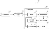
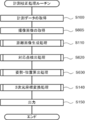
- FIG. 1 is a block diagram illustrating a configuration of a measurement system 10 according to the first embodiment of the present invention.
- the measurement system 10 includes a measurement calibration device 100, a laser measurement device 200, and a measurement database (DB) 300.
- DB measurement database
- the laser measuring device 200 measures, for each of a plurality of points on the object, three-dimensional coordinate data including the three-dimensional coordinates of the point.
- the laser measurement device 200 measures three-dimensional coordinate data of a specific object.
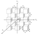
- FIG. 2 a three-dimensional object shown in FIG. 2 is measured as an example of the specific object.
- FIG. 3 shows a front view of the specific object and cross-sectional views in the horizontal direction and the vertical direction.
- rectangular parallelepipeds having a width w, a height h, and a depth d are arranged on the near side at an interval of w in the horizontal direction and at an interval of h in the vertical direction.
- an Xw axis is defined in the horizontal direction
- a Yw axis is defined in the vertical direction
- a Zw axis is defined in a direction orthogonal to the two axes
- the origin is predetermined.
- the XwYwZw coordinate system having the center O of the obtained specific object is set as a world coordinate system (FIG. 2).
- the laser measurement device 200 changes the position and orientation of the specific object and measures the three-dimensional coordinate data of the specific object for each of the S (S is a natural number of 2 or more) position and orientation in the local coordinate system XYZ of the laser measurement device 200. I do.
- the three-dimensional coordinate data includes, for each of a plurality of points on the specific object, the three-dimensional coordinates (X, Y, Z) of the point. It is assumed that the S positions and orientations include a position and orientation as a reference for the specific object.
- the laser measurement device 200 obtains the three-dimensional coordinates of the specific object by using the measurement center of the laser measurement device 200 as the origin and using a local coordinate system set in the laser measurement device.
- the S positions and orientations of the specific object may include those where only the position is changed and those where only the orientation is changed.
- the laser measuring apparatus 200 stores all of the measured three-dimensional coordinate data of the specific object for each of the S positions and orientations in the measurement DB 300.
- the measurement DB 300 includes reference coordinates, which are three-dimensional coordinates of each point in the world coordinate system at a position and orientation serving as a reference of the specific object, and three-dimensional coordinate data of the specific object measured by the laser measurement device 200, 3D coordinate data for each of the S positions and orientations in the local coordinate system XYZ are stored.
- the measurement DB 300 stores reference coordinates, which are three-dimensional coordinates of each point on the specific object in the world coordinate system, obtained from the three-dimensional coordinate data of the specific object at the reference position and orientation.
- the measurement and calibration apparatus 100 is configured by a computer including a CPU, a RAM, and a ROM that stores a program for executing a measurement and calibration processing routine to be described later, and is functionally configured as follows. .
- the measurement and calibration device 100 includes an acquisition unit 110, a distance image generation unit 120, a corresponding point detection unit 130, a posture / position calculation unit 140, and a three-dimensional coordinate conversion unit. 150 and an output unit 160.
- the acquisition unit 110 obtains, from the measurement DB 300, reference coordinates that are three-dimensional coordinates of each point in the world coordinate system at a position and orientation serving as a reference of the specific object, and S position and orientation measured by the laser measurement device 200. Acquire three-dimensional coordinate data of a specific object.
- the acquisition unit 110 then sends the three-dimensional coordinate data for each of the S positions and orientations measured by the laser measurement device 200 to the distance image generation unit 120, the reference coordinates of the specific object to the orientation / position calculation unit 140, and the specific object And the three-dimensional coordinate data for each of the S positions and orientations measured by the laser measuring device 200 are passed to the three-dimensional coordinate conversion unit 150.
- the distance image generation unit 120 calculates the distance to the specific object for each of the S positions and postures based on the three-dimensional coordinate data of the specific object for each of the S positions and postures obtained by the laser measurement device 200. Generate a distance image to represent.
- distance image generation section 120 first sets parameter f for generating a distance image.
- the distance image generation unit 120 generates a distance image for each of the S position and orientation obtained by the laser measurement device 200, based on the three-dimensional coordinate data of the position and orientation.
- the distance image is an image representing the distance to the object, and is a perspective projection image in which the depth distance is visualized in black and white shading or the like.
- Equation (1) corresponds to perspective projection of the camera, and the parameter f corresponds to the focal length of the range image.
- the distance image generation unit 120 calculates the distance L from the laser measurement device to each point using the following equation (2), and quantizes the value from a value 0 to a value 255 according to the value of the distance L. A gray value g of the distance image is calculated.
- the gray value g of v) is calculated.
- the distance image generation unit 120 similarly calculates the gray value g of the two-dimensional coordinate data (u, v) for all three-dimensional coordinates (X, Y, Z) included in the three-dimensional coordinate data of the position and orientation. Thereby, a distance image representing the distance to the specific object in the three-dimensional coordinate data of the position and orientation is generated.
- the distance image generation unit 120 generates a distance image for each of the other position and orientation based on the three-dimensional coordinate data of the position and orientation. That is, distance image generating section 120 obtains S distance images shown in FIG.
- the distance image generation unit 120 passes the distance images for each of the S positions and orientations to the corresponding point detection unit 130.
- the corresponding point detection unit 130 detects, for each of the distance images for each of the plurality of positions and orientations generated by the distance image generation unit 120, a corner point where the shading of the distance image changes, and performs correspondence between the distance images.
- the corresponding point which is the corner point to be detected is detected.
- the corresponding point detection unit 130 first detects black and white corner points of the first distance image.
- FIG. 5 shows an example of corner point detection.
- ⁇ ⁇ In an example of camera calibration using a two-dimensional plane pattern known in Non-Patent Document 3, such a black and white image is used.
- the corresponding point detection unit 130 detects corner points using a conventional image processing method by converting the three-dimensional coordinate data into a distance image.
- the corresponding point detection unit 130 passes all detected corresponding points to the posture / position calculation unit 140.
- the posture / position calculation unit 140 calculates the two-dimensional coordinates of each point on the world coordinate system and the distance image on the distance image based on the corresponding point in each distance image and the reference coordinates of a point on the specific object corresponding to the corresponding point.
- a plane projection transformation matrix for performing plane projection transformation between two-dimensional coordinates and the plane projection transformation matrix ,
- the position and orientation of the local coordinate system XYZ which is a unique coordinate system of the laser measurement device 200 with respect to the world coordinate system, are calculated.
- the posture / position calculation unit 140 firstly sets the reference coordinates (Xw, Yw, Yw, Yw, Yw, Zw), two-dimensional coordinates (Xw, Yw) of each point in the world coordinate system are obtained.
- the posture / position calculation unit 140 calculates the two-dimensional coordinates (u, v) of the corresponding points in each distance image and the two-dimensional coordinates (Xw of the reference coordinates) among the corresponding points obtained by the corresponding point detection unit 130. , Yw) to the plane projection transformation matrix Ask for.
- a two-dimensional coordinate (u, v) of the corresponding point obtained by the corresponding point detection unit 130 and a two-dimensional coordinate (Xw, Yw) of the reference coordinate have a relationship of plane-projection transformation (plane-homography). That's why.
- Plane projection transformation is perspective projection of a plane object given by the following equation (3), as shown in Non-Patent Document 3.
- ⁇ is a scale factor
- H is a 3 ⁇ 3 plane projective transformation matrix
- the posture / position calculation unit 140 calculates the plane projection transformation matrix for performing the plane projection transformation according to Expression (3). Is estimated.
- the posture / position calculator 140 calculates the estimated plane projection transformation matrix.
- the orientation of the local coordinate system with respect to the world The origin of the local coordinate system with respect to the world coordinate system
- Rotation matrix I is a 3 ⁇ 3 matrix, and is expressed as the following equation (4) using three-dimensional vectors r 1 , r 2 , and r 3 .
- Plane transformation matrix Rotation matrix
- Three-dimensional translation vector Has the following relationship (5) in the plane projection transformation relationship.
- the posture / position calculation unit 140 calculates the three-dimensional vectors r 1 and r 2 constituting the rotation matrix and the three-dimensional translation vector Is calculated by the following equation (6).
- the posture / position calculator 140 calculates the rotation matrix Another vector r 3 constituting the, determined by the following equation (7).
- equation (7) Represents the cross product of vectors.
- the posture / position calculator 140 calculates the calculated rotation matrix.
- the three-dimensional coordinate conversion unit 150 calculates the three-dimensional coordinates newly measured by the laser measurement device 200 based on the position and orientation of the laser measurement device 200 in the local coordinate system with respect to the world coordinate system calculated by the orientation / position calculation unit 140. Convert the data to the world coordinate system.
- the three-dimensional coordinate conversion unit 150 is a rotation matrix that indicates the position and orientation of the local coordinate system of the laser measurement device 200 with respect to the world coordinate system calculated by the orientation / position calculation unit 140 , And three-dimensional translation vector Is used to convert the three-dimensional coordinates (X, Y, Z) of the three-dimensional coordinate data measured by the laser measurement device 200 into three-dimensional coordinates (Xw, Yw, Zw) in the world coordinate system.
- the three-dimensional coordinate conversion unit 150 passes the three-dimensional coordinate data measured by the laser measurement device 200 converted to the world coordinate system to the output unit 160.
- the output unit 160 outputs the three-dimensional coordinate data measured by the laser measurement device 200 converted into the world coordinate system.
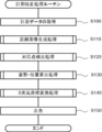
- FIG. 6 is a flowchart illustrating a measurement calibration processing routine according to the embodiment of the present invention.
- the three-dimensional coordinate data of the specific object in each of the S positions and orientations in the local coordinate system XYZ of the laser measurement device 200 is measured by the laser measurement device 200 while changing the position and orientation of the specific object.
- the measurement calibration apparatus 100 executes a measurement calibration processing routine shown in FIG.
- step S100 the acquisition unit 110 acquires three-dimensional coordinate data for each of the S positions and orientations measured by the laser measurement device 200.
- reference coordinates which are three-dimensional coordinates of each point on the specific object in the world coordinate system, are obtained from the three-dimensional coordinate data of the specific object at the reference position and orientation.
- step S110 the distance image generation unit 120 generates the specific object for each of the S positions and postures based on the three-dimensional coordinate data of the specific object for each of the S positions and postures obtained by the laser measurement device 200. Generate a distance image representing the distance to.
- step S120 the corresponding point detection unit 130 detects, for each of the distance images for each of the plurality of positions and orientations generated in step S110, a corner point at which the shading of the distance image changes, and determines the distance between the distance images.
- the corresponding point which is the corresponding corner point is detected.
- step S130 the posture / position calculation unit 140 calculates the two-dimensional coordinates and distance of each point in the world coordinate system based on the corresponding point in each distance image and the reference coordinates of the point of the specific object corresponding to the corresponding point.
- a plane projection transformation matrix for performing plane projection transformation between two-dimensional coordinates on an image and the plane projection transformation matrix , are calculated.
- step S140 the three-dimensional coordinate conversion unit 150 uses the three-dimensional coordinates newly measured by the laser measurement device 200 based on the position and orientation of the local coordinate system of the laser measurement device 200 with respect to the world coordinate system calculated in step S130. Convert the coordinate data to the world coordinate system.
- step S150 the output unit 160 outputs the three-dimensional coordinate data measured by the laser measurement device 200 converted into the world coordinate system.
- step S110 the distance image generation processing routine in step S110 will be described with reference to FIG.
- step S200 distance image generating section 120 sets parameter f for generating a distance image.
- step S210 the distance image generation unit 120 selects the first three-dimensional coordinate data from the three-dimensional coordinate data of the specific object for each of the S positions and orientations obtained by the laser measurement device 200.
- step S220 the distance image generation unit 120 calculates the two-dimensional coordinates (u, v) from the three-dimensional coordinates (X, Y, Z) of each point of the selected three-dimensional coordinate data using the above equation (1). ) Is calculated.
- step S230 the distance image generation unit 120 calculates a distance L to each point of the three-dimensional coordinate data selected from the laser measurement device using the above equation (2), and calculates a value according to the value of the distance L.
- the gray value g of the distance image is calculated by quantizing from 0 to a value of 255.
- step S240 the distance image generation unit 120 determines whether all three-dimensional coordinate data has been processed.
- step S250 distance image generation section 120 selects the next three-dimensional coordinate data, and returns to step S220.
- step S240 if all three-dimensional coordinate data has been processed (YES in step S240), the process returns.
- step S120 the corresponding point detection processing routine in step S120 will be described with reference to FIG.
- step S300 the corresponding point detection unit 130 selects the first distance image from the distance images for each of the plurality of positions and orientations generated in step S110.
- step S310 the corresponding point detection unit 130 detects a corner point of the selected distance image.
- step S320 the corresponding point detection unit 130 checks whether or not the corner point corresponds to the corner point detected in the distance image in which the corner point has already been detected. .
- step S330 the corresponding point detection unit 130 determines whether or not all the distance images have been processed.
- step S340 the corresponding point detection unit 130 selects the next distance image and returns to step S310.
- step S330 if all the distance images have been processed (YES in step S330), the process returns.
- the posture / position calculation unit 140 calculates the two-dimensional coordinates of each point in the world coordinate system and the distance image on the distance image based on the corresponding point in each distance image and the reference coordinates of each point on the specific object corresponding to the corresponding point.
- Projection transformation matrix for projective transformation between two-dimensional coordinates and the plane projection transformation matrix ,
- the position and orientation of the local coordinate system XYZ which is a unique coordinate system of the laser measurement device 200 with respect to the world coordinate system, are calculated.
- step S400 for each corresponding point, the posture / position calculation unit 140 acquires the reference coordinates of a point on the specific object corresponding to the corresponding point.
- step S410 the posture / position calculation unit 140 determines the two-dimensional coordinates of each point in the world coordinate system and the distance image based on each corresponding point and the reference coordinates of a point on the specific object corresponding to the corresponding point. Projection transformation matrix for performing plane projection transformation between two-dimensional coordinates of Is calculated.
- step S420 the posture / position calculator 140 calculates the plane projection transformation matrix calculated in step S410.
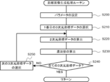
- step S140 the three-dimensional coordinate conversion processing routine in step S140 will be described with reference to FIG.
- the three-dimensional coordinate conversion unit 150 converts the three-dimensional coordinate data newly measured by the laser measurement device 200 based on the position and orientation of the local coordinate system of the laser measurement device 200 with respect to the world coordinate system calculated in step S130. Convert to world coordinate system.
- step S500 the three-dimensional coordinate conversion unit 150 selects the first three-dimensional coordinate data from the three-dimensional coordinate data of the specific object for each of the S positions and orientations obtained by the laser measurement device 200.
- step S510 the three-dimensional coordinate conversion unit 150 converts the selected three-dimensional coordinate data into world coordinates based on the position and orientation of the laser measurement device 200 in the local coordinate system with respect to the world coordinate system calculated in step S130. Convert to system.
- step S520 the three-dimensional coordinate conversion unit 150 determines whether to stop the process.
- step S530 the three-dimensional coordinate conversion unit 150 selects the next three-dimensional coordinate data, and returns to step S510.
- step S520 if all three-dimensional coordinate data has been processed (YES in step S520), the process returns.
- the three-dimensional coordinate data of the specific object obtained by the laser measurement device Based on the coordinate data, a distance image representing a distance to a specific object is generated for each of the plurality of position / postures. For each of the distance images for each of the plurality of position / postures, a corner at which the shading of the distance image changes Detecting a point, detecting a corresponding point that is a corner point corresponding between the distance images, and calculating the detected corresponding point and three-dimensional coordinate data at a reference position and orientation among a plurality of positions and orientations.
- Two-dimensional coordinates of each point in the world coordinate system based on reference coordinates of points on the specific object corresponding to the corresponding point among reference coordinates that are three-dimensional coordinates of each point on the specific object in the world coordinate system. And on the distance image A plane projection transformation matrix for performing plane projection transformation with the dimensional coordinates is calculated, and the position and orientation of the local coordinate system, which is a unique coordinate system of the laser measurement apparatus with respect to the world coordinate system, based on the plane projection transformation matrix. , The position and orientation of the local coordinate system in the laser measurement device with respect to the world coordinate system can be easily estimated.
- FIG. 11 is a block diagram showing the configuration of the measurement system 20 according to the second embodiment of the present invention.
- the measurement and calibration device 500 calibrates both the laser measurement device 200 and the imaging device 400.
- the measurement system 10 includes a laser measurement device 200, a measurement database (DB) 310, an imaging device 400, and a measurement calibration device 500.
- DB measurement database
- a three-dimensional object shown in FIG. 12 is measured as an example of the specific object.
- the front view of the specific object and the cross-sectional views in the horizontal direction and the vertical direction are the same as those in FIG. 3, but in the specific object, the front surface is black, and the other surfaces such as the back surface are It is white.
- the specific object has a rectangular parallelepiped having a width w, a height h, and a depth d on the near side arranged at an interval of w in the horizontal direction and an interval of h in the vertical direction, and has a front surface when viewed from the front.
- the object has a checkerboard shape.
- an Xw axis is defined in the horizontal direction
- a Yw axis is defined in the vertical direction
- a Zw axis is defined in a direction orthogonal to the two axes
- the origin is set at the center of the specific object.
- the XwYwZw coordinate system set to O is set as the world coordinate system (FIG. 12).
- the imaging device 400 changes the position and orientation of the specific object, shoots the specific object with a camera or the like, and generates S captured images.
- S which is the number of positions and orientations, may be a value different from that of the laser measurement device 200.
- the imaging device 400 stores the generated S captured images in the measurement DB 310.
- the measurement DB 310 is, similarly to the measurement DB 300 according to the first embodiment, three-dimensional coordinate data of a specific object measured by the laser measurement device 200, and is provided for each of S positions and orientations in the local coordinate system XYZ.
- the three-dimensional coordinate data is stored.
- the measurement DB 310 stores reference coordinates, which are three-dimensional coordinates of each point on the specific object in the world coordinate system, obtained from the three-dimensional coordinate data of the specific object at the reference position and orientation.
- the measurement DB 310 further stores captured images for each of the S positions and orientations obtained by the imaging device 400.
- the measurement and calibration device 500 is configured by a computer including a CPU, a RAM, and a ROM that stores a program for executing a measurement and calibration processing routine to be described later, and is functionally configured as follows. .
- the measurement calibration device 500 includes a captured image acquisition unit 510, a distance image generation unit 120, a corresponding point detection unit 530, a posture / position calculation unit 540, and three-dimensional coordinates. It is configured to include a conversion unit 150 and an output unit 560.
- the captured image acquisition unit 510 measures, from the measurement DB 310, reference coordinates that are three-dimensional coordinates of each point in the world coordinate system at a position and orientation that is a reference of the specific object, and measures the laser measurement device 200 The obtained three-dimensional coordinate data of the specific object for each of the S positions and orientations is obtained.
- the captured image acquisition unit 510 acquires a captured image representing a specific object obtained by the imaging device 400 from the measurement DB 310 for each of a plurality of positions and orientations.
- the captured image acquisition unit 510 outputs the three-dimensional coordinate data for each of the S positions and orientations measured by the laser measurement device 200 to the distance image generation unit 120, the reference coordinates of the specific object to the orientation / position calculation unit 540, The reference coordinates of the specific object and the three-dimensional coordinate data for each of the S positions and orientations measured by the laser measurement device 200 are passed to the three-dimensional coordinate conversion unit 150.
- the captured image acquisition unit 510 passes the captured image representing the specific object obtained by the imaging device 400 to the corresponding point detection unit 530.
- the corresponding point detecting unit 530 is, for each of the plurality of distance images generated by the distance image generating unit 120, a corner point at which the shading of the distance image changes. Is detected, and a corresponding point that is a corresponding corner point between the distance images is detected.
- the corresponding point detection unit 530 further detects, for each of the captured images for each of the plurality of positions and orientations, a second corner point at which the pixel value of the captured image changes, and a corresponding second corner between the captured images. A second corresponding point, which is a point, is detected.
- the corresponding point detection unit 530 first detects a second corner point at which the pixel value of the first captured image changes.
- the imaging device 400 captures the three-dimensional object shown in FIG. 12, all the black surfaces can be observed as planar projection images. That is, similarly to the case where the distance image is obtained by the planar projection transformation from the three-dimensional coordinate data in the first embodiment, the imaging device 400 captures a monochrome pattern by the planar projection by imaging observation. Since the back surface is white, the captured image is an image like a checkered pattern shown in FIG.
- the corresponding point detection unit 530 detects the second corner point where the pixel values of black and white of such a captured image change, using a conventional image processing method.
- the corresponding point detection unit 530 similarly detects the second corner point in the next captured image.
- the corresponding point detection unit 530 checks whether or not the second corner point corresponds to the second corner point detected in the previous captured image.
- the corresponding point detection unit 530 performs this process on all the captured images, and among the obtained corresponding points, converts the two-dimensional coordinate data of the corresponding points corresponding to the grid points on the surface of each rectangular parallelepiped of the specific object into the second data. This is the detection result of the corresponding point.
- the corresponding point detection unit 530 passes all the detected corresponding points and the second corresponding points to the posture / position calculation unit 540.
- the posture / position calculation unit 540 like the posture / position calculation unit 140, based on the corresponding point in each distance image and the reference coordinates of a point on the specific object corresponding to the corresponding point, and uses the respective coordinates in the world coordinate system.
- a plane projection transformation matrix for performing plane projection transformation between the two-dimensional coordinates of the point and the two-dimensional coordinates on the range image and the plane projection transformation matrix ,
- the position and orientation of the local coordinate system XYZ which is a unique coordinate system of the laser measurement device 200 with respect to the world coordinate system, are calculated.
- the posture / position calculation unit 540 further calculates, based on the detected second corresponding point and the reference coordinates of a point on the specific object corresponding to the second corresponding point, two points of the world coordinate system.
- Second plane projection transformation matrix for performing plane projection transformation between two-dimensional coordinates and two-dimensional coordinates on a captured image Is calculated, and a second plane projective transformation matrix is calculated.
- the position and orientation of the second local coordinate system which is a unique coordinate system of the imaging device 400 with respect to the world coordinate system, are calculated.
- the posture / position calculation unit 540 determines the two-dimensional coordinates (u, v) of the second corresponding point in each captured image among the second corresponding points obtained by the corresponding point detection unit 530, and the reference coordinates. From the two-dimensional coordinates (Xw, Yw) in accordance with the above equation (3). Is estimated.
- the posture / position calculator 540 calculates the estimated second plane projection transformation matrix.
- the orientation of the local coordinate system with respect to the world The origin of the local coordinate system with respect to the world coordinate system
- Rotation matrix I is a 3 ⁇ 3 matrix, and is represented as the above equation (4) using three-dimensional vectors r 1 , r 2 , and r 3 .
- the posture / position calculation unit 540 calculates the three-dimensional vectors r 1 and r 2 constituting the rotation matrix and the three-dimensional translation vector based on the relationship of the above equation (5). Are obtained by the above equation (6).
- the posture / position calculation unit 540 calculates the rotation matrix Another vector r 3 constituting the obtained by the equation (7).
- the posture / position calculator 540 calculates the calculated rotation matrix of the laser measurement device 200.
- the posture / position calculation unit 540 calculates the calculated rotation matrix of the imaging device 400. , And three-dimensional translation vector Is passed to the output unit 560.
- the output unit 560 outputs the three-dimensional coordinate data measured by the laser measurement device 200 converted into the world coordinate system. Further, the output unit 560 is a rotation matrix of the imaging device 400. , And three-dimensional translation vector Is output.
- FIG. 13 is a flowchart illustrating a measurement calibration processing routine according to the second embodiment of the present invention. Note that the same processes as those in the measurement calibration process routine according to the first embodiment are denoted by the same reference numerals, and detailed description is omitted.
- the measurement calibration device 500 executes a measurement calibration process routine shown in FIG.
- step S605 the captured image acquisition unit 510 acquires, from the measurement DB 310, a captured image representing the specific object obtained by the imaging device 400.
- the corresponding point detection unit 530 detects, for each of the distance images for each of the plurality of positions and orientations generated in step S110, a corner point where the shading of the distance image changes, and calculates the distance between the distance images.
- a second corner point that is a point at which the pixel value of the captured image changes is detected between the captured images.
- step S630 the posture / position calculation unit 540 determines the two-dimensional coordinates of each point in the world coordinate system based on the corresponding point in each distance image and the reference coordinates of a point on the specific object corresponding to the corresponding point.
- a plane projection transformation matrix for performing plane projection transformation between two-dimensional coordinates on a range image and the plane projection transformation matrix , are calculated.
- the two-dimensional coordinates of each point in the world coordinate system and the two-dimensional coordinates on the captured image are determined.
- Second plane projective transformation matrix for plane projective transformation between Is calculated, and a second plane projective transformation matrix is calculated.
- the position and orientation of the second local coordinate system which is a unique coordinate system of the imaging device 400 with respect to the world coordinate system, are calculated.
- step S620 the corresponding point detection processing routine in step S620 will be described with reference to FIG.
- step S750 the corresponding point detection unit 530 selects the first captured image among the captured images for each of the plurality of positions and orientations acquired in step S605.
- step S760 the corresponding point detection unit 530 detects the second corner point of the selected captured image.
- step S770 the corresponding point detection unit 530 checks whether or not the second corner point corresponds to the second corner point detected in the captured image in which the second corner point has already been detected, and determines whether or not the second corner point has the same position. If there is, it is detected as a second corresponding point.
- step S780 the corresponding point detection unit 530 determines whether or not all the captured images have been processed.
- step S790 the corresponding point detection unit 530 selects the next captured image, and returns to step S760.
- step S780 if all the captured images have been processed (YES in step S780), the process returns.
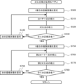
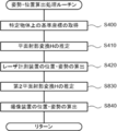
- step S630 the posture / position calculation processing routine in step S630 will be described with reference to FIG.
- step S830 the posture / position calculation unit 540 determines the two-dimensional coordinates of each point in the world coordinate system and the captured image on the basis of the corresponding point and the reference coordinates of a point on the specific object corresponding to the corresponding point. Projection transformation matrix for performing plane projection transformation between two-dimensional coordinates of Is calculated.
- step S840 the posture / position calculation unit 540 calculates the second plane projection transformation matrix calculated in step S830. , The position and orientation of the local coordinate system XYZ, which is a unique coordinate system of the imaging device 400 with respect to the world coordinate system, are calculated, and the process returns.
- a captured image representing a specific object obtained by the imaging device is acquired, and for each of the plurality of For each of the captured images, a second corner point where the pixel value of the captured image changes is detected, and a second corresponding point which is a second corner point corresponding between the captured images is detected and used as a reference.
- a second plane projection transformation matrix for performing plane projection transformation between the two-dimensional coordinates on the captured image is calculated, and based on the second plane projection transformation matrix, a unique coordinate system of the imaging apparatus with respect to the world coordinate system is used.
- the position and orientation of a certain second local coordinate system To exit, the position and orientation of the local coordinate system in the laser measuring device to the world coordinate system with easily estimate the position and orientation of the local coordinate system in the image pickup apparatus can be estimated simultaneously.
- FIG. 16 is a block diagram showing a configuration of a measurement system 30 according to the third embodiment of the present invention.
- the measurement system 30 includes the measurement calibration device 100, N laser measurement devices 200 # 1 to #N, and a measurement database (DB) 320.
- each unit of the measurement and calibration device 100 is the same as when one laser measurement device 200 is used.
- the three-dimensional coordinate data obtained by each laser measurement device 200 is stored in the measurement DB 320 while switching between the laser measurement devices 200 # 1 to 200 # N.
- reference coordinates which are three-dimensional coordinates of each point in the world coordinate system at a position and orientation serving as a reference of a specific object
- the measured three-dimensional coordinate data of the specific object, and three-dimensional coordinate data for each of the S positions and orientations in the local coordinate system XYZ are stored.
- the measurement DB 320 also includes reference coordinates, which are the three-dimensional coordinates of each point on the specific object in the world coordinate system, obtained from the three-dimensional coordinate data of the specific object at the reference position and orientation of each laser measurement device 200. Is stored.
- the three-dimensional object shown in FIG. 2 is used as the specific object, as in the first embodiment.
- the laser measuring devices 200 # 1 to 200 # N are arranged so as to surround the specific object, the three-dimensional object shown in FIG. 17 is used as the specific object.
- the specific object illustrated in FIG. 17 is an object in which rectangular parallelepipeds having a width w, a height h, and a depth d are arranged at intervals of w in the horizontal direction and at intervals of h in the vertical direction. Further, the specific object is configured such that the front surface and the rear surface have the same shape.
- the three-dimensional coordinate data of the specific object obtained by the laser measurement apparatus and the three-dimensional coordinate data of the specific object for each of a plurality of positions and orientations.
- a distance image representing the distance to the specific object is generated, and for each of the plurality of distance and orientation images, a corner point at which the shading of the distance image changes is determined.
- the two-dimensional coordinates and distance of each point on the world coordinate system 2D on the image A plane projection transformation matrix for performing plane projection transformation between the target and the target is calculated, and based on the plane projection transformation matrix, the position and orientation of the local coordinate system, which is a unique coordinate system of the laser measurement device with respect to the world coordinate system, are calculated.
- the three-dimensional coordinate data obtained by each of the plurality of laser measurement devices can be easily synthesized in the world coordinate system.
- FIG. 18 is a block diagram showing a configuration of a measurement system 40 according to the fourth embodiment of the present invention.
- the measurement system 40 includes a measurement / calibration device 500, N laser measurement devices 200 # 1 to #N, a measurement database (DB) 330, and M imaging devices 400 # 1 to #M. .
- each unit of the measurement and calibration device 500 is the same as the case where one laser measurement device 200 is used.
- the three-dimensional coordinates obtained by each laser measurement device 200 are stored in the measurement DB 330 while switching between the laser measurement devices 200 # 1 to 200 # N. Store the data.
- the captured image obtained by each imaging device 400 is stored in the measurement DB 330 while switching between the imaging devices 400 # 1 to 400 # M.
- reference coordinates which are three-dimensional coordinates of each point in the world coordinate system at a position and orientation serving as a reference of a specific object
- the measured three-dimensional coordinate data of the specific object, and three-dimensional coordinate data for each of the S positions and orientations in the local coordinate system XYZ are stored.
- the measurement DB 330 similarly to the measurement DB 320 according to the third embodiment, in the world coordinate system obtained from the three-dimensional coordinate data of the specific object at the reference position and orientation of each laser measurement device 200. Reference coordinates, which are three-dimensional coordinates of each point on the specific object, are stored.
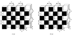
- the three-dimensional object illustrated in FIG. 12 is used as the specific object.
- the laser measurement devices 200 # 1 to 200 # N and the M imaging devices 400 # 1 to #M are arranged so as to surround the specific object, the three-dimensional object shown in FIG. Use an object.
- the specific object shown in FIG. 19 is an object in which rectangular parallelepipeds having a width w, a height h, and a depth d are arranged at intervals of w in the horizontal direction and at intervals of h in the vertical direction.
- the specific object is configured so that the front and the back have the same shape, the front surface is black, and the back surface is white.
- a captured image representing a specific object obtained by the imaging device is acquired, and the captured images of the plurality of positions and orientations are acquired.
- a second corner point which is a point at which the pixel value of the captured image changes, is detected, and a second corresponding point, which is a second corner point corresponding between the captured images, is detected.
- a second plane projection transformation matrix for performing plane projection transformation between the two-dimensional coordinates is calculated, and a second local projection, which is a unique coordinate system of the imaging apparatus with respect to the world coordinate system, is calculated based on the second plane projection transformation matrix.
- the specific object is described on the front side as a rectangular parallelepiped having a width w, a height h, and a depth d arranged at an interval of w in the horizontal direction and at an interval of h in the vertical direction.
- the rectangular parallelepiped may be a cube.
- Data may be transferred between the processing units by using a recording medium such as a hard disk, a RAID device, or a CD-ROM, or by using a remote data resource via a network.
- a recording medium such as a hard disk, a RAID device, or a CD-ROM
- the embodiment has been described in which the program is installed in advance.
- the program may be stored in a computer-readable recording medium and provided.
Abstract
The present invention makes it possible to easily estimate the location and attitude of a local coordinate system for a laser measurement device relative to the world coordinate system. According to the present invention, on the basis of three-dimensional coordinate data for a specific object as in each of a plurality of locations/attitudes, a distance image generation unit 120 generates distance images that represent the distance to the specific object as in the plurality of locations/attitudes. A corresponding point detection unit 130 detects corresponding points that, of corner points that have been detected for each of the distance images for the plurality of locations/attitudes and are points at which the tone of the distance images changes, are points that correspond between distance images. An attitude/location calculation unit 140 calculates the location and attitude of an individual coordinate system for a laser measurement device relative to the world coordinate system on the basis of a matrix that is for a plane projective transformation between two-dimensional coordinates on the distance image for a reference location/attitude and two-dimensional coordinates on the world coordinate system and is calculated on the basis of the corresponding points and of reference coordinates that correspond to the corresponding points from among reference coordinates that are three-dimensional coordinates for each of the points on the specific object on the world coordinate system as found from the three-dimensional coordinate data for the reference location/attitude.
Description
本発明は、計測校正装置、計測校正方法、及びプログラムに係り、特に、世界座標系に対するレーザ計測装置におけるローカル座標系の位置及び姿勢を推定する計測校正装置、計測校正方法、及びプログラムに関する。
The present invention relates to a measurement / calibration apparatus, a measurement / calibration method, and a program, and more particularly, to a measurement / calibration apparatus, a measurement / calibration method, and a program for estimating the position and orientation of a local coordinate system in a laser measurement apparatus with respect to a world coordinate system.
レーザ計測装置(あるいはレンジファインダ装置)は、3次元空間の形状や3次元物体の形状を密な3次元座標データとして獲得することができるセンシングデバイスである。計測仕様の範囲内であれば、人物の形状、室内空間、屋外の景観データ、あるいは市街地の地形データ等を計測することができる。
A laser measuring device (or range finder device) is a sensing device that can acquire the shape of a three-dimensional space or the shape of a three-dimensional object as dense three-dimensional coordinate data. If it is within the range of the measurement specification, it is possible to measure the shape of a person, indoor space, outdoor landscape data, or topographic data of an urban area.
一般的に、レーザ計測装置の内部に3次元座標系(以下、ローカル座標系)が設定され、その座標系において外界の3次元座標(X、Y、Z)を含む3次元座標データが計測される。
Generally, a three-dimensional coordinate system (hereinafter referred to as a local coordinate system) is set inside a laser measuring apparatus, and three-dimensional coordinate data including three-dimensional coordinates (X, Y, Z) of the external world is measured in the coordinate system. You.
複数台のレーザ計測装置(あるいは複数台のレンジファインダ装置)を使って3次元形状のデータを計測するときは、各レーザ計測装置に設置された座標系で3次元座標データが計測される。
When measuring three-dimensional shape data using a plurality of laser measuring devices (or a plurality of range finder devices), three-dimensional coordinate data is measured in a coordinate system installed in each laser measuring device.
このため、統一した3次元座標系(以降、世界座標系)において、それぞれの3次元座標データを合成するあるいは統合する必要がある。従来から、この技術はレジストレーションとして知られている。
Therefore, it is necessary to combine or integrate the respective three-dimensional coordinate data in a unified three-dimensional coordinate system (hereinafter, world coordinate system). Traditionally, this technique is known as registration.
例えば、3次元物体を取り囲むようにレーザ計測装置を配置して、獲得した3次元座標データを世界座標系において合成すると、3次元物体全周囲の密な3次元座標データが得られる。
{For example, when the laser measurement device is arranged so as to surround the three-dimensional object and the acquired three-dimensional coordinate data is combined in the world coordinate system, dense three-dimensional coordinate data around the entire three-dimensional object is obtained.
3次元座標データのレジストレーションには、外界に世界座標系を設置する必要がある。
世界 For registration of three-dimensional coordinate data, it is necessary to set up a world coordinate system in the outside world.
図20にて、レーザ計測装置Aにローカル座標系XYZ、レーザ計測装置Bにローカル座標系X’Y’Z’、外界に世界座標系XwYwZwをそれぞれ設定したとき、世界座標系の3次元座標データを使ってレジストレーションする例を示す。これは基準点測量又は基準点計測と呼ばれている。
In FIG. 20, when the local coordinate system XYZ is set for the laser measurement device A, the local coordinate system X'Y'Z 'is set for the laser measurement device B, and the world coordinate system XwYwZw is set for the outside world, the three-dimensional coordinate data of the world coordinate system is set. Here is an example of registration using. This is called reference point survey or reference point measurement.
まず、世界座標系の3次元座標データ(基準点)を各レーザ計測装置で計測する。次に、レーザ計測装置で得た3次元座標データはローカル座標系で計測されているため、各レーザ計測装置で得たそれぞれの3次元座標データを、世界座標系の3次元座標データへ変換する。
First, three-dimensional coordinate data (reference point) in the world coordinate system is measured by each laser measuring device. Next, since the three-dimensional coordinate data obtained by the laser measuring device is measured in the local coordinate system, each of the three-dimensional coordinate data obtained by each laser measuring device is converted into three-dimensional coordinate data in the world coordinate system. .
測量分野では、このような基準点を使った3次元座標データの合成が用いられている。このときに行われる3次元座標系の変換は、3次元回転変換と平行移動変換とを行う。
合成 In the field of surveying, synthesis of three-dimensional coordinate data using such reference points is used. The conversion of the three-dimensional coordinate system performed at this time includes a three-dimensional rotation conversion and a translation conversion.
非特許文献1には、与えられた基準点の3次元座標データから3次元回転変換と平行移動量を算出する方法が記載されており、非特許文献2には、レーザ計測装置で得た3次元座標に関して正解の3次元形状モデルが与えられることを前提として、獲得した3次元座標データの位置を調整する方法が記載されている。
Non-Patent Document 1 describes a method of calculating a three-dimensional rotation conversion and a translation amount from three-dimensional coordinate data of a given reference point, and Non-Patent Document 2 describes a method of calculating a three-dimensional coordinate obtained by a laser measurement device. A method for adjusting the position of the acquired three-dimensional coordinate data is described on the assumption that a correct three-dimensional shape model is provided for the three-dimensional coordinates.
また、非特許文献3には、2次元平面パターンを使ったキャリブレーション方法が記載されている。
非 Further, Non-Patent Document 3 describes a calibration method using a two-dimensional plane pattern.
レーザ計測装置を常に固定した状態で使用することを前提とすれば、外界に正確な基準点を設置して、その基準点を同定する処理により3次元座標データのレジストレーションを実施できる。
(4) Assuming that the laser measurement device is always used in a fixed state, it is possible to set an accurate reference point in the outside world and register the three-dimensional coordinate data by a process of identifying the reference point.
しかし、獲得した3次元点群データから基準点に該当する1つの3次元座標を正確に抽出する必要があり、専門的なキャリブレーション作業が伴う。
However, it is necessary to accurately extract one three-dimensional coordinate corresponding to a reference point from the acquired three-dimensional point cloud data, which requires a specialized calibration operation.
非特許文献1では、図20に示したように、レーザ計測装置Aとレーザ計測装置Bを使って3次元座標データが測定したとき、片方のローカル座標系(レーザ計測装置Bの3次元座標系)をもう一方のローカル座標系(レーザ計測装置Aの3次元座標系)へ剛体変換する方法が公開されている。
In Non-Patent Document 1, as shown in FIG. 20, when three-dimensional coordinate data is measured using a laser measurement device A and a laser measurement device B, one local coordinate system (the three-dimensional coordinate system of the laser measurement device B) is used. ) Is rigidly transformed into another local coordinate system (the three-dimensional coordinate system of the laser measurement device A).
この剛体変換では、3次元座標系間の3次元回転行列と3次元並進ベクトルとが構成されており、剛体変換によって両レーザ計測装置で測定した3次元座標データが同じ座標系上に合成することができる。
In this rigid transformation, a three-dimensional rotation matrix and a three-dimensional translation vector between the three-dimensional coordinate systems are configured, and the three-dimensional coordinate data measured by the two laser measurement devices is synthesized on the same coordinate system by the rigid transformation. Can be.
片方の3次元座標系からもう一方の3次元座標系への剛体変換は、世界座標系において各ローカル座標系の姿勢と位置とを求めることと等価である。
剛 Rigid body transformation from one three-dimensional coordinate system to another three-dimensional coordinate system is equivalent to obtaining the orientation and position of each local coordinate system in the world coordinate system.
以下、これをレーザ計測のキャリブレーションと呼ぶことにする。
Hereinafter, this will be referred to as laser measurement calibration.
非特許文献1の方法を利用するにあたり、空間中の同一の点をそれぞれレーザ計測装置Aとレーザ計測装置Bとで測定する必要がある。また、当然ながら、正確な剛体変換を求めるためには、1点ではなく100点等と多くの3次元点のペアが必要になる。
In using the method of Non-Patent Document 1, it is necessary to measure the same point in space with the laser measurement device A and the laser measurement device B, respectively. Naturally, in order to obtain an accurate rigid transformation, not only one point but many pairs of three-dimensional points such as 100 points are required.
レーザ計測した3次元座標データの中から、同じ点であるか否かを特定する作業はやや面倒な作業である上に、レーザ計測の空間解像度の限界により、精密に同じ点であることを特定することは容易ではない、という問題があった。
The task of identifying the same point from the three-dimensional coordinate data measured by the laser is a little troublesome, and the exact same point is identified due to the limitation of the spatial resolution of the laser measurement. There is a problem that it is not easy to do.
非特許文献2では、2つの点群データの位置合わせを自動で行うICP(Iterative Closest Point)アルゴリズムが公知となっている。
Non-Patent Document 2 discloses an Iterative Closest Point (ICP) algorithm for automatically aligning two point cloud data.
例えば、まず、レーザ計測装置Bで得た点群を構成する各点に対し、レーザ計測装置Aで得た点群における最近傍点を探索し、これらを仮の対応点とする。次に、これらの対応点間の距離を最小化するような剛体変換を推定する。
{For example, first, for each point constituting the point cloud obtained by the laser measurement device B, the nearest point in the point cloud obtained by the laser measurement device A is searched, and these are set as temporary corresponding points. Next, a rigid transformation that minimizes the distance between these corresponding points is estimated.
ICPアルゴリズムは、対応点探索と剛体変換推定を繰り返すことにより、2つの点群の位置を正確に合わせることができる。
The ICP algorithm can accurately match the positions of two point groups by repeating corresponding point search and rigid body transformation estimation.
ただし、ICPアルゴリズムでは、2つの点群を位置合わせする運動(回転運動と並進運動)が大きいとき、良い初期値を与えないと対応点探索がうまくいかず、ICPアルゴリズムにおいて回転運動と並進運動が局所解に陥る。
However, in the ICP algorithm, when the motion (rotational motion and translational motion) for aligning the two point groups is large, the corresponding point search does not succeed unless a good initial value is given. Fall into a local solution.
このため、レーザ計測のキャリブレーションが不十分となって、2つの点群の位置合わせが不安定になってしまう、という問題があった。
Therefore, there is a problem that the calibration of the laser measurement becomes insufficient and the alignment of the two point groups becomes unstable.
また、レーザ計測装置の台数が新たに増えたり、固定したレーザ計測装置の位置又は姿勢を変更したりする度に、レーザ計測装置のキャリブレーションが必要になる。
Also, every time the number of laser measuring devices is newly increased or the position or orientation of the fixed laser measuring device is changed, calibration of the laser measuring device is required.
本発明は上記の点に鑑みてなされたものであり、世界座標系に対するレーザ計測装置におけるローカル座標系の位置及び姿勢を容易に推定することができる計測校正装置、計測校正方法、及びプログラムを提供することを目的とする。
The present invention has been made in view of the above points, and provides a measurement calibration device, a measurement calibration method, and a program that can easily estimate the position and orientation of a local coordinate system in a laser measurement device with respect to a world coordinate system. The purpose is to do.
本発明に係る計測校正装置は、物体上の複数の点の各々についての前記点の3次元座標を含む3次元座標データを計測するレーザ計測装置によって得られた、特定物体の前記3次元座標データであって、複数の位置姿勢毎の前記特定物体の前記3次元座標データに基づいて、前記複数の位置姿勢毎に、前記特定物体までの距離を表す距離画像を生成する距離画像生成部と、前記距離画像生成部により生成された前記複数の位置姿勢毎の前記距離画像の各々について、前記距離画像の濃淡が変化する点であるコーナー点を検出し、前記距離画像間で対応するコーナー点である対応点を検出する対応点検出部と、前記検出された前記対応点と、前記複数の位置姿勢のうちの基準となる位置姿勢での前記3次元座標データから求められる、世界座標系における前記特定物体上の各点の3次元座標である基準座標のうち、前記対応点に相当する前記特定物体上の点の前記基準座標とに基づいて、前記世界座標系の各点の2次元座標と前記距離画像上の2次元座標との間で平面射影変換するための平面射影変換行列を算出し、前記平面射影変換行列に基づいて、前記世界座標系に対する前記レーザ計測装置の固有の座標系であるローカル座標系の位置及び姿勢を算出する姿勢・位置算出部と、を備えて構成される。
The measuring and calibrating apparatus according to the present invention is characterized in that the three-dimensional coordinate data of a specific object is obtained by a laser measuring apparatus that measures three-dimensional coordinate data including the three-dimensional coordinates of each of a plurality of points on the object. A distance image generation unit that generates a distance image representing a distance to the specific object, for each of the plurality of position and orientation, based on the three-dimensional coordinate data of the specific object for each of a plurality of position and orientation, For each of the distance images for each of the plurality of positions and orientations generated by the distance image generation unit, a corner point that is a point at which the density of the distance image changes is detected, and a corresponding corner point between the distance images is detected. A corresponding point detecting unit that detects a certain corresponding point, the detected corresponding point, and the three-dimensional coordinates obtained from the three-dimensional coordinate data at a reference position and orientation among the plurality of positions and orientations. Of the reference coordinates that are the three-dimensional coordinates of each point on the specific object in the system, based on the reference coordinates of a point on the specific object corresponding to the corresponding point, two points of each point on the world coordinate system are used. A plane projection transformation matrix for performing plane projection transformation between two-dimensional coordinates and two-dimensional coordinates on the distance image is calculated.Based on the plane projection transformation matrix, a unique And a posture / position calculation unit that calculates the position and posture of the local coordinate system, which is a coordinate system.
また、本発明に係る計測校正方法は、距離画像生成部が、物体上の複数の点の各々についての前記点の3次元座標を含む3次元座標データを計測するレーザ計測装置によって得られた、特定物体の前記3次元座標データであって、複数の位置姿勢毎の前記特定物体の前記3次元座標データに基づいて、前記複数の位置姿勢毎に、前記特定物体までの距離を表す距離画像を生成し、対応点検出部が、前記距離画像生成部により生成された前記複数の位置姿勢毎の前記距離画像の各々について、前記距離画像の濃淡が変化する点であるコーナー点を検出し、前記距離画像間で対応するコーナー点である対応点を検出し、姿勢・位置算出部が、前記検出された前記対応点と、前記複数の位置姿勢のうちの基準となる位置姿勢での前記3次元座標データから求められる、世界座標系における前記特定物体上の各点の3次元座標である基準座標のうち、前記対応点に相当する前記特定物体上の点の前記基準座標とに基づいて、前記世界座標系の各点の2次元座標と前記距離画像上の2次元座標との間で平面射影変換するための平面射影変換行列を算出し、前記平面射影変換行列に基づいて、前記世界座標系に対する前記レーザ計測装置の固有の座標系であるローカル座標系の位置及び姿勢を算出する。
Further, in the measurement calibration method according to the present invention, the distance image generation unit is obtained by a laser measurement device that measures three-dimensional coordinate data including three-dimensional coordinates of the plurality of points on the object, A distance image representing the distance to the specific object, for each of the plurality of positions and postures, based on the three-dimensional coordinate data of the specific object for each of the plurality of positions and postures; Generating, the corresponding point detecting unit detects, for each of the distance images for each of the plurality of position and orientation generated by the distance image generating unit, a corner point that is a point at which the shading of the distance image changes, A corresponding point which is a corner point corresponding between the distance images is detected, and a posture / position calculation unit calculates the three-dimensional position in the detected corresponding point and a reference position / posture among the plurality of position / postures. Coordinates Of the three-dimensional coordinates of each point on the specific object in the world coordinate system obtained from the reference coordinates, and the reference coordinates of a point on the specific object corresponding to the corresponding point. A plane projection transformation matrix for performing plane projection transformation between the two-dimensional coordinates of each point of the coordinate system and the two-dimensional coordinates on the distance image is calculated, and based on the plane projection transformation matrix, The position and orientation of a local coordinate system, which is a unique coordinate system of the laser measurement device, are calculated.
本発明に係る計測校正装置及び計測校正方法によれば、距離画像生成部が、物体上の複数の点の各々についての当該点の3次元座標を含む3次元座標データを計測するレーザ計測装置によって得られた、特定物体の3次元座標データであって、複数の位置姿勢毎の特定物体の3次元座標データに基づいて、複数の位置姿勢毎に、特定物体までの距離を表す距離画像を生成し、対応点検出部が、距離画像生成部により生成された複数の位置姿勢毎の距離画像の各々について、当該距離画像の濃淡が変化する点であるコーナー点を検出し、距離画像間で対応するコーナー点である対応点を検出する。
According to the measurement and calibration device and the measurement and calibration method according to the present invention, the distance image generation unit uses a laser measurement device that measures three-dimensional coordinate data including the three-dimensional coordinates of each of a plurality of points on the object. Based on the obtained three-dimensional coordinate data of the specific object, based on the three-dimensional coordinate data of the specific object for each of the plurality of positions and orientations, generate a distance image representing the distance to the specific object for each of the plurality of positions and orientations. Then, for each of the distance images for each of the plurality of positions and orientations generated by the distance image generation unit, the corresponding point detection unit detects a corner point where the shading of the distance image changes, and the correspondence between the distance images is detected. The corresponding point which is the corner point to be detected is detected.
そして、姿勢・位置算出部が、検出された対応点と、複数の位置姿勢のうち基準となる位置姿勢での3次元座標データから求められる、世界座標系における特定物体上の各点の3次元座標である基準座標のうち、当該対応点に相当する特定物体上の点の基準座標とに基づいて、世界座標系の各点の2次元座標と基準となる位置姿勢での距離画像上の2次元座標との間で平面射影変換するための平面射影変換行列を算出し、当該平面射影変換行列に基づいて、世界座標系に対するレーザ計測装置の固有の座標系であるローカル座標系の位置及び姿勢を算出する。
Then, the posture / position calculation unit calculates the three-dimensional position of each point on the specific object in the world coordinate system, which is obtained from the detected corresponding point and three-dimensional coordinate data at a reference position / posture among the plurality of position / postures. Based on the reference coordinates of the points on the specific object corresponding to the corresponding point, the two-dimensional coordinates of each point in the world coordinate system and the two-dimensional coordinates A plane projection transformation matrix for performing plane projection transformation with the dimensional coordinates is calculated, and the position and orientation of the local coordinate system, which is a unique coordinate system of the laser measurement apparatus with respect to the world coordinate system, based on the plane projection transformation matrix. Is calculated.
このように、レーザ計測装置によって得られた、特定物体の3次元座標データであって、複数の位置姿勢毎の特定物体の3次元座標データに基づいて、複数の位置姿勢毎に、特定物体までの距離を表す距離画像を生成し、複数の位置姿勢毎の距離画像の各々について、当該距離画像の濃淡が変化する点であるコーナー点を検出し、距離画像間で対応するコーナー点である対応点を検出し、検出された対応点と、複数の位置姿勢のうちの基準となる位置姿勢での3次元座標データから求められる、世界座標系における特定物体上の各点の3次元座標である基準座標のうち、当該対応点に相当する特定物体上の点の基準座標とに基づいて、世界座標系の各点の2次元座標と距離画像上の2次元座標との間で平面射影変換するための平面射影変換行列を算出し、当該平面射影変換行列に基づいて、世界座標系に対するレーザ計測装置の固有の座標系であるローカル座標系の位置及び姿勢を算出することにより、世界座標系に対するレーザ計測装置におけるローカル座標系の位置及び姿勢を容易に推定することができる。
Thus, based on the three-dimensional coordinate data of the specific object obtained by the laser measurement device and based on the three-dimensional coordinate data of the specific object for each of the plurality of positions and orientations, the specific object is obtained for each of the plurality of positions and orientations. A distance image representing the distance of the distance image is generated, and for each of the distance images for each of the plurality of positions and orientations, a corner point at which the shading of the distance image changes is detected, and a corresponding corner point between the distance images is detected. It is a three-dimensional coordinate of each point on a specific object in the world coordinate system, which is obtained from a detected corresponding point and three-dimensional coordinate data at a reference position and orientation among a plurality of positions and orientations. Based on the reference coordinates of a point on the specific object corresponding to the corresponding point among the reference coordinates, planar projection transformation is performed between the two-dimensional coordinates of each point in the world coordinate system and the two-dimensional coordinates on the distance image. Projective transformation for By calculating the column and calculating the position and orientation of the local coordinate system, which is a unique coordinate system of the laser measurement device with respect to the world coordinate system, based on the plane projection transformation matrix, the local measurement in the laser measurement device with respect to the world coordinate system The position and orientation of the coordinate system can be easily estimated.
また、本発明に係る計測校正装置は、前記姿勢・位置算出部により算出された前記世界座標系に対する前記レーザ計測装置のローカル座標系の位置及び姿勢に基づいて、前記レーザ計測装置が計測した3次元座標データを、前記世界座標系に変換する3次元変換部を更に含むことができる。
In addition, the measurement and calibration device according to the present invention measures the position of the laser measurement device based on the position and orientation of the local measurement system of the laser measurement device with respect to the world coordinate system calculated by the orientation and position calculation unit. The image processing apparatus may further include a three-dimensional conversion unit configured to convert the dimensional coordinate data into the world coordinate system.
また、本発明に係る計測校正装置は、前記複数の位置姿勢毎に、撮像装置により得られた前記特定物体を表す撮像画像を取得する撮像画像取得部を更に含み、前記対応点検出部は、更に、前記複数の位置姿勢毎の前記撮像画像の各々について、前記撮像画像の画素値が変化する点である第2コーナー点を検出し、前記撮像画像間で対応する前記第2コーナー点である第2対応点を検出し、前記姿勢・位置算出部は、更に、前記検出された前記第2対応点と、前記第2対応点に相当する前記特定物体上の点の前記基準座標とに基づいて、前記世界座標系の各点の2次元座標と前記撮像画像上の2次元座標との間での平面射影変換するための第2平面射影変換行列を算出し、前記第2平面射影変換行列に基づいて、前記世界座標系に対する前記撮像装置の固有の座標系である第2ローカル座標系の位置及び姿勢を算出することができる。
In addition, the measurement and calibration device according to the present invention further includes, for each of the plurality of positions and orientations, a captured image acquisition unit that acquires a captured image representing the specific object obtained by an imaging device, and the corresponding point detection unit includes: Further, for each of the captured images for each of the plurality of positions and orientations, a second corner point at which a pixel value of the captured image changes is detected, and a second corner point corresponding to the captured image is detected. A second corresponding point is detected, and the posture / position calculation unit further calculates the second corresponding point based on the detected second corresponding point and the reference coordinates of a point on the specific object corresponding to the second corresponding point. Calculating a second plane projection transformation matrix for performing plane projection transformation between the two-dimensional coordinates of each point in the world coordinate system and the two-dimensional coordinates on the captured image, and calculating the second plane projection transformation matrix Based on the world coordinate system Position and orientation of the second local coordinate system is a unique coordinate system of the image device can be calculated.
また、本発明に係る計測校正装置の前記特定物体は、手前側に、幅w、高さh、奥行きdの直方体が水平方向にwの間隔で配置され、かつ、垂直方向にhの間隔で配置され、正面からみたときに手前側の表面形状が、市松模様状となるように構成することができる。
Further, the specific object of the measurement and calibration apparatus according to the present invention is such that, on the near side, rectangular parallelepipeds having a width w, a height h, and a depth d are arranged at intervals of w in the horizontal direction, and at intervals of h in the vertical direction. It can be configured such that the surface shape on the near side is arranged in a checkered pattern when viewed from the front.
本発明に係るプログラムは、上記の計測校正装置の各部として機能させるためのプログラムである。
プ ロ グ ラ ム A program according to the present invention is a program for functioning as each unit of the above-described measurement and calibration device.
本発明の計測校正装置、計測校正方法、及びプログラムによれば、世界座標系に対するレーザ計測装置におけるローカル座標系の位置及び姿勢を容易に推定することができる。
According to the measurement calibration device, the measurement calibration method, and the program of the present invention, the position and orientation of the local coordinate system in the laser measurement device with respect to the world coordinate system can be easily estimated.
以下、本発明の実施の形態について図面を用いて説明する。
Hereinafter, embodiments of the present invention will be described with reference to the drawings.
<本発明の実施の形態に係る計測校正装置の概要>
まず、本発明の実施の形態の概要について説明する。 <Overview of Measurement Calibration Apparatus According to Embodiment of the Present Invention>
First, an outline of an embodiment of the present invention will be described.
まず、本発明の実施の形態の概要について説明する。 <Overview of Measurement Calibration Apparatus According to Embodiment of the Present Invention>
First, an outline of an embodiment of the present invention will be described.
レーザ計測装置により3次元物体を計測した物体上の複数の点の各々についての3次元座標を含む3次元座標データ(ローカル座標系XYZ上の3次元座標の集合)を、2次元座標系の2次元座標データに変換することができる。
The three-dimensional coordinate data (a set of three-dimensional coordinates on the local coordinate system XYZ) including the three-dimensional coordinates for each of a plurality of points on the object obtained by measuring the three-dimensional object by the laser measurement device is stored in the two-dimensional coordinate system It can be converted to dimensional coordinate data.
一方で、当該3次元物体の世界座標系XwYwZw上の座標(xw,yw,zw)には2次元座標(xw,yw)が含まれており、2次元座標{u,v}と2次元座標(xw,yw)との間には平面射影変換の関係がある。
On the other hand, the coordinates of the world coordinate system XwYwZw of the three-dimensional object (x w, y w, z w) in the two-dimensional coordinates (x w, y w) includes a two-dimensional coordinate {u, v There is a relationship of planar projection transformation between} and the two-dimensional coordinates (x w , y w ).
このことに基づき、本発明の実施の形態では、レーザ計測装置により3次元物体を計測した3次元座標データを距離画像に変換する。
Based on this, in the embodiment of the present invention, the three-dimensional coordinate data obtained by measuring the three-dimensional object by the laser measuring device is converted into a distance image.
当該距離画像から3次元物体に対応する点を検出し、距離画像上の対応点の2次元座標と、3次元物体の世界座標系上の2次元座標との平面射影変換行列

を求める。 A point corresponding to a three-dimensional object is detected from the distance image, and a two-dimensional coordinate of a corresponding point on the distance image and a two-dimensional coordinate of the three-dimensional object on a world coordinate system are projected onto a plane.
Ask for.
そして、平面射影変換行列

から、世界座標系に対するローカル座標系の原点位置を表す3次元並進ベクトルT及び世界座標系に対するローカル座標系の姿勢を表す回転行列

を算出する。 And the plane projective transformation matrix
, A three-dimensional translation vector T representing the origin position of the local coordinate system with respect to the world coordinate system and a rotation matrix representing the orientation of the local coordinate system with respect to the world coordinate system
Is calculated.
から、世界座標系に対するローカル座標系の原点位置を表す3次元並進ベクトルT及び世界座標系に対するローカル座標系の姿勢を表す回転行列
を算出する。 And the plane projective transformation matrix
, A three-dimensional translation vector T representing the origin position of the local coordinate system with respect to the world coordinate system and a rotation matrix representing the orientation of the local coordinate system with respect to the world coordinate system
Is calculated.
本発明によれば、特定の3次元物体を計測するだけで世界座標系におけるレーザ計測装置のローカル座標系の位置姿勢を簡単に推定することを可能とする。
According to the present invention, it is possible to easily estimate the position and orientation of the laser measuring device in the local coordinate system in the world coordinate system only by measuring a specific three-dimensional object.
さらに、レーザ計測装置の姿勢又は位置を変更した場合でも、同様の作業を行うことにより、瞬時にレーザ計測装置のローカル座標系の位置姿勢を簡単に推定することを可能とする。
Furthermore, even when the posture or position of the laser measurement device is changed, by performing the same operation, it is possible to easily estimate the position and posture of the laser measurement device in the local coordinate system instantaneously.
また、3次元物体を取り囲むように複数台のレーザ計測装置を使って3次元座標データを獲得するとき、それらの点群データを世界座標系において合成することができ、3次元物体の全周囲形状の3次元座標データを得ることができ、映画製作あるいは番組制作などのコンピュータグラフィックス、更には実環境とのリアルな仮想現実感(virtual reality)や拡張現実感(augmented reality)を生み出すことができる。
Also, when acquiring three-dimensional coordinate data using a plurality of laser measuring devices so as to surround the three-dimensional object, those point cloud data can be synthesized in the world coordinate system, and the entire peripheral shape of the three-dimensional object can be obtained. 3D coordinate data can be obtained, and computer graphics such as movie production or program production, as well as real virtual reality and augmented reality with an actual environment can be produced. .
<本発明の第1の実施の形態に係る計測校正装置の構成>
図1を参照して、本発明の第1の実施の形態に係る計測システム10の構成について説明する。図1は、本発明の第1の実施の形態に係る計測システム10の構成を示すブロック図である。 <Configuration of Measurement and Calibration Apparatus According to First Embodiment of the Present Invention>
The configuration of themeasurement system 10 according to the first embodiment of the present invention will be described with reference to FIG. FIG. 1 is a block diagram illustrating a configuration of a measurement system 10 according to the first embodiment of the present invention.
図1を参照して、本発明の第1の実施の形態に係る計測システム10の構成について説明する。図1は、本発明の第1の実施の形態に係る計測システム10の構成を示すブロック図である。 <Configuration of Measurement and Calibration Apparatus According to First Embodiment of the Present Invention>
The configuration of the
計測システム10は、計測校正装置100と、レーザ計測装置200と、計測データベース(DB)300とを含んで構成される。
The measurement system 10 includes a measurement calibration device 100, a laser measurement device 200, and a measurement database (DB) 300.
レーザ計測装置200は、物体上の複数の点の各々についての当該点の3次元座標を含む3次元座標データを計測する。
The laser measuring device 200 measures, for each of a plurality of points on the object, three-dimensional coordinate data including the three-dimensional coordinates of the point.
具体的には、レーザ計測装置200は、特定物体の3次元座標データを計測する。
Specifically, the laser measurement device 200 measures three-dimensional coordinate data of a specific object.
本実施形態では、特定物体の一例として、図2に示す3次元の物体を計測する。図3に、当該特定物体の正面図、及び水平方向と垂直方向とのそれぞれの断面図を示す。
In the present embodiment, a three-dimensional object shown in FIG. 2 is measured as an example of the specific object. FIG. 3 shows a front view of the specific object and cross-sectional views in the horizontal direction and the vertical direction.
当該特定物体は、手前側に、幅w、高さh、奥行きdの直方体が水平方向にwの間隔、垂直方向にhの間隔で配置され、正面から見たときに手前側の表面形状が、市松模様状となる物体である。
In the specific object, rectangular parallelepipeds having a width w, a height h, and a depth d are arranged on the near side at an interval of w in the horizontal direction and at an interval of h in the vertical direction. , A checkered object.
基準となる位置姿勢での特定物体の正面図において、水平方向にXw軸、垂直方向にYw軸を定義し、その2つの軸に直交する方向にZw軸を定義し、その原点を、あらかじめ定められた特定物体の中心OとしたXwYwZw座標系を世界座標系とする(図2)。
In the front view of the specific object at the reference position and orientation, an Xw axis is defined in the horizontal direction, a Yw axis is defined in the vertical direction, a Zw axis is defined in a direction orthogonal to the two axes, and the origin is predetermined. The XwYwZw coordinate system having the center O of the obtained specific object is set as a world coordinate system (FIG. 2).
レーザ計測装置200は、当該特定物体の位置姿勢を変えて、レーザ計測装置200のローカル座標系XYZにおけるS個(Sは2以上の自然数)の位置姿勢毎の特定物体の3次元座標データを計測する。
The laser measurement device 200 changes the position and orientation of the specific object and measures the three-dimensional coordinate data of the specific object for each of the S (S is a natural number of 2 or more) position and orientation in the local coordinate system XYZ of the laser measurement device 200. I do.
ここで、3次元座標データは、特定物体上の複数の点の各々についての当該点の3次元座標(X,Y,Z)を含む。また、S個の位置姿勢には、特定物体の基準となる位置姿勢が含まれるものとする。
{Here, the three-dimensional coordinate data includes, for each of a plurality of points on the specific object, the three-dimensional coordinates (X, Y, Z) of the point. It is assumed that the S positions and orientations include a position and orientation as a reference for the specific object.
具体的には、レーザ計測装置200は、当該レーザ計測装置200の計測中心を原点とし、レーザ計測装置に設定したローカル座標系により、特定物体の3次元座標を得る。特定物体のS個の位置姿勢は、位置のみ変更したもの、及び姿勢のみ変更したものを含んでもよい。
Specifically, the laser measurement device 200 obtains the three-dimensional coordinates of the specific object by using the measurement center of the laser measurement device 200 as the origin and using a local coordinate system set in the laser measurement device. The S positions and orientations of the specific object may include those where only the position is changed and those where only the orientation is changed.
そして、レーザ計測装置200は、計測したS個の位置姿勢毎の特定物体の3次元座標データの全てを、計測DB300に格納する。
Then, the laser measuring apparatus 200 stores all of the measured three-dimensional coordinate data of the specific object for each of the S positions and orientations in the measurement DB 300.
計測DB300には、特定物体の基準となる位置姿勢での世界座標系における各点の3次元座標である基準座標と、レーザ計測装置200により計測された特定物体の3次元座標データであって、ローカル座標系XYZにおけるS個の位置姿勢毎の3次元座標データとが格納される。また、計測DB300には、基準となる位置姿勢での特定物体の3次元座標データから求められる、世界座標系における特定物体上の各点の3次元座標である基準座標が格納される。
The measurement DB 300 includes reference coordinates, which are three-dimensional coordinates of each point in the world coordinate system at a position and orientation serving as a reference of the specific object, and three-dimensional coordinate data of the specific object measured by the laser measurement device 200, 3D coordinate data for each of the S positions and orientations in the local coordinate system XYZ are stored. The measurement DB 300 stores reference coordinates, which are three-dimensional coordinates of each point on the specific object in the world coordinate system, obtained from the three-dimensional coordinate data of the specific object at the reference position and orientation.
計測校正装置100は、CPUと、RAMと、後述する計測校正処理ルーチンを実行するためのプログラムを記憶したROMとを備えたコンピュータで構成され、機能的には次に示すように構成されている。
The measurement and calibration apparatus 100 is configured by a computer including a CPU, a RAM, and a ROM that stores a program for executing a measurement and calibration processing routine to be described later, and is functionally configured as follows. .
図1に示すように、本実施形態に係る計測校正装置100は、取得部110と、距離画像生成部120と、対応点検出部130と、姿勢・位置算出部140と、3次元座標変換部150と、出力部160とを備えて構成される。
As shown in FIG. 1, the measurement and calibration device 100 according to the present embodiment includes an acquisition unit 110, a distance image generation unit 120, a corresponding point detection unit 130, a posture / position calculation unit 140, and a three-dimensional coordinate conversion unit. 150 and an output unit 160.
取得部110は、計測DB300から、特定物体の基準となる位置姿勢での世界座標系における各点の3次元座標である基準座標、及びレーザ計測装置200により計測されたS個の位置姿勢毎の特定物体の3次元座標データを取得する。
The acquisition unit 110 obtains, from the measurement DB 300, reference coordinates that are three-dimensional coordinates of each point in the world coordinate system at a position and orientation serving as a reference of the specific object, and S position and orientation measured by the laser measurement device 200. Acquire three-dimensional coordinate data of a specific object.
そして、取得部110は、レーザ計測装置200により計測されたS個の位置姿勢毎の3次元座標データを距離画像生成部120に、特定物体の基準座標を姿勢・位置算出部140に、特定物体の基準座標及びレーザ計測装置200により計測されたS個の位置姿勢毎の3次元座標データを3次元座標変換部150にそれぞれ渡す。
The acquisition unit 110 then sends the three-dimensional coordinate data for each of the S positions and orientations measured by the laser measurement device 200 to the distance image generation unit 120, the reference coordinates of the specific object to the orientation / position calculation unit 140, and the specific object And the three-dimensional coordinate data for each of the S positions and orientations measured by the laser measuring device 200 are passed to the three-dimensional coordinate conversion unit 150.
距離画像生成部120は、レーザ計測装置200によって得られた、S個の位置姿勢毎の当該特定物体の3次元座標データに基づいて、S個の位置姿勢毎に、当該特定物体までの距離を表す距離画像を生成する。
The distance image generation unit 120 calculates the distance to the specific object for each of the S positions and postures based on the three-dimensional coordinate data of the specific object for each of the S positions and postures obtained by the laser measurement device 200. Generate a distance image to represent.
具体的には、距離画像生成部120は、まず、距離画像を生成するためのパラメータfを設定する。パラメータfの設定では、パラメータfに予め定めた値を与える(例えば、f=1000とする)。
Specifically, distance image generation section 120 first sets parameter f for generating a distance image. In setting the parameter f, a predetermined value is given to the parameter f (for example, f = 1000).
次に、距離画像生成部120は、レーザ計測装置200により得られたS個の位置姿勢の各々について、当該位置姿勢の3次元座標データに基づいて、距離画像を生成する。距離画像とは、物体までの距離を表す画像であり、奥行きの距離を白黒濃淡等で可視化した透視投影画像である。
Next, the distance image generation unit 120 generates a distance image for each of the S position and orientation obtained by the laser measurement device 200, based on the three-dimensional coordinate data of the position and orientation. The distance image is an image representing the distance to the object, and is a perspective projection image in which the depth distance is visualized in black and white shading or the like.
特定物体のある位置姿勢の3次元座標データの3次元座標(X,Y,Z)から、距離画像上の2次元座標(u,v)を求める計算には、下記式(1)に示す透視投影の式を用いる。
In the calculation for obtaining the two-dimensional coordinates (u, v) on the distance image from the three-dimensional coordinates (X, Y, Z) of the three-dimensional coordinate data of the position and orientation of the specific object, a perspective represented by the following equation (1) is used. Use the projection formula.

レーザ計測装置200をカメラ装置に置き換えて考えると、式(1)はカメラの透視投影に対応し、パラメータfは距離画像の焦点距離に対応する。
When the laser measurement device 200 is replaced with a camera device, Equation (1) corresponds to perspective projection of the camera, and the parameter f corresponds to the focal length of the range image.
次に、距離画像生成部120は、レーザ計測装置から各点までの距離Lを下記式(2)を用いて算出し、距離Lの値に応じて値0から値255へ量子化することにより距離画像の濃淡値gを算出する。
Next, the distance image generation unit 120 calculates the distance L from the laser measurement device to each point using the following equation (2), and quantizes the value from a value 0 to a value 255 according to the value of the distance L. A gray value g of the distance image is calculated.

例えば、式(2)で得られる距離Lの値が小さい値ほど黒(濃淡値g=0)に、大きい値ほど白(濃淡値g=255)に近づくように、2次元座標データ(u,v)の濃淡値gを算出する。
For example, the two-dimensional coordinate data (u, u, g) is such that the smaller the value of the distance L obtained by the equation (2), the closer to black (gray level g = 0) and the larger the value of the distance L, the closer to white (gray level g = 255). The gray value g of v) is calculated.
距離画像生成部120は、当該位置姿勢の3次元座標データに含まれる全ての3次元座標(X,Y,Z)について、同様に2次元座標データ(u,v)の濃淡値gを算出することにより、当該位置姿勢の3次元座標データの特定物体までの距離を表す距離画像を生成する。
The distance image generation unit 120 similarly calculates the gray value g of the two-dimensional coordinate data (u, v) for all three-dimensional coordinates (X, Y, Z) included in the three-dimensional coordinate data of the position and orientation. Thereby, a distance image representing the distance to the specific object in the three-dimensional coordinate data of the position and orientation is generated.
同様に、距離画像生成部120は、他の位置姿勢の各々について、当該位置姿勢の3次元座標データに基づいて、距離画像を生成する。すなわち、距離画像生成部120は、図4に示すS枚の距離画像を得る。
Similarly, the distance image generation unit 120 generates a distance image for each of the other position and orientation based on the three-dimensional coordinate data of the position and orientation. That is, distance image generating section 120 obtains S distance images shown in FIG.
そして、距離画像生成部120は、S個の位置姿勢の各々についての距離画像を、対応点検出部130に渡す。
{Then, the distance image generation unit 120 passes the distance images for each of the S positions and orientations to the corresponding point detection unit 130.
対応点検出部130は、距離画像生成部120により生成された複数の位置姿勢毎の距離画像の各々について、当該距離画像の濃淡が変化する点であるコーナー点を検出し、距離画像間で対応するコーナー点である対応点を検出する。
The corresponding point detection unit 130 detects, for each of the distance images for each of the plurality of positions and orientations generated by the distance image generation unit 120, a corner point where the shading of the distance image changes, and performs correspondence between the distance images. The corresponding point which is the corner point to be detected is detected.
具体的には、対応点検出部130は、まず、1番目の距離画像の白黒濃淡のコーナー点を検出する。コーナー点検出の例を図5に示す。
Specifically, the corresponding point detection unit 130 first detects black and white corner points of the first distance image. FIG. 5 shows an example of corner point detection.
非特許文献3で公知になっている2次元平面パターンを使ったカメラキャリブレーションの例では、このような白黒濃淡の画像が使われている。対応点検出部130は、3次元座標データを距離画像へ変換することにより、従来の画像処理手法を使ってコーナー点を検出する。
で は In an example of camera calibration using a two-dimensional plane pattern known in Non-Patent Document 3, such a black and white image is used. The corresponding point detection unit 130 detects corner points using a conventional image processing method by converting the three-dimensional coordinate data into a distance image.
次に、次の距離画像においても同様のコーナー点を検出する。
Next, a similar corner point is detected in the next distance image.
このとき、先の距離画像で検出したコーナー点に対応するコーナー点かどうかをチェックして、同じ位置のコーナー点であれば、対応点とする。
At this time, it is checked whether or not the corner point corresponds to the corner point detected in the previous distance image, and if the corner point is at the same position, it is determined as a corresponding point.
この処理を全ての距離画像に行い、得られた対応点のうち、特定物体にある各直方体の表面の格子点に相当する対応点の2次元座標データを、対応点の検出結果とする。
処理 This process is performed on all the distance images, and among the obtained corresponding points, two-dimensional coordinate data of the corresponding points corresponding to the grid points on the surface of each rectangular parallelepiped in the specific object is set as the corresponding point detection results.
そして、対応点検出部130は、検出した全ての対応点を、姿勢・位置算出部140に渡す。
Then, the corresponding point detection unit 130 passes all detected corresponding points to the posture / position calculation unit 140.
姿勢・位置算出部140は、各距離画像における対応点と、当該対応点に相当する特定物体上の点の基準座標とに基づいて、世界座標系の各点の2次元座標と距離画像上の2次元座標との間で平面射影変換するための平面射影変換行列

を算出し、平面射影変換行列

に基づいて、世界座標系に対するレーザ計測装置200の固有の座標系であるローカル座標系XYZの位置及び姿勢を算出する。 The posture /position calculation unit 140 calculates the two-dimensional coordinates of each point on the world coordinate system and the distance image on the distance image based on the corresponding point in each distance image and the reference coordinates of a point on the specific object corresponding to the corresponding point. A plane projection transformation matrix for performing plane projection transformation between two-dimensional coordinates
, And the plane projection transformation matrix
, The position and orientation of the local coordinate system XYZ, which is a unique coordinate system of thelaser measurement device 200 with respect to the world coordinate system, are calculated.
を算出し、平面射影変換行列
に基づいて、世界座標系に対するレーザ計測装置200の固有の座標系であるローカル座標系XYZの位置及び姿勢を算出する。 The posture /
, And the plane projection transformation matrix
, The position and orientation of the local coordinate system XYZ, which is a unique coordinate system of the
具体的には、姿勢・位置算出部140は、まず、特定物体の基準となる位置姿勢での世界座標系XwYwZwにおける各点(各格子点)の3次元座標である基準座標(Xw,Yw,Zw)から、世界座標系の各点の2次元座標(Xw,Yw)を求める。
Specifically, the posture / position calculation unit 140 firstly sets the reference coordinates (Xw, Yw, Yw, Yw, Yw, Zw), two-dimensional coordinates (Xw, Yw) of each point in the world coordinate system are obtained.
より具体的には、図2で示されているように、特定物体の各直方体の幅wと高さhの値に応じて、各格子点に相当する3次元座標(Xw,Yw,0)を得る。すなわち、各格子点は、Zw=0の平面とみなす。
More specifically, as shown in FIG. 2, three-dimensional coordinates (Xw, Yw, 0) corresponding to each grid point according to the values of the width w and the height h of each rectangular parallelepiped of the specific object. Get. That is, each lattice point is regarded as a plane of Zw = 0.
次に、姿勢・位置算出部140は、対応点検出部130により得られた対応点のうち、各距離画像における対応点の2次元座標(u,v)と、基準座標の2次元座標(Xw,Yw)から平面射影変換行列

を求める。 Next, the posture /position calculation unit 140 calculates the two-dimensional coordinates (u, v) of the corresponding points in each distance image and the two-dimensional coordinates (Xw of the reference coordinates) among the corresponding points obtained by the corresponding point detection unit 130. , Yw) to the plane projection transformation matrix
Ask for.
を求める。 Next, the posture /
Ask for.
対応点検出部130により得られた対応点の2次元座標(u,v)と、基準座標の2次元座標(Xw,Yw)の間には、平面射影変換(plane-homography)の関係が成り立つためである。
A two-dimensional coordinate (u, v) of the corresponding point obtained by the corresponding point detection unit 130 and a two-dimensional coordinate (Xw, Yw) of the reference coordinate have a relationship of plane-projection transformation (plane-homography). That's why.
平面射影変換とは、非特許文献3で示されているように、下記式(3)で与えられる平面物体の透視投影である。
Plane projection transformation is perspective projection of a plane object given by the following equation (3), as shown in Non-Patent Document 3.
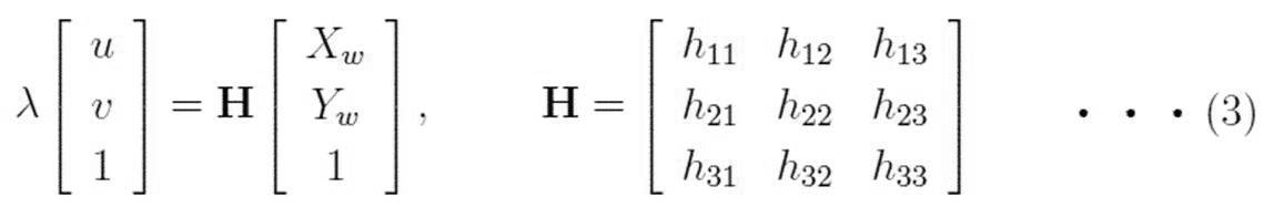
上記式(3)において、λはスケール係数であり、Hは3×3の平面射影変換行列である。
に お い て In the above equation (3), λ is a scale factor, and H is a 3 × 3 plane projective transformation matrix.
上述したように、姿勢・位置算出部140は、式(3)に従って、平面射影変換をするための平面射影変換行列

を推定する。 As described above, the posture /position calculation unit 140 calculates the plane projection transformation matrix for performing the plane projection transformation according to Expression (3).
Is estimated.
を推定する。 As described above, the posture /
Is estimated.
次に、姿勢・位置算出部140は、推定した平面射影変換行列

に基づいて、世界座標系に対するレーザ計測装置200の固有の座標系であるローカル座標系XYZの位置及び姿勢を算出する Next, the posture /position calculator 140 calculates the estimated plane projection transformation matrix.
, The position and orientation of the local coordinate system XYZ, which is a unique coordinate system of thelaser measurement device 200 with respect to the world coordinate system, are calculated.
に基づいて、世界座標系に対するレーザ計測装置200の固有の座標系であるローカル座標系XYZの位置及び姿勢を算出する Next, the posture /
, The position and orientation of the local coordinate system XYZ, which is a unique coordinate system of the
本実施形態では、世界座標系に対するローカル座標系の姿勢を回転行列

、世界座標系に対するローカル座標系の原点位置を3次元並進ベクトル

とする。 In the present embodiment, the orientation of the local coordinate system with respect to the world
, The origin of the local coordinate system with respect to the world coordinate system
And
、世界座標系に対するローカル座標系の原点位置を3次元並進ベクトル
とする。 In the present embodiment, the orientation of the local coordinate system with respect to the world
, The origin of the local coordinate system with respect to the world coordinate system
And
回転行列

は、3×3の行列であり、3次元ベクトルr1,r2,r3を用いて下記式(4)として表される。 Rotation matrix
Is a 3 × 3 matrix, and is expressed as the following equation (4) using three-dimensional vectors r 1 , r 2 , and r 3 .
は、3×3の行列であり、3次元ベクトルr1,r2,r3を用いて下記式(4)として表される。 Rotation matrix
Is a 3 × 3 matrix, and is expressed as the following equation (4) using three-dimensional vectors r 1 , r 2 , and r 3 .

平面射影変換行列

、回転行列

、及び3次元並進ベクトル

は、平面射影変換の関係において、下記(5)の関係を有する。 Plane transformation matrix
, Rotation matrix
, And three-dimensional translation vector
Has the following relationship (5) in the plane projection transformation relationship.
、回転行列
、及び3次元並進ベクトル
は、平面射影変換の関係において、下記(5)の関係を有する。 Plane transformation matrix
, Rotation matrix
, And three-dimensional translation vector
Has the following relationship (5) in the plane projection transformation relationship.

姿勢・位置算出部140は、上記式(5)の関係に基づいて、回転行列を構成する3次元ベクトルr1及びr2と、3次元並進ベクトル

とを、下記式(6)により求める。 The posture /position calculation unit 140 calculates the three-dimensional vectors r 1 and r 2 constituting the rotation matrix and the three-dimensional translation vector
Is calculated by the following equation (6).
とを、下記式(6)により求める。 The posture /
Is calculated by the following equation (6).

また、姿勢・位置算出部140は、回転行列

を構成するもう1つのベクトルr3を、下記式(7)により求める。 In addition, the posture /position calculator 140 calculates the rotation matrix
Another vector r 3 constituting the, determined by the following equation (7).
を構成するもう1つのベクトルr3を、下記式(7)により求める。 In addition, the posture /
Another vector r 3 constituting the, determined by the following equation (7).
ここで、式(7)の

は、ベクトルの外積を表す。 Here, equation (7)
Represents the cross product of vectors.
は、ベクトルの外積を表す。 Here, equation (7)
Represents the cross product of vectors.
そして、姿勢・位置算出部140は、算出した回転行列

、及び3次元並進ベクトル

を、3次元座標変換部150に渡す。 Then, the posture /position calculator 140 calculates the calculated rotation matrix.
, And three-dimensional translation vector
Is passed to the three-dimensional coordinateconversion unit 150.
、及び3次元並進ベクトル
を、3次元座標変換部150に渡す。 Then, the posture /
, And three-dimensional translation vector
Is passed to the three-dimensional coordinate
3次元座標変換部150は、姿勢・位置算出部140により算出された世界座標系に対するレーザ計測装置200のローカル座標系の位置及び姿勢に基づいて、レーザ計測装置200が新たに計測した3次元座標データを、世界座標系に変換する。
The three-dimensional coordinate conversion unit 150 calculates the three-dimensional coordinates newly measured by the laser measurement device 200 based on the position and orientation of the laser measurement device 200 in the local coordinate system with respect to the world coordinate system calculated by the orientation / position calculation unit 140. Convert the data to the world coordinate system.
具体的には、3次元座標変換部150は、姿勢・位置算出部140により算出された世界座標系に対するレーザ計測装置200のローカル座標系の位置及び姿勢を示す回転行列

、及び3次元並進ベクトル

を用いて、レーザ計測装置200が計測した3次元座標データの3次元座標(X,Y,Z)を、世界座標系の3次元座標(Xw,Yw,Zw)に変換する。 Specifically, the three-dimensional coordinateconversion unit 150 is a rotation matrix that indicates the position and orientation of the local coordinate system of the laser measurement device 200 with respect to the world coordinate system calculated by the orientation / position calculation unit 140
, And three-dimensional translation vector
Is used to convert the three-dimensional coordinates (X, Y, Z) of the three-dimensional coordinate data measured by thelaser measurement device 200 into three-dimensional coordinates (Xw, Yw, Zw) in the world coordinate system.
、及び3次元並進ベクトル
を用いて、レーザ計測装置200が計測した3次元座標データの3次元座標(X,Y,Z)を、世界座標系の3次元座標(Xw,Yw,Zw)に変換する。 Specifically, the three-dimensional coordinate
, And three-dimensional translation vector
Is used to convert the three-dimensional coordinates (X, Y, Z) of the three-dimensional coordinate data measured by the
そして、3次元座標変換部150は、世界座標系に変換したレーザ計測装置200が計測した3次元座標データを、出力部160に渡す。
{Circle around (3)}, the three-dimensional coordinate conversion unit 150 passes the three-dimensional coordinate data measured by the laser measurement device 200 converted to the world coordinate system to the output unit 160.
出力部160は、世界座標系に変換したレーザ計測装置200が計測した3次元座標データを出力する。
The output unit 160 outputs the three-dimensional coordinate data measured by the laser measurement device 200 converted into the world coordinate system.
<本発明の第1の実施の形態に係る計測校正装置の作用>
図6は、本発明の実施の形態に係る計測校正処理ルーチンを示すフローチャートである。 <Operation of Measurement and Calibration Device According to First Embodiment of the Present Invention>
FIG. 6 is a flowchart illustrating a measurement calibration processing routine according to the embodiment of the present invention.
図6は、本発明の実施の形態に係る計測校正処理ルーチンを示すフローチャートである。 <Operation of Measurement and Calibration Device According to First Embodiment of the Present Invention>
FIG. 6 is a flowchart illustrating a measurement calibration processing routine according to the embodiment of the present invention.
レーザ計測装置200により、特定物体の位置姿勢を変えながら、レーザ計測装置200のローカル座標系XYZにおけるS個の位置姿勢毎の特定物体の3次元座標データを計測する。取得部110に計測データが入力されると、計測校正装置100において、図6に示す計測校正処理ルーチンが実行される。
(4) The three-dimensional coordinate data of the specific object in each of the S positions and orientations in the local coordinate system XYZ of the laser measurement device 200 is measured by the laser measurement device 200 while changing the position and orientation of the specific object. When the measurement data is input to the acquisition unit 110, the measurement calibration apparatus 100 executes a measurement calibration processing routine shown in FIG.
まず、ステップS100において、取得部110が、レーザ計測装置200により計測されたS個の位置姿勢毎の3次元座標データを取得する。また、基準となる位置姿勢での特定物体の3次元座標データから、世界座標系における特定物体上の各点の3次元座標である基準座標を求める。
First, in step S100, the acquisition unit 110 acquires three-dimensional coordinate data for each of the S positions and orientations measured by the laser measurement device 200. In addition, reference coordinates, which are three-dimensional coordinates of each point on the specific object in the world coordinate system, are obtained from the three-dimensional coordinate data of the specific object at the reference position and orientation.
ステップS110において、距離画像生成部120は、レーザ計測装置200によって得られた、S個の位置姿勢毎の当該特定物体の3次元座標データに基づいて、S個の位置姿勢毎に、当該特定物体までの距離を表す距離画像を生成する。
In step S110, the distance image generation unit 120 generates the specific object for each of the S positions and postures based on the three-dimensional coordinate data of the specific object for each of the S positions and postures obtained by the laser measurement device 200. Generate a distance image representing the distance to.
ステップS120において、対応点検出部130は、上記ステップS110により生成された複数の位置姿勢毎の距離画像の各々について、当該距離画像の濃淡が変化する点であるコーナー点を検出し、距離画像間で対応するコーナー点である対応点を検出する。
In step S120, the corresponding point detection unit 130 detects, for each of the distance images for each of the plurality of positions and orientations generated in step S110, a corner point at which the shading of the distance image changes, and determines the distance between the distance images. The corresponding point which is the corresponding corner point is detected.
ステップS130において、姿勢・位置算出部140は、各距離画像における対応点と、当該対応点に相当する特定物体の点の基準座標とに基づいて、世界座標系の各点の2次元座標と距離画像上の2次元座標との間で平面射影変換するための平面射影変換行列

を算出し、平面射影変換行列

に基づいて、世界座標系に対するレーザ計測装置200の固有の座標系であるローカル座標系XYZの位置及び姿勢を算出する。 In step S130, the posture /position calculation unit 140 calculates the two-dimensional coordinates and distance of each point in the world coordinate system based on the corresponding point in each distance image and the reference coordinates of the point of the specific object corresponding to the corresponding point. A plane projection transformation matrix for performing plane projection transformation between two-dimensional coordinates on an image
, And the plane projection transformation matrix
, The position and orientation of the local coordinate system XYZ, which is a unique coordinate system of thelaser measurement device 200 with respect to the world coordinate system, are calculated.
を算出し、平面射影変換行列
に基づいて、世界座標系に対するレーザ計測装置200の固有の座標系であるローカル座標系XYZの位置及び姿勢を算出する。 In step S130, the posture /
, And the plane projection transformation matrix
, The position and orientation of the local coordinate system XYZ, which is a unique coordinate system of the
ステップS140において、3次元座標変換部150は、上記ステップS130により算出された世界座標系に対するレーザ計測装置200のローカル座標系の位置及び姿勢に基づいて、レーザ計測装置200が新たに計測した3次元座標データを、世界座標系に変換する。
In step S140, the three-dimensional coordinate conversion unit 150 uses the three-dimensional coordinates newly measured by the laser measurement device 200 based on the position and orientation of the local coordinate system of the laser measurement device 200 with respect to the world coordinate system calculated in step S130. Convert the coordinate data to the world coordinate system.
ステップS150において、出力部160は、世界座標系に変換したレーザ計測装置200が計測した3次元座標データを出力する。
In step S150, the output unit 160 outputs the three-dimensional coordinate data measured by the laser measurement device 200 converted into the world coordinate system.
次に、図7を用いて、ステップS110における距離画像生成処理ルーチンについて説明する。
Next, the distance image generation processing routine in step S110 will be described with reference to FIG.
ステップS200において、距離画像生成部120は、距離画像を生成するためのパラメータfを設定する。
距離 In step S200, distance image generating section 120 sets parameter f for generating a distance image.
ステップS210において、距離画像生成部120は、レーザ計測装置200によって得られた、S個の位置姿勢毎の当該特定物体の3次元座標データのうち、1番目の3次元座標データを選択する。
In step S210, the distance image generation unit 120 selects the first three-dimensional coordinate data from the three-dimensional coordinate data of the specific object for each of the S positions and orientations obtained by the laser measurement device 200.
ステップS220において、距離画像生成部120は、上記式(1)を用いて、選択された3次元座標データの各点の3次元座標(X,Y,Z)から、2次元座標(u,v)を計算する。
In step S220, the distance image generation unit 120 calculates the two-dimensional coordinates (u, v) from the three-dimensional coordinates (X, Y, Z) of each point of the selected three-dimensional coordinate data using the above equation (1). ) Is calculated.
ステップS230において、距離画像生成部120は、レーザ計測装置から選択された3次元座標データの各点までの距離Lを、上記式(2)を用いて算出し、距離Lの値に応じて値0から値255へ量子化することにより距離画像の濃淡値gを算出する。
In step S230, the distance image generation unit 120 calculates a distance L to each point of the three-dimensional coordinate data selected from the laser measurement device using the above equation (2), and calculates a value according to the value of the distance L. The gray value g of the distance image is calculated by quantizing from 0 to a value of 255.
ステップS240において、距離画像生成部120は、全ての3次元座標データについて処理したか否かの判定を行う。
In step S240, the distance image generation unit 120 determines whether all three-dimensional coordinate data has been processed.
全ての3次元座標データについて処理していない場合(ステップS240のNO)、ステップS250において、距離画像生成部120は、次の3次元座標データを選択し、ステップS220に戻る。
If all three-dimensional coordinate data has not been processed (NO in step S240), in step S250, distance image generation section 120 selects the next three-dimensional coordinate data, and returns to step S220.
一方、全ての3次元座標データについて処理している場合(ステップS240のYES)、リターンする。
On the other hand, if all three-dimensional coordinate data has been processed (YES in step S240), the process returns.
次に、図8を用いて、ステップS120における対応点検出処理ルーチンについて説明する。
Next, the corresponding point detection processing routine in step S120 will be described with reference to FIG.
ステップS300において、対応点検出部130は、上記ステップS110により生成された複数の位置姿勢毎の距離画像のうち、1番目の距離画像を選択する。
In step S300, the corresponding point detection unit 130 selects the first distance image from the distance images for each of the plurality of positions and orientations generated in step S110.
ステップS310において、対応点検出部130は、選択された距離画像のコーナー点を検出する。
In step S310, the corresponding point detection unit 130 detects a corner point of the selected distance image.
ステップS320において、対応点検出部130は、既にコーナー点を検出した距離画像で検出したコーナー点に対応するコーナー点かどうかをチェックして、同じ位置のコーナー点であれば、対応点として検出する。
In step S320, the corresponding point detection unit 130 checks whether or not the corner point corresponds to the corner point detected in the distance image in which the corner point has already been detected. .
ステップS330において、対応点検出部130は、全ての距離画像について処理したか否かの判定を行う。
In step S330, the corresponding point detection unit 130 determines whether or not all the distance images have been processed.
全ての距離画像について処理していない場合(ステップS330のNO)、ステップS340において、対応点検出部130は、次の距離画像を選択し、ステップS310に戻る。
場合 If all the distance images have not been processed (NO in step S330), in step S340, the corresponding point detection unit 130 selects the next distance image and returns to step S310.
一方、全ての距離画像について処理している場合(ステップS330のYES)、リターンする。
On the other hand, if all the distance images have been processed (YES in step S330), the process returns.
次に、図9を用いて、ステップS130における姿勢・位置算出処理ルーチンについて説明する。姿勢・位置算出部140は、各距離画像における対応点と、当該対応点に相当する特定物体上の各点の基準座標とに基づいて、世界座標系の各点の2次元座標と距離画像上の2次元座標との間で射影変換するための平面射影変換行列

を算出し、平面射影変換行列

に基づいて、世界座標系に対するレーザ計測装置200の固有の座標系であるローカル座標系XYZの位置及び姿勢を算出する。 Next, the posture / position calculation processing routine in step S130 will be described with reference to FIG. The posture /position calculation unit 140 calculates the two-dimensional coordinates of each point in the world coordinate system and the distance image on the distance image based on the corresponding point in each distance image and the reference coordinates of each point on the specific object corresponding to the corresponding point. Projection transformation matrix for projective transformation between two-dimensional coordinates
, And the plane projection transformation matrix
, The position and orientation of the local coordinate system XYZ, which is a unique coordinate system of thelaser measurement device 200 with respect to the world coordinate system, are calculated.
を算出し、平面射影変換行列
に基づいて、世界座標系に対するレーザ計測装置200の固有の座標系であるローカル座標系XYZの位置及び姿勢を算出する。 Next, the posture / position calculation processing routine in step S130 will be described with reference to FIG. The posture /
, And the plane projection transformation matrix
, The position and orientation of the local coordinate system XYZ, which is a unique coordinate system of the
ステップS400において、姿勢・位置算出部140は、各対応点について、当該対応点に相当する特定物体上の点の基準座標を取得する。
In step S400, for each corresponding point, the posture / position calculation unit 140 acquires the reference coordinates of a point on the specific object corresponding to the corresponding point.
ステップS410において、姿勢・位置算出部140は、各対応点と、当該対応点に相当する特定物体上の点の基準座標とに基づいて、世界座標系の各点の2次元座標と距離画像上の2次元座標との間で平面射影変換するための平面射影変換行列

を算出する。 In step S410, the posture /position calculation unit 140 determines the two-dimensional coordinates of each point in the world coordinate system and the distance image based on each corresponding point and the reference coordinates of a point on the specific object corresponding to the corresponding point. Projection transformation matrix for performing plane projection transformation between two-dimensional coordinates of
Is calculated.
を算出する。 In step S410, the posture /
Is calculated.
ステップS420において、姿勢・位置算出部140は、上記ステップS410により算出した平面射影変換行列

に基づいて、世界座標系に対するレーザ計測装置200の固有の座標系であるローカル座標系XYZの位置及び姿勢を算出し、リターンする。 In step S420, the posture /position calculator 140 calculates the plane projection transformation matrix calculated in step S410.
, The position and orientation of the local coordinate system XYZ, which is a unique coordinate system of thelaser measurement device 200 with respect to the world coordinate system, are calculated, and the process returns.
に基づいて、世界座標系に対するレーザ計測装置200の固有の座標系であるローカル座標系XYZの位置及び姿勢を算出し、リターンする。 In step S420, the posture /
, The position and orientation of the local coordinate system XYZ, which is a unique coordinate system of the
次に、図10を用いて、ステップS140における3次元座標変換処理ルーチンについて説明する。
Next, the three-dimensional coordinate conversion processing routine in step S140 will be described with reference to FIG.
3次元座標変換部150は、上記ステップS130により算出された世界座標系に対するレーザ計測装置200のローカル座標系の位置及び姿勢に基づいて、レーザ計測装置200が新たに計測した3次元座標データを、世界座標系に変換する。
The three-dimensional coordinate conversion unit 150 converts the three-dimensional coordinate data newly measured by the laser measurement device 200 based on the position and orientation of the local coordinate system of the laser measurement device 200 with respect to the world coordinate system calculated in step S130. Convert to world coordinate system.
ステップS500において、3次元座標変換部150は、レーザ計測装置200によって得られた、S個の位置姿勢毎の当該特定物体の3次元座標データのうち、1番目の3次元座標データを選択する。
In step S500, the three-dimensional coordinate conversion unit 150 selects the first three-dimensional coordinate data from the three-dimensional coordinate data of the specific object for each of the S positions and orientations obtained by the laser measurement device 200.
ステップS510において、3次元座標変換部150は、上記ステップS130により算出された世界座標系に対するレーザ計測装置200のローカル座標系の位置及び姿勢に基づいて、選択された3次元座標データを、世界座標系に変換する。
In step S510, the three-dimensional coordinate conversion unit 150 converts the selected three-dimensional coordinate data into world coordinates based on the position and orientation of the laser measurement device 200 in the local coordinate system with respect to the world coordinate system calculated in step S130. Convert to system.
ステップS520において、3次元座標変換部150は、処理を停止するか否かの判定を行う。
(4) In step S520, the three-dimensional coordinate conversion unit 150 determines whether to stop the process.
全ての3次元座標データについて処理していない処理を停止しない場合(ステップS520のNO)、ステップS530において、3次元座標変換部150は、次の3次元座標データを選択し、ステップS510に戻る。
If the process that has not been performed on all three-dimensional coordinate data is not stopped (NO in step S520), in step S530, the three-dimensional coordinate conversion unit 150 selects the next three-dimensional coordinate data, and returns to step S510.
一方、全ての3次元座標データについて処理している場合(ステップS520のYES)、リターンする。
On the other hand, if all three-dimensional coordinate data has been processed (YES in step S520), the process returns.
以上説明したように、本発明の実施形態に係る計測校正装置によれば、レーザ計測装置によって得られた、特定物体の3次元座標データであって、複数の位置姿勢毎の特定物体の3次元座標データに基づいて、複数の位置姿勢毎に、特定物体までの距離を表す距離画像を生成し、複数の位置姿勢毎の距離画像の各々について、当該距離画像の濃淡が変化する点であるコーナー点を検出し、距離画像間で対応するコーナー点である対応点を検出し、検出された対応点と、複数の位置姿勢のうちの基準となる位置姿勢での3次元座標データから求められる、世界座標系における特定物体上の各点の3次元座標である基準座標のうち、当該対応点に相当する特定物体上の点の基準座標とに基づいて、世界座標系の各点の2次元座標と距離画像上の2次元座標との間で平面射影変換するための平面射影変換行列を算出し、当該平面射影変換行列に基づいて、世界座標系に対するレーザ計測装置の固有の座標系であるローカル座標系の位置及び姿勢を算出することにより、世界座標系に対するレーザ計測装置におけるローカル座標系の位置及び姿勢を容易に推定することができる。
As described above, according to the measurement and calibration device according to the embodiment of the present invention, the three-dimensional coordinate data of the specific object obtained by the laser measurement device, Based on the coordinate data, a distance image representing a distance to a specific object is generated for each of the plurality of position / postures. For each of the distance images for each of the plurality of position / postures, a corner at which the shading of the distance image changes Detecting a point, detecting a corresponding point that is a corner point corresponding between the distance images, and calculating the detected corresponding point and three-dimensional coordinate data at a reference position and orientation among a plurality of positions and orientations. Two-dimensional coordinates of each point in the world coordinate system based on reference coordinates of points on the specific object corresponding to the corresponding point among reference coordinates that are three-dimensional coordinates of each point on the specific object in the world coordinate system. And on the distance image A plane projection transformation matrix for performing plane projection transformation with the dimensional coordinates is calculated, and the position and orientation of the local coordinate system, which is a unique coordinate system of the laser measurement apparatus with respect to the world coordinate system, based on the plane projection transformation matrix. , The position and orientation of the local coordinate system in the laser measurement device with respect to the world coordinate system can be easily estimated.
また、このような構成により、レーザ計測装置の姿勢又は位置を変更した場合であっても、世界座標系に対するレーザ計測装置におけるローカル座標系の位置及び姿勢を高速に推定することができる。
Also, with such a configuration, even when the posture or position of the laser measurement device is changed, the position and posture of the local coordinate system in the laser measurement device with respect to the world coordinate system can be quickly estimated.
<本発明の第2の実施の形態に係る計測校正装置の構成>
図11を参照して、本発明の第2の実施の形態に係る計測システム20の構成について説明する。なお、第1の実施の形態に係る計測システム10と同様の構成については、同一の符号を付して詳細な説明は省略する。 <Configuration of Measurement and Calibration Apparatus According to Second Embodiment of the Present Invention>
With reference to FIG. 11, the configuration of themeasurement system 20 according to the second embodiment of the present invention will be described. In addition, about the structure similar to the measurement system 10 which concerns on 1st Embodiment, the same code | symbol is attached | subjected and detailed description is abbreviate | omitted.
図11を参照して、本発明の第2の実施の形態に係る計測システム20の構成について説明する。なお、第1の実施の形態に係る計測システム10と同様の構成については、同一の符号を付して詳細な説明は省略する。 <Configuration of Measurement and Calibration Apparatus According to Second Embodiment of the Present Invention>
With reference to FIG. 11, the configuration of the
図11は、本発明の第2の実施の形態に係る計測システム20の構成を示すブロック図である。
FIG. 11 is a block diagram showing the configuration of the measurement system 20 according to the second embodiment of the present invention.
本実施形態では、計測校正装置500は、レーザ計測装置200と撮像装置400とを共に校正する。
In the present embodiment, the measurement and calibration device 500 calibrates both the laser measurement device 200 and the imaging device 400.
計測システム10は、レーザ計測装置200と、計測データベース(DB)310と、撮像装置400と、計測校正装置500とを含んで構成される。
The measurement system 10 includes a laser measurement device 200, a measurement database (DB) 310, an imaging device 400, and a measurement calibration device 500.
本実施形態では、特定物体の一例として、図12に示す3次元の物体を計測する。当該特定物体の正面図、及び水平方向と垂直方向とのそれぞれの断面図は、図3と同様であるが、当該特定物体では、手前の表面は黒色、奥の表面などのそれ以外の表面は白色となっている。
In the present embodiment, a three-dimensional object shown in FIG. 12 is measured as an example of the specific object. The front view of the specific object and the cross-sectional views in the horizontal direction and the vertical direction are the same as those in FIG. 3, but in the specific object, the front surface is black, and the other surfaces such as the back surface are It is white.
また、当該特定物体は、手前側に、幅w、高さh、奥行きdの直方体が水平方向にwの間隔、垂直方向にhの間隔で配置され、正面から見たときに手前側の表面形状が、市松模様状となる物体である。
In addition, the specific object has a rectangular parallelepiped having a width w, a height h, and a depth d on the near side arranged at an interval of w in the horizontal direction and an interval of h in the vertical direction, and has a front surface when viewed from the front. The object has a checkerboard shape.
基準となる位置姿勢における特定物体の正面図において、水平方向にXw軸、垂直方向にYw軸を定義し、その2つの軸に直交する方向にZw軸を定義し、その原点を特定物体の中心OとしたXwYwZw座標系を世界座標系とする(図12)。
In the front view of the specific object at the reference position and orientation, an Xw axis is defined in the horizontal direction, a Yw axis is defined in the vertical direction, a Zw axis is defined in a direction orthogonal to the two axes, and the origin is set at the center of the specific object. The XwYwZw coordinate system set to O is set as the world coordinate system (FIG. 12).
撮像装置400は、レーザ計測装置200と同様に、当該特定物体の位置姿勢を変えて、特定物体をカメラ等で撮影し、S枚の撮像画像を生成する。なお、位置姿勢の数であるSは、レーザ計測装置200と異なる値としてもよい。
Similar to the laser measuring device 200, the imaging device 400 changes the position and orientation of the specific object, shoots the specific object with a camera or the like, and generates S captured images. Note that S, which is the number of positions and orientations, may be a value different from that of the laser measurement device 200.
そして、撮像装置400は、生成したS枚の撮像画像を、計測DB310に格納する。
Then, the imaging device 400 stores the generated S captured images in the measurement DB 310.
計測DB310には、第1の実施の形態に係る計測DB300と同様に、レーザ計測装置200により計測された特定物体の3次元座標データであって、ローカル座標系XYZにおけるS個の位置姿勢毎の3次元座標データとが格納される。また、計測DB310には、基準となる位置姿勢での特定物体の3次元座標データから求められる、世界座標系における特定物体上の各点の3次元座標である基準座標が格納される。
The measurement DB 310 is, similarly to the measurement DB 300 according to the first embodiment, three-dimensional coordinate data of a specific object measured by the laser measurement device 200, and is provided for each of S positions and orientations in the local coordinate system XYZ. The three-dimensional coordinate data is stored. Further, the measurement DB 310 stores reference coordinates, which are three-dimensional coordinates of each point on the specific object in the world coordinate system, obtained from the three-dimensional coordinate data of the specific object at the reference position and orientation.
また、計測DB310には、更に、撮像装置400により得られたS個の位置姿勢毎の撮像画像が格納される。
{Circle around (5)} The measurement DB 310 further stores captured images for each of the S positions and orientations obtained by the imaging device 400.
計測校正装置500は、CPUと、RAMと、後述する計測校正処理ルーチンを実行するためのプログラムを記憶したROMとを備えたコンピュータで構成され、機能的には次に示すように構成されている。
The measurement and calibration device 500 is configured by a computer including a CPU, a RAM, and a ROM that stores a program for executing a measurement and calibration processing routine to be described later, and is functionally configured as follows. .
図11に示すように、本実施形態に係る計測校正装置500は、撮像画像取得部510と、距離画像生成部120と、対応点検出部530と、姿勢・位置算出部540と、3次元座標変換部150と、出力部560とを備えて構成される。
As shown in FIG. 11, the measurement calibration device 500 according to the present embodiment includes a captured image acquisition unit 510, a distance image generation unit 120, a corresponding point detection unit 530, a posture / position calculation unit 540, and three-dimensional coordinates. It is configured to include a conversion unit 150 and an output unit 560.
撮像画像取得部510は、取得部110と同様に、計測DB310から、特定物体の基準となる位置姿勢での世界座標系における各点の3次元座標である基準座標、及びレーザ計測装置200により計測されたS個の位置姿勢毎の特定物体の3次元座標データを取得する。
Similarly to the acquisition unit 110, the captured image acquisition unit 510 measures, from the measurement DB 310, reference coordinates that are three-dimensional coordinates of each point in the world coordinate system at a position and orientation that is a reference of the specific object, and measures the laser measurement device 200 The obtained three-dimensional coordinate data of the specific object for each of the S positions and orientations is obtained.
また、撮像画像取得部510は、複数の位置姿勢毎に、計測DB310から、撮像装置400により得られた特定物体を表す撮像画像を取得する。
(4) The captured image acquisition unit 510 acquires a captured image representing a specific object obtained by the imaging device 400 from the measurement DB 310 for each of a plurality of positions and orientations.
そして、撮像画像取得部510は、レーザ計測装置200により計測されたS個の位置姿勢毎の3次元座標データを距離画像生成部120に、特定物体の基準座標を姿勢・位置算出部540に、特定物体の基準座標及びレーザ計測装置200により計測されたS個の位置姿勢毎の3次元座標データを3次元座標変換部150にそれぞれ渡す。
Then, the captured image acquisition unit 510 outputs the three-dimensional coordinate data for each of the S positions and orientations measured by the laser measurement device 200 to the distance image generation unit 120, the reference coordinates of the specific object to the orientation / position calculation unit 540, The reference coordinates of the specific object and the three-dimensional coordinate data for each of the S positions and orientations measured by the laser measurement device 200 are passed to the three-dimensional coordinate conversion unit 150.
また、撮像画像取得部510は、撮像装置400により得られた特定物体を表す撮像画像を、対応点検出部530に渡す。
(4) The captured image acquisition unit 510 passes the captured image representing the specific object obtained by the imaging device 400 to the corresponding point detection unit 530.
対応点検出部530は、対応点検出部130と同様に、距離画像生成部120により生成された複数の位置姿勢毎の距離画像の各々について、当該距離画像の濃淡が変化する点であるコーナー点を検出し、距離画像間で対応するコーナー点である対応点を検出する。
Similar to the corresponding point detecting unit 130, the corresponding point detecting unit 530 is, for each of the plurality of distance images generated by the distance image generating unit 120, a corner point at which the shading of the distance image changes. Is detected, and a corresponding point that is a corresponding corner point between the distance images is detected.
対応点検出部530は、更に、複数の位置姿勢毎の撮像画像の各々について、当該撮像画像の画素値が変化する点である第2コーナー点を検出し、撮像画像間で対応する第2コーナー点である第2対応点を検出する。
The corresponding point detection unit 530 further detects, for each of the captured images for each of the plurality of positions and orientations, a second corner point at which the pixel value of the captured image changes, and a corresponding second corner between the captured images. A second corresponding point, which is a point, is detected.
具体的には、対応点検出部530は、まず、1番目の撮像画像の画素値が変化する点である第2コーナー点を検出する。
{Specifically, the corresponding point detection unit 530 first detects a second corner point at which the pixel value of the first captured image changes.
図12に示す3次元物体を撮像装置400が撮影すると、黒色の面は全て平面射影の画像として観測することができる。すなわち、第1実施形態において3次元座標データから平面射影変換による距離画像を得た場合と同様に、撮像装置400は、撮像観測によって平面射影による白黒パターンを撮影することとなる。奥の面は白色であるため、撮像画像は図4に示す市松模様のような画像となる。
す る と When the imaging device 400 captures the three-dimensional object shown in FIG. 12, all the black surfaces can be observed as planar projection images. That is, similarly to the case where the distance image is obtained by the planar projection transformation from the three-dimensional coordinate data in the first embodiment, the imaging device 400 captures a monochrome pattern by the planar projection by imaging observation. Since the back surface is white, the captured image is an image like a checkered pattern shown in FIG.
対応点検出部530は、このような撮像画像の黒色と白色との画素値が変化する点である第2コーナー点を、従来の画像処理手法を用いて検出する。
The corresponding point detection unit 530 detects the second corner point where the pixel values of black and white of such a captured image change, using a conventional image processing method.
次に、対応点検出部530は、次の撮像画像においても同様に、第2コーナー点を検出する。
Next, the corresponding point detection unit 530 similarly detects the second corner point in the next captured image.
このとき、対応点検出部530は、先の撮像画像で検出した第2コーナー点に対応する第2コーナー点かどうかをチェックして、同じ位置の第2コーナー点であれば、第2対応点とする。
At this time, the corresponding point detection unit 530 checks whether or not the second corner point corresponds to the second corner point detected in the previous captured image. And
対応点検出部530は、この処理を全ての撮像画像に行い、得られた対応点のうち、特定物体にある各直方体の表面の格子点に相当する対応点の2次元座標データを、第2対応点の検出結果とする。
The corresponding point detection unit 530 performs this process on all the captured images, and among the obtained corresponding points, converts the two-dimensional coordinate data of the corresponding points corresponding to the grid points on the surface of each rectangular parallelepiped of the specific object into the second data. This is the detection result of the corresponding point.
そして、対応点検出部530は、検出した全ての対応点及び第2対応点を、姿勢・位置算出部540に渡す。
対 応 Then, the corresponding point detection unit 530 passes all the detected corresponding points and the second corresponding points to the posture / position calculation unit 540.
姿勢・位置算出部540は、姿勢・位置算出部140と同様に、各距離画像における対応点と、当該対応点に相当する特定物体上の点の基準座標とに基づいて、世界座標系の各点の2次元座標と距離画像上の2次元座標との間で平面射影変換するための平面射影変換行列

を算出し、平面射影変換行列

に基づいて、世界座標系に対するレーザ計測装置200の固有の座標系であるローカル座標系XYZの位置及び姿勢を算出する。 The posture /position calculation unit 540, like the posture / position calculation unit 140, based on the corresponding point in each distance image and the reference coordinates of a point on the specific object corresponding to the corresponding point, and uses the respective coordinates in the world coordinate system. A plane projection transformation matrix for performing plane projection transformation between the two-dimensional coordinates of the point and the two-dimensional coordinates on the range image
, And the plane projection transformation matrix
, The position and orientation of the local coordinate system XYZ, which is a unique coordinate system of thelaser measurement device 200 with respect to the world coordinate system, are calculated.
を算出し、平面射影変換行列
に基づいて、世界座標系に対するレーザ計測装置200の固有の座標系であるローカル座標系XYZの位置及び姿勢を算出する。 The posture /
, And the plane projection transformation matrix
, The position and orientation of the local coordinate system XYZ, which is a unique coordinate system of the
また、姿勢・位置算出部540は、更に、検出された第2対応点と、当該第2対応点に相当する特定物体上の点の基準座標とに基づいて、世界座標系の各点の2次元座標と撮像画像上の2次元座標との間での平面射影変換するための第2平面射影変換行列

を算出し、第2平面射影変換行列

に基づいて、世界座標系に対する撮像装置400の固有の座標系である第2ローカル座標系の位置及び姿勢を算出する。 In addition, the posture /position calculation unit 540 further calculates, based on the detected second corresponding point and the reference coordinates of a point on the specific object corresponding to the second corresponding point, two points of the world coordinate system. Second plane projection transformation matrix for performing plane projection transformation between two-dimensional coordinates and two-dimensional coordinates on a captured image
Is calculated, and a second plane projective transformation matrix is calculated.
, The position and orientation of the second local coordinate system, which is a unique coordinate system of theimaging device 400 with respect to the world coordinate system, are calculated.
を算出し、第2平面射影変換行列
に基づいて、世界座標系に対する撮像装置400の固有の座標系である第2ローカル座標系の位置及び姿勢を算出する。 In addition, the posture /
Is calculated, and a second plane projective transformation matrix is calculated.
, The position and orientation of the second local coordinate system, which is a unique coordinate system of the
具体的には、姿勢・位置算出部540は、対応点検出部530により得られた第2対応点のうち、各撮像画像における第2対応点の2次元座標(u,v)と、基準座標の2次元座標(Xw,Yw)から、上記式(3)に従って、平面射影変換をするための第2平面射影変換行列

を推定する。 Specifically, the posture /position calculation unit 540 determines the two-dimensional coordinates (u, v) of the second corresponding point in each captured image among the second corresponding points obtained by the corresponding point detection unit 530, and the reference coordinates. From the two-dimensional coordinates (Xw, Yw) in accordance with the above equation (3).
Is estimated.
を推定する。 Specifically, the posture /
Is estimated.
次に、姿勢・位置算出部540は、推定した第2平面射影変換行列

に基づいて、世界座標系に対する撮像装置400の固有の座標系であるローカル座標系XYZの位置及び姿勢を算出する Next, the posture /position calculator 540 calculates the estimated second plane projection transformation matrix.
, The position and orientation of the local coordinate system XYZ, which is a unique coordinate system of theimaging device 400 with respect to the world coordinate system, are calculated.
に基づいて、世界座標系に対する撮像装置400の固有の座標系であるローカル座標系XYZの位置及び姿勢を算出する Next, the posture /
, The position and orientation of the local coordinate system XYZ, which is a unique coordinate system of the
本実施形態では、世界座標系に対するローカル座標系の姿勢を回転行列

、世界座標系に対するローカル座標系の原点位置を3次元並進ベクトル

とする。 In the present embodiment, the orientation of the local coordinate system with respect to the world
, The origin of the local coordinate system with respect to the world coordinate system
And
、世界座標系に対するローカル座標系の原点位置を3次元並進ベクトル
とする。 In the present embodiment, the orientation of the local coordinate system with respect to the world
, The origin of the local coordinate system with respect to the world coordinate system
And
回転行列

は、3×3の行列であり、3次元ベクトルr1,r2,r3を用いて上記式(4)として表される。 Rotation matrix
Is a 3 × 3 matrix, and is represented as the above equation (4) using three-dimensional vectors r 1 , r 2 , and r 3 .
は、3×3の行列であり、3次元ベクトルr1,r2,r3を用いて上記式(4)として表される。 Rotation matrix
Is a 3 × 3 matrix, and is represented as the above equation (4) using three-dimensional vectors r 1 , r 2 , and r 3 .
姿勢・位置算出部540は、上記式(5)の関係に基づいて、回転行列を構成する3次元ベクトルr1及びr2と、3次元並進ベクトル

とを、上記式(6)により求める。 The posture /position calculation unit 540 calculates the three-dimensional vectors r 1 and r 2 constituting the rotation matrix and the three-dimensional translation vector based on the relationship of the above equation (5).
Are obtained by the above equation (6).
とを、上記式(6)により求める。 The posture /
Are obtained by the above equation (6).
また、姿勢・位置算出部540は、回転行列

を構成するもう1つのベクトルr3を、上記式(7)により求める。 In addition, the posture /position calculation unit 540 calculates the rotation matrix
Another vector r 3 constituting the obtained by the equation (7).
を構成するもう1つのベクトルr3を、上記式(7)により求める。 In addition, the posture /
Another vector r 3 constituting the obtained by the equation (7).
そして、姿勢・位置算出部540は、算出したレーザ計測装置200の回転行列

、及び3次元並進ベクトル

を、3次元座標変換部150に渡す。 Then, the posture /position calculator 540 calculates the calculated rotation matrix of the laser measurement device 200.
, And three-dimensional translation vector
Is passed to the three-dimensional coordinateconversion unit 150.
、及び3次元並進ベクトル
を、3次元座標変換部150に渡す。 Then, the posture /
, And three-dimensional translation vector
Is passed to the three-dimensional coordinate
また、姿勢・位置算出部540は、算出した撮像装置400の回転行列

、及び3次元並進ベクトル

を、出力部560に渡す。 The posture /position calculation unit 540 calculates the calculated rotation matrix of the imaging device 400.
, And three-dimensional translation vector
Is passed to the output unit 560.
、及び3次元並進ベクトル
を、出力部560に渡す。 The posture /
, And three-dimensional translation vector
Is passed to the output unit 560.
出力部560は、世界座標系に変換したレーザ計測装置200が計測した3次元座標データを出力する。また、出力部560は、撮像装置400の回転行列

、及び3次元並進ベクトル

を出力する。 The output unit 560 outputs the three-dimensional coordinate data measured by thelaser measurement device 200 converted into the world coordinate system. Further, the output unit 560 is a rotation matrix of the imaging device 400.
, And three-dimensional translation vector
Is output.
、及び3次元並進ベクトル
を出力する。 The output unit 560 outputs the three-dimensional coordinate data measured by the
, And three-dimensional translation vector
Is output.
<本発明の第2の実施の形態に係る計測校正装置の作用>
図13は、本発明の第2の実施の形態に係る計測校正処理ルーチンを示すフローチャートである。なお、第1の実施の形態に係る計測校正処理ルーチンと同様の処理については、同一の符号を付して詳細な説明は省略する。 <Operation of Measurement and Calibration Device According to Second Embodiment of the Present Invention>
FIG. 13 is a flowchart illustrating a measurement calibration processing routine according to the second embodiment of the present invention. Note that the same processes as those in the measurement calibration process routine according to the first embodiment are denoted by the same reference numerals, and detailed description is omitted.
レーザ計測装置200により、特定物体の位置姿勢を変えながら、レーザ計測装置200のローカル座標系XYZにおけるS個の位置姿勢毎の特定物体の3次元座標データを計測すると共に、撮像装置400により、S個の位置姿勢毎の特定物体の撮像画像を取得する。計測DB310に計測データ及び撮像画像が格納されると、計測校正装置500において、図13に示す計測校正処理ルーチンが実行される。
While changing the position and orientation of the specific object by the laser measurement device 200, the three-dimensional coordinate data of the specific object for each of the S positions and orientations in the local coordinate system XYZ of the laser measurement device 200 is measured, and the imaging device 400 The captured image of the specific object for each of the position and orientation is acquired. When the measurement data and the captured image are stored in the measurement DB 310, the measurement calibration device 500 executes a measurement calibration process routine shown in FIG.
ステップS605において、撮像画像取得部510は、計測DB310から、撮像装置400により得られた特定物体を表す撮像画像を取得する。
In step S605, the captured image acquisition unit 510 acquires, from the measurement DB 310, a captured image representing the specific object obtained by the imaging device 400.
ステップS620において、対応点検出部530は、上記ステップS110により生成された複数の位置姿勢毎の距離画像の各々について、当該距離画像の濃淡が変化する点であるコーナー点を検出し、距離画像間で対応するコーナー点である対応点を検出すると共に、複数の位置姿勢毎の撮像画像の各々について、当該撮像画像の画素値が変化する点である第2コーナー点を検出し、撮像画像間で対応する第2コーナー点である第2対応点を検出する。
In step S620, the corresponding point detection unit 530 detects, for each of the distance images for each of the plurality of positions and orientations generated in step S110, a corner point where the shading of the distance image changes, and calculates the distance between the distance images. In addition to detecting a corresponding point that is a corresponding corner point in each of the captured images for each of the plurality of positions and orientations, a second corner point that is a point at which the pixel value of the captured image changes is detected between the captured images. A second corresponding point, which is a corresponding second corner point, is detected.
ステップS630において、姿勢・位置算出部540は、各距離画像における対応点と、当該対応点に相当する特定物体上の点の基準座標とに基づいて、世界座標系の各点の2次元座標と距離画像上の2次元座標との間で平面射影変換するための平面射影変換行列

を算出し、平面射影変換行列

に基づいて、世界座標系に対するレーザ計測装置200の固有の座標系であるローカル座標系XYZの位置及び姿勢を算出する。検出された第2対応点と、当該第2対応点に相当する特定物体上の点の基準座標とに基づいて、世界座標系の各点の2次元座標と撮像画像上の2次元座標との間での平面射影変換するための第2平面射影変換行列

を算出し、第2平面射影変換行列

に基づいて、世界座標系に対する撮像装置400の固有の座標系である第2ローカル座標系の位置及び姿勢を算出する。 In step S630, the posture /position calculation unit 540 determines the two-dimensional coordinates of each point in the world coordinate system based on the corresponding point in each distance image and the reference coordinates of a point on the specific object corresponding to the corresponding point. A plane projection transformation matrix for performing plane projection transformation between two-dimensional coordinates on a range image
, And the plane projection transformation matrix
, The position and orientation of the local coordinate system XYZ, which is a unique coordinate system of thelaser measurement device 200 with respect to the world coordinate system, are calculated. Based on the detected second corresponding point and the reference coordinates of the point on the specific object corresponding to the second corresponding point, the two-dimensional coordinates of each point in the world coordinate system and the two-dimensional coordinates on the captured image are determined. Second plane projective transformation matrix for plane projective transformation between
Is calculated, and a second plane projective transformation matrix is calculated.
, The position and orientation of the second local coordinate system, which is a unique coordinate system of theimaging device 400 with respect to the world coordinate system, are calculated.
を算出し、平面射影変換行列
に基づいて、世界座標系に対するレーザ計測装置200の固有の座標系であるローカル座標系XYZの位置及び姿勢を算出する。検出された第2対応点と、当該第2対応点に相当する特定物体上の点の基準座標とに基づいて、世界座標系の各点の2次元座標と撮像画像上の2次元座標との間での平面射影変換するための第2平面射影変換行列
を算出し、第2平面射影変換行列
に基づいて、世界座標系に対する撮像装置400の固有の座標系である第2ローカル座標系の位置及び姿勢を算出する。 In step S630, the posture /
, And the plane projection transformation matrix
, The position and orientation of the local coordinate system XYZ, which is a unique coordinate system of the
Is calculated, and a second plane projective transformation matrix is calculated.
, The position and orientation of the second local coordinate system, which is a unique coordinate system of the
次に、図14を用いて、ステップS620における対応点検出処理ルーチンについて説明する。
Next, the corresponding point detection processing routine in step S620 will be described with reference to FIG.
ステップS750において、対応点検出部530は、上記ステップS605により取得した複数の位置姿勢毎の撮像画像のうち、1番目の撮像画像を選択する。
In step S750, the corresponding point detection unit 530 selects the first captured image among the captured images for each of the plurality of positions and orientations acquired in step S605.
ステップS760において、対応点検出部530は、選択された撮像画像の第2コーナー点を検出する。
In step S760, the corresponding point detection unit 530 detects the second corner point of the selected captured image.
ステップS770において、対応点検出部530は、既に第2コーナー点を検出した撮像画像で検出した第2コーナー点に対応する第2コーナー点かどうかをチェックして、同じ位置の第2コーナー点であれば、第2対応点として検出する。
In step S770, the corresponding point detection unit 530 checks whether or not the second corner point corresponds to the second corner point detected in the captured image in which the second corner point has already been detected, and determines whether or not the second corner point has the same position. If there is, it is detected as a second corresponding point.
ステップS780において、対応点検出部530は、全ての撮像画像について処理したか否かの判定を行う。
In step S780, the corresponding point detection unit 530 determines whether or not all the captured images have been processed.
全ての撮像画像について処理していない場合(ステップS780のNO)、ステップS790において、対応点検出部530は、次の撮像画像を選択し、ステップS760に戻る。
If all the captured images have not been processed (NO in step S780), in step S790, the corresponding point detection unit 530 selects the next captured image, and returns to step S760.
一方、全ての撮像画像について処理している場合(ステップS780のYES)、リターンする。
On the other hand, if all the captured images have been processed (YES in step S780), the process returns.
次に、図15を用いて、ステップS630における姿勢・位置算出処理ルーチンについて説明する。
Next, the posture / position calculation processing routine in step S630 will be described with reference to FIG.
ステップS830において、姿勢・位置算出部540は、各対応点と、当該対応点に相当する特定物体上の点の基準座標とに基づいて、世界座標系の各点の2次元座標と撮像画像上の2次元座標との間で平面射影変換するための平面射影変換行列

を算出する。 In step S830, the posture /position calculation unit 540 determines the two-dimensional coordinates of each point in the world coordinate system and the captured image on the basis of the corresponding point and the reference coordinates of a point on the specific object corresponding to the corresponding point. Projection transformation matrix for performing plane projection transformation between two-dimensional coordinates of
Is calculated.
を算出する。 In step S830, the posture /
Is calculated.
ステップS840において、姿勢・位置算出部540は、上記ステップS830により算出した第2平面射影変換行列

に基づいて、世界座標系に対する撮像装置400の固有の座標系であるローカル座標系XYZの位置及び姿勢を算出し、リターンする。 In step S840, the posture /position calculation unit 540 calculates the second plane projection transformation matrix calculated in step S830.
, The position and orientation of the local coordinate system XYZ, which is a unique coordinate system of theimaging device 400 with respect to the world coordinate system, are calculated, and the process returns.
に基づいて、世界座標系に対する撮像装置400の固有の座標系であるローカル座標系XYZの位置及び姿勢を算出し、リターンする。 In step S840, the posture /
, The position and orientation of the local coordinate system XYZ, which is a unique coordinate system of the
以上説明したように、本発明の実施形態に係る計測校正装置によれば、更に、複数の位置姿勢毎に、撮像装置により得られた特定物体を表す撮像画像を取得し、複数の位置姿勢毎の撮像画像の各々について、当該撮像画像の画素値が変化する点である第2コーナー点を検出し、撮像画像間で対応する第2コーナー点である第2対応点を検出し、基準となる位置姿勢での撮像画像における第2対応点と、第2対応点に相当する特定物体の点の基準座標とに基づいて、世界座標系の各点の2次元座標と基準となる位置姿勢での撮像画像上の2次元座標との間での平面射影変換するための第2平面射影変換行列を算出し、第2平面射影変換行列に基づいて、世界座標系に対する撮像装置の固有の座標系である第2ローカル座標系の位置及び姿勢を算出するため、世界座標系に対するレーザ計測装置におけるローカル座標系の位置及び姿勢を容易に推定すると共に、撮像装置におけるローカル座標系の位置及び姿勢も同時に推定することができる。
As described above, according to the measurement and calibration apparatus according to the embodiment of the present invention, further, for each of a plurality of position and orientation, a captured image representing a specific object obtained by the imaging device is acquired, and for each of the plurality of For each of the captured images, a second corner point where the pixel value of the captured image changes is detected, and a second corresponding point which is a second corner point corresponding between the captured images is detected and used as a reference. Based on the second corresponding point in the captured image in the position and orientation and the reference coordinates of the point of the specific object corresponding to the second corresponding point, the two-dimensional coordinates of each point in the world coordinate system and the reference position and orientation A second plane projection transformation matrix for performing plane projection transformation between the two-dimensional coordinates on the captured image is calculated, and based on the second plane projection transformation matrix, a unique coordinate system of the imaging apparatus with respect to the world coordinate system is used. The position and orientation of a certain second local coordinate system To exit, the position and orientation of the local coordinate system in the laser measuring device to the world coordinate system with easily estimate the position and orientation of the local coordinate system in the image pickup apparatus can be estimated simultaneously.
また、このような構成により、撮像装置の姿勢又は位置を変更した場合であっても、世界座標系に対する撮像装置におけるローカル座標系の位置及び姿勢を高速に推定することができる。
Also, with such a configuration, even when the orientation or position of the imaging device is changed, the position and orientation of the local coordinate system in the imaging device with respect to the world coordinate system can be quickly estimated.
<本発明の第3の実施の形態に係る計測校正装置の構成>
図16を参照して、本発明の第3の実施の形態に係る計測システム30の構成について説明する。なお、第1の実施の形態に係る計測システム10と同様の構成については、同一の符号を付して詳細な説明は省略する。 <Configuration of Measurement and Calibration Apparatus According to Third Embodiment of the Present Invention>
With reference to FIG. 16, the configuration of themeasurement system 30 according to the third embodiment of the present invention will be described. In addition, about the structure similar to the measurement system 10 which concerns on 1st Embodiment, the same code | symbol is attached | subjected and detailed description is abbreviate | omitted.
図16を参照して、本発明の第3の実施の形態に係る計測システム30の構成について説明する。なお、第1の実施の形態に係る計測システム10と同様の構成については、同一の符号を付して詳細な説明は省略する。 <Configuration of Measurement and Calibration Apparatus According to Third Embodiment of the Present Invention>
With reference to FIG. 16, the configuration of the
図16は、本発明の第3の実施の形態に係る計測システム30の構成を示すブロック図である。
FIG. 16 is a block diagram showing a configuration of a measurement system 30 according to the third embodiment of the present invention.
計測システム30は、計測校正装置100と、N台のレーザ計測装置200#1~#Nと、計測データベース(DB)320とを含んで構成される。
The measurement system 30 includes the measurement calibration device 100, N laser measurement devices 200 # 1 to #N, and a measurement database (DB) 320.
本実施形態において、計測校正装置100の各部の処理内容は、1台のレーザ計測装置200を使った場合と同様である。
に お い て In the present embodiment, the processing content of each unit of the measurement and calibration device 100 is the same as when one laser measurement device 200 is used.
本実施形態に係る計測システム30では、レーザ計測装置200#1~レーザ計測装置200#Nを切り替えながら、計測DB320に各レーザ計測装置200により得られた3次元座標データを格納する。
In the measurement system 30 according to the present embodiment, the three-dimensional coordinate data obtained by each laser measurement device 200 is stored in the measurement DB 320 while switching between the laser measurement devices 200 # 1 to 200 # N.
計測DB320には、第1の実施の形態に係る計測DB300と同様に、特定物体の基準となる位置姿勢での世界座標系における各点の3次元座標である基準座標と、レーザ計測装置200により計測された特定物体の3次元座標データであって、ローカル座標系XYZにおけるS個の位置姿勢毎の3次元座標データとが格納される。
In the measurement DB 320, similarly to the measurement DB 300 according to the first embodiment, reference coordinates, which are three-dimensional coordinates of each point in the world coordinate system at a position and orientation serving as a reference of a specific object, and the laser measurement device 200 The measured three-dimensional coordinate data of the specific object, and three-dimensional coordinate data for each of the S positions and orientations in the local coordinate system XYZ are stored.
また、計測DB320には、各レーザ計測装置200の、基準となる位置姿勢での特定物体の3次元座標データから求められる、世界座標系における特定物体上の各点の3次元座標である基準座標が格納される。
The measurement DB 320 also includes reference coordinates, which are the three-dimensional coordinates of each point on the specific object in the world coordinate system, obtained from the three-dimensional coordinate data of the specific object at the reference position and orientation of each laser measurement device 200. Is stored.
また、本実施形態は、原則として、第1実施形態と同様に、図2に示す3次元物体を特定物体として用いる。
{Circle around (2)} In the present embodiment, in principle, the three-dimensional object shown in FIG. 2 is used as the specific object, as in the first embodiment.
しかし、特定物体を取り囲むようにレーザ計測装置200#1~レーザ計測装置200#Nを配置した場合には、特定物体として図17に示す3次元物体を使う。
However, when the laser measuring devices 200 # 1 to 200 # N are arranged so as to surround the specific object, the three-dimensional object shown in FIG. 17 is used as the specific object.
図17に示す特定物体は、幅w、高さh、奥行きdの直方体が水平方向にwの間隔、垂直方向にhの間隔で配置される物体である。また、当該特定物体は、正面と背面は同じ形状であるように構成される。
The specific object illustrated in FIG. 17 is an object in which rectangular parallelepipeds having a width w, a height h, and a depth d are arranged at intervals of w in the horizontal direction and at intervals of h in the vertical direction. Further, the specific object is configured such that the front surface and the rear surface have the same shape.
以上説明したように、本実施形態に係る計測校正装置によれば、レーザ計測装置によって得られた、特定物体の3次元座標データであって、複数の位置姿勢毎の特定物体の3次元座標データに基づいて、複数の位置姿勢毎に、特定物体までの距離を表す距離画像を生成し、複数の位置姿勢毎の距離画像の各々について、当該距離画像の濃淡が変化する点であるコーナー点を検出し、距離画像間で対応するコーナー点である対応点を検出し、検出された対応点と、複数の位置姿勢のうちの基準となる位置姿勢での3次元座標データから求められる、世界座標系における特定物体上の各点の3次元座標である基準座標のうち、当該対応点に相当する特定物体上の点の基準座標とに基づいて、世界座標系の各点の2次元座標と距離画像上の2次元座標との間で平面射影変換するための平面射影変換行列を算出し、当該平面射影変換行列に基づいて、世界座標系に対するレーザ計測装置の固有の座標系であるローカル座標系の位置及び姿勢を算出することを、複数のレーザ計測装置の各々について行うことにより、複数のレーザ計測装置の各々により得られる3次元座標データを世界座標系において容易に合成することができる。
As described above, according to the measurement and calibration apparatus according to the present embodiment, the three-dimensional coordinate data of the specific object obtained by the laser measurement apparatus, and the three-dimensional coordinate data of the specific object for each of a plurality of positions and orientations. For each of the plurality of positions and orientations, a distance image representing the distance to the specific object is generated, and for each of the plurality of distance and orientation images, a corner point at which the shading of the distance image changes is determined. Detected and detected a corresponding point which is a corner point corresponding between the distance images, and world coordinates obtained from the detected corresponding point and three-dimensional coordinate data at a reference position and orientation among a plurality of positions and orientations. Of the three-dimensional coordinates of each point on the specific object in the system, based on the reference coordinates of a point on the specific object corresponding to the corresponding point, the two-dimensional coordinates and distance of each point on the world coordinate system 2D on the image A plane projection transformation matrix for performing plane projection transformation between the target and the target is calculated, and based on the plane projection transformation matrix, the position and orientation of the local coordinate system, which is a unique coordinate system of the laser measurement device with respect to the world coordinate system, are calculated. By performing the calculation for each of the plurality of laser measurement devices, the three-dimensional coordinate data obtained by each of the plurality of laser measurement devices can be easily synthesized in the world coordinate system.
また、特定物体を取り囲むように複数のレーザ計測装置を配置することにより、特定物体の全周囲形状の3次元座標データを容易に得ることができる。
{Circle around (3)} By arranging a plurality of laser measurement devices so as to surround the specific object, three-dimensional coordinate data of the entire peripheral shape of the specific object can be easily obtained.
<本発明の第4の実施の形態に係る計測校正装置の構成>
図18を参照して、本発明の第4の実施の形態に係る計測システム40の構成について説明する。なお、第2の実施の形態に係る計測システム20と同様の構成については、同一の符号を付して詳細な説明は省略する。 <Configuration of Measurement and Calibration Device According to Fourth Embodiment of the Present Invention>
With reference to FIG. 18, the configuration of themeasurement system 40 according to the fourth embodiment of the present invention will be described. Note that the same components as those of the measurement system 20 according to the second embodiment are denoted by the same reference numerals, and detailed description is omitted.
図18を参照して、本発明の第4の実施の形態に係る計測システム40の構成について説明する。なお、第2の実施の形態に係る計測システム20と同様の構成については、同一の符号を付して詳細な説明は省略する。 <Configuration of Measurement and Calibration Device According to Fourth Embodiment of the Present Invention>
With reference to FIG. 18, the configuration of the
図18は、本発明の第4の実施の形態に係る計測システム40の構成を示すブロック図である。
FIG. 18 is a block diagram showing a configuration of a measurement system 40 according to the fourth embodiment of the present invention.
計測システム40は、計測校正装置500と、N台のレーザ計測装置200#1~#Nと、計測データベース(DB)330と、M台の撮像装置400#1~#Mを含んで構成される。
The measurement system 40 includes a measurement / calibration device 500, N laser measurement devices 200 # 1 to #N, a measurement database (DB) 330, and M imaging devices 400 # 1 to #M. .
本実施形態において、計測校正装置500の各部の処理内容は、1台のレーザ計測装置200を使った場合と同様である。
に お い て In the present embodiment, the processing content of each unit of the measurement and calibration device 500 is the same as the case where one laser measurement device 200 is used.
本実施形態に係る計測システム40では、第3実施形態と同様に、レーザ計測装置200#1~レーザ計測装置200#Nを切り替えながら、計測DB330に各レーザ計測装置200により得られた3次元座標データを格納する。
In the measurement system 40 according to the present embodiment, similarly to the third embodiment, the three-dimensional coordinates obtained by each laser measurement device 200 are stored in the measurement DB 330 while switching between the laser measurement devices 200 # 1 to 200 # N. Store the data.
同様に、本実施形態に係る計測システム40では、撮像装置400#1~撮像装置400#Mを切り替えながら、計測DB330に各撮像装置400により得られた撮像画像を格納する。
Similarly, in the measurement system 40 according to the present embodiment, the captured image obtained by each imaging device 400 is stored in the measurement DB 330 while switching between the imaging devices 400 # 1 to 400 # M.
計測DB330には、第1の実施の形態に係る計測DB300と同様に、特定物体の基準となる位置姿勢での世界座標系における各点の3次元座標である基準座標と、レーザ計測装置200により計測された特定物体の3次元座標データであって、ローカル座標系XYZにおけるS個の位置姿勢毎の3次元座標データとが格納される。
In the measurement DB 330, similarly to the measurement DB 300 according to the first embodiment, reference coordinates, which are three-dimensional coordinates of each point in the world coordinate system at a position and orientation serving as a reference of a specific object, and the laser measurement device 200 The measured three-dimensional coordinate data of the specific object, and three-dimensional coordinate data for each of the S positions and orientations in the local coordinate system XYZ are stored.
また、計測DB330には、第3の実施の形態に係る計測DB320と同様に、各レーザ計測装置200の、基準となる位置姿勢での特定物体の3次元座標データから求められる、世界座標系における特定物体上の各点の3次元座標である基準座標が格納される。
Further, in the measurement DB 330, similarly to the measurement DB 320 according to the third embodiment, in the world coordinate system obtained from the three-dimensional coordinate data of the specific object at the reference position and orientation of each laser measurement device 200. Reference coordinates, which are three-dimensional coordinates of each point on the specific object, are stored.
また、計測DB330には、第2の実施の形態に係る計測DB310と同様に、撮像装置400により得られたS個の位置姿勢毎の撮像画像が格納される。
{Circle around (4)} In the measurement DB 330, similarly to the measurement DB 310 according to the second embodiment, captured images for each of the S positions and orientations obtained by the imaging device 400 are stored.
また、本実施形態は、原則として、第2実施形態と同様に、図12に示す3次元物体を特定物体として用いる。
In addition, in the present embodiment, similarly to the second embodiment, in principle, the three-dimensional object illustrated in FIG. 12 is used as the specific object.
しかし、特定物体を取り囲むようにレーザ計測装置200#1~レーザ計測装置200#N、及びM台の撮像装置400#1~#Mを配置した場合には、特定物体として図19に示す3次元物体を使う。
However, when the laser measurement devices 200 # 1 to 200 # N and the M imaging devices 400 # 1 to #M are arranged so as to surround the specific object, the three-dimensional object shown in FIG. Use an object.
図19に示す特定物体は、幅w、高さh、奥行きdの直方体が水平方向にwの間隔、垂直方向にhの間隔で配置される物体である。また、当該特定物体は、正面と背面は同じ形状であるように構成され、手前の表面は黒色、奥の表面は白色である。
The specific object shown in FIG. 19 is an object in which rectangular parallelepipeds having a width w, a height h, and a depth d are arranged at intervals of w in the horizontal direction and at intervals of h in the vertical direction. In addition, the specific object is configured so that the front and the back have the same shape, the front surface is black, and the back surface is white.
以上説明したように、本実施形態に係る計測校正装置によれば、複数の位置姿勢毎に、撮像装置により得られた特定物体を表す撮像画像を取得し、複数の位置姿勢毎の撮像画像の各々について、当該撮像画像の画素値が変化する点である第2コーナー点を検出し、撮像画像間で対応する第2コーナー点である第2対応点を検出し、基準となる位置姿勢での撮像画像における第2対応点と、第2対応点に相当する特定物体の点の基準座標とに基づいて、世界座標系の各点の2次元座標と基準となる位置姿勢での撮像画像上の2次元座標との間での平面射影変換するための第2平面射影変換行列を算出し、第2平面射影変換行列に基づいて、世界座標系に対する撮像装置の固有の座標系である第2ローカル座標系の位置及び姿勢を算出することを、複数のレーザ計測装置の各々及び複数の撮像装置の各々について行うことにより、複数のレーザ計測装置の各々により得られる3次元座標データを世界座標系において容易に合成すると共に、複数の撮像装置の各々により得られる撮像画像を容易に合成することができる。
As described above, according to the measurement and calibration apparatus according to the present embodiment, for each of a plurality of positions and orientations, a captured image representing a specific object obtained by the imaging device is acquired, and the captured images of the plurality of positions and orientations are acquired. For each of them, a second corner point, which is a point at which the pixel value of the captured image changes, is detected, and a second corresponding point, which is a second corner point corresponding between the captured images, is detected. Based on the second corresponding point in the captured image and the reference coordinates of the point of the specific object corresponding to the second corresponding point, the two-dimensional coordinates of each point on the world coordinate system and the reference position and orientation on the captured image A second plane projection transformation matrix for performing plane projection transformation between the two-dimensional coordinates is calculated, and a second local projection, which is a unique coordinate system of the imaging apparatus with respect to the world coordinate system, is calculated based on the second plane projection transformation matrix. Calculate the position and orientation of the coordinate system By performing for each of the plurality of laser measurement devices and each of the plurality of imaging devices, the three-dimensional coordinate data obtained by each of the plurality of laser measurement devices can be easily synthesized in the world coordinate system, and The captured images obtained by each of them can be easily combined.
また、特定物体を取り囲むように複数のレーザ計測装置及び複数の撮像装置を配置することにより、特定物体の全周囲形状の3次元座標データを容易に得ることができると共に、特定物体の全周囲形状の撮像画像を容易に得ることができる。
In addition, by arranging a plurality of laser measurement devices and a plurality of imaging devices so as to surround the specific object, it is possible to easily obtain three-dimensional coordinate data of the entire peripheral shape of the specific object and to obtain the entire peripheral shape of the specific object. Can be easily obtained.
なお、本発明は、上述した実施の形態に限定されるものではなく、この発明の要旨を逸脱しない範囲内で様々な変形や応用が可能である。
The present invention is not limited to the above-described embodiment, and various modifications and applications can be made without departing from the spirit of the present invention.
上述の実施形態において、当該特定物体は、手前側に、幅w、高さh、奥行きdの直方体が水平方向にwの間隔、垂直方向にhの間隔で配置されるものとして記載したが、当該直方体は、立方体であってもよい。
In the above-described embodiment, the specific object is described on the front side as a rectangular parallelepiped having a width w, a height h, and a depth d arranged at an interval of w in the horizontal direction and at an interval of h in the vertical direction. The rectangular parallelepiped may be a cube.
上述の実施形態では、各処理部が接続されるものとして説明したが、これに限定されるものではない。各処理部間のデータの受け渡しは、ハードディスク、RAID装置、CD-ROMなどの記録媒体を利用する、又は、ネットワークを介してリモートなデータ資源を利用する形態としてもよい。
In the above embodiment, the description has been made assuming that the respective processing units are connected. However, the present invention is not limited to this. Data may be transferred between the processing units by using a recording medium such as a hard disk, a RAID device, or a CD-ROM, or by using a remote data resource via a network.
また、本願明細書中において、プログラムが予めインストールされている実施形態として説明したが、当該プログラムを、コンピュータ読み取り可能な記録媒体に格納して提供することも可能である。
In addition, in the specification of the present application, the embodiment has been described in which the program is installed in advance. However, the program may be stored in a computer-readable recording medium and provided.
10 計測システム
20 計測システム
30 計測システム
40 計測システム
100 計測校正装置
110 取得部
120 距離画像生成部
130 対応点検出部
140 姿勢・位置算出部
150 次元座標変換部
160 出力部
200 レーザ計測装置
300 計測DB
310 計測DB
320 計測DB
330 計測DB
400 撮像装置
500 計測校正装置
510 撮像画像取得部
530 対応点検出部
540 姿勢・位置算出部
560 出力部Reference Signs List 10 measurement system 20 measurement system 30 measurement system 40 measurement system 100 measurement calibration device 110 acquisition unit 120 distance image generation unit 130 corresponding point detection unit 140 attitude / position calculation unit 150 dimensional coordinate conversion unit 160 output unit 200 laser measurement device 300 measurement DB
310 Measurement DB
320 Measurement DB
330 Measurement DB
400imaging device 500 measurement calibration device 510 captured image acquisition unit 530 corresponding point detection unit 540 posture / position calculation unit 560 output unit
20 計測システム
30 計測システム
40 計測システム
100 計測校正装置
110 取得部
120 距離画像生成部
130 対応点検出部
140 姿勢・位置算出部
150 次元座標変換部
160 出力部
200 レーザ計測装置
300 計測DB
310 計測DB
320 計測DB
330 計測DB
400 撮像装置
500 計測校正装置
510 撮像画像取得部
530 対応点検出部
540 姿勢・位置算出部
560 出力部
310 Measurement DB
320 Measurement DB
330 Measurement DB
400
Claims (6)
- 物体上の複数の点の各々についての前記点の3次元座標を含む3次元座標データを計測するレーザ計測装置によって得られた、特定物体の前記3次元座標データであって、複数の位置姿勢毎の前記特定物体の前記3次元座標データに基づいて、前記複数の位置姿勢毎に、前記特定物体までの距離を表す距離画像を生成する距離画像生成部と、
前記距離画像生成部により生成された前記複数の位置姿勢毎の前記距離画像の各々について、前記距離画像の濃淡が変化する点であるコーナー点を検出し、前記距離画像間で対応するコーナー点である対応点を検出する対応点検出部と、
前記検出された前記対応点と、前記複数の位置姿勢のうちの基準となる位置姿勢での前記3次元座標データから求められる、世界座標系における前記特定物体上の各点の3次元座標である基準座標のうち、前記対応点に相当する前記特定物体上の点の前記基準座標とに基づいて、前記世界座標系の各点の2次元座標と前記距離画像上の2次元座標との間で平面射影変換するための平面射影変換行列を算出し、前記平面射影変換行列に基づいて、前記世界座標系に対する前記レーザ計測装置の固有の座標系であるローカル座標系の位置及び姿勢を算出する姿勢・位置算出部と、
を含む計測校正装置。 The three-dimensional coordinate data of a specific object, obtained by a laser measuring device that measures three-dimensional coordinate data including the three-dimensional coordinates of the point for each of a plurality of points on the object, wherein Based on the three-dimensional coordinate data of the specific object, for each of the plurality of positions and postures, a distance image generating unit that generates a distance image representing a distance to the specific object;
For each of the distance images for each of the plurality of positions and orientations generated by the distance image generation unit, a corner point that is a point where the shading of the distance image changes is detected, and a corresponding corner point between the distance images is detected. A corresponding point detector that detects a certain corresponding point,
The three-dimensional coordinates of each point on the specific object in the world coordinate system obtained from the detected corresponding point and the three-dimensional coordinate data at a reference position and orientation among the plurality of positions and orientations. Among the reference coordinates, based on the reference coordinates of a point on the specific object corresponding to the corresponding point, a value between the two-dimensional coordinates of each point in the world coordinate system and the two-dimensional coordinates on the distance image is calculated. A posture for calculating a plane projection transformation matrix for plane projection transformation, and for calculating a position and a posture of a local coordinate system, which is a unique coordinate system of the laser measurement device, with respect to the world coordinate system, based on the plane projection transformation matrix. A position calculation unit;
Measurement and calibration equipment including. - 前記姿勢・位置算出部により算出された前記世界座標系に対する前記レーザ計測装置のローカル座標系の位置及び姿勢に基づいて、前記レーザ計測装置が計測した3次元座標データを、前記世界座標系に変換する3次元変換部
を更に含む請求項1記載の計測校正装置。 The three-dimensional coordinate data measured by the laser measurement device is converted into the world coordinate system based on the position and orientation of the local measurement system of the laser measurement device with respect to the world coordinate system calculated by the posture / position calculation unit. The measurement and calibration device according to claim 1, further comprising a three-dimensional conversion unit. - 前記複数の位置姿勢毎に、撮像装置により得られた前記特定物体を表す撮像画像を取得する撮像画像取得部を更に含み、
前記対応点検出部は、更に、前記複数の位置姿勢毎の前記撮像画像の各々について、前記撮像画像の画素値が変化する点である第2コーナー点を検出し、前記撮像画像間で対応する前記第2コーナー点である第2対応点を検出し、
前記姿勢・位置算出部は、更に、前記検出された前記第2対応点と、前記第2対応点に相当する前記特定物体上の点の前記基準座標とに基づいて、前記世界座標系の各点の2次元座標と前記撮像画像上の2次元座標との間での平面射影変換するための第2平面射影変換行列を算出し、前記第2平面射影変換行列に基づいて、前記世界座標系に対する前記撮像装置の固有の座標系である第2ローカル座標系の位置及び姿勢を算出する
請求項1又は2記載の計測校正装置。 For each of the plurality of positions and postures, further includes a captured image acquisition unit that acquires a captured image representing the specific object obtained by an imaging device,
The corresponding point detection unit further detects, for each of the captured images for each of the plurality of positions and orientations, a second corner point at which a pixel value of the captured image changes, and corresponds between the captured images. Detecting a second corresponding point that is the second corner point,
The posture / position calculation unit further includes, based on the detected second corresponding point and the reference coordinates of a point on the specific object corresponding to the second corresponding point, each of the world coordinate systems. Calculating a second plane projection transformation matrix for performing plane projection transformation between the two-dimensional coordinates of the point and the two-dimensional coordinates on the captured image; and calculating the world coordinate system based on the second plane projection transformation matrix. The measurement and calibration device according to claim 1, wherein a position and a posture of a second local coordinate system, which is a unique coordinate system of the imaging device, are calculated with respect to. - 前記特定物体は、手前側に、幅w、高さh、奥行きdの直方体が水平方向にwの間隔で配置され、かつ、垂直方向にhの間隔で配置され、正面からみたときに手前側の表面形状が、市松模様状となる請求項1乃至3の何れか1項記載の計測校正装置。 The specific object is a rectangular parallelepiped having a width w, a height h, and a depth d on the near side, arranged at intervals of w in the horizontal direction, and at intervals of h in the vertical direction. The measurement and calibration device according to any one of claims 1 to 3, wherein a surface shape of the device is a checkered pattern.
- 距離画像生成部が、物体上の複数の点の各々についての前記点の3次元座標を含む3次元座標データを計測するレーザ計測装置によって得られた、特定物体の前記3次元座標データであって、複数の位置姿勢毎の前記特定物体の前記3次元座標データに基づいて、前記複数の位置姿勢毎に、前記特定物体までの距離を表す距離画像を生成し、
対応点検出部が、前記距離画像生成部により生成された前記複数の位置姿勢毎の前記距離画像の各々について、前記距離画像の濃淡が変化する点であるコーナー点を検出し、前記距離画像間で対応するコーナー点である対応点を検出し、
姿勢・位置算出部が、前記検出された前記対応点と、前記複数の位置姿勢のうちの基準となる位置姿勢での前記3次元座標データから求められる、世界座標系における前記特定物体上の各点の3次元座標である基準座標のうち、前記対応点に相当する前記特定物体上の点の前記基準座標とに基づいて、前記世界座標系の各点の2次元座標と前記距離画像上の2次元座標との間で平面射影変換するための平面射影変換行列を算出し、前記平面射影変換行列に基づいて、前記世界座標系に対する前記レーザ計測装置の固有の座標系であるローカル座標系の位置及び姿勢を算出する
計測校正方法。 The three-dimensional coordinate data of a specific object, obtained by a laser measurement device in which a distance image generation unit measures three-dimensional coordinate data including three-dimensional coordinates of the points for each of a plurality of points on the object. Generating, based on the three-dimensional coordinate data of the specific object for each of a plurality of positions and orientations, a distance image representing a distance to the specific object for each of the plurality of positions and orientations;
A corresponding point detection unit detects, for each of the distance images for each of the plurality of position and orientations generated by the distance image generation unit, a corner point that is a point at which the density of the distance image changes, between the distance images. To detect the corresponding point which is the corresponding corner point,
A posture / position calculation unit, which is obtained from the detected corresponding point and the three-dimensional coordinate data at a reference position / posture among the plurality of position / postures, on the specific object in the world coordinate system. Based on the reference coordinates of the point on the specific object corresponding to the corresponding point among the reference coordinates that are the three-dimensional coordinates of the point, the two-dimensional coordinates of each point on the world coordinate system and the distance A plane projection transformation matrix for performing plane projection transformation between two-dimensional coordinates is calculated, and based on the plane projection transformation matrix, a local coordinate system, which is a unique coordinate system of the laser measurement device with respect to the world coordinate system, is used. Measurement calibration method for calculating position and orientation. - コンピュータを、請求項1乃至4の何れか1項記載の計測校正装置の各部として機能させるためのプログラム。 (5) A program for causing a computer to function as each unit of the measurement and calibration device according to any one of claims 1 to 4.
Applications Claiming Priority (2)
| Application Number | Priority Date | Filing Date | Title |
|---|---|---|---|
| JP2018148804A JP2020024142A (en) | 2018-08-07 | 2018-08-07 | Measurement calibration device, measurement calibration method and program |
| JP2018-148804 | 2018-08-07 |
Publications (2)
| Publication Number | Publication Date |
|---|---|
| WO2020031950A1 true WO2020031950A1 (en) | 2020-02-13 |
| WO2020031950A9 WO2020031950A9 (en) | 2021-02-11 |
Family
ID=69413805
Family Applications (1)
| Application Number | Title | Priority Date | Filing Date |
|---|---|---|---|
| PCT/JP2019/030705 WO2020031950A1 (en) | 2018-08-07 | 2019-08-05 | Measurement calibration device, measurement calibration method, and program |
Country Status (2)
| Country | Link |
|---|---|
| JP (1) | JP2020024142A (en) |
| WO (1) | WO2020031950A1 (en) |
Cited By (6)
| Publication number | Priority date | Publication date | Assignee | Title |
|---|---|---|---|---|
| CN112033408A (en) * | 2020-08-27 | 2020-12-04 | 河海大学 | Paper-pasted object space positioning system and positioning method |
| CN113048938A (en) * | 2021-03-04 | 2021-06-29 | 湖北工业大学 | Cooperative target design and attitude angle measurement system and method |
| CN113483669A (en) * | 2021-08-24 | 2021-10-08 | 凌云光技术股份有限公司 | Multi-sensor pose calibration method and device based on three-dimensional target |
| CN114543767A (en) * | 2022-02-22 | 2022-05-27 | 中国商用飞机有限责任公司 | System and method for aircraft leveling |
| CN117284500A (en) * | 2023-11-24 | 2023-12-26 | 北京航空航天大学 | Coiled stretching arm pose adjusting method based on monocular vision and laser |
| WO2024027634A1 (en) * | 2022-08-01 | 2024-02-08 | 京东方科技集团股份有限公司 | Running distance estimation method and apparatus, electronic device, and storage medium |
Families Citing this family (2)
| Publication number | Priority date | Publication date | Assignee | Title |
|---|---|---|---|---|
| CN113465600A (en) * | 2020-03-30 | 2021-10-01 | 浙江宇视科技有限公司 | Navigation method, navigation device, electronic equipment and storage medium |
| CN111640177B (en) * | 2020-05-26 | 2023-04-25 | 佛山科学技术学院 | Three-dimensional modeling method based on underwater sonar detection and unmanned submersible |
Citations (4)
| Publication number | Priority date | Publication date | Assignee | Title |
|---|---|---|---|---|
| JP2007017318A (en) * | 2005-07-08 | 2007-01-25 | Taisei Corp | Base line measuring system and base line measuring technique |
| JP2007192585A (en) * | 2006-01-17 | 2007-08-02 | Develo:Kk | Method of calibrating and producing survey unit, and method producing of device for performing moving body survey |
| JP2009168472A (en) * | 2008-01-10 | 2009-07-30 | Zenrin Co Ltd | Calibration device and calibration method of laser scanner |
| JP2017122712A (en) * | 2015-11-16 | 2017-07-13 | ジック アーゲー | Adjustment method of laser scanner |
-
2018
- 2018-08-07 JP JP2018148804A patent/JP2020024142A/en active Pending
-
2019
- 2019-08-05 WO PCT/JP2019/030705 patent/WO2020031950A1/en active Application Filing
Patent Citations (4)
| Publication number | Priority date | Publication date | Assignee | Title |
|---|---|---|---|---|
| JP2007017318A (en) * | 2005-07-08 | 2007-01-25 | Taisei Corp | Base line measuring system and base line measuring technique |
| JP2007192585A (en) * | 2006-01-17 | 2007-08-02 | Develo:Kk | Method of calibrating and producing survey unit, and method producing of device for performing moving body survey |
| JP2009168472A (en) * | 2008-01-10 | 2009-07-30 | Zenrin Co Ltd | Calibration device and calibration method of laser scanner |
| JP2017122712A (en) * | 2015-11-16 | 2017-07-13 | ジック アーゲー | Adjustment method of laser scanner |
Cited By (8)
| Publication number | Priority date | Publication date | Assignee | Title |
|---|---|---|---|---|
| CN112033408A (en) * | 2020-08-27 | 2020-12-04 | 河海大学 | Paper-pasted object space positioning system and positioning method |
| CN112033408B (en) * | 2020-08-27 | 2022-09-30 | 河海大学 | Paper-pasted object space positioning system and positioning method |
| CN113048938A (en) * | 2021-03-04 | 2021-06-29 | 湖北工业大学 | Cooperative target design and attitude angle measurement system and method |
| CN113483669A (en) * | 2021-08-24 | 2021-10-08 | 凌云光技术股份有限公司 | Multi-sensor pose calibration method and device based on three-dimensional target |
| CN114543767A (en) * | 2022-02-22 | 2022-05-27 | 中国商用飞机有限责任公司 | System and method for aircraft leveling |
| WO2024027634A1 (en) * | 2022-08-01 | 2024-02-08 | 京东方科技集团股份有限公司 | Running distance estimation method and apparatus, electronic device, and storage medium |
| CN117284500A (en) * | 2023-11-24 | 2023-12-26 | 北京航空航天大学 | Coiled stretching arm pose adjusting method based on monocular vision and laser |
| CN117284500B (en) * | 2023-11-24 | 2024-02-09 | 北京航空航天大学 | Coiled stretching arm pose adjusting method based on monocular vision and laser |
Also Published As
| Publication number | Publication date |
|---|---|
| JP2020024142A (en) | 2020-02-13 |
| WO2020031950A9 (en) | 2021-02-11 |
Similar Documents
| Publication | Publication Date | Title |
|---|---|---|
| WO2020031950A1 (en) | Measurement calibration device, measurement calibration method, and program | |
| JP5624394B2 (en) | Position / orientation measurement apparatus, measurement processing method thereof, and program | |
| JP4708752B2 (en) | Information processing method and apparatus | |
| JP5393318B2 (en) | Position and orientation measurement method and apparatus | |
| JP5297403B2 (en) | Position / orientation measuring apparatus, position / orientation measuring method, program, and storage medium | |
| JP5018980B2 (en) | Imaging apparatus, length measurement method, and program | |
| JP5872923B2 (en) | AR image processing apparatus and method | |
| JP2019534510A5 (en) | ||
| KR20130138247A (en) | Rapid 3d modeling | |
| KR20110068469A (en) | The method for 3d object information extraction from single image without meta information | |
| JP5384316B2 (en) | Displacement measuring device, displacement measuring method, and displacement measuring program | |
| KR101715780B1 (en) | Voxel Map generator And Method Thereof | |
| JP2016217941A (en) | Three-dimensional evaluation device, three-dimensional data measurement system and three-dimensional measurement method | |
| JP2006350465A (en) | Image matching device, image matching method, and program for image matching | |
| JP2004220312A (en) | Multi-viewpoint camera system | |
| JP2007025863A (en) | Photographing system, photographing method, and image processing program | |
| JP5748355B2 (en) | Three-dimensional coordinate calculation apparatus, three-dimensional coordinate calculation method, and program | |
| JP2010239515A (en) | Calculation method of camera calibration | |
| KR101189167B1 (en) | The method for 3d object information extraction from single image without meta information | |
| JP2011022084A (en) | Device and method for measuring three-dimensional pose | |
| JP5230354B2 (en) | POSITIONING DEVICE AND CHANGED BUILDING DETECTION DEVICE | |
| JP6584139B2 (en) | Information processing apparatus, information processing method, and program | |
| JP2005063012A (en) | Full azimuth camera motion and method and device for restoring three-dimensional information and program and recording medium with the same recorded | |
| JP5409451B2 (en) | 3D change detector | |
| JP2006300656A (en) | Image measuring technique, device, program, and recording medium |
Legal Events
| Date | Code | Title | Description |
|---|---|---|---|
| 121 | Ep: the epo has been informed by wipo that ep was designated in this application |
Ref document number: 19848547 Country of ref document: EP Kind code of ref document: A1 |
|
| NENP | Non-entry into the national phase |
Ref country code: DE |
|
| 122 | Ep: pct application non-entry in european phase |
Ref document number: 19848547 Country of ref document: EP Kind code of ref document: A1 |