JP3897599B2 - Floor laying material - Google Patents
Floor laying material Download PDFInfo
- Publication number
- JP3897599B2 JP3897599B2 JP2002003327A JP2002003327A JP3897599B2 JP 3897599 B2 JP3897599 B2 JP 3897599B2 JP 2002003327 A JP2002003327 A JP 2002003327A JP 2002003327 A JP2002003327 A JP 2002003327A JP 3897599 B2 JP3897599 B2 JP 3897599B2
- Authority
- JP
- Japan
- Prior art keywords
- layer
- resistance value
- flow resistance
- nsm
- floor laying
- Prior art date
- Legal status (The legal status is an assumption and is not a legal conclusion. Google has not performed a legal analysis and makes no representation as to the accuracy of the status listed.)
- Expired - Fee Related
Links
Images


Classifications
-
- G—PHYSICS
- G10—MUSICAL INSTRUMENTS; ACOUSTICS
- G10K—SOUND-PRODUCING DEVICES; METHODS OR DEVICES FOR PROTECTING AGAINST, OR FOR DAMPING, NOISE OR OTHER ACOUSTIC WAVES IN GENERAL; ACOUSTICS NOT OTHERWISE PROVIDED FOR
- G10K11/00—Methods or devices for transmitting, conducting or directing sound in general; Methods or devices for protecting against, or for damping, noise or other acoustic waves in general
- G10K11/16—Methods or devices for protecting against, or for damping, noise or other acoustic waves in general
-
- B—PERFORMING OPERATIONS; TRANSPORTING
- B32—LAYERED PRODUCTS
- B32B—LAYERED PRODUCTS, i.e. PRODUCTS BUILT-UP OF STRATA OF FLAT OR NON-FLAT, e.g. CELLULAR OR HONEYCOMB, FORM
- B32B5/00—Layered products characterised by the non- homogeneity or physical structure, i.e. comprising a fibrous, filamentary, particulate or foam layer; Layered products characterised by having a layer differing constitutionally or physically in different parts
- B32B5/22—Layered products characterised by the non- homogeneity or physical structure, i.e. comprising a fibrous, filamentary, particulate or foam layer; Layered products characterised by having a layer differing constitutionally or physically in different parts characterised by the presence of two or more layers which are next to each other and are fibrous, filamentary, formed of particles or foamed
- B32B5/24—Layered products characterised by the non- homogeneity or physical structure, i.e. comprising a fibrous, filamentary, particulate or foam layer; Layered products characterised by having a layer differing constitutionally or physically in different parts characterised by the presence of two or more layers which are next to each other and are fibrous, filamentary, formed of particles or foamed one layer being a fibrous or filamentary layer
- B32B5/26—Layered products characterised by the non- homogeneity or physical structure, i.e. comprising a fibrous, filamentary, particulate or foam layer; Layered products characterised by having a layer differing constitutionally or physically in different parts characterised by the presence of two or more layers which are next to each other and are fibrous, filamentary, formed of particles or foamed one layer being a fibrous or filamentary layer another layer next to it also being fibrous or filamentary
-
- B—PERFORMING OPERATIONS; TRANSPORTING
- B32—LAYERED PRODUCTS
- B32B—LAYERED PRODUCTS, i.e. PRODUCTS BUILT-UP OF STRATA OF FLAT OR NON-FLAT, e.g. CELLULAR OR HONEYCOMB, FORM
- B32B5/00—Layered products characterised by the non- homogeneity or physical structure, i.e. comprising a fibrous, filamentary, particulate or foam layer; Layered products characterised by having a layer differing constitutionally or physically in different parts
- B32B5/02—Layered products characterised by the non- homogeneity or physical structure, i.e. comprising a fibrous, filamentary, particulate or foam layer; Layered products characterised by having a layer differing constitutionally or physically in different parts characterised by structural features of a fibrous or filamentary layer
- B32B5/022—Non-woven fabric
-
- B—PERFORMING OPERATIONS; TRANSPORTING
- B32—LAYERED PRODUCTS
- B32B—LAYERED PRODUCTS, i.e. PRODUCTS BUILT-UP OF STRATA OF FLAT OR NON-FLAT, e.g. CELLULAR OR HONEYCOMB, FORM
- B32B5/00—Layered products characterised by the non- homogeneity or physical structure, i.e. comprising a fibrous, filamentary, particulate or foam layer; Layered products characterised by having a layer differing constitutionally or physically in different parts
- B32B5/02—Layered products characterised by the non- homogeneity or physical structure, i.e. comprising a fibrous, filamentary, particulate or foam layer; Layered products characterised by having a layer differing constitutionally or physically in different parts characterised by structural features of a fibrous or filamentary layer
- B32B5/026—Knitted fabric
-
- B—PERFORMING OPERATIONS; TRANSPORTING
- B32—LAYERED PRODUCTS
- B32B—LAYERED PRODUCTS, i.e. PRODUCTS BUILT-UP OF STRATA OF FLAT OR NON-FLAT, e.g. CELLULAR OR HONEYCOMB, FORM
- B32B7/00—Layered products characterised by the relation between layers; Layered products characterised by the relative orientation of features between layers, or by the relative values of a measurable parameter between layers, i.e. products comprising layers having different physical, chemical or physicochemical properties; Layered products characterised by the interconnection of layers
- B32B7/02—Physical, chemical or physicochemical properties
-
- B—PERFORMING OPERATIONS; TRANSPORTING
- B32—LAYERED PRODUCTS
- B32B—LAYERED PRODUCTS, i.e. PRODUCTS BUILT-UP OF STRATA OF FLAT OR NON-FLAT, e.g. CELLULAR OR HONEYCOMB, FORM
- B32B7/00—Layered products characterised by the relation between layers; Layered products characterised by the relative orientation of features between layers, or by the relative values of a measurable parameter between layers, i.e. products comprising layers having different physical, chemical or physicochemical properties; Layered products characterised by the interconnection of layers
- B32B7/04—Interconnection of layers
- B32B7/12—Interconnection of layers using interposed adhesives or interposed materials with bonding properties
- B32B7/14—Interconnection of layers using interposed adhesives or interposed materials with bonding properties applied in spaced arrangements, e.g. in stripes
-
- B—PERFORMING OPERATIONS; TRANSPORTING
- B60—VEHICLES IN GENERAL
- B60N—SEATS SPECIALLY ADAPTED FOR VEHICLES; VEHICLE PASSENGER ACCOMMODATION NOT OTHERWISE PROVIDED FOR
- B60N3/00—Arrangements or adaptations of other passenger fittings, not otherwise provided for
- B60N3/04—Arrangements or adaptations of other passenger fittings, not otherwise provided for of floor mats or carpets
- B60N3/048—Arrangements or adaptations of other passenger fittings, not otherwise provided for of floor mats or carpets characterised by their structure
-
- B—PERFORMING OPERATIONS; TRANSPORTING
- B60—VEHICLES IN GENERAL
- B60R—VEHICLES, VEHICLE FITTINGS, OR VEHICLE PARTS, NOT OTHERWISE PROVIDED FOR
- B60R13/00—Elements for body-finishing, identifying, or decorating; Arrangements or adaptations for advertising purposes
- B60R13/08—Insulating elements, e.g. for sound insulation
- B60R13/0815—Acoustic or thermal insulation of passenger compartments
- B60R13/083—Acoustic or thermal insulation of passenger compartments for fire walls or floors
-
- D—TEXTILES; PAPER
- D06—TREATMENT OF TEXTILES OR THE LIKE; LAUNDERING; FLEXIBLE MATERIALS NOT OTHERWISE PROVIDED FOR
- D06N—WALL, FLOOR, OR LIKE COVERING MATERIALS, e.g. LINOLEUM, OILCLOTH, ARTIFICIAL LEATHER, ROOFING FELT, CONSISTING OF A FIBROUS WEB COATED WITH A LAYER OF MACROMOLECULAR MATERIAL; FLEXIBLE SHEET MATERIAL NOT OTHERWISE PROVIDED FOR
- D06N7/00—Flexible sheet materials not otherwise provided for, e.g. textile threads, filaments, yarns or tow, glued on macromolecular material
- D06N7/0063—Floor covering on textile basis comprising a fibrous top layer being coated at the back with at least one polymer layer, e.g. carpets, rugs, synthetic turf
- D06N7/0071—Floor covering on textile basis comprising a fibrous top layer being coated at the back with at least one polymer layer, e.g. carpets, rugs, synthetic turf characterised by their backing, e.g. pre-coat, back coating, secondary backing, cushion backing
- D06N7/0076—Floor covering on textile basis comprising a fibrous top layer being coated at the back with at least one polymer layer, e.g. carpets, rugs, synthetic turf characterised by their backing, e.g. pre-coat, back coating, secondary backing, cushion backing the back coating or pre-coat being a thermoplastic material applied by, e.g. extrusion coating, powder coating or laminating a thermoplastic film
-
- D—TEXTILES; PAPER
- D06—TREATMENT OF TEXTILES OR THE LIKE; LAUNDERING; FLEXIBLE MATERIALS NOT OTHERWISE PROVIDED FOR
- D06N—WALL, FLOOR, OR LIKE COVERING MATERIALS, e.g. LINOLEUM, OILCLOTH, ARTIFICIAL LEATHER, ROOFING FELT, CONSISTING OF A FIBROUS WEB COATED WITH A LAYER OF MACROMOLECULAR MATERIAL; FLEXIBLE SHEET MATERIAL NOT OTHERWISE PROVIDED FOR
- D06N7/00—Flexible sheet materials not otherwise provided for, e.g. textile threads, filaments, yarns or tow, glued on macromolecular material
- D06N7/0063—Floor covering on textile basis comprising a fibrous top layer being coated at the back with at least one polymer layer, e.g. carpets, rugs, synthetic turf
- D06N7/0071—Floor covering on textile basis comprising a fibrous top layer being coated at the back with at least one polymer layer, e.g. carpets, rugs, synthetic turf characterised by their backing, e.g. pre-coat, back coating, secondary backing, cushion backing
- D06N7/0081—Floor covering on textile basis comprising a fibrous top layer being coated at the back with at least one polymer layer, e.g. carpets, rugs, synthetic turf characterised by their backing, e.g. pre-coat, back coating, secondary backing, cushion backing with at least one extra fibrous layer at the backing, e.g. stabilizing fibrous layer, fibrous secondary backing
-
- D—TEXTILES; PAPER
- D06—TREATMENT OF TEXTILES OR THE LIKE; LAUNDERING; FLEXIBLE MATERIALS NOT OTHERWISE PROVIDED FOR
- D06N—WALL, FLOOR, OR LIKE COVERING MATERIALS, e.g. LINOLEUM, OILCLOTH, ARTIFICIAL LEATHER, ROOFING FELT, CONSISTING OF A FIBROUS WEB COATED WITH A LAYER OF MACROMOLECULAR MATERIAL; FLEXIBLE SHEET MATERIAL NOT OTHERWISE PROVIDED FOR
- D06N7/00—Flexible sheet materials not otherwise provided for, e.g. textile threads, filaments, yarns or tow, glued on macromolecular material
- D06N7/0063—Floor covering on textile basis comprising a fibrous top layer being coated at the back with at least one polymer layer, e.g. carpets, rugs, synthetic turf
- D06N7/0071—Floor covering on textile basis comprising a fibrous top layer being coated at the back with at least one polymer layer, e.g. carpets, rugs, synthetic turf characterised by their backing, e.g. pre-coat, back coating, secondary backing, cushion backing
- D06N7/0086—Floor covering on textile basis comprising a fibrous top layer being coated at the back with at least one polymer layer, e.g. carpets, rugs, synthetic turf characterised by their backing, e.g. pre-coat, back coating, secondary backing, cushion backing characterised by the cushion backing, e.g. foamed polyurethane
-
- G—PHYSICS
- G10—MUSICAL INSTRUMENTS; ACOUSTICS
- G10K—SOUND-PRODUCING DEVICES; METHODS OR DEVICES FOR PROTECTING AGAINST, OR FOR DAMPING, NOISE OR OTHER ACOUSTIC WAVES IN GENERAL; ACOUSTICS NOT OTHERWISE PROVIDED FOR
- G10K11/00—Methods or devices for transmitting, conducting or directing sound in general; Methods or devices for protecting against, or for damping, noise or other acoustic waves in general
- G10K11/16—Methods or devices for protecting against, or for damping, noise or other acoustic waves in general
- G10K11/162—Selection of materials
-
- B—PERFORMING OPERATIONS; TRANSPORTING
- B32—LAYERED PRODUCTS
- B32B—LAYERED PRODUCTS, i.e. PRODUCTS BUILT-UP OF STRATA OF FLAT OR NON-FLAT, e.g. CELLULAR OR HONEYCOMB, FORM
- B32B2262/00—Composition or structural features of fibres which form a fibrous or filamentary layer or are present as additives
- B32B2262/02—Synthetic macromolecular fibres
- B32B2262/0276—Polyester fibres
-
- B—PERFORMING OPERATIONS; TRANSPORTING
- B32—LAYERED PRODUCTS
- B32B—LAYERED PRODUCTS, i.e. PRODUCTS BUILT-UP OF STRATA OF FLAT OR NON-FLAT, e.g. CELLULAR OR HONEYCOMB, FORM
- B32B2471/00—Floor coverings
- B32B2471/02—Carpets
-
- B—PERFORMING OPERATIONS; TRANSPORTING
- B32—LAYERED PRODUCTS
- B32B—LAYERED PRODUCTS, i.e. PRODUCTS BUILT-UP OF STRATA OF FLAT OR NON-FLAT, e.g. CELLULAR OR HONEYCOMB, FORM
- B32B2605/00—Vehicles
-
- D—TEXTILES; PAPER
- D06—TREATMENT OF TEXTILES OR THE LIKE; LAUNDERING; FLEXIBLE MATERIALS NOT OTHERWISE PROVIDED FOR
- D06N—WALL, FLOOR, OR LIKE COVERING MATERIALS, e.g. LINOLEUM, OILCLOTH, ARTIFICIAL LEATHER, ROOFING FELT, CONSISTING OF A FIBROUS WEB COATED WITH A LAYER OF MACROMOLECULAR MATERIAL; FLEXIBLE SHEET MATERIAL NOT OTHERWISE PROVIDED FOR
- D06N2201/00—Chemical constitution of the fibres, threads or yarns
- D06N2201/02—Synthetic macromolecular fibres
-
- D—TEXTILES; PAPER
- D06—TREATMENT OF TEXTILES OR THE LIKE; LAUNDERING; FLEXIBLE MATERIALS NOT OTHERWISE PROVIDED FOR
- D06N—WALL, FLOOR, OR LIKE COVERING MATERIALS, e.g. LINOLEUM, OILCLOTH, ARTIFICIAL LEATHER, ROOFING FELT, CONSISTING OF A FIBROUS WEB COATED WITH A LAYER OF MACROMOLECULAR MATERIAL; FLEXIBLE SHEET MATERIAL NOT OTHERWISE PROVIDED FOR
- D06N2203/00—Macromolecular materials of the coating layers
- D06N2203/06—Macromolecular compounds obtained otherwise than by reactions only involving carbon-to-carbon unsaturated bonds
- D06N2203/068—Polyurethanes
-
- D—TEXTILES; PAPER
- D06—TREATMENT OF TEXTILES OR THE LIKE; LAUNDERING; FLEXIBLE MATERIALS NOT OTHERWISE PROVIDED FOR
- D06N—WALL, FLOOR, OR LIKE COVERING MATERIALS, e.g. LINOLEUM, OILCLOTH, ARTIFICIAL LEATHER, ROOFING FELT, CONSISTING OF A FIBROUS WEB COATED WITH A LAYER OF MACROMOLECULAR MATERIAL; FLEXIBLE SHEET MATERIAL NOT OTHERWISE PROVIDED FOR
- D06N2205/00—Condition, form or state of the materials
- D06N2205/04—Foam
-
- D—TEXTILES; PAPER
- D06—TREATMENT OF TEXTILES OR THE LIKE; LAUNDERING; FLEXIBLE MATERIALS NOT OTHERWISE PROVIDED FOR
- D06N—WALL, FLOOR, OR LIKE COVERING MATERIALS, e.g. LINOLEUM, OILCLOTH, ARTIFICIAL LEATHER, ROOFING FELT, CONSISTING OF A FIBROUS WEB COATED WITH A LAYER OF MACROMOLECULAR MATERIAL; FLEXIBLE SHEET MATERIAL NOT OTHERWISE PROVIDED FOR
- D06N2205/00—Condition, form or state of the materials
- D06N2205/10—Particulate form, e.g. powder, granule
-
- D—TEXTILES; PAPER
- D06—TREATMENT OF TEXTILES OR THE LIKE; LAUNDERING; FLEXIBLE MATERIALS NOT OTHERWISE PROVIDED FOR
- D06N—WALL, FLOOR, OR LIKE COVERING MATERIALS, e.g. LINOLEUM, OILCLOTH, ARTIFICIAL LEATHER, ROOFING FELT, CONSISTING OF A FIBROUS WEB COATED WITH A LAYER OF MACROMOLECULAR MATERIAL; FLEXIBLE SHEET MATERIAL NOT OTHERWISE PROVIDED FOR
- D06N2209/00—Properties of the materials
- D06N2209/02—Properties of the materials having acoustical properties
- D06N2209/025—Insulating, sound absorber
-
- D—TEXTILES; PAPER
- D06—TREATMENT OF TEXTILES OR THE LIKE; LAUNDERING; FLEXIBLE MATERIALS NOT OTHERWISE PROVIDED FOR
- D06N—WALL, FLOOR, OR LIKE COVERING MATERIALS, e.g. LINOLEUM, OILCLOTH, ARTIFICIAL LEATHER, ROOFING FELT, CONSISTING OF A FIBROUS WEB COATED WITH A LAYER OF MACROMOLECULAR MATERIAL; FLEXIBLE SHEET MATERIAL NOT OTHERWISE PROVIDED FOR
- D06N2209/00—Properties of the materials
- D06N2209/12—Permeability or impermeability properties
-
- D—TEXTILES; PAPER
- D06—TREATMENT OF TEXTILES OR THE LIKE; LAUNDERING; FLEXIBLE MATERIALS NOT OTHERWISE PROVIDED FOR
- D06N—WALL, FLOOR, OR LIKE COVERING MATERIALS, e.g. LINOLEUM, OILCLOTH, ARTIFICIAL LEATHER, ROOFING FELT, CONSISTING OF A FIBROUS WEB COATED WITH A LAYER OF MACROMOLECULAR MATERIAL; FLEXIBLE SHEET MATERIAL NOT OTHERWISE PROVIDED FOR
- D06N2211/00—Specially adapted uses
- D06N2211/06—Building materials
- D06N2211/066—Floor coverings
-
- D—TEXTILES; PAPER
- D06—TREATMENT OF TEXTILES OR THE LIKE; LAUNDERING; FLEXIBLE MATERIALS NOT OTHERWISE PROVIDED FOR
- D06N—WALL, FLOOR, OR LIKE COVERING MATERIALS, e.g. LINOLEUM, OILCLOTH, ARTIFICIAL LEATHER, ROOFING FELT, CONSISTING OF A FIBROUS WEB COATED WITH A LAYER OF MACROMOLECULAR MATERIAL; FLEXIBLE SHEET MATERIAL NOT OTHERWISE PROVIDED FOR
- D06N2211/00—Specially adapted uses
- D06N2211/12—Decorative or sun protection articles
- D06N2211/26—Vehicles, transportation
- D06N2211/263—Cars
-
- D—TEXTILES; PAPER
- D06—TREATMENT OF TEXTILES OR THE LIKE; LAUNDERING; FLEXIBLE MATERIALS NOT OTHERWISE PROVIDED FOR
- D06N—WALL, FLOOR, OR LIKE COVERING MATERIALS, e.g. LINOLEUM, OILCLOTH, ARTIFICIAL LEATHER, ROOFING FELT, CONSISTING OF A FIBROUS WEB COATED WITH A LAYER OF MACROMOLECULAR MATERIAL; FLEXIBLE SHEET MATERIAL NOT OTHERWISE PROVIDED FOR
- D06N2211/00—Specially adapted uses
- D06N2211/12—Decorative or sun protection articles
- D06N2211/26—Vehicles, transportation
- D06N2211/266—Ships
-
- D—TEXTILES; PAPER
- D06—TREATMENT OF TEXTILES OR THE LIKE; LAUNDERING; FLEXIBLE MATERIALS NOT OTHERWISE PROVIDED FOR
- D06N—WALL, FLOOR, OR LIKE COVERING MATERIALS, e.g. LINOLEUM, OILCLOTH, ARTIFICIAL LEATHER, ROOFING FELT, CONSISTING OF A FIBROUS WEB COATED WITH A LAYER OF MACROMOLECULAR MATERIAL; FLEXIBLE SHEET MATERIAL NOT OTHERWISE PROVIDED FOR
- D06N2211/00—Specially adapted uses
- D06N2211/12—Decorative or sun protection articles
- D06N2211/26—Vehicles, transportation
- D06N2211/267—Aircraft
-
- Y—GENERAL TAGGING OF NEW TECHNOLOGICAL DEVELOPMENTS; GENERAL TAGGING OF CROSS-SECTIONAL TECHNOLOGIES SPANNING OVER SEVERAL SECTIONS OF THE IPC; TECHNICAL SUBJECTS COVERED BY FORMER USPC CROSS-REFERENCE ART COLLECTIONS [XRACs] AND DIGESTS
- Y10—TECHNICAL SUBJECTS COVERED BY FORMER USPC
- Y10T—TECHNICAL SUBJECTS COVERED BY FORMER US CLASSIFICATION
- Y10T428/00—Stock material or miscellaneous articles
- Y10T428/23907—Pile or nap type surface or component
- Y10T428/23979—Particular backing structure or composition
-
- Y—GENERAL TAGGING OF NEW TECHNOLOGICAL DEVELOPMENTS; GENERAL TAGGING OF CROSS-SECTIONAL TECHNOLOGIES SPANNING OVER SEVERAL SECTIONS OF THE IPC; TECHNICAL SUBJECTS COVERED BY FORMER USPC CROSS-REFERENCE ART COLLECTIONS [XRACs] AND DIGESTS
- Y10—TECHNICAL SUBJECTS COVERED BY FORMER USPC
- Y10T—TECHNICAL SUBJECTS COVERED BY FORMER US CLASSIFICATION
- Y10T428/00—Stock material or miscellaneous articles
- Y10T428/23907—Pile or nap type surface or component
- Y10T428/23986—With coating, impregnation, or bond
Abstract
Description
【0001】
【産業上の利用分野】
本発明は、乗物の室内の騒音を低減するために乗物の室内側のフロアパネル上に敷設されるフロア敷設材に関する。
【0002】
【従来の技術】
乗員室、荷物室、あるいはエンジン室などの自動車室内の騒音を低減するためには、自動車室内に敷設する敷設材(具体的には、内装材としてのカーペットやダッシュサイレンサー、その他のトリム材)の流れ抵抗値(通気度)の制御が重要な要素であることが、従来から知られていた。
【0003】
このような流れ抵抗値を制御することに関する従来技術は、特開昭51−112889号公報、特開昭56−142054号公報、あるいは特開昭59−186750号公報等に開示されている。これらの従来技術は、いずれも、サイレンサーの通気度をある定められた範囲内に設定することによって、サイレンサーの吸音性を高めようとするものである。
【0004】
この種の従来技術に関し、敷設材の流れ抵抗値について最も詳細な検討がなされているものとしては、特表2000−516175号公報(PCT/CH97/00412)がある。
【0005】
この特表2000−516175号公報には、「少なくとも1つの面状車体パーツと、複数層からなるノイズ低減アセンブリパッケージとを備えた多機能遮音キット」が開示されており、このノイズ低減アセンブリパッケージは「微少ポーラスを有した硬質層」を備え、この硬質層は、Rt=500Nsm-3〜Rt=2500Nsm-3という空気流に対しての総抵抗を有し、とりわけRt=900Nsm-3〜Rt=2000Nsm-3という空気流に対しての総抵抗を有するものとされている。この硬質層の流れ抵抗値は従来から開示されていた流れ抵抗値よりも相当低いものである。この国内公表に開示された従来技術は、硬質層の流れ抵抗値をこのように規定することによって、中間的な周波数領域から高周波領域における高い吸音性を達成しようとしている。
【0006】
ところで、アセンブリの流れ抵抗値を制御して自動車室内の静粛化を図ろうとする特表2000−516175号公報の従来技術は、自動車を購入したユーザーがアセンブリの流れ抵抗値のバランスを乱すような勝手な変更を行うことを考慮したものではない。例えば、アセンブリが乗員室内の吸音に関して影響の大きいフロア敷設材である場合には、ユーザーが足下のフロア敷設材上に汚れ防止用のオプションピースマットを敷くと、流れ抵抗値のバランスが変化してしまい、当初の設計で意図した吸音性を発揮できなくなる。特に、流れ抵抗値を中心に吸音性を設計したフロア敷設材では、このバランスが崩れたときに、当初の設計よりも自動車室内の騒音レベルが高くなるおそれがある。
【0007】
したがって、この従来技術のアセンブリ(フロア敷設材)の上にはピースマット等を置くべきではない。一般に自動車メーカーはピースマットのオプション設定無しで自動車を販売するが、音響設計の専門的な知識を持たない多くのユーザーは、自分で市販のピースマットを購入してアセンブリ(フロア敷設材)上に置くこともある。そうすると、アセンブリ(フロア敷設材)の流れ抵抗値が変化してしまい、設計当初の自動車室内の静粛性が得られないことになる。
【0008】
【発明が解決しようとする課題】
しかしながら、取扱説明書等で啓蒙することで、ユーザーにアセンブリ(フロア敷設材)上にピースマットを置くことを思いとどまらせることに成功したとしても、次なる問題がある。
【0009】
いくらかの水分等が、乗員の足下に付着して、自動車室内(特に乗員足下の床面)に持ち込まれることを避けることはできない。ピースマットを使用しないと、長い年月の間には、これら室内に持ち込まれた水分等がフロア敷設材の中に沈みこんで、フロア敷設材を汚すとともに、フロア敷設材の流れ抵抗値を初期値よりも増加させてしまう可能性がある。そうすると、やはり流れ抵抗値が変化し、設計当初の自動車室内の静粛性が得られないことになる。
【0010】
自動車室内の吸音性について、ピースマット単体を配設した場合の吸音効果については、先願である特開2001−47926号公報に開示されている。しかし、従来において、フロア敷設材とピースマットとを組み合わせた場合の効果についての研究がなされた例は無い。
【0011】
従来の多くのピースマットは、防汚や防水を目的にしているので、成形した樹脂マットやゴムマットで構成されている。そのため、従来の多くのピースマットは、通気性が無く、その流れ抵抗値は無限大である。このようなピースマットは、自動車の室内において、音波を吸収する性質よりも、むしろ音波を反射する性質を有している。そのため、ピースマットを自動車の室内に配設することにより、自動車室内の吸音性が低下して、騒音レベルが上がってしまう。本発明者らは、この事実を実車試験により確認した。
【0012】
本発明は上記の従来技術が有する課題に鑑みてなされたものであり、その目的は、吸音性および遮音性が最適化されたフロア敷設材を提供することにある。
【0013】
【課題を解決するための手段】
上記目的を達成するため、本発明のフロア敷設材は、カーペット層と、該カーペット層の裏面に積層された緩衝材層とからなり、乗物の室内側に設けられたフロアパネル上に敷設されるフロア敷設材であって、前記カーペット層は、表面から裏面への流れ抵抗値が100Nsm-3以上、1000Nsm-3以下に調整されており、前記緩衝材層は、空気を包含する性質の素材からなり、表面から裏面への流れ抵抗値が40Nsm-3以上、800Nsm-3以下に調整されており、前記乗物が備えている原動機に比較的近い位置に配置される前記フロア敷設材の前記カーペット層の前記流れ抵抗値は、前記原動機に比較的遠い位置に配置される前記フロア敷設材の前記カーペット層の前記流れ抵抗値よりも低く設定されていることを特徴とする。
【0014】
本発明のフロア敷設材は、特にカーペット層の表面から裏面への流れ抵抗値を100Nsm-3以上、1000Nsm-3以下に調整することにより、吸音性を向上させている。
【0015】
下記の式(1)、
吸音率=4Rn/{(Rn+1)2+Xn2}・・・式(1)
(ここで、音響抵抗Rnの値は1〜2の間で、音響リアクタンスXnは0に近いほど高い吸音率を示す。)
によって算出される吸音率に関し、流れ抵抗値が100Nsm-3以上、500Nsm-3以下の範囲にある場合には、吸音率のパラメータである音響抵抗Rnおよび音響リアクタンスXnの値が吸音率を高くする範囲内の値になるが、流れ抵抗値が500Nsm-3を超えると、Rnの値が吸音率を高くする範囲から徐々に外れ始め、1000Nsm-3を超えるとRn,Xnの値ともに吸音率を高くする範囲から外れる。なお、流れ抵抗値を100Nsm-3未満にした場合にも吸音率は高くなるが、この場合にはカーペット層の意匠となるパイル等を担持する強度が低下し、パイル等が抜け落ち易くなること等が生じるため、実用上好ましくない。このことから、カーペット層の表面から裏面への流れ抵抗値を100Nsm-3以上、1000Nsm-3以下に調整することにより、実用上、吸音性を向上させることに関して一定の効果を得ることができることがわかる。
【0016】
さらに、上記の観点から、前記カーペット層の前記流れ抵抗値は100Nsm-3以上、500Nsm-3以下に調整されていることが好ましい。
【0017】
また、前記カーペット層の裏面には熱可塑性樹脂からなる接合材が不連続に配設されており、前記カーペット層と前記緩衝材層とは前記接合材を介して積層されている構成としてもよい。このように、カーペット層の裏面に不連続に配置された熱可塑性樹脂からなる接合材が配設されている場合には、この接合材を加熱して貼着材化させることにより、カーペット層の流れ抵抗値を大きく変えることなく、カーペット層の裏面に緩衝材層を接合することができる。
【0018】
また、前記カーペット層の中には、紛状または繊維状に形成された熱可塑性樹脂からなる成形材が分散された状態で配設されている構成としてもよい。
【0019】
本発明のように、カーペット層の中に、紛状または繊維状に形成された熱可塑性樹脂からなる成形材を分散した状態で配設することにより、カーペット層の流れ抵抗値を容易に調整することが可能になる。カーペット層の中にこのような成形材を分散して設ける手法としては、カーペット層の中に成形材を均一に混入させたり、あるいは、カーペット層を複層化した構成とし、その層間に成形材を均一に散布したりすることなどが適している。カーペット層中に分散して設けられた成形材は、カーペット層の成形時に加えられる熱によって可塑化して、カーペット層に成形性(形状維持性)を付与するとともに、カーペット層の成形時に加えられる押圧力によって、その粉状または繊維状の形態をいくらか失いながら、繊維質のカーペット層の編目内に実質的に入り込んで、カーペット層の一部の編目に対して「目止め」を行う。このように成形されたカーペット層のうち、成形材によって「目止め」がされた編目は通気性を有さず、「目止め」がされていない編目は通気性を有している。そのため、カーペット層の編目のうちの「目止め」を行う割合を変えることによって、カーペット層の流れ抵抗値を容易に調整することができる。
【0020】
例えば、カーペット層の成形時の温度や押圧力等の成形条件に合わせて、粉状または繊維状の成形材の大きさや配設密度を設定することにより、カーペット層の流れ抵抗値を容易に調整することができる。また、成形材の配設密度を部分的に変えることにより、カーペット層の流れ抵抗値を部分的に変えることも可能である。これに対し、カーペット層に成形性を付与する素材として従来の連続したシート状の裏打材を用いた場合には、カーペット層の流れ抵抗値を細かく調整したり、部分的に調整したりすることは困難である。
【0022】
また、前記緩衝材層は、前記フロアパネル上に敷設された状態における厚さが5mm以上になるように設けられていてもよい。さらには、前記緩衝材層の前記厚さは20mm以上である構成としてもよい。緩衝材層は、空気を包含する性質の素材からなり、カーペット層とフロアパネルとの間に空気層をもたらし、室内の騒音レベルを低減させることに寄与するものである。そして、緩衝材層が上記のように40Nsm-3以上、800Nsm-3以下に調整されている流れ抵抗値を有している場合には、その厚さを5mm以上、好ましくは20mm以上にすることが、室内の騒音レベルを低減させる上で有効である。
【0034】
【発明の実施の形態】
次に、本発明の実施形態について図面を参照して説明する。
【0035】
(フロア敷設材)
図1は、本発明の一実施形態に係るフロア敷設材を示す断面図である。
【0036】
本実施形態に係るフロア敷設材10は、自動車の室内側のフロアパネル上に敷設されるものであり、裏面に熱可塑性樹脂からなる不連続な接合材11aを備えたカーペット層11と、そのカーペット層11の裏面に接合材11aを介して積層された緩衝材層12とからなる。
【0037】
カーペット層11には、融点温度が比較的低いメルトファイバーやパウダーなどからなる成形材(不図示)が含まれていることが好ましい。この場合、これらメルトファイバーやパウダーはカーペット層11の中にほぼ均一に分散して配設されていることが好ましい。メルトファイバーやパウダーをカーペット層11の中に分散して設ける手法としては、カーペット層11の中にメルトファイバーやパウダーを均一に混入させる手法を用いてもよいし、あるいは、カーペット層11を複層化した構成とし、その層間に成形材を均一に散布する手法を用いてもよい。
【0038】
平坦でない部位を多く含む自動車室内のフロアパネル上に敷設されるフロア敷設材10は、そのフロアパネルに沿う形状に成形する必要がある。カーペット層11に融点温度が比較的低いメルトファイバーやパウダーが含まれていると、カーペット層11を加熱することで可塑性が発現し、カーペット層11を自動車室内のフロアパネルに沿う形状に容易に型成形することが可能になる。
【0039】
さらに、カーペット層11に含まれたメルトファイバーやパウダーは、カーペット層11を構成する繊維相互の絡み合いに寄与し、また、カーペット層11の流れ抵抗値を目標とする範囲内に調整することにも用いることができる。
【0040】
一方、接合材11aは、例えば、融点温度が比較的低い低融点熱可塑性樹脂をカーペット層11の裏面に粉状または繊維状に散布することによって形成される。この場合の散布の面密度は、30〜200g/m2とすることが好ましい。これによれば、低融点熱可塑性樹脂からなる接合材11aをカーペット層11の裏面に散布した後に、その接合材11aを直接加熱するか、あるいはカーペット層11を加熱して間接的に加熱することにより、その接合材11aが可塑化する。そして、接合材11aが可塑化した状態のときにカーペット層11の裏面に緩衝材層12を張り合わせる。すると、可塑化した接合材11aは、カーペット層11および緩衝材層12とからまり、固化する際に両者を接着する。このとき、カーペット層11と緩衝材層12とは、散布された接合材11aによって不連続に点々と接着されるため、カーペット層11が有している通気性が損なわれることはない。
【0041】
カーペット層11は、通気を遮断する性質のバッキング等が廃されており、表面から裏面への流れ抵抗値が100Nsm-3以上、1000Nsm-3以下、好ましくは100Nsm-3以上、500Nsm-3以下に調整されている。カーペット層11の流れ抵抗値を調整する手段としては、あらゆる手段が可能であり、たとえばカーペット層11に部分的に孔加工することも含まれる。
【0042】
緩衝材層12としては、空気を包含する性質の素材からなり、押圧に耐える反撥性を有する「腰」のあるものが適する。緩衝材層12の素材としては、たとえば実用新案登録第25557108号公報に記載されたポリエステル繊維(95〜50wt%)と低融点熱可塑性繊維(5〜50wt%)との混合繊維マットがある。この他にも、緩衝材層12の素材にはウレタンフォーム等の樹脂発泡体を用いることも可能である。
【0043】
緩衝材層12の厚さは、敷設状態で5mm以上、好ましくは20mm以上あることが好ましい。緩衝材層12は成形されていても良いが、実質的に全ての部位で5mm以上の厚さが確保されている。また、緩衝材層12は、流れ抵抗値が40Nsm-3以上、800Nsm-3以下に調整されている。緩衝材層12は、上記のように空気を包含する性質の素材からなり、カーペット層11とフロアパネル(不図示)との間に空気層をもたらし、室内の騒音レベルを低減させることに寄与するものである。そして、緩衝材層12が上記のように40Nsm-3以上、800Nsm-3以下に調整されている流れ抵抗値を有している場合には、その厚さを5mm以上、好ましくは20mm以上にすることが、室内の騒音レベルを低減させる上で有効である。
【0044】
なお、空気を包含する性質の乏しい素材であっても、多数の孔加工を行って空気包含性を与えることで、緩衝材層12の素材として用いることが可能である。たとえば、敷設材(カーペット層)に剛性が必要なトンネル部などの立壁部分では、空気を含みにくいハードシート等を緩衝材層12として設ける必要があるが、この場合でもそのハードシート等に孔加工を行うことにより、そのハードシート等に空気包含性を与えることができる。
【0045】
また、自動車の原動機(エンジン)に比較的近い位置に配置されるフロア敷設材10のカーペット層11の流れ抵抗値は、そのエンジンに比較的遠い位置に配置されるフロア敷設材10のカーペット層11の流れ抵抗値よりも低く設定されていることが好ましい。これにより、エンジンに起因する室内の騒音を低減することが可能になる。
【0046】
以下に、上記構成によって室内の騒音が低減することの理由を示す実験結果について説明する。
【0047】
本発明者らは、排気量が3000ccのエンジンをフロント側に備えたセダン型自動車である実験車両の室内に、流れ抵抗値が400Nsm-3のカーペット層Aを有するフロア敷設材を設置した場合と、流れ抵抗値が2000Nsm-3のカーペット層Bを有するフロア敷設材を設置した場合について、その実験車両を粗面路に相当するダイナモ上で時速60kmの速度で定速走行させて、自動車室内の様々な部位に設置したマイクロホンで騒音レベルを測定した。
【0048】
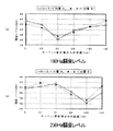
図2(a)は室内の運転者の耳位置(運転者が騒音を聞き取る位置)における騒音レベルを示すグラフであり、図2(b)は室内の後席乗車員の耳位置(後席乗車員が騒音を聞き取る位置)における騒音レベルを示すグラフである。図2(a),(b)から、騒音レベルは、運転者の耳位置と後席乗車員の耳位置の両方とも、周波数が160Hz及び250Hzのときに高くなることがわかる。さらに、図2(a)から、運転者の耳位置における160Hz及び250Hzでの騒音レベルは、流れ抵抗値の小さいカーペット層Aの方が低く、図2(b)から、後席乗員者の耳位置における160Hz及び250Hzでの騒音レベルは、流れ抵抗値の大きいカーペット層Bの方が低いことがわかる。
【0049】
図3(a),(b)は、最も騒音レベルの高い周波数である160Hzと250Hzについて、室内の運転者の足元のカーペット層近接位置(カーペット層の表面から5cmの位置)から、運転者の耳位置(カーペット層の表面から130cmの位置)まで、25cm間隔で騒音レベルを測定した結果を示すグラフである。図3(a)は160Hzの場合について示し、図3(b)は250Hzの場合について示している。
【0050】
また、図4(a),(b)は、最も騒音レベルの高い周波数である160Hzと250Hzについて、室内の後席乗車員の足元のカーペット層近接位置(カーペット層の表面から5cmの位置)から、後席乗車員の耳位置(カーペット層の表面から105cmの位置)まで、25cm間隔で騒音レベルを測定した結果を示すグラフである。図4(a)は160Hzの場合について示し、図4(b)は250Hzの場合について示している。
【0051】
図3(a),(b)および図4(a),(b)から、騒音レベルはカーペット層からの距離によって変化することがわかる。これは、カーペット層の流れ抵抗値により、自動車室内空間の音響モードが位置によって変化するためであると考えられる。
【0052】
ここで、運転者の耳位置(カーペット層の表面から130cmの位置)と、後席乗車員の耳位置(カーペット層の表面から105cmの位置)とに着目すると、運転者の耳位置での騒音レベルはカーペット層Aを用いた場合の方が低く(図3(a),(b))、後席乗車員の耳位置での騒音レベルはカーペット層Bを用いた場合の方が低い(図4(a),(b))ことがわかる。つまり、エンジンに比較的近い位置である運転者の耳位置ではカーペット層11の流れ抵抗値を比較的低く設定し、エンジンに比較的遠い位置である後席乗車員の耳位置ではカーペット層11の流れ抵抗値を比較的高く設定することで、室内の騒音レベルを全体的に低くすることができることがわかる。エンジンに比較的近い位置と遠い位置とでカーペット層11の流れ抵抗値にどの程度の差を設けるかは、室内全体においてバランスのとれた吸音性、遮音性を発揮することができるように、室内の形状等によって個々に設定されることが好ましい。
【0053】
なお、上記では接合材11aを用いてカーペット層11と緩衝材層12とを接着する例を示したが、カーペット層11と緩衝材層12とは必ずしも互いに接着されている必要はなく、例えば、緩衝材層12の上にカーペット層11が単に載せられた構成であってもよい。
【0054】
(ピースマット)
図5は、本発明の一実施形態に係るピースマットを示す断面図である。
【0055】
図5に示すように、本実施形態のピースマット20は、パイル糸が立毛成形されてなる立毛パイル層21と、立毛パイル層21を担持した基布層22と、基布層22の裏面との間に不連続な接合材23を介して積層されたクッション材層24とからなり、立毛パイル層21の表面からクッション材層24の裏面にかけて通気性を有している。このピースマット20は、好ましくは、立毛パイル層21を担持した基布層22とクッション材層24とを、それらの間に不連続に配置した低融点熱可塑性樹脂からなる接合材23を挟んで重ね合わせ、サクションヒーター(不図示)で通気加熱して接合材23を可塑化させた後、プレスローラー(不図示)で基布層22とクッション材層24とを押圧することによって作製される。
【0056】
ピースマット20は、その周縁部を、基布層22とクッション材層24とを共に溶断してトリミングすることが好ましい。溶断によってトリミングされた切断面は、美観が向上する。基布層22やクッション材層24が熱可塑性素材で構成されていれば、例えばレーザー光を照射してピースマット20の周縁部を溶断することができる。
【0057】
ピースマット20の各構成(立毛パイル層21、基布層22、クッション材層24)の素材は、上記のフロア敷設材10のカーペット層11および緩衝材層12の素材と同種のものを用いることが可能である。好適な例としては、立毛パイル層21には、パイル高さが5〜15mmであり、単位面積当たり500〜1300g/m2であるポリプロピレン繊維またはナイロン繊維を用い、基布層22には、基布の裏面に低目付のラテックス加工を施してなる、単位面積当たり80〜150g/m2のポリエステルのスパンボンドを用い、クッション材層24には、繊維太さが4〜30デニールのレギュラー繊維(70〜90wt%)に対して、繊維太さが2〜6デニールの低融点繊維(10〜30wt%)が混繊されている、厚さが2〜5mmで、単位面積当たり100〜700g/m2のポリエステル不織布や、厚さが2〜5mmで、単位面積当たり40〜500g/m2の軟質ウレタンフォームを用いることができる。
【0058】
ピースマット20の立毛パイル層21の表面からクッション材層24の裏面への流れ抵抗値が100Nsm-3以上、1500Nsm-3以下に調整されていれば、フロア敷設材10(図1参照)上にピースマット20を配設した際に吸音性および遮音性が高められ、室内の騒音は低減される。この吸音性および遮音性を調整するために、クッション材層24等に孔加工を施してもよい。
【0059】
立毛パイル層21および基布層22の流れ抵抗値とクッション材層24の流れ抵抗値については、本実施形態では、立毛パイル層21の表面から基布層22の裏面への流れ抵抗値が80Nsm-3以上、700Nsm-3以下に調整され、クッション材層24の表面から裏面への流れ抵抗値が40Nsm-3以上、1000Nsm-3以下に調整されている。
【0060】
(フロア敷設材とピースマットとの配設構造)
図6は、図1に示したフロア敷設材上に図5に示したピースマットを配設した状態を示す断面図である。
【0061】
フロア敷設材10の上にピースマット20を配設してなる配設構造に、最適な吸音性および遮音性を発揮させるためには、実車走行試験を行い、フロア敷設材10上の各位置にピースマット20を置いて室内の騒音レベルを測定して、その実車ごとにピースマット20の最適な配設位置を見出すのが最も良い手法である。
【0062】
しかし、これまで多くの異なる自動車について騒音レベルの測定を行い、さらにソフトウェアを利用して解析した結果から、室内の騒音レベルを低下させるためには、フロア敷設材10上のピースマット20の最適な配設について、一般的に以下の▲1▼〜▲3▼の基準を満たしている必要があることが判明している。
【0063】
▲1▼フロア敷設材10とピースマット20とが重ね合わされている領域の、フロア敷設材10のうちのカーペット層11とピースマット20とを合わせた部分は、単位面積当たり1500g/m2以上、4500g/m2以下に調整されているとともに、ピースマット20の表面からカーペット層11の裏面への流れの抵抗値が150Nsm-3以上、1800Nsm-3以下に調整されていること。
【0064】
▲2▼少なくとも乗員の足下(乗用車の場合は、少なくとも前席乗員の足下)の部分が平坦になるように配設すること。
【0065】
▲3▼ピースマット20の分割されている部分や、ピースマット20とフロア敷設材10との間に隙間が生じていないこと。
【0066】
そのため、実車試験によらなくても、上記の基準に沿うように配設構造を構成することによって、配設構造の最適な吸音性および遮音性を得ることができる。図6に示したフロア敷設材とピースマットとの配設構造では、室内に存在する音波のうち、ピースマット20方向に進んだ成分N1は、ピースマット20を抜けてフロア敷設材10に達し、フロア敷設材10によって高い比率で吸音される。そのため、フロア敷設材10に達した成分N1のうちフロア敷設材10で反射される成分N2は非常に少なくなり、室内の騒音が低減される。
【0067】
ピースマット20は、フロア敷設材10の敷設位置の形状に追随して変形する柔軟性を有し、フロア敷設材10上に配設する際にフロア敷設材10との間に大きな隙間を生じないことが好ましい。
【0068】
フロア敷設材10のカーペット層11(図1参照)の表面のうち、ピースマット20が配設される部分は、他の部分よりも低く設けられている。そのため、ユーザーが、フロア敷設材10の上にピースマット20の配設位置の形状に合わない市販のピースマットを配設しようとしても、完全に配設することができないので、純正でないピースマットが配設されることを防止できる。また、ユーザーがピースマット20の配設位置を認識し易くなるので、ピースマットが、設置しても吸音性が最適化されない、誤った位置に配設されるおそれがなくなる。さらには、配設後のピースマット20の位置ずれが起こりにくくなる。
【0069】
なお、フロア敷設材10のカーペット層11の表面のうち、ピースマット20が配設される部分を他の部分よりも低く設ける手法としては、カーペット層11を成形する際にこの部分を他の部分よりも低くするように成形する手法を用いてもよいし、あるいは、図6に示すように、カーペット層11の表面の、ピースマット20が配設される部分のパイルの高さを、他の部分のパイルよりも低く設ける手法を用いてもよい。
【0070】
また、フロア敷設材10およびピースマット20の少なくとも一方には、水を弾く撥水性の素材からなる撥水層と、水を吸収する素材からなる吸水層とのうちの少なくともいずれか1つが設けられていることが好ましい。これにより、例えば乗員の足下に付着して室内に持ち込まれる水分等がピースマット20やフロア敷設材10の中にしみ込むのを抑えることができ、ピースマット20やフロア敷設材10の有する吸音性および遮音性が、そのような水分等によって低下してしまうことを防止することが可能になる。
【0071】
さらに、フロア敷設材10の緩衝材層12(図1参照)およびピースマット20のクッション材層24(図5参照)は、空気を含有する多数の孔が少なくとも一部に設けられていてもよい。これにより、配設構造全体のクッション性が向上し、また、吸音性、遮音性を調整することができる。
【0072】
【実施例】
以下、上記に説明したフロア敷設材、ピースマット、およびこれらの配設構造の実施例について説明する。
【0073】
(各実施例および各比較例の構成)
<実施例1>
通気性を持つ以下のフロア敷設材10の上に、以下のピースマット20を配設した。
【0074】
本実施例のフロア敷設材10には、流れ抵抗値が400Nsm-3のニードルパンチカーペットからなるカーペット層11に、厚さが30mmで、密度ρが0.1g/cm3のポリエステル繊維フェルトからなる緩衝材層12を積層させて作製したものを用いた。
【0075】
また、本実施例のピースマット20には、単位面積当たり600g/m2の立毛パイル層21を担持した、単位面積当たり120g/m2の基布の裏面にSBR(スチレン・ブタジエン・ゴム)樹脂のラテックス加工を施してなる基布層22に、接合材23としてポリエチレン樹脂の短繊維を単位面積当たり100g/m2に散布して形成した貼着層を介して、単位面積当たり100g/m2のポリエステル繊維不織布からなるクッション材層24を積層して作製した、流れ抵抗値が100Nsm-3のものを用いた。
【0076】
<実施例2>
実施例1と同じフロア敷設材10の上に、以下のピースマット20を配設した。
【0077】
本実施例のピースマット20には、単位面積当たり600g/m2の立毛パイル層21を担持した、単位面積当たり120g/m2の基布の裏面にSBR樹脂のラテックス加工を施してなる基布層22に、接合材23としてポリエチレン樹脂の短繊維を単位面積当たり150g/m2に散布して形成した貼着層を介して、単位面積当たり250g/m2のポリエステル繊維不織布からなるクッション材層24を積層して作製した、流れ抵抗値が500Nsm-3のものを用いた。
【0078】
<実施例3>
実施例1と同じフロア敷設材10の上に、以下のピースマット20を配設した。
【0079】
本実施例のピースマット20には、単位面積当たり600g/m2の立毛パイル層21を担持した、単位面積当たり120g/m2の基布の裏面にSBR樹脂のラテックス加工を施してなる基布層22に、接合材23としてポリエチレン樹脂の短繊維を単位面積当たり350g/m2に散布して形成した貼着層を介して、単位面積当たり550g/m2のポリエステル繊維不織布からなるクッション材層24を積層して作製した、流れ抵抗値が1000Nsm-3のものを用いた。
【0080】
<実施例4>
実施例1と同じフロア敷設材10の上に、以下のピースマット20を配設した。
【0081】
本実施例のピースマット20には、単位面積当たり600g/m2の立毛パイル層21を担持した、単位面積当たり120g/m2の基布の裏面にSBR樹脂のラテックス加工を施してなる基布層22に、接合材23としてポリエチレン樹脂の短繊維を単位面積当たり500g/m2に散布して形成した貼着層を介して、単位面積当たり700g/m2のポリエステル繊維不織布からなるクッション材層24を積層して作製した、流れ抵抗値が1500Nsm-3のものを用いた。
【0082】
[比較例1]
実施例1と同じフロア敷設材10のみを用い、フロア敷設材10上にピースマットは配設していない。つまり、本比較例では、ピースマットの流れ抵抗値はゼロである。
【0083】
[比較例2]
実施例1と同じフロア敷設材10の上に、以下のピースマットを配設した。
【0084】
本比較例のピースマットには、単位面積当たり600g/m2の立毛パイル層を担持した、単位面積当たり120g/m2の基布の裏面に、単位面積当たり1300g/m2のゴム質の裏打材を施した、通気の無い構成のものを用いた。つまり、本比較例では、ピースマットの流れ抵抗値は無限大である。
【0085】
[比較例3]
実施例1と同じフロア敷設材10の上に、以下のピースマット20を配設した。
【0086】
本比較例のピースマット20には、単位面積当たり600g/m2の立毛パイル層21を担持した、単位面積当たり120g/m2の基布の裏面にSBR樹脂のラテックス加工を施してなる基布層22に、接合材23としてポリエチレン樹脂の短繊維を単位面積当たり550g/m2に散布して形成した貼着層を介して、単位面積当たり800g/m2のポリエステル繊維不織布からなるクッション材層24を積層して作製した、流れ抵抗値が2000Nsm-3のものを用いた。
【0087】
(評価方法)
(1)実験室での垂直入射吸音率および透過損失(遮音)の評価
各実施例および各比較例のフロア敷設材とピースマットとの配設構造に相当するサンプルを作製し、これらのサンプルの各々についてピースマットのパイル方向からノイズを入射させたときの400〜4000Hzにおける吸音率を測定し、互いの測定結果を比較した。また、上記の各サンプルに、実車両と同様に厚さ0.8mmの鉄板からなるパネルをそれぞれ組み合わせたものの各々について、パネル側からノイズを入射させたときの400〜4000Hzにおける透過損失を測定し、互いの測定結果を比較した。
(2)実車による自動車室内の騒音レベルの評価
排気量が2500ccのエンジンをフロント側に備えた、リヤ駆動方式のセダン型自動車である実験車両に、各実施例および各比較例のフロア敷設材とピースマットとの配設構造に相当するサンプルを設置し、その実験車両を粗面路に相当するダイナモ上で時速60kmの速度で定速走行させて、自動車室内の運転者の耳位置においたマイクロホンで125〜4000Hzにおける騒音レベルを測定した。
【0088】
なお、ピースマットは運転席、助手席、および後席の足元部と後席のトンネル上部とに設置した。また、ピースマットの表面の面積は合計で約1.5m2とした。この場合、ピースマットの表面の面積は、フロア敷設材の表面の面積の約30%を占める。
【0089】
(評価結果)
図7は実験室での400〜4000Hzにおける垂直入射吸音率の測定結果を示すグラフ、図8は実験室での400〜4000Hzにおける透過損失の測定結果を示すグラフ、図9は実車による自動車室内の運転者の耳位置での騒音レベルの測定結果を示すグラフである。
【0090】
比較例1を除くと、ピースマットの流れ抵抗値は、実施例1が最も小さく、次に、実施例2,3,4の順に小さく、次に比較例3,2の順に小さい。このことから、垂直入射吸音率は、図7より、ほぼ全ての周波数帯域において、ピースマットの流れ抵抗値が小さい順に高くなっていることがわかる。一方、透過損失はこれとは逆に、図8より、ほぼ全ての周波数帯域において、ピースマットの流れ抵抗値が高い順に高くなっていることがわかる。また、図9より、自動車室内の運転者の耳位置での騒音レベルも、ほぼ全ての周波数帯域において、ピースマットの流れ抵抗値が高い順に高くなっていることがわかる。
【0091】
ここで、比較例1はピースマットの流れ抵抗値が実質的にゼロであり、実施例1の流れ抵抗値よりも小さいにもかかわらず、図7に示すように、比較例1の垂直入射吸音率が実施例1よりも低くなっている。これは、ピースマット自体も入射音をいくらか吸収するが、比較例1はピースマットを備えていないため、ピースマット自体が有する吸音性が得られていないことに依るものと考えられる。
【0092】
なお、上記では、フロア敷設材10やピースマット20を乗用自動車の室内に配設する例を用いて説明したが、これらのフロア敷設材10やピースマット20をバスやトラックの室内、あるいは、船、電車車両、飛行機等のあらゆる乗物の室内に配設した場合であっても、上記に説明した吸音効果および遮音効果を同様に得ることができる。
【0093】
【発明の効果】
以上説明したように、本発明のフロア敷設材は、カーペット層が、表面から裏面への流れ抵抗値が100Nsm-3以上、1000Nsm-3以下に調整されており、緩衝材層が、空気を包含する性質の素材からなり、表面から裏面への流れ抵抗値が40Nsm-3以上、800Nsm-3以下に調整されており、乗物が備えている原動機に比較的近い位置に配置されるフロア敷設材のカーペット層の流れ抵抗値が、原動機に比較的遠い位置に配置されるフロア敷設材のカーペット層の流れ抵抗値よりも低く設定されているので、室内の騒音レベルを低減することができる。
【図面の簡単な説明】
【図1】本発明の一実施形態に係るフロア敷設材を示す断面図である。
【図2】室内の運転者および後席乗車員の耳位置における騒音レベルを示すグラフである。
【図3】最も騒音レベルの高い周波数である160Hzと250Hzについて、室内の運転者の足元のカーペット層近接位置から運転者の耳位置まで、25cm間隔で騒音レベルを測定した結果を示すグラフである。
【図4】最も騒音レベルの高い周波数である160Hzと250Hzについて、室内の後席乗車員の足元のカーペット層近接位置から後席乗車員の耳位置まで、25cm間隔で騒音レベルを測定した結果を示すグラフである。
【図5】本発明の一実施形態に係るピースマットを示す断面図である。
【図6】図1に示したフロア敷設材上に図5に示したピースマットを配設した状態を示す断面図である。
【図7】実験室での400〜4000Hzにおける垂直入射吸音率の測定結果を示すグラフである。
【図8】実験室での400〜4000Hzにおける透過損失の測定結果を示すグラフである。
【図9】実車による自動車室内の運転者の耳位置での騒音レベルの測定結果を示すグラフである。
【符号の説明】
10 フロア敷設材
11 カーペット層
11a,23 接合材
12 緩衝材層
20 ピースマット
21 立毛パイル層
22 基布層
24 クッション材層[0001]
[Industrial application fields]
The present invention relates to a floor laying material which is laid on the interior side of the floor panel of the vehicle in order to reduce noise in the room of the vehicle.
[0002]
[Prior art]
In order to reduce the noise in passenger compartments, luggage compartments, engine compartments, and other automobile compartments, the use of laying materials (specifically, carpets, dash silencers, and other trim materials as interior materials) It has been conventionally known that control of the flow resistance value (air permeability) is an important factor.
[0003]
Conventional techniques relating to such control of the flow resistance value are disclosed in Japanese Patent Application Laid-Open Nos. 51-112889, 56-144204, and 59-186750. All of these prior arts attempt to increase the sound absorption of the silencer by setting the air permeability of the silencer within a predetermined range.
[0004]
Regarding this type of conventional technology, Japanese Patent Publication No. 2000-516175 (PCT / CH97 / 00412) discloses the most detailed investigation of the flow resistance value of the laying material.
[0005]
This Japanese translation of PCT publication No. 2000-516175 discloses “a multi-function sound insulation kit including at least one planar body part and a noise reduction assembly package composed of a plurality of layers”. comprising a "hard layer having a fine porous", the hard layer may have a total resistance against the airflow of R t = 500Nsm -3 ~R t = 2500Nsm -3, especially R t = 900Nsm -3 It is to have a total resistance against the air flow that ~R t = 2000Nsm -3. The flow resistance value of this hard layer is considerably lower than the flow resistance value disclosed heretofore. The prior art disclosed in this domestic publication attempts to achieve high sound absorption in an intermediate frequency range to a high frequency range by defining the flow resistance value of the hard layer in this way.
[0006]
By the way, the prior art disclosed in Japanese Translation of PCT International Publication No. 2000-516175, which attempts to control the flow resistance value of the assembly to quiet the interior of the automobile, is such that the user who purchased the automobile disturbs the balance of the flow resistance value of the assembly. It is not intended to make any significant changes. For example, if the assembly is a floor laying material that has a significant effect on sound absorption in the passenger compartment, the flow resistance value balance will change if the user lays an optional piece mat for preventing soiling on the floor laying material under the feet. As a result, the sound absorbing property intended by the original design cannot be exhibited. In particular, in a floor laying material that is designed to absorb sound with a focus on the flow resistance value, when this balance is lost, there is a risk that the noise level in the automobile interior will be higher than in the original design.
[0007]
Therefore, a piece mat or the like should not be placed on this prior art assembly (floor laying material). In general, car manufacturers sell cars without the option of a piece mat, but many users who do not have expertise in acoustic design purchase their own piece mats on the assembly (floor laying material). Sometimes put. If it does so, the flow resistance value of an assembly (floor laying material) will change, and the quietness in the automobile interior at the beginning of design cannot be obtained.
[0008]
[Problems to be solved by the invention]
However, enlightenment with instruction manuals and the like has the following problems even if the user succeeds in discouraging placing the piece mat on the assembly (floor laying material).
[0009]
It is unavoidable that some moisture or the like adheres to the passenger's feet and is brought into the passenger compartment (particularly the floor surface of the passenger's feet). If a piece mat is not used, the moisture that has been brought into the room will sink into the floor laying material over a long period of time, contaminating the floor laying material, and initializing the flow resistance value of the floor laying material. There is a possibility of increasing the value. As a result, the flow resistance value also changes, and the quietness in the automobile interior at the beginning of the design cannot be obtained.
[0010]
Regarding the sound absorption in the automobile interior, the sound absorption effect when a single piece mat is disposed is disclosed in Japanese Patent Application Laid-Open No. 2001-47926, which is a prior application. However, there has been no example of research on the effect of combining a floor laying material and a piece mat.
[0011]
Many conventional piece mats are made of a molded resin mat or rubber mat because they are intended for antifouling and waterproofing. For this reason, many conventional piece mats have no air permeability and their flow resistance value is infinite. Such a piece mat has a property of reflecting sound waves rather than a property of absorbing sound waves in the interior of an automobile. Therefore, by disposing the piece mat in the interior of the automobile, the sound absorption in the automobile interior is lowered and the noise level is increased. The present inventors confirmed this fact by an actual vehicle test.
[0012]
This invention is made | formed in view of the subject which said prior art has, The objective is to provide the floor-laying material with which sound absorption property and sound insulation property were optimized.
[0013]
[Means for Solving the Problems]
In order to achieve the above object, the floor laying material of the present invention comprises a carpet layer and a buffer material layer laminated on the back surface of the carpet layer, and is laid on a floor panel provided on the vehicle interior side. In the floor laying material, the carpet layer has a flow resistance value from the front surface to the back surface adjusted to 100 Nsm −3 or more and 1000 Nsm −3 or less, and the cushioning layer is made of a material including air. The flow resistance value from the front surface to the back surface is adjusted to 40 Nsm −3 or more and 800 Nsm −3 or less, and the carpet layer of the floor laying material arranged at a position relatively close to the prime mover included in the vehicle The flow resistance value is set lower than the flow resistance value of the carpet layer of the floor laying material arranged at a position relatively far from the prime mover .
[0014]
In particular, the floor laying material of the present invention has improved sound absorption by adjusting the flow resistance value from the front surface to the back surface of the carpet layer to 100 Nsm −3 or more and 1000 Nsm −3 or less.
[0015]
The following formula (1),
Sound absorption coefficient = 4Rn / {(Rn + 1) 2 + Xn 2 } Expression (1)
(Here, the value of the acoustic resistance Rn is between 1 and 2, and the acoustic reactance Xn indicates a higher sound absorption rate as it approaches 0.)
When the flow resistance value is in the range of 100 Nsm −3 or more and 500 Nsm −3 or less, the sound resistance Rn and the sound reactance Xn, which are parameters of the sound absorption rate, increase the sound absorption rate. When the flow resistance value exceeds 500 Nsm −3 , the value of Rn begins to gradually deviate from the range in which the sound absorption rate is increased. When the flow resistance value exceeds 1000 Nsm −3 , both the values of Rn and Xn exhibit the sound absorption rate. It is out of the range to be raised. Note that the sound absorption rate is also increased when the flow resistance value is less than 100 Nsm −3 , but in this case, the strength of carrying the pile or the like which is the design of the carpet layer is reduced, and the pile is likely to fall off. This is not practically preferable. From this, by adjusting the flow resistance value from the front surface to the back surface of the carpet layer to 100 Nsm −3 or more and 1000 Nsm −3 or less, it is possible to obtain a certain effect in terms of practically improving sound absorption. Recognize.
[0016]
Furthermore, from the above viewpoint, it is preferable that the flow resistance value of the carpet layer is adjusted to 100 Nsm −3 or more and 500 Nsm −3 or less.
[0017]
Further, a bonding material made of a thermoplastic resin is discontinuously disposed on the back surface of the carpet layer, and the carpet layer and the cushioning material layer may be laminated via the bonding material. . As described above, when a bonding material made of a thermoplastic resin disposed discontinuously on the back surface of the carpet layer is disposed, the bonding material is heated to form a sticking material. The buffer material layer can be bonded to the back surface of the carpet layer without greatly changing the flow resistance value.
[0018]
In the carpet layer, a molding material made of a thermoplastic resin formed in a powder form or a fiber form may be disposed in a dispersed state.
[0019]
As in the present invention, the flow resistance value of the carpet layer is easily adjusted by disposing the molding material made of the thermoplastic resin formed in the form of powder or fiber in the carpet layer in a dispersed state. It becomes possible. As a method of dispersing such a molding material in the carpet layer, the molding material is mixed uniformly in the carpet layer, or the carpet layer is formed into a multilayer structure, and the molding material is interposed between the layers. For example, it is suitable to spread the powder evenly. The molding material dispersed in the carpet layer is plasticized by heat applied at the time of forming the carpet layer to impart formability (shape maintenance) to the carpet layer, and at the same time, the pressing applied at the time of forming the carpet layer. The pressure substantially loses some of its powdery or fibrous form while substantially entering the stitches of the fibrous carpet layer and “sealing” some stitches of the carpet layer. Of the carpet layers formed in this way, the stitches that are “sealed” by the molding material have no air permeability, and the stitches that are not “sealed” have air permeability. Therefore, the flow resistance value of the carpet layer can be easily adjusted by changing the proportion of the stitches of the carpet layer where “sealing” is performed.
[0020]
For example, the flow resistance value of the carpet layer can be easily adjusted by setting the size or density of the powdered or fibrous molding material according to the molding conditions such as temperature and pressing force during molding of the carpet layer. can do. It is also possible to partially change the flow resistance value of the carpet layer by partially changing the arrangement density of the molding material. On the other hand, when a conventional continuous sheet-like backing material is used as a material for imparting moldability to the carpet layer, the flow resistance value of the carpet layer should be finely adjusted or partially adjusted. It is difficult.
[0022]
Moreover, the said buffer material layer may be provided so that the thickness in the state laid on the said floor panel may be 5 mm or more. Furthermore, the thickness of the buffer material layer may be 20 mm or more. The cushioning material layer is made of a material that includes air, and provides an air layer between the carpet layer and the floor panel, and contributes to reducing the indoor noise level. If the buffer material layer has a flow resistance value adjusted to 40 Nsm −3 or more and 800 Nsm −3 or less as described above, the thickness thereof should be 5 mm or more, preferably 20 mm or more. However, it is effective in reducing the indoor noise level.
[0034]
DETAILED DESCRIPTION OF THE INVENTION
Next, embodiments of the present invention will be described with reference to the drawings.
[0035]
(Floor laying material)
FIG. 1 is a cross-sectional view showing a floor laying material according to an embodiment of the present invention.
[0036]
A
[0037]
The carpet layer 11 preferably includes a molding material (not shown) made of melt fiber or powder having a relatively low melting temperature. In this case, it is preferable that these melt fibers and powders are disposed in the carpet layer 11 in a substantially uniform manner. As a method of disperse the melt fiber or powder in the carpet layer 11, a method of uniformly mixing the melt fiber or powder into the carpet layer 11 may be used, or the carpet layer 11 may be a multilayer. A method may be used in which the molding material is uniformly dispersed between the layers.
[0038]
The
[0039]
Furthermore, the melt fiber and powder contained in the carpet layer 11 contribute to the entanglement of the fibers constituting the carpet layer 11, and also adjust the flow resistance value of the carpet layer 11 within a target range. Can be used.
[0040]
On the other hand, the bonding material 11a is formed, for example, by spraying a low-melting point thermoplastic resin having a relatively low melting point temperature on the back surface of the carpet layer 11 in the form of powder or fiber. In this case, the surface density of the dispersion is preferably 30 to 200 g / m 2 . According to this, after the joining material 11a made of the low melting point thermoplastic resin is sprayed on the back surface of the carpet layer 11, the joining material 11a is directly heated, or the carpet layer 11 is heated and indirectly heated. As a result, the bonding material 11a is plasticized. Then, the buffer material layer 12 is bonded to the back surface of the carpet layer 11 when the bonding material 11a is plasticized. Then, the plasticized bonding material 11a is entangled with the carpet layer 11 and the buffer material layer 12, and adheres both when solidifying. At this time, since the carpet layer 11 and the buffer material layer 12 are bonded to each other in a discontinuous manner by the dispersed bonding material 11a, the air permeability of the carpet layer 11 is not impaired.
[0041]
The carpet layer 11 has an aeration blocking property and the like, and the flow resistance value from the front surface to the back surface is 100 Nsm −3 or more and 1000 Nsm −3 or less, preferably 100 Nsm −3 or more and 500 Nsm −3 or less. It has been adjusted. As a means for adjusting the flow resistance value of the carpet layer 11, any means can be used, and for example, partial punching of the carpet layer 11 is included.
[0042]
The cushioning material layer 12 is made of a material that includes air and has a “waist” that has repulsion resistance to withstand pressing. As a material of the buffer material layer 12, there is, for example, a mixed fiber mat of polyester fibers (95 to 50 wt%) and low melting point thermoplastic fibers (5 to 50 wt%) described in Utility Model Registration No. 25557108. In addition, a resin foam such as urethane foam can be used as the material of the buffer layer 12.
[0043]
The thickness of the buffer material layer 12 is 5 mm or more, preferably 20 mm or more in the laid state. Although the buffer material layer 12 may be molded, a thickness of 5 mm or more is ensured in substantially all the portions. Further, the buffer material layer 12 is adjusted to have a flow resistance value of 40 Nsm −3 or more and 800 Nsm −3 or less. The cushioning material layer 12 is made of a material that includes air as described above, and provides an air layer between the carpet layer 11 and a floor panel (not shown), thereby contributing to a reduction in indoor noise level. Is. When the buffer material layer 12 has a flow resistance value adjusted to 40 Nsm −3 or more and 800 Nsm −3 or less as described above, the thickness is set to 5 mm or more, preferably 20 mm or more. This is effective in reducing the noise level in the room.
[0044]
In addition, even if it is a raw material with a poor property containing air, it can be used as a raw material of the buffer material layer 12 by performing many holes processing and providing air inclusion property. For example, in a standing wall portion such as a tunnel portion where rigidity is required for the laying material (carpet layer), it is necessary to provide a hard sheet or the like that does not easily contain air as the buffer material layer 12, but even in this case, the hard sheet or the like is drilled. By performing the above, air inclusion can be imparted to the hard sheet or the like.
[0045]
Further, the flow resistance value of the carpet layer 11 of the
[0046]
Below, the experimental result which shows the reason why indoor noise reduces by the said structure is demonstrated.
[0047]
The inventors of the present invention installed a floor laying material having a carpet layer A having a flow resistance value of 400 Nsm −3 in the room of an experimental vehicle that is a sedan type automobile equipped with an engine with a displacement of 3000 cc on the front side. In the case where a floor laying material having a carpet layer B having a flow resistance value of 2000 Nsm -3 is installed, the experimental vehicle is driven at a constant speed of 60 km / h on a dynamo corresponding to a rough road, Noise levels were measured with microphones installed at various sites.
[0048]
FIG. 2A is a graph showing the noise level at the driver's ear position (the position at which the driver hears noise) in the room, and FIG. 2B is the ear position (rear seat ride) of the rear seat passenger in the room. It is a graph which shows the noise level in the position where a worker hears noise. 2 (a) and 2 (b), it can be seen that the noise level increases when the frequency is 160 Hz and 250 Hz in both the driver's ear position and the rear seat passenger's ear position. Further, from FIG. 2A, the noise level at 160 Hz and 250 Hz at the driver's ear position is lower in the carpet layer A having a smaller flow resistance value, and from FIG. It can be seen that the noise level at 160 Hz and 250 Hz in the position is lower in the carpet layer B having a larger flow resistance value.
[0049]
3 (a) and 3 (b) show the frequency of the highest noise level of 160Hz and 250Hz from the carpet layer proximity position (5 cm from the surface of the carpet layer) at the driver's feet in the room. It is a graph which shows the result of having measured the noise level in 25 cm intervals to the ear position (position 130 cm from the surface of the carpet layer). FIG. 3A shows the case of 160 Hz, and FIG. 3B shows the case of 250 Hz.
[0050]
4 (a) and 4 (b) show the highest noise level frequencies of 160Hz and 250Hz from the carpet layer proximity position (5 cm from the surface of the carpet layer) at the foot of the passenger in the rear seat in the room. It is a graph which shows the result of having measured the noise level at intervals of 25 cm to the rear seat passenger's ear position (position of 105 cm from the surface of the carpet layer). 4A shows the case of 160 Hz, and FIG. 4B shows the case of 250 Hz.
[0051]
3A and 3B and FIGS. 4A and 4B that the noise level changes depending on the distance from the carpet layer. This is considered to be because the acoustic mode of the automobile interior space changes depending on the position due to the flow resistance value of the carpet layer.
[0052]
Here, focusing on the driver's ear position (position 130 cm from the surface of the carpet layer) and the rear seat passenger's ear position (position 105 cm from the surface of the carpet layer), the noise at the driver's ear position. The level is lower when the carpet layer A is used (FIGS. 3A and 3B), and the noise level at the ear position of the rear seat occupant is lower when the carpet layer B is used (FIG. 3). 4 (a), (b)). That is, the flow resistance value of the carpet layer 11 is set to be relatively low at the driver's ear position that is relatively close to the engine, and the carpet layer 11 is set to be at the ear position of the rear seat occupant that is relatively far from the engine. It can be seen that the indoor noise level can be lowered overall by setting the flow resistance value relatively high. The difference in the flow resistance value of the carpet layer 11 between a position relatively close to the engine and a position far from the engine is determined so that a balanced sound absorbing property and sound insulating property can be exhibited throughout the room. It is preferable to set them individually according to the shape and the like.
[0053]
In addition, although the example which adhere | attaches the carpet layer 11 and the buffer material layer 12 using the joining material 11a was shown above, the carpet layer 11 and the buffer material layer 12 do not necessarily need to be mutually adhere | attached, for example, The carpet layer 11 may simply be placed on the cushioning material layer 12.
[0054]
(Peace mat)
FIG. 5 is a cross-sectional view showing a piece mat according to an embodiment of the present invention.
[0055]
As shown in FIG. 5, the
[0056]
The
[0057]
The material of each component of the piece mat 20 (the napped pile layer 21, the base fabric layer 22, and the cushion material layer 24) should be the same type as the material of the carpet layer 11 and the cushioning material layer 12 of the
[0058]
If the flow resistance value from the surface of the raised pile layer 21 of the
[0059]
Regarding the flow resistance value of the napped pile layer 21 and the base fabric layer 22 and the flow resistance value of the cushion material layer 24, in this embodiment, the flow resistance value from the surface of the napped pile layer 21 to the back surface of the base fabric layer 22 is 80 Nsm. -3 or more and 700 Nsm -3 or less, and the flow resistance value from the front surface to the back surface of the cushion material layer 24 is adjusted to 40 Nsm -3 or more and 1000 Nsm -3 or less.
[0060]
(Arrangement structure of floor laying material and piece mat)
6 is a cross-sectional view showing a state in which the piece mat shown in FIG. 5 is disposed on the floor laying material shown in FIG.
[0061]
In order to make the arrangement structure in which the
[0062]
However, from the results of measuring the noise level of many different automobiles and analyzing them using software, it is necessary to optimize the
[0063]
(1) In the region where the
[0064]
(2) Arrange at least the feet of passengers (or at least the feet of front passengers in the case of passenger cars) to be flat.
[0065]
(3) There are no gaps between the
[0066]
Therefore, even if it does not depend on a real vehicle test, the optimal sound absorption property and sound insulation of an arrangement | positioning structure can be obtained by comprising an arrangement | positioning structure along said reference | standard. In the arrangement structure of the floor laying material and the piece mat shown in FIG. 6, the component N 1 that has advanced in the direction of the
[0067]
The
[0068]
Of the surface of the carpet layer 11 (see FIG. 1) of the
[0069]
In addition, as a method of providing a portion where the
[0070]
Further, at least one of the
[0071]
Furthermore, the cushioning material layer 12 (see FIG. 1) of the
[0072]
【Example】
Hereinafter, examples of the floor laying material, the piece mat, and the arrangement structure thereof described above will be described.
[0073]
(Configuration of each example and each comparative example)
<Example 1>
The following
[0074]
The
[0075]
In addition, the
[0076]
<Example 2>
On the same
[0077]
In the
[0078]
<Example 3>
On the same
[0079]
In the
[0080]
<Example 4>
On the same
[0081]
In the
[0082]
[Comparative Example 1]
Only the same
[0083]
[Comparative Example 2]
On the same
[0084]
The piece mat of this comparative example has a rubber backing of 1300 g / m 2 per unit area on the back of a base fabric of 120 g / m 2 per unit area carrying a raised pile layer of 600 g / m 2 per unit area. A material-free material with no ventilation was used. That is, in this comparative example, the flow resistance value of the piece mat is infinite.
[0085]
[Comparative Example 3]
On the same
[0086]
In the
[0087]
(Evaluation methods)
(1) Evaluation of normal incidence sound absorption coefficient and transmission loss (sound insulation) in the laboratory Samples corresponding to the arrangement structure of the floor laying material and piece mat in each example and each comparative example were prepared. About each, the noise absorption factor in 400-4000 Hz when noise was injected from the pile direction of a piece mat was measured, and the mutual measurement result was compared. Moreover, the transmission loss at 400 to 4000 Hz was measured for each of the above samples combined with a panel made of an iron plate having a thickness of 0.8 mm as in the actual vehicle when noise was incident from the panel side. The measurement results of each other were compared.
(2) Evaluation of the noise level in the vehicle interior by an actual vehicle An experimental vehicle, which is a rear-drive sedan type vehicle, equipped with an engine with a displacement of 2500 cc on the front side, and floor laying materials of each example and each comparative example, A sample corresponding to an arrangement structure with a piece mat is installed, and the experimental vehicle is driven at a constant speed of 60 km / h on a dynamo corresponding to a rough road, and the microphone is placed at the ear position of the driver in the automobile compartment. The noise level at 125 to 4000 Hz was measured.
[0088]
The peace mats were installed in the driver's, passenger's, and rear seats and on the rear tunnel. The total area of the surface of the piece mat was about 1.5 m 2 . In this case, the surface area of the piece mat occupies about 30% of the surface area of the floor laying material.
[0089]
(Evaluation results)
FIG. 7 is a graph showing the measurement results of the normal incident sound absorption coefficient at 400 to 4000 Hz in the laboratory, FIG. 8 is a graph showing the measurement results of the transmission loss at 400 to 4000 Hz in the laboratory, and FIG. It is a graph which shows the measurement result of the noise level in a driver | operator's ear position.
[0090]
Except for the comparative example 1, the flow resistance value of the piece mat is the smallest in the example 1, the smallest in the order of the examples 2, 3 and 4, and the smallest in the order of the comparative examples 3 and 2. From this, it can be seen from FIG. 7 that the normal incident sound absorption coefficient increases in ascending order of the flow resistance value of the piece mat in almost all frequency bands. On the other hand, it can be seen from FIG. 8 that the transmission loss increases in descending order of the flow resistance value of the piece mat in almost all frequency bands. Further, it can be seen from FIG. 9 that the noise level at the driver's ear position in the automobile compartment also increases in the order of increasing flow resistance value of the piece mat in almost all frequency bands.
[0091]
Here, in Comparative Example 1, although the flow resistance value of the piece mat is substantially zero and smaller than the flow resistance value of Example 1, as shown in FIG. The rate is lower than in Example 1. This is considered to be due to the fact that the piece mat itself absorbs some of the incident sound, but since the comparative example 1 does not include the piece mat, the sound absorbing property of the piece mat itself is not obtained.
[0092]
In the above description, the
[0093]
【The invention's effect】
As described above, in the floor laying material of the present invention, the carpet layer has the flow resistance value from the front surface to the back surface adjusted to 100 Nsm −3 or more and 1000 Nsm −3 or less, and the cushioning material layer includes air. Of the floor laying material that is arranged at a position relatively close to the prime mover of the vehicle , the flow resistance value from the front surface to the back surface is adjusted to 40 Nsm -3 or more and 800 Nsm -3 or less . Since the flow resistance value of the carpet layer is set lower than the flow resistance value of the carpet layer of the floor laying material arranged at a position relatively far from the prime mover, the noise level in the room can be reduced.
[Brief description of the drawings]
FIG. 1 is a cross-sectional view showing a floor laying material according to an embodiment of the present invention.
FIG. 2 is a graph showing a noise level at an ear position of an indoor driver and a rear seat passenger.
FIG. 3 is a graph showing the results of measuring noise levels at intervals of 25 cm from the position close to the carpet layer in the driver's feet to the driver's ear position for the highest noise level frequencies of 160 Hz and 250 Hz. .
FIG. 4 shows the results of measuring the noise level at intervals of 25 cm from the position near the carpet layer at the foot of the rear seat occupant to the ear position of the rear seat occupant for the highest noise level of 160 Hz and 250 Hz. It is a graph to show.
FIG. 5 is a cross-sectional view showing a piece mat according to an embodiment of the present invention.
6 is a cross-sectional view showing a state in which the piece mat shown in FIG. 5 is disposed on the floor laying material shown in FIG. 1;
FIG. 7 is a graph showing measurement results of normal incidence sound absorption coefficient at 400 to 4000 Hz in a laboratory.
FIG. 8 is a graph showing measurement results of transmission loss at 400 to 4000 Hz in a laboratory.
FIG. 9 is a graph showing the measurement result of the noise level at the ear position of the driver in the vehicle interior using an actual vehicle.
[Explanation of symbols]
DESCRIPTION OF
Claims (6)
前記カーペット層は、表面から裏面への流れ抵抗値が100Nsm-3以上、1000Nsm-3以下に調整されており、
前記緩衝材層は、空気を包含する性質の素材からなり、表面から裏面への流れ抵抗値が40Nsm-3以上、800Nsm-3以下に調整されており、
前記乗物が備えている原動機に比較的近い位置に配置される前記フロア敷設材の前記カーペット層の前記流れ抵抗値は、前記原動機に比較的遠い位置に配置される前記フロア敷設材の前記カーペット層の前記流れ抵抗値よりも低く設定されていることを特徴とするフロア敷設材。A floor laying material comprising a carpet layer and a cushioning material layer laminated on the back surface of the carpet layer, and laid on a floor panel provided on the indoor side of the vehicle,
The carpet layer has a flow resistance value from the front surface to the back surface adjusted to 100 Nsm −3 or more and 1000 Nsm −3 or less,
The buffer material layer is made of a material including air, and a flow resistance value from the front surface to the back surface is adjusted to 40 Nsm −3 or more and 800 Nsm −3 or less ,
The flow resistance value of the carpet layer of the floor laying material arranged at a position relatively close to the prime mover included in the vehicle is the carpet layer of the floor laying material arranged at a position relatively far from the prime mover. A floor laying material, wherein the floor laying material is set lower than the flow resistance value .
Priority Applications (11)
| Application Number | Priority Date | Filing Date | Title |
|---|---|---|---|
| JP2002003327A JP3897599B2 (en) | 2002-01-10 | 2002-01-10 | Floor laying material |
| CNB028269691A CN100401373C (en) | 2002-01-10 | 2002-10-10 | Floor laying material, piece mat, and arranging structure thereof |
| CA 2473174 CA2473174A1 (en) | 2002-01-10 | 2002-10-10 | Floor laying material, piece mat, and arranging structure thereof |
| ES02775321T ES2336773T3 (en) | 2002-01-10 | 2002-10-10 | PLACEMENT MATERIAL IN THE FLOOR, CARPET AND STRUCTURE OF THE SAME DISPOSITION. |
| US10/500,898 US20050233106A1 (en) | 2002-01-10 | 2002-10-10 | Floor laying material, piece mat, and arranging structure thereof |
| EP20020775321 EP1473706B1 (en) | 2002-01-10 | 2002-10-10 | Floor laying material, piece mat, and arranging structure thereof |
| DE60235264T DE60235264D1 (en) | 2002-01-10 | 2002-10-10 | BOTTOM COVERING MATERIAL, PIECE MATERIAL AND ARRANGEMENT STRUCTURE THEREFOR |
| AU2002343969A AU2002343969B2 (en) | 2002-01-10 | 2002-10-10 | Floor laying material, piece mat, and arranging structure thereof |
| PCT/JP2002/010540 WO2003060875A1 (en) | 2002-01-10 | 2002-10-10 | Floor laying material, piece mat, and arranging structure thereof |
| KR1020047010623A KR100885135B1 (en) | 2002-01-10 | 2002-10-10 | Floor laying material,arranging structure of floor laying material and piece mat |
| AT02775321T ATE456452T1 (en) | 2002-01-10 | 2002-10-10 | FLOOR COVERING MATERIAL, PIECE MAT AND ARRANGEMENT STRUCTURE THEREOF |
Applications Claiming Priority (1)
| Application Number | Priority Date | Filing Date | Title |
|---|---|---|---|
| JP2002003327A JP3897599B2 (en) | 2002-01-10 | 2002-01-10 | Floor laying material |
Related Child Applications (1)
| Application Number | Title | Priority Date | Filing Date |
|---|---|---|---|
| JP2006189258A Division JP2007030867A (en) | 2006-07-10 | 2006-07-10 | Floor construction material, piece mat and arrangement structure for those |
Publications (2)
| Publication Number | Publication Date |
|---|---|
| JP2003208183A JP2003208183A (en) | 2003-07-25 |
| JP3897599B2 true JP3897599B2 (en) | 2007-03-28 |
Family
ID=19190865
Family Applications (1)
| Application Number | Title | Priority Date | Filing Date |
|---|---|---|---|
| JP2002003327A Expired - Fee Related JP3897599B2 (en) | 2002-01-10 | 2002-01-10 | Floor laying material |
Country Status (11)
| Country | Link |
|---|---|
| US (1) | US20050233106A1 (en) |
| EP (1) | EP1473706B1 (en) |
| JP (1) | JP3897599B2 (en) |
| KR (1) | KR100885135B1 (en) |
| CN (1) | CN100401373C (en) |
| AT (1) | ATE456452T1 (en) |
| AU (1) | AU2002343969B2 (en) |
| CA (1) | CA2473174A1 (en) |
| DE (1) | DE60235264D1 (en) |
| ES (1) | ES2336773T3 (en) |
| WO (1) | WO2003060875A1 (en) |
Families Citing this family (16)
| Publication number | Priority date | Publication date | Assignee | Title |
|---|---|---|---|---|
| JP4139593B2 (en) * | 2001-12-27 | 2008-08-27 | 住江織物株式会社 | Carpet for vehicle and method for manufacturing the same |
| US7563498B2 (en) * | 2001-12-27 | 2009-07-21 | Suminoe Textile Co., Ltd. | Carpet for vehicles |
| JP4001588B2 (en) * | 2004-04-09 | 2007-10-31 | 株式会社林技術研究所 | Molded interior materials for automobiles |
| FR2898844B1 (en) * | 2006-03-23 | 2008-05-30 | Cera | IMPROVED ACOUSTIC ABSORPTION AND IMPROVED CARRIER VEHICLE TRIM PANEL |
| US7712579B2 (en) * | 2007-09-06 | 2010-05-11 | Toyota Boshoku Kabushiki Kaisha | Floor silencer |
| FR2924850B1 (en) * | 2007-12-11 | 2010-03-26 | Cera | ACOUSTIC PROTECTION ARCHITECTURE FOR MEDIUM AND HIGH FREQUENCIES |
| JP5266894B2 (en) * | 2008-06-06 | 2013-08-21 | トヨタ紡織株式会社 | Carpet and manufacturing method thereof |
| US11214035B2 (en) | 2012-05-24 | 2022-01-04 | Global Ip Holdings, Llc | Marine decking with sandwich-type construction and method of making same |
| US20170267315A1 (en) | 2012-05-24 | 2017-09-21 | Global Ip Holdings, Llc | Marine decking with sandwich-type construction and method of making same |
| US11518136B2 (en) | 2012-05-24 | 2022-12-06 | Global Ip Holdings, Llc | Marine decking with sandwich-type construction and method of making same |
| US10618203B2 (en) | 2013-02-08 | 2020-04-14 | Global Ip Holdings, Llc | Method of making a trimmed, laminated trim component |
| US10279512B2 (en) | 2013-02-08 | 2019-05-07 | Global Ip Holdings, Llc | Method of making a laminated trim component at a molding station |
| US10532499B2 (en) | 2013-02-08 | 2020-01-14 | Global Ip Holdings, Llc | Method of making a laminated trim component |
| CN103531187A (en) * | 2013-10-18 | 2014-01-22 | 太仓市方克乐器有限公司 | Novel drum kit stand mat |
| US9873963B2 (en) | 2014-03-17 | 2018-01-23 | Mindsinsync Inc. | Spacer mesh mat base |
| JP6430284B2 (en) * | 2015-02-25 | 2018-11-28 | 林テレンプ株式会社 | Silencer for automobile and manufacturing method thereof |
Family Cites Families (31)
| Publication number | Priority date | Publication date | Assignee | Title |
|---|---|---|---|---|
| GB1291862A (en) * | 1969-01-09 | 1972-10-04 | Iws Nominee Co Ltd | Pile fabric |
| US3926700A (en) * | 1969-11-20 | 1975-12-16 | Gen Latex And Chemical Corp | Cellular-urethane backed carpet |
| JPS5150701A (en) * | 1974-10-29 | 1976-05-04 | Teijin Ltd | |
| US4102721A (en) * | 1976-10-13 | 1978-07-25 | Minnesota Mining And Manufacturing Company | Barrier tape construction |
| DE3462833D1 (en) * | 1983-01-20 | 1987-04-30 | Illbruck Gmbh | Acoustic absorber plate |
| JPS61176A (en) * | 1984-06-08 | 1986-01-06 | 松下電器産業株式会社 | Packaging box |
| DE3430775A1 (en) * | 1984-08-21 | 1986-03-06 | Dr. Alois Stankiewicz GmbH, 3101 Adelheidsdorf | CARPET PART, METHOD FOR ITS PRODUCTION AND USE |
| CH681973A5 (en) * | 1990-07-19 | 1993-06-30 | Matec Holding | |
| US5198277A (en) * | 1991-10-07 | 1993-03-30 | Interface, Inc. | Pattern-tufted, fusion-bonded carpet and carpet tile and method of preparation |
| JPH061176A (en) * | 1992-06-17 | 1994-01-11 | Sugihara Hosei Kogyo Kk | Trimming material for vehicle |
| US5459291A (en) * | 1992-09-29 | 1995-10-17 | Schuller International, Inc. | Sound absorption laminate |
| US5616200A (en) * | 1992-10-23 | 1997-04-01 | Interface, Inc. | I-bond method for making fusion-bonded carpet |
| US5545276A (en) * | 1994-03-03 | 1996-08-13 | Milliken Research Corporation | Process for forming cushion backed carpet |
| US6162748A (en) * | 1995-02-15 | 2000-12-19 | Collins & Aikman Floorcoverings, Inc. | Woven floor coverings |
| JPH1086729A (en) * | 1995-11-30 | 1998-04-07 | Sugihara Hosei Kogyo Kk | Interior trim material and manufacture thereof |
| JPH10121597A (en) * | 1996-10-22 | 1998-05-12 | Nissan Motor Co Ltd | Sound absorption body and vehicle using the same |
| WO1998018656A1 (en) * | 1996-10-29 | 1998-05-07 | Rieter Automotive (International) Ag | Ultralight, multifunctional, sound-insulating material assembly |
| JP3379565B2 (en) * | 1997-01-21 | 2003-02-24 | 日産自動車株式会社 | Manufacturing method of sound insulation structure |
| CH692731A5 (en) * | 1998-01-09 | 2002-10-15 | Rieter Automotive Int Ag | Ultra-light, sound and shock absorbing kit. |
| JP4128743B2 (en) | 1998-03-03 | 2008-07-30 | リーター アウトモーティブ (インターナツィオナール) アクティエン ゲゼルシャフト | Thin layer laminate with sound absorption |
| JPH11334649A (en) * | 1998-05-22 | 1999-12-07 | Kasai Kogyo Co Ltd | Interior parts for automobile |
| JP4651142B2 (en) * | 1999-01-23 | 2011-03-16 | 株式会社大和 | Matte misalignment prevention structure and manufacturing method thereof |
| US6821597B1 (en) * | 1999-03-10 | 2004-11-23 | Magee Rieter Automotive Systems | Method for manufacturing a sound insulating structure and the structure produced thereby |
| JP2001047926A (en) * | 1999-08-06 | 2001-02-20 | Hayashi Gijutsu Kenkyusho:Kk | Piece mat for automobile |
| US6586066B1 (en) * | 2000-03-21 | 2003-07-01 | Awi Licensing Company | Preglued underlayment composite and associated flooring installation system |
| US20020034606A1 (en) * | 2000-06-05 | 2002-03-21 | Miller Scott C. | Low weight cushioned carpet, carpet tile and method |
| JP2002119408A (en) * | 2000-10-17 | 2002-04-23 | Emulsion Technology Co Ltd | Treating method of tile carpet |
| JP2002264736A (en) * | 2001-03-09 | 2002-09-18 | Hayashi Gijutsu Kenkyusho:Kk | Silencer laid in occupant room of automobile |
| MXPA03010617A (en) * | 2001-05-22 | 2004-12-06 | Rieter Technologies Ag | Sound absorptive protective mat. |
| JP4071542B2 (en) * | 2001-05-24 | 2008-04-02 | 日本バイリーン株式会社 | Car floor mats |
| JP3631996B2 (en) * | 2001-12-13 | 2005-03-23 | 日本製麻株式会社 | Car floor mats |
-
2002
- 2002-01-10 JP JP2002003327A patent/JP3897599B2/en not_active Expired - Fee Related
- 2002-10-10 DE DE60235264T patent/DE60235264D1/en not_active Expired - Lifetime
- 2002-10-10 AU AU2002343969A patent/AU2002343969B2/en not_active Ceased
- 2002-10-10 US US10/500,898 patent/US20050233106A1/en not_active Abandoned
- 2002-10-10 WO PCT/JP2002/010540 patent/WO2003060875A1/en active Application Filing
- 2002-10-10 CA CA 2473174 patent/CA2473174A1/en not_active Abandoned
- 2002-10-10 EP EP20020775321 patent/EP1473706B1/en not_active Expired - Lifetime
- 2002-10-10 AT AT02775321T patent/ATE456452T1/en not_active IP Right Cessation
- 2002-10-10 ES ES02775321T patent/ES2336773T3/en not_active Expired - Lifetime
- 2002-10-10 KR KR1020047010623A patent/KR100885135B1/en not_active IP Right Cessation
- 2002-10-10 CN CNB028269691A patent/CN100401373C/en not_active Expired - Fee Related
Also Published As
| Publication number | Publication date |
|---|---|
| EP1473706A1 (en) | 2004-11-03 |
| AU2002343969B2 (en) | 2008-01-03 |
| KR100885135B1 (en) | 2009-02-23 |
| CA2473174A1 (en) | 2003-07-24 |
| WO2003060875A1 (en) | 2003-07-24 |
| CN1613106A (en) | 2005-05-04 |
| CN100401373C (en) | 2008-07-09 |
| KR20040077869A (en) | 2004-09-07 |
| EP1473706A4 (en) | 2008-03-12 |
| DE60235264D1 (en) | 2010-03-18 |
| AU2002343969A1 (en) | 2003-07-30 |
| EP1473706B1 (en) | 2010-01-27 |
| ATE456452T1 (en) | 2010-02-15 |
| JP2003208183A (en) | 2003-07-25 |
| US20050233106A1 (en) | 2005-10-20 |
| ES2336773T3 (en) | 2010-04-16 |
Similar Documents
| Publication | Publication Date | Title |
|---|---|---|
| JP3897599B2 (en) | Floor laying material | |
| EP1736357B1 (en) | Molded spreading interior trim material for automobile | |
| US7279214B2 (en) | Floor covering having a strong noise-reducing properties | |
| US7658984B2 (en) | Lightweight acoustic automotive carpet | |
| JP4394638B2 (en) | Molded interior materials for automobiles | |
| US20060289231A1 (en) | Acoustic absorber/barrier composite | |
| US20060159883A1 (en) | Light multilayer sound-absorbing component, in particular for motor vehicles | |
| JP3568936B2 (en) | Sound absorbing material for automobiles | |
| JP4630155B2 (en) | Interior material for automobile having uneven shape and manufacturing method thereof | |
| JP4167505B2 (en) | Felt sound absorber with multi-density construction | |
| JP2007030867A (en) | Floor construction material, piece mat and arrangement structure for those | |
| JP4187572B2 (en) | Automotive interior materials | |
| JP4022568B2 (en) | Molded interior materials for automobiles | |
| JP2001047926A (en) | Piece mat for automobile | |
| JPH10226006A (en) | Sound-insulating structure |
Legal Events
| Date | Code | Title | Description |
|---|---|---|---|
| A131 | Notification of reasons for refusal |
Free format text: JAPANESE INTERMEDIATE CODE: A131 Effective date: 20060510 |
|
| A521 | Request for written amendment filed |
Free format text: JAPANESE INTERMEDIATE CODE: A523 Effective date: 20060710 |
|
| RD03 | Notification of appointment of power of attorney |
Free format text: JAPANESE INTERMEDIATE CODE: A7423 Effective date: 20060710 |
|
| TRDD | Decision of grant or rejection written | ||
| A01 | Written decision to grant a patent or to grant a registration (utility model) |
Free format text: JAPANESE INTERMEDIATE CODE: A01 Effective date: 20061129 |
|
| A61 | First payment of annual fees (during grant procedure) |
Free format text: JAPANESE INTERMEDIATE CODE: A61 Effective date: 20061219 |
|
| R150 | Certificate of patent or registration of utility model |
Free format text: JAPANESE INTERMEDIATE CODE: R150 Ref document number: 3897599 Country of ref document: JP Free format text: JAPANESE INTERMEDIATE CODE: R150 |
|
| FPAY | Renewal fee payment (event date is renewal date of database) |
Free format text: PAYMENT UNTIL: 20100105 Year of fee payment: 3 |
|
| FPAY | Renewal fee payment (event date is renewal date of database) |
Free format text: PAYMENT UNTIL: 20110105 Year of fee payment: 4 |
|
| R250 | Receipt of annual fees |
Free format text: JAPANESE INTERMEDIATE CODE: R250 |
|
| FPAY | Renewal fee payment (event date is renewal date of database) |
Free format text: PAYMENT UNTIL: 20110105 Year of fee payment: 4 |
|
| FPAY | Renewal fee payment (event date is renewal date of database) |
Free format text: PAYMENT UNTIL: 20120105 Year of fee payment: 5 |
|
| R250 | Receipt of annual fees |
Free format text: JAPANESE INTERMEDIATE CODE: R250 |
|
| FPAY | Renewal fee payment (event date is renewal date of database) |
Free format text: PAYMENT UNTIL: 20130105 Year of fee payment: 6 |
|
| R250 | Receipt of annual fees |
Free format text: JAPANESE INTERMEDIATE CODE: R250 |
|
| FPAY | Renewal fee payment (event date is renewal date of database) |
Free format text: PAYMENT UNTIL: 20140105 Year of fee payment: 7 |
|
| R250 | Receipt of annual fees |
Free format text: JAPANESE INTERMEDIATE CODE: R250 |
|
| R250 | Receipt of annual fees |
Free format text: JAPANESE INTERMEDIATE CODE: R250 |
|
| R250 | Receipt of annual fees |
Free format text: JAPANESE INTERMEDIATE CODE: R250 |
|
| R250 | Receipt of annual fees |
Free format text: JAPANESE INTERMEDIATE CODE: R250 |
|
| S111 | Request for change of ownership or part of ownership |
Free format text: JAPANESE INTERMEDIATE CODE: R313113 |
|
| R350 | Written notification of registration of transfer |
Free format text: JAPANESE INTERMEDIATE CODE: R350 |
|
| R250 | Receipt of annual fees |
Free format text: JAPANESE INTERMEDIATE CODE: R250 |
|
| R250 | Receipt of annual fees |
Free format text: JAPANESE INTERMEDIATE CODE: R250 |
|
| R250 | Receipt of annual fees |
Free format text: JAPANESE INTERMEDIATE CODE: R250 |
|
| R250 | Receipt of annual fees |
Free format text: JAPANESE INTERMEDIATE CODE: R250 |
|
| LAPS | Cancellation because of no payment of annual fees |