JP3897111B2 - Auxiliary tray driving means and recording apparatus - Google Patents

Auxiliary tray driving means and recording apparatus Download PDF

Info

Publication number
JP3897111B2
JP3897111B2 JP2003002787A JP2003002787A JP3897111B2 JP 3897111 B2 JP3897111 B2 JP 3897111B2 JP 2003002787 A JP2003002787 A JP 2003002787A JP 2003002787 A JP2003002787 A JP 2003002787A JP 3897111 B2 JP3897111 B2 JP 3897111B2
Authority
JP
Japan
Prior art keywords
auxiliary tray
recording
tray
driving force
paper
Prior art date
Legal status (The legal status is an assumption and is not a legal conclusion. Google has not performed a legal analysis and makes no representation as to the accuracy of the status listed.)
Expired - Fee Related
Application number
JP2003002787A
Other languages
Japanese (ja)
Other versions
JP2004209948A (en
Inventor
啓次郎 辻
和也 吉海江
Current Assignee (The listed assignees may be inaccurate. Google has not performed a legal analysis and makes no representation or warranty as to the accuracy of the list.)
Seiko Epson Corp
Original Assignee
Seiko Epson Corp
Priority date (The priority date is an assumption and is not a legal conclusion. Google has not performed a legal analysis and makes no representation as to the accuracy of the date listed.)
Filing date
Publication date
Application filed by Seiko Epson Corp filed Critical Seiko Epson Corp
Priority to JP2003002787A priority Critical patent/JP3897111B2/en
Publication of JP2004209948A publication Critical patent/JP2004209948A/en
Application granted granted Critical
Publication of JP3897111B2 publication Critical patent/JP3897111B2/en
Anticipated expiration legal-status Critical
Expired - Fee Related legal-status Critical Current

Links

Images

Description

【0001】
【発明の属する技術分野】
本発明は、搬送不可な記録媒体が載置されて搬送されることにより、記録媒体への記録を補助する補助トレイの搬送機構系の駆動手段及びその駆動手段を備えた記録装置に関する。
【0002】
【従来の技術】
一般に、記録装置の1つであるインクジェット式プリンタは、主走査方向に往復移動するキャリッジに搭載された記録ヘッドと、副走査方向に記録用紙を間欠的に設定量ずつ搬送する用紙搬送手段を備えている。そして、記録用紙を副走査方向に搬送しつつ記録ヘッドを主走査方向に移動させ、記録ヘッドから記録用紙にインク滴を吐出して情報を記録するように構成されている。
【0003】
新規の記録用紙はプリンタ本体の背面側に配設されている抜き差し自在なトレイ内に積載されて一端がホッパにより持ち上げられ、最上位の記録用紙が給紙ローラにより引き出されて給紙される。そして、給紙された記録用紙は紙送りローラにより搬送されて上記記録が行われ、記録済みの記録用紙はプリンタ本体の前面側に配設されている開閉自在なスタッカ上に排紙されるようになっている。
【0004】
通常、給紙ローラと紙送りローラは、同一の駆動モータにより駆動力の伝達が切り換えられて駆動されるようになっている。この切換機構は、紙送りローラに回転不能にかつ軸方向に摺動自在に取り付けられた切換歯車と、紙送りローラを中心として、一端がプリンタ本体フレームと接する支点部、他端がキャリッジの一部と当接する当接部となるバー状に形成された切換レバーを備えている。
【0005】
このような構成の切換機構において、切換歯車はバネに付勢されて給紙ローラへの駆動力伝達歯車に対し非噛み合い位置に保持されている。そして、紙送りローラの反紙送り方向の回転時に、切換レバーはキャリッジの一部と当接する位置に回動し、キャリッジの待機位置への移行によりキャリッジの一部と当接して切換歯車を駆動力伝達歯車との噛み合い位置へ変位させる。一方、キャリッジの待機位置からの離脱により、切換歯車は切換レバーとともにバネに付勢されて駆動力伝達歯車に対し非噛み合い位置へ変位する。そして、紙送りローラの紙送り方向の回転時に、切換レバーはキャリッジから退避する位置に回動する(特許文献1参照)。
【0006】
【特許文献1】
特開平10−129057号公報
【0007】
【発明が解決しようとする課題】
近年、個人的に記録可能なCD−RW/RやDVD−RW/R等の光ディスクが普及してきたことから、その表面に印刷が可能なインクジェット式プリンタが開発されている。光ディスクの表面に印刷する場合、光ディスクは通常の記録用紙のように供給・搬送することができないので、補助トレイに光ディスクを収納し、この補助トレイを搬送することにより光ディスクの表面に印刷するようにしている。
【0008】
このようなインクジェット式プリンタには、補助トレイの搬送機構系の駆動手段が必要であるが、記録用紙の搬送機構系の駆動手段が既に配設されており、補助トレイ駆動手段を追加することは部品コストや配置スペース等の観点から望ましくない。一方、補助トレイ駆動手段に上述した切換機構を適用した場合、切換レバーは、紙送りローラを中心として、一端がプリンタ本体フレームと接する支点部、他端がキャリッジの一部と当接する当接部となるバー状に形成されているため、切換歯車を紙送りローラの軸方向に対し斜め方向に押圧することになる。したがって、切換歯車の内周部が紙送りローラの外周部と片当たりする場合があり、切換歯車を紙送りローラに沿って摺動させることができず、補助トレイを駆動することができなくなるおそれがある。
【0009】
本発明は、上記のような課題に鑑みなされたものであり、その目的は、補助トレイの搬送機構系を確実に駆動することができる補助トレイ駆動手段及び記録装置を提供することにある。
【0010】
【課題を解決するための手段】
上記目的達成のため、本発明に係る補助トレイ駆動手段では、シート状の記録媒体を搬送する駆動手段によっては搬送不可な記録媒体が載置されて搬送されることにより、当該搬送不可な記録媒体への記録を補助する補助トレイの搬送機構系の駆動手段であって、前記シート状の記録媒体を搬送する駆動手段の駆動力の伝達を前記補助トレイの搬送機構系に切り換える駆動力切換機構と、前記駆動力切換機構からの駆動力を前記補助トレイに伝達する駆動力伝達機構とを備えたことを特徴としている。これにより、シート状の記録媒体の搬送機構系の駆動手段を兼用することができるので、部品点数を少なくし、低コストとすることができる。
【0011】
前記駆動力切換機構は、記録ヘッドが搭載されたキャリッジの移動により当該移動方向に平行スライドして駆動力の伝達を切り換えることを特徴としている。これにより、駆動力切換機構の主要部の動作を常に記録ヘッドの走査方向と平行に保持することができるので、駆動力切換機構の主要部間での片当たり等による不具合を防止して、補助トレイの搬送機構系への駆動力の伝達を確実に切り換えることができる。
【0012】
前記駆動力伝達機構は、前記補助トレイに形成されているギアにより駆動力を伝達することを特徴としている。これにより、補助トレイに駆動力を機械的に伝達することができるので、補助トレイを高精度に移動させることができる。
【0013】
上記目的達成のため、本発明に係る記録装置では、シート状の記録媒体を搬送する駆動手段によって搬送可能でトレイに収納された記録媒体を取出して搬送しつつ記録し、また、シート状の記録媒体を搬送する駆動手段によっては搬送不可で補助トレイに収納された記録媒体を当該補助トレイごと搬送しつつ記録する記録装置であって、上記補助トレイ駆動手段を備えたことを特徴としている。これにより、上記各作用効果を奏する記録装置を提供することができる。そして、少なくとも前記トレイ及び前記補助トレイの出入が同一の装置側面側にて実行可能なことを特徴としている。これにより、上記各作用効果を奏する前面操作型の記録装置を提供することができる。
【0014】
【発明の実施の形態】
図1〜図8は、本発明の実施の形態に係る記録装置の1つであるインクジェット式プリンタの外観構成及び内部構造を示す図である。このインクジェット式プリンタ100は、スタッカ110(図1〜3参照)、トレイ120(図1〜3参照)、用紙搬送部140(図4〜7参照)、記録部150(図4〜7参照)、制御部160(図5、6参照)、搬送駆動部170(図5、6参照)及び記録駆動部180(図5、6参照)、さらに特徴的な部分である補助トレイ130(図8参照)及び補助トレイ駆動手段200(図8参照)等を備えている。そして、これらが筐体101(図1〜3参照)や前枠102(図1〜3参照)に取り付けられ覆われた構成となっている。以下、図面を参照して上記主要構成要素を順次説明する。
【0015】
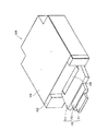
図1は、上記インクジェット式プリンタ100の外観構成を斜め前方から見た斜視図である。このインクジェット式プリンタ100は、上方から見たときに凸形状をした扁平な略直方体の形状をしており、一側面(以下、前面という)側から全ての操作を行うことが可能なように構成されている。すなわち、記録前の記録用紙のセッティングから記録後の記録用紙の取り出し、さらにはインクカートリッジ152の交換等にいたるまで前面側で全て処理することができるので、操作が迅速かつ容易となり、記録効率を向上させることができる。また、上面には可動部や操作部等が無く、上面は平坦に形成されているので、上面への周辺機器等の設置が可能となり、作業空間を有効利用することができる。
【0016】
また、上記前面側に対する背面側の両端もしくは一端の切り欠き部には、各種のケーブルコネクタを配設することが可能なように構成されている。このケーブルコネクタとしては、例えばAC100Vの電源コネクタ、USBポート、パラレル(RS232C)ポート等があり、電源コネクタには電源ケーブルコネクタが、USBポートにはUSBケーブルコネクタが、パラレルポートにはパラレルケーブルコネクタがそれぞれ接続される。このとき、切り欠き部は、各ケーブルコネクタが背面から飛び出ないような大きさに切り欠かれているので、インクジェット式プリンタ100を切り欠き部が無い矩形状の面積とほぼ同等のスペースに設置することができる。
【0017】
さらに、このインクジェット式プリンタ100の前面から切り欠き部の背面までの距離が、切り欠き部の無い直方体状のプリンタの場合の前面から背面までの距離に比べて短くなるので、1枚の基板に前面側のインターフェース部品と背面側のインターフェース部品を実装する場合に、基板の奥行き寸法を小さくすることができ、部品の実装効率を向上させることができると共に、コストダウンを図ることができる。
【0018】
このインクジェット式プリンタ100の後述する図4等に示す用紙搬送部140や記録部150等は、前面側が開放された筐体101及びこの筐体101の前面側にはめ込まれた前枠102により覆われている。筐体101は、例えば金属板の板金加工により、あるいはプラスチックの射出成形により形成され、前枠102は、例えばプラスチックの射出成形により形成されている。筐体101は、例えば底板と上蓋に分割可能に形成されており、底板と上蓋は、ネジ止めもしくはスナップフィット等により締結されるようになっている。前枠102は、筐体101に対してネジ止めもしくはスナップフィット等により締結されるようになっている。スナップフィットによる締結を採用することにより、筐体101や前枠102の取り外し・組み付け作業が簡易になるので、紙詰まり等のエラー解除や部品交換等の修理を迅速に完了させることができる。
【0019】
前枠102の略中央部には、図示矢印aで示す主走査方向(記録ヘッド153の走査方向)を回動軸として図示矢印bで示す方向に開閉自在な排紙される記録用紙を受けるためのスタッカ110が配設され、このスタッカ110の下部には、図示矢印cで示す副走査方向(記録用紙の搬送方向)に抜き差し自在な給紙する記録用紙を収納するためのトレイ120が配設されている。これにより、記録前の記録用紙のセッティングから記録後の記録用紙の取り出しに至るまで前面側で全て処理することができるので、操作が迅速かつ容易となり、記録効率を向上させることができる。以下、図1〜図3を参照してスタッカ110及びトレイ120の詳細を説明する。
【0020】
スタッカ110は、図1に示すように、前枠102に対して閉じているときは格納状態であり、図2に示すように、前枠102に対して開いているときは記録完了後に排紙される記録用紙を受けて載置が可能なように構成されている。これにより、インクジェット式プリンタ100を使用しないときはコンパクトに収納しておくことができる。
【0021】
図2は、上記スタッカ110を開にして記録用紙が受けられるようにした状態を示す斜視図である。このスタッカ110は、3段構成となっており、下部両端が前枠102に回動可能なように取り付けられた基台111と、この基台111に対し出し入れ自在に収納された第1の受け台112と、この第1の受け台112に対し出し入れ自在に収納された第2の受け台113を備えている。このように、スタッカ110を出し入れ自在な3段構成とすることにより、種々のサイズの記録用紙に対しスタッカ110のサイズを合わせることができるので、スペースの有効活用を図ることができる。
【0022】
基台111の両側面の下部には、回動軸となる突起が形成され、基台111の両側面に対向する前枠102の面の下部には、上記突起が回動可能に填め込まれる孔が形成されている。基台111に形成されている突起が前枠102に形成されている孔内にそれぞれ差し込まれることにより、基台111は前枠102に対して略垂直状態から略水平状態までの間を回動し、排紙口を開閉するようになっている。
【0023】
また、基台111の一側面に対向する前枠102の面の上部から内部にかけて、基台111の回動止めとなるロック機構が取り付けられ、基台111の一側面の上部には、上記ロック機構を構成するボールが填め込まれる凹部が形成されている。このロック機構は、ボールが前枠102の面から突き出るように取り付けられ、前枠102の面に対して内部で垂直方向にスライド可能なボールプランジャと、このボールプランジャを前枠102の面方向に垂直に付勢する圧縮コイルバネを備えている。
【0024】
これにより、基台111が開状態のときは、ボールプランジャは圧縮コイルバネにより付勢されて、ボールが前枠102の面から突き出ている。一方、基台111が閉じられてきて基台111の一側面の縁部がボールに対し接触・押圧すると、ボールプランジャがボールとともに前枠102の面から内部にスライドする。そして、基台111が完全に閉じられると、ボールプランジャは圧縮コイルバネにより付勢されて、ボールが前枠102の面から突き出て凹部に填り込み、基台111の閉状態をロックする。したがって、ユーザはロック機構の存在を意識することなく、スタッカ110を容易に開閉させることができる。
【0025】
基台111は、前方に引き出された状態の第1の受け台112の後端部を保持し、第1の受け台112は、前方に引き出された状態の第2の受け台113の後端部を保持している。第1及び第2の受け台112、113が引き出された状態のスタッカ110は、例えばA4サイズの大きさの記録用紙より若干大きく作製されている。これにより、A4サイズ以下の大きさの記録用紙であれば、記録が完了した記録用紙をスタッカ110から落下させることなく整然と積層載置することができる。
【0026】
基台111と第1の受け台112の収納口の両端部には、ガイドとなる突起が設けられ、第1の受け台112と第2の受け台113の両側面には、上記各突起が填め込まれるガイド溝が設けられている。これにより、上記各突起がガイド溝内にてスライドするので、第1の受け台112の基台111に対する出し入れ及び第2の受け台113の第1の受け台112に対する出し入れをスムーズに行うことができる。さらに、上記各突起が収納口にてガイド溝壁に係止されるので、第1の受け台112の基台111に対する引き抜けや、第2の受け台113の第1の受け台112に対する引き抜けを防止することができる。
【0027】
トレイ120は、図1に示すように、前枠102に対して後方の筐体101内に収納された状態にて記録用紙の供給が可能であり、図3に示すように、前枠102に対して前方へ引き出された状態にて記録用紙の補充や交換が可能なように構成されている。これにより、記録用紙不足に対する補充作業を容易に行うことができる。この記録用紙としては、普通紙、専用紙、推奨OHPシート、光沢紙、光沢フィルム、ラベルシート、官製葉書等が利用できる。
【0028】
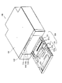
図3は、上記トレイ120を引き出して記録用紙が収納可能なようにした状態を示す斜視図である。このトレイ120は、記録前の記録用紙を積層収納する本体121と、積層収納した記録用紙を1枚ずつ供給するために記録用紙の前部を斜め上方に持ち上げるホッパ122を有している。
【0029】
本体121は、例えばA4サイズの大きさの記録用紙より若干大きく作製されており、記録用紙を内部に配設されている記録用紙の幅方向の位置決め用部材121a及び図示しない長さ方向の位置決め用部材により所定位置に位置決めして積層収納するようになっている。各位置決め用部材は、幅や長さを段階的に調整可能なスライダ及びストッパを備えており、ストッパを外してスライダをスライドさせ、スライダを本体121内に収納された記録用紙の側面に当接させてストッパを掛けることにより、記録用紙を位置決めするようになっている。これにより、複数枚の記録用紙は本体121内にて各位置決め用部材により保持されるので、トレイ120を筐体101内に差し込む際に、多少がたついても記録用紙がずれることはなく、紙詰まり等の給紙エラーを防止することができる。
【0030】
本体121は、前枠102から飛び出ずに面一となるように筐体101内に収納されるため引き出しが困難となるおそれがあるが、前面の下部内側にユーザが指を掛けることができる凹部が形成されており、これによりトレイ120の引き出しを容易に行うことができるようになっている。さらに、本体121の側面をガイドするガイドレールが筐体102内に配設されており、これによりトレイ120の出し入れをスムーズに行うことができるようになっている。
【0031】
ここで、上述したようにトレイ120はインクジェット式プリンタ100の前面側で抜き差しされるため、後述する用紙搬送部140はトレイ120の上方に配設されている。したがって、トレイ120から用紙搬送部140へ記録用紙を供給するには、トレイ120内の記録用紙を一旦持ち上げる必要があり、またトレイ120を抜き差しする際に記録用紙が用紙搬送部140と干渉しないようにするには、トレイ120内の記録用紙を一旦下げる必要があり、このためにホッパ122が配設されている。
【0032】
ホッパ122は、本体121内の前部に配設された用紙支持部122a及びこの用紙支持部122aと一体形成された脚部122bを有しており、脚部122bと本体121の内底面に係止されている付勢部材122cにより、脚部122bの端部を中心に旋回する用紙支持部122aにより記録用紙の前部を斜め上方に持ち上げ、また持ち上げた記録用紙の前部を下げるようになっている。これにより、積層された記録用紙のうち最上層の記録用紙から順に給紙することができる。以上のような構成のトレイ120の上部には用紙搬送部140が配設され、この用紙搬送部140の上方には記録部150が配設されている。以下、図4〜図7を参照して用紙搬送部140及び記録部150並びに搬送駆動部170及び記録駆動部180の詳細を説明する。
【0033】
図4は、前枠102、スタッカ110及びトレイ120を取り外した状態を示す斜視図、図5は、筐体101、前枠102及びスタッカ110を取り外した状態を示す斜視図、図6は、その平面図、図7は、その側面図である。用紙搬送部140は、記録用紙を筐体101内に収納されているトレイ120から前面側に引き出されているスタッカ110まで搬送する機能を有しており、後面側から前面側にかけて以下の部材が順に配設されている。すなわち、トレイ120の上部に配設されている第1紙案内141(図5〜7参照)、上下に対向配置されている給紙ローラ142(図5〜7参照)とパッド143a(図7参照)を有するパッドホルダ143(図7参照)が配設されている。
【0034】
さらに、パッドホルダ143を支持する第2紙案内144(図7参照)、上下に対向配置されている従動ローラ145(図5〜7参照)と紙送りローラ146(図5〜7参照)、記録部150の下部に配設されている第3紙案内147(図5〜7参照)、上下に対向配置されている排紙ギザローラ148(図5〜7参照)と排紙ローラ149(図5、7参照)が配設されている。
【0035】
給紙ローラ142は、ホッパ122により持ち上げられた記録用紙のうち最上層の記録用紙の前部に接触して摩擦により引き込むようになっている。パッドホルダ143に取り付けられているパッド143aは、給紙ローラ142により引き込まれた記録用紙が複数枚あるとき、最上層の記録用紙のみが搬送されるように最上層の記録用紙とそれより下層の記録用紙とを分離して、下層の記録用紙をトレイ120内に戻すようになっている。
【0036】
従動ローラ145と紙送りローラ146は、給紙ローラ142から搬送されてくる記録用紙を挟持して送り出すようになっている。排紙ギザローラ148と排紙ローラ149は、従動ローラ145と紙送りローラ146から搬送されてくる記録用紙を挟持して送り出すようになっている。そして、各紙案内141、144、147は、一部に凸部が形成された平坦な面を有しており、凸部により搬送中の記録用紙面を支持して記録用紙を平坦な状態に維持するようになっている。以上のような用紙搬送部140によれば、トレイ120内に収納されている記録用紙を確実に1枚ずつ引き出してスキュー取りした後、平坦な状態を維持しつつ搬送して最終的にスタッカ110上に排出することができるので、高精度記録された記録用紙を常時得ることができる。
【0037】
記録部150は、主走査方向に移動可能なキャリッジ151(図5〜7参照)、キャリッジ151に対して前後方向に脱着可能に取り付けられたインクカートリッジ152(図5〜7参照)、キャリッジ151に搭載された記録ヘッド153(図7参照)、キャリッジ151の移動を案内するガイド軸154(図5〜7参照)、記録ヘッド153と制御部160の専用コントローラボード等を電気的に接続するフレキシブル配線板155(図5、6参照)等を備えている。
【0038】
キャリッジ151は、インクジェット式プリンタ100が非記録状態であるオフ状態もしくはスタンバイ状態のときは図4〜6に示す待機位置(ホームポジション)に位置しており、記録状態のときはホームポジションを離脱して搬送されてくる記録用紙の両端部間を往復移動するようになっている。インクカートリッジ152は、例えばイエロー、マゼンタ、シアン、ブラックの計4色、さらにはライトイエロー、ライトマゼンタ、ライトシアンの計7色のタンクを備えており、高精細なフルカラー記録が可能なように構成されている。
【0039】
記録ヘッド153は、インクカートリッジ152の上記各色毎のタンクに繋がる複数の圧力発生室とそれらに繋がるノズルを備えており、例えば圧電素子や発熱素子等により圧力発生室内の圧力を変動させて、圧力発生室内に貯留されているインクをノズルから吐出させるようになっている。なお、記録ヘッド153は、ホームポジションに位置しているときは、インク乾燥等によるノズルの目詰まり等を防止するために、キャッピング装置により封止されている。
【0040】
ガイド軸154は、例えば軸受を介して取り付けられているキャリッジ151が摺動可能なように配設されている。フレキシブル配線板155は、キャリッジ151の往復移動の際に、キャリッジ151等と干渉せず、かつ折り曲げられないように、主走査方向に湾曲させて配設されている。以上のような記録部150によれば、キャッピング装置により記録ヘッド153のインク吐出特性は高精度に維持されており、またガイド軸によりキャリッジ151の移動特性も高精度に維持されているので、記録用紙に対し高精度な記録を常時行うことができる。
【0041】
そして、図5、6に示すように、用紙搬送部140を駆動する搬送駆動部170として駆動モータ171及びギア機構172が、用紙搬送部140の一側面側に配設され、記録部150の記録駆動部180として駆動モータ181及びベルト機構182が、記録部150の後方側に配設されている。駆動モータ171としては、例えばステッピングモータが使用されるが、DCモータを使用してもよい。ギア機構172としては、通常のギア輪列が使用されるが、ベルト機構を併用してもよい。なお、このギア機構172の途中には、記録用紙の搬送位置を検出するためのエンコーダが配設されている。
【0042】
また、駆動モータ181としては、例えばDCモータが使用されるが、ステッピングモータを使用してもよい。ベルト機構182としては、歯付きベルトと歯付きプーリが高精度であるため望ましいが、平ベルトとプーリでもよい。なお、このベルト機構182のベルトと平行して、キャリッジ151の移動位置を検出するためのリニアエンコーダが配設されている。
【0043】
以上のような搬送駆動部170及び記録駆動部180によれば、各駆動モータ171、181は(リニア)エンコーダによる検知信号に基づいて駆動制御されるので、記録用紙を高精度に搬送することができるとともに、記録ヘッドを高精度に移動させることができ、記録用紙に対し高精度な記録を常時行い、高精度記録された記録用紙を常時得ることができる。
【0044】
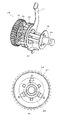
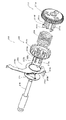
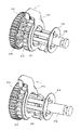
次に、図8〜図10を参照して、このインクジェット式プリンタ100の最も特徴的な部分である補助トレイ130及び補助トレイ駆動手段200を説明する。図8は、補助トレイ130及び補助トレイ駆動手段200の全体構成を示す斜視図、図9は、補助トレイ駆動手段200の主要部分を示す分解斜視図、図10は、補助トレイ駆動手段200の他の主要部分を示す平面図である。
【0045】
補助トレイ130及び補助トレイ駆動手段200は、筺体101に内蔵されている。補助トレイ130は、詳細は後述するが、図8に示す筐体101内の待機位置から紙送りローラ146及び排紙ローラ149を通って筐体101外のディスク出入位置までの間を往復移動可能に配設されている。このように、補助トレイ130はインクジェット式プリンタ100に常備されたものとなっているので、従来のような別体となっている補助トレイを不使用時に管理したり使用時にプリンタ本体内に差し込む手間を省略することができる。
【0046】
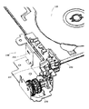
補助トレイ駆動手段200は、搬送駆動部170の駆動モータ171を駆動源としており、補助トレイ130の移動と記録ヘッド153とのペーパーギャップの自動調整(オートペーパーギャップ(APG))の駆動を同期して行う。このように、補助トレイ駆動手段200の駆動源を搬送駆動部170の駆動源である駆動モータ171と兼用することにより、補助トレイ130の送り量と紙送りローラ146の送り量を合わせ、補助トレイ130との干渉による紙送りローラ146のダメージを回避することができる。さらに、補助トレイ130の動作を搬送駆動部170のエンコーダ173により検知することができるので、新たな検知手段を配設する必要が無く、コストを低く抑えることができる。
【0047】
補助トレイ駆動手段200は、図9に示す駆動力切換機構210、駆動力伝達ギア機構220、補助トレイロック機構230と、図10に示すAPG切換レバー機構240を備えている。搬送駆動部170の駆動モータ171の駆動力は、ギア機構172を介して紙送りローラ146に伝達されるが、そのときの駆動力は、紙送りローラ146に嵌合されているギア174を介して駆動力切換機構210にも伝達される。そして、この駆動力切換機構210は、補助トレイ130の移動時には駆動力伝達ギア機構220側に切り換えられるので、駆動モータ171の駆動力は、駆動力伝達ギア機構220を介して補助トレイ130に伝達される。これにより、1つの駆動モータ171で紙送りローラ146の回転と補助トレイ130の移動を実現することができる。以下、補助トレイ駆動手段200の上記各構成要素210、220、230、240のうち、駆動力伝達ギア機構220を図9を参照して、APG切換レバー機構240を図10を参照して、駆動力切換機構210を図11〜図15を参照して、補助トレイロック機構230を図16〜図20を参照して詳細に説明する。
【0048】
駆動力伝達ギア機構220は、駆動モータ171の駆動力を補助トレイ130に伝達する機構であり、図9に示すように、駆動力切換機構210と噛み合う第1のギア221と、この第1のギア221の水平な回転軸を垂直な回転軸に変換する第2及び第3のギア222、223と、この第3のギア223と同軸に配設された第4のギア224及び補助トレイ130に形成されたラックギア133と噛み合う第5のギア225を備えている。これにより、搬送駆動部170の駆動モータ171の駆動力を補助トレイ130に効率良く伝達することができる。
【0049】
APG切換レバー機構240は、補助トレイ130の移動時に記録ヘッド153とのペーパーギャップを自動調整する機構であり、図10に示すように、第1のアーム241及び第2のアーム242を備えている。第1のアーム241は、一端が補助トレイ130のカム溝132に係止されており、第2のアーム242は、一端が第1のアーム241の他端に係止され、中途部が記録ヘッド153と連結され、他端が排紙ギザローラ148と連結されている。そして、補助トレイ130の移動に同期して、第1のアーム241から第2のアーム242を介して記録ヘッド153及び排紙ギザローラ148を移動させるようになっている。
【0050】
すなわち、記録用紙の厚さに比べて補助トレイ130の厚さが厚いので、光ディスクの印刷面と記録ヘッド153のノズル面との距離が、記録用紙の印刷面と記録ヘッド153のノズル面との適正な距離と同一になるように、記録ヘッド153を上昇させるようになっている。また、光ディスクの印刷面が排紙ギザローラ148と接触して傷付いてしまわないように、排紙ギザローラ148を上方へ退避させるようになっている。なお、従動ローラ145は、プラスチックかゴム等により作成されており、光ディスクの印刷面と接触しても傷付くことはないので退避させる必要はないが、下方に付勢されているため、補助トレイ130は、例えば3.92N(400gf)以上の力で挿入して押し上げる必要がある。また、従動ローラ145を保持する紙案内における従動ローラ145間には爪部が形成されているが、この爪部との接触を回避するため、補助トレイ130に工夫が施されており、この詳細については後述する。
【0051】
なお、図示していないが、補助トレイ130がディスク出入位置に位置しているときに、例えばユーザにより待機位置の方向へ押されたことを検知する検知手段を備えている。この検知手段から検知信号を受けたとき、補助トレイ130を待機位置へ自動的に戻すようにすることにより、補助トレイ130がディスク出入位置から待機位置の方向へ無理に押し込まれることを防止することができるので、紙送りローラ146や排紙ローラ149及び記録ヘッド153が補助トレイ130と衝突して傷付いたり変形したりしてしまうことが無くなる。この検知手段は、例えば放射状に複数のスリットが形成され、補助トレイ130の移動に連動して回転する回転円盤と、この回転円盤の両面側に配設され、回転円盤の回転により変化する光量を検出するフォトインタラプタを備えている。
【0052】
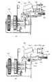
図11(A)、(B)は、上記駆動力切換機構210を示す斜視図及び側面図、図12は、その分解斜視図、図13は、それを反対側から見た分解斜視図である。この駆動力切換機構210は、駆動モータ171の駆動力の伝達を駆動力伝達ギア機構220側に切り換える機構であり、図11〜図13に示すように、主要構成要素である第1の伝達ギア211、第2の伝達ギア212及びレバー213が、圧縮バネ214及び抜け止め215とともに回転軸216に嵌入された構成となっている。すなわち、回転軸216には、第1の伝達ギア211、圧縮バネ214、第2の伝達ギア212、レバー213、抜け止め215の順に嵌入されている。
【0053】
第1の伝達ギア211は、図12及び図13に示すように、紙送りローラ146に嵌合されているギア174に常時噛み合うギア部211aと、このギア部211aの一端面から軸方向に突き出るように一体形成され、回転軸216が嵌入される円筒状の軸部211bと、同様にギア部211aの端面から軸方向に突き出るように、かつ軸部211bの周りに等間隔で一体形成された3本の棒状の係止部211cを有している。軸部211bの外周面における各係止部211cの間には、第2の伝達ギア212の回転は規制しつつ摺動は自在とする軸方向に延びる3つの規制部211dが一体形成されている。係止部211cは、先端が楔形の鉤状に形成されており、カンチレバーのように径方向に撓むようになっている。
【0054】
第2の伝達ギア212は、図12及び図13に示すように、駆動力伝達ギア機構220の第1のギア221に噛み合い可能なギア部212aと、このギア部212aの一端面から軸方向に突き出るように一体形成され、第1の伝達ギア211の軸部211bが嵌入される円筒状の軸部212bを有している。軸部212bには、第1の伝達ギア211の3本の係止部211cと3つの規制部211dが挿入可能な6つのスリット部212cが形成されている。
【0055】
レバー213は、図12及び図13に示すように、第1の伝達ギア211の係止部211c周りに挿入される穴213aが形成された回転部213bと、回転部213bの外縁から外側に突き出るように一体形成された停止部213cと、停止部213cの略反対側の回転部213bの外縁から外側に突き出るように一体形成された押圧部213dを有している。停止部213cは、キャリッジ151に当接してレバー213を回転停止させるように作用する。押圧部213dは、キャリッジ151に当接し押圧されてレバー213とともに第2の伝達ギア212を摺動させるように作用する。
【0056】
以上のような構成において、駆動力切換機構210の組立手順を説明する。先ず、第1の伝達ギア211の係止部211cの楔形の鉤状に形成されている先端に圧縮バネ214の一端を押圧し、各係止部211cを内側に撓ませて、圧縮バネ214を各係止部211c周りに嵌入する。このとき、内側に撓んだ各係止部211cは、弾性力により元の状態に復元するので、圧縮バネ214の他端は、係止部211cの楔形の鉤状に形成されている先端に係止され、圧縮バネ214は第1の伝達ギア211から抜けなくなる。
【0057】
同様に、第1の伝達ギア211の係止部211cの楔形の鉤状に形成されている先端に第2の伝達ギア212のギア部212aの他端面を押圧し、各係止部211cを内側に撓ませる。そして、第1の伝達ギア211の各規制部211d及び各係止部211cを第2の伝達ギア212の各スリット部212cに挿入し、第2の伝達ギア212の軸部212bを各係止部211c周りに嵌入する。このとき、内側に撓んだ各係止部211cは、弾性力により元の状態に復元するので、ギア部212aの一端面は、係止部211cの楔形の鉤状に形成されている先端に係止され、第2の伝達ギア212も第1の伝達ギア211から抜けなくなる。そして、第2の伝達ギア212は、各スリット部212cに挿入された各規制部211dにより、第1の伝達ギア211とともに回転可能であって、軸部211bに沿って摺動自在に保持される。
【0058】
さらに同様に、第1の伝達ギア211の係止部211cの楔形の鉤状に形成されている先端にレバー213の回転部213bを押圧し、各係止部211cを内側に撓ませて、回転部213bを各係止部211c周りに嵌入する。このとき、内側に撓んだ各係止部211cは、弾性力により元の状態に復元するので、回転部213bは、係止部211cの楔形の鉤状に形成されている先端に係止され、レバー213も第1の伝達ギア211から抜けなくなる。そして、レバー213は、ラジアル方向に物理的に拘束されている同期する第1の伝達ギア211と第2の伝達ギア212の間に圧縮バネ214に付勢されて挟持されることになるので、従来必要であった輪止め等を用いなくても滑りを防止することができ、より確実な動作が得られ、荷重を低減することができる。
【0059】
最後に、第1の伝達ギア211の軸部211bに回転軸216を挿入し、第2の伝達ギア212の軸部212bに抜け止め215を嵌入することにより、最終的に図11に示すような駆動力切換機構210が完成する。このような構成の駆動力切換機構210の動作を図11、図14及び図15を参照して説明する。
【0060】
図14は、駆動力切換機構210とキャリッジ151の関係を示す平面図、図15は、そのときの駆動力切換機構210の状態を示す斜視図である。図14(A)に示すように、キャリッジ151がホームポジションから離れているときは、第2の伝達ギア212は、圧縮バネ214により駆動力伝達ギア機構220の第1のギア221から離間する方向に付勢されている。さらに、図11(A)に示すように、レバー213の押圧部213dは、キャリッジ151とは当接しない位置に回転位置決めされている。したがって、補助トレイ130には搬送駆動部170の駆動モータ171の駆動力は伝達されない。
【0061】
そして、補助トレイ130を使用するときは、先ず、搬送駆動部170の駆動モータ171が一旦逆転することにより、図15(A)に示すように、レバー213の押圧部213dは、キャリッジ151と当接する位置に回転位置決めされる。そして、キャリッジ151がホームポジションに戻ってくるときにレバー213の押圧部213dに当接して押圧し、レバー213を第2の伝達ギア212とともにキャリッジ151の移動方向に平行スライドさせる。
【0062】
そして最終的に、図14(B)及び図15(B)に示すように、キャリッジ151は、第2の伝達ギア212を駆動力伝達ギア機構220の第1のギア221と噛み合わせる。したがって、補助トレイ130には搬送駆動部170の駆動モータ171の駆動力が伝達される。なお、第2の伝達ギア212と駆動力伝達ギア機構220の第1のギア221との位相ずれは、レバー213の押圧部213dが撓むことにより吸収されるようになっている。このように、レバー213をキャリッジ151の移動方向に平行スライドさせることができるので、レバー213と係止部211c等間での片当たり等による不具合を防止して、補助トレイ130への駆動力の伝達を確実に切り換えることができる。
【0063】
図16は、上記補助トレイロック機構230を前方側から見た斜視図、図17は、それを後方側から見た斜視図、図18は、その分解斜視図である。この補助トレイロック機構230は、補助トレイ130を待機位置で機械的にロックする機構であり、図16〜図18に示すように、ロックレバー231、レバー検出器232及びホルダ233等を備えている。補助トレイロック機構230は、図16及び図17に示すように、駆動力切換機構210と補助トレイ130の間に配設されており、駆動力切換機構210に連動して動作するようになっている。このような補助トレイロック機構230を設けることにより、記録用紙の自動給紙と補助トレイ130の移動との切り分けが可能となる。
【0064】
ロックレバー231は、図18に示すように、略F字状の上部先端がレバー検出部232に検出される被検出部231a、中部先端が補助トレイ130をロックするロック部231b、下部先端が駆動力切換機構210の抜け止め215に押圧される押圧部231cとして機能するように、略中央部に揺動中心となる揺動軸231dが突設形成されている。レバー検出器232は、受発光部232a、232bを有するフォトインタラプタであり、受発光部232a、232b間にロックレバー231の被検出部231aが出入することにより補助トレイ130のロック状態を検出するようになっている。ホルダ233は、ロックレバー231を揺動自在に支持するレバー支持部233aと、レバー検出器232を保持する検出器保持部233bを有している。
【0065】
以上のような構成において、補助トレイロック機構230の組立手順を説明する。先ず、ロックレバー231の揺動軸231dにねじりコイルバネ234を填め込み、この揺動軸231dをホルダ233のレバー支持部233aに填め込む。そして、ねじりコイルバネ234の一端をレバー支持部233aに係止し、他端をロックレバー231に係止する。これにより、ロックレバー231は、揺動軸231dを中心に揺動自在に支持されることになる。
【0066】
次に、レバー検出器232をホルダ233の検出器保持部233bに固定し、駆動力切換機構210と補助トレイ130の間に配設することにより、最終的に図16及び図17に示すような補助トレイロック機構230が完成する。これにより、ロックレバー231の被検出部231aが揺動によりレバー検出器232の受発光部232a、232b間に出入可能となる。このような構成の補助トレイロック機構230の動作を図19及び図20を参照して説明する。なお、図19(B)は図19(A)の一部を取り除いた状態を示す図である。
【0067】
補助トレイ130が待機位置に位置しているときは、図19(A)に示すように、ロックレバー231はねじりコイルバネ234に付勢されている。このため、図19(B)に示すように、被検出部231aはレバー検出器232の受発光部232a、232b間から離間し、ロック部231bは補助トレイ130に形成されているロック穴134内に填り込んでいる。したがって、補助トレイ130は待機位置にロックされており、補助トレイ130がロック状態にあることはレバー検出器232からのオン信号を検出することにより検知することができる。
【0068】
補助トレイ130を使用するために、キャリッジ151がホームポジションに戻ってくるときに駆動力切換機構210のレバー213の押圧部213dに当接して押圧し、レバー213を第2の伝達ギア212とともにキャリッジ151の移動方向に平行スライドさせると、同時に抜け止め215もキャリッジ151の移動方向に平行スライドする。このとき、押圧部231cは抜け止め215に当接して押圧されるので、ロックレバー231は図示右回りに回転する。
【0069】
このため、図20(A)に示すように、被検出部231aはレバー検出器232の受発光部232a、232b間に入り込み、ロック部231bは補助トレイ130に形成されているロック穴134から離間する。したがって、補助トレイ130のロックが駆動力切換機構210の切換動作に同期して解除され、補助トレイ130がロック解除状態にあることは、レバー検出器232からのオフ信号を検出することにより検知することができる。
【0070】
その後、キャリッジ151がホームポジションから離間すると、第2の伝達ギア212とともにレバー213は元の位置に戻り、同時に抜け止め215も元の位置に戻るため、ロックレバー231はねじりコイルバネ234に付勢されて図示左回りに回転し元の位置に戻ろうとする。ところが、補助トレイ130が移動開始しているため、ロック部231bは補助トレイ130の平坦な裏面に当接した状態となり、ロックレバー231の回転が止まるので、被検出部231aはレバー検出器232の受発光部232a、232b間に入り込んだままとなる。したがって、補助トレイ130が待機位置から離間しているときは、レバー213の状態に拘わらずレバー検出器232からのオフ信号を常時検出することができるので、補助トレイ130がロック解除状態にあることを検知することができる。次に、上記補助トレイ130を図21を参照して詳細に説明する。
【0071】
図21は、補助トレイ130を示す斜視図である。この補助トレイ130は、プラスチックで矩形板状に形成されており、表面の図示手前側には1枚の光ディスクを載置・収納可能な円形状のディスク用凹部131が形成され、図示後方左側面側にはAPG切換レバー機構240の第1のアーム241が係止されるカム溝132が形成され、図示左側面には駆動力伝達ギア機構220の第5のギア225と噛み合うラックギア133が形成されている。
【0072】
このような構成の補助トレイ130によれば、ディスク用凹部131内に光ディスクを収納することができるので、記録中の光ディスクのずれを防止することができる。また、カム溝132によりAPGを機械的に制御することができ、ラックギア133により移動も機械的に制御することができるので、高精度な記録を維持することができる。この補助トレイ130の特徴的な部分として、溝部135とAPG規制レバー137があり、以下に説明する。
【0073】
図21に示すように、補助トレイ130の特徴的な部分である溝部135は、ディスク用凹部131におけるトレイ先端側の内壁131aからトレイ先端手前までにかけて、ディスク用凹部131と略同一の深さで4つが所定間隔で形成されている。これらの溝部135は、図22に示すように、従動ローラ145を保持する紙案内における従動ローラ145間に形成されている爪部145aの位置に対応するように形成されている。
【0074】
これにより、補助トレイ130がディスク出入位置から待機位置へ戻るとき、先ず従動ローラ145が内壁131aを昇って溝部135と溝部135の間の丘部136上を通るので、続く爪部145aは少し持ち上げられた状態で溝部135上方を通る。このように、補助トレイ130に爪部145aが逃げる溝部135を設けることにより、従動ローラ145を上方へ退避させなくても、内壁131aが爪部145aと接触することを回避することができる。
【0075】
図21に示すように、補助トレイ130の特徴的な部分であるAPG規制レバー137は、カム溝132の後端を跨いでトレイ後端に沿うように配設されている。このAPG規制レバー137は、図23に示すように、一対の案内棒137aが一定間隙を開けた状態を保てるように、案内棒137aの一端に旋回軸137bが取り付けられ、さらに一対の案内棒137aがカム溝132を含むトレイ後端部を挟み込んだ位置からカム溝132の延長線上の位置まで旋回できるように、トレイ後端部のカム溝132の図示左側に形成された軸溝137cに旋回軸137bが填め込まれている。
【0076】
ここで、APGポジションを確保するには、第1のアーム241の一端は、補助トレイ130が待機位置からディスク出入位置まで移動する間、カム溝132に係止されている必要があるが、そのためにはカム溝132の長さ、すなわち補助トレイ130の長さを非常に長く形成する必要がある。しかし、補助トレイ130の長さを非常に長く形成すると、インクジェット式プリンタ100の筐体101の奥行きも長くなって大型化してしまうことになる。
【0077】
そこで、図24に示すように、第1のアーム241の一端がカム溝132の先端(補助トレイ130の待機位置)から後端に達するまでは、APG規制レバー137はカム溝132を含むトレイ後端部を挟み込んだ位置に待機する。そして、図25に示すように、第1のアーム241の一端がカム溝132の後端に達した後は、APG規制レバー137がカム溝132の延長線上の位置になるまで、APG規制レバー137は第1のアーム241の一端に押されて旋回しつつ、第1のアーム241の一端をカム溝132の代わりに係止する。これにより、補助トレイ130の長さを非常に長く形成しなくても、補助トレイ130が待機位置からディスク出入位置まで移動する間、APGポジションを確保することができる。したがって、補助トレイ130の長さを必要以上に長く形成する必要がなく、インクジェット式プリンタ100を小型化することができる。
【0078】
以上のような構成のインクジェット式プリンタ100において、先ず、記録用紙に記録する場合の動作を説明する。なお、インクジェット式プリンタ100とテレビジョン・システムやコンピュータ等との接続配線や電源プラグの接続は既に完了しているものとする。先ず、ユーザは、図1に示す状態で指で取出ボタン103を押した後、指をトレイ120の底面に設けられている凹部に掛けて引っ張ることにより、図2に示すようにトレイ120を前方へ引き出す。
【0079】
続いて、トレイ120の本体111内の所定位置に複数枚の記録用紙を積層した状態で収納した後、トレイ120を後方へ押し込んでセットする。このとき、記録用紙の前部はホッパ112により斜め上方に持ち上げられ、最上部の記録用紙の前部先端が給紙ローラ142に接触する。次に、ユーザは、指をスタッカ110の上部に掛けて引っ張ることにより、図3に示すようにスタッカ110を前方へ引き出す。そして、インクジェット式プリンタ100をスタンバイ状態にし、テレビジョン・システムやコンピュータ等から記録指令を入力する。
【0080】
すると、図7に示すように、トレイ120内の最上部の1枚の記録用紙Pは、第1紙案内141と第2紙案内144に案内されつつ、給紙ローラ142の回転により副走査方向である前方へ引き出されて給紙ローラ142とパッド143aとの間に挟持されて更に前方へ送り出される。このとき、記録用紙Pがトレイ120内の最上部の1枚のみでなく複数枚あるときは、最上部の記録用紙Pとそれより下部の記録用紙Pとがパッド143aにより分離され、最上部の記録用紙Pのみが給紙ローラ142とパッド143aとの間に挟持されて更に前方へ送り出され、下部の記録用紙Pはトレイ120内に戻される。
【0081】
そして、最上部の記録用紙Pは、従動ローラ145と紙送りローラ146との間に挟持されて更に前方へ送り出される。その記録用紙Pが第3紙案内147に達すると、キャリッジ151の主走査方向への移動が開始される。すなわち、ホームポジションに位置してしたキャリッジ151は、ホームポジションを離脱して搬送されてくる記録用紙Pの両端部間を往復移動する。そして、記録ヘッド153は、副走査方向に搬送されつつある記録用紙Pに対し例えば圧電素子により圧力発生室内の圧力を変動させて、圧力発生室内に貯留されているインクをノズルから吐出して、記録用紙P上に所定の記録情報を記録する。
【0082】
このときの記録ヘッド153の走査タイミングやインク吐出タイミングは、制御部160の専用コントローラボード等により制御され、高精度なインクドット制御、ハーフトーン処理等が実行されるようになっている。そして、その記録用紙Pは、排紙ギザローラ148と排紙ローラ149との間に挟持されて更に前方へ送り出され、最終的に記録が完了した記録用紙Pはスタッカ110上に排紙される。
【0083】
次に、補助トレイ130及び補助トレイ駆動手段200を使用して光ディスクの表面に印刷するときの動作例を図26及び図27のフローチャートで説明する。スタンバイ状態では、補助トレイ130は、待機位置に位置している。ユーザがトレイイジェクトボタンを押下すると、搬送駆動部170の駆動モータ171が逆転して駆動力切換機構210のレバー213の押圧部213dをキャリッジ151と当接する位置に回転位置決めする(ステップS1)。
【0084】
続いて、キャリッジ151がホームポジションに戻ってくるときにレバー213の押圧部213dに当接して押圧し、レバー213を第2の伝達ギア212とともにキャリッジ151の移動方向に平行スライドさせる(ステップS2)。そして、キャリッジ151がレバー213の押圧部213dを押圧している状態で、駆動モータ171が逆転して第2の伝達ギア212を微小回転させることで、第2の伝達ギア212を駆動力伝達ギア機構220の第1のギア221と噛み合わせる(ステップS3)。
【0085】
第2の伝達ギア212と第1のギア221が噛み合った後、キャリッジ151がレバー213の押圧部213dをさらに押圧することにより、第2の伝達ギア212を第1のギア221に完全に噛み合わせる(ステップS4)。そして、補助トレイロック機構230のレバー検出器232からの信号を検出し、補助トレイ130がロック解除状態にあるか否かを確認する(ステップS5)。補助トレイ130がロック解除状態にないときは、ステップS2に戻って上述した動作を繰り返す。このリトライ動作は、回数制限、例えばリトライ3回でエラー表示等を掛けるようにしてもよい。
【0086】
一方、ステップS5において、補助トレイ130がロック解除状態にあるときは、駆動モータ171が正転して補助トレイ130が従動ローラ145を押し上げるまで補助トレイ130を低速、例えば0.83ipsで移動させる(ステップS6)。そして、補助トレイ130が排紙ローラ149に達したら、補助トレイ130を比較的高速、例えば3ipsでディスク出入位置まで移動させる(ステップS7)。なお、記録ヘッド153及び排紙ギザローラ148は、補助トレイ130の移動に同期してAPG切換レバー機構240の第1アーム241から第2アーム242を介して移動する。
【0087】
その後、ユーザが光ディスクを補助トレイ130にセットしてトレイセットボタンを押下すると、搬送駆動部170の駆動モータ171が逆転して駆動力切換機構210のレバー213の押圧部213dをキャリッジ151と当接する位置に回転位置決めする(ステップS11)。続いて、キャリッジ151がホームポジションに戻ってくるときにレバー213の押圧部213dに当接して押圧し、レバー213を第2の伝達ギア212とともにキャリッジ151の移動方向に平行スライドさせる(ステップS12)。
【0088】
そして、キャリッジ151がレバー213の押圧部213dを押圧している状態で、駆動モータ171が逆転して第2の伝達ギア212を微小回転させることで、第2の伝達ギア212を駆動力伝達ギア機構220の第1のギア221と噛み合わせる(ステップS13)。第2の伝達ギア212と第1のギア221が噛み合った後、キャリッジ151がレバー213の押圧部213dをさらに押圧することにより、第2の伝達ギア212を第1のギア221に完全に噛み合わせる(ステップS14)。
【0089】
そして、駆動モータ171が逆転して補助トレイ130が紙送りローラ146から外れる手前まで補助トレイ130を比較的高速、例えば3ipsで移動させる(ステップS15)。そして、補助トレイ130が紙送りローラ146から外れる手前に達したら、補助トレイ130を低速、例えば0.83ipsで待機位置まで移動させる(ステップS16)。
【0090】
そして、補助トレイロック機構230のレバー検出器232からの信号を検出し、補助トレイ130がロック状態にあるか否かを確認する(ステップS17)。補助トレイ130がロック状態にあるときは、処理を終了する。一方、ステップS17において、補助トレイ130がロック状態にないときは、キャリッジ151がホームポジションに戻ってくるときにレバー213の押圧部213dに当接して押圧し、レバー213を第2の伝達ギア212とともにキャリッジ151の移動方向に平行スライドさせる(ステップS18)。
【0091】
そして、キャリッジ151がレバー213の押圧部213dを押圧している状態で、駆動モータ171が逆転して第2の伝達ギア212を微小回転させることで、第2の伝達ギア212を駆動力伝達ギア機構220の第1のギア221と噛み合わせる(ステップS19)。第2の伝達ギア212と第1のギア221が噛み合った後、キャリッジ151がレバー213の押圧部213dをさらに押圧することにより、第2の伝達ギア212を第1のギア221に完全に噛み合わせる(ステップS20)。
【0092】
その後、補助トレイロック機構230のレバー検出器232からの信号を検出し、補助トレイ130がロック状態にあるか否かを確認する(ステップS21)。補助トレイ130がロック状態にないときは、ステップS18に戻って上述した動作を繰り返す。このリトライ動作は、回数制限、例えばリトライ3回でエラー表示等を掛けるようにしてもよい。一方、ステップS21において、補助トレイ130がロック解除状態にあるときは、全ての処理を終了する。
【0093】
その後、補助トレイ130は、待機位置から印刷開始位置まで移動し、光ディスクの印刷が開始される。光ディスクの印刷が終了して補助トレイ130がディスク出入位置まで移動したら、ユーザは光ディスクを補助トレイ130から取り出してトレイセットボタンを押下する。これにより、補助トレイ130は、ディスク出入位置から待機位置まで移動し、記録ヘッド153及び排紙ギザローラ148は元の位置へ移動する。その後、駆動モータ171が停止し、スタンバイ状態となる。このような駆動力切換機構210を有する補助トレイ駆動手段200を使用することにより、補助トレイ130を高精度に移動させることができるので、光ディスクの表面の印刷を高精度に行うことができる。
【0094】
以上、本発明を種々の実施形態に関して述べたが、本発明は以上の実施形態に限られるものではなく、特許請求の範囲に記載された発明の範囲内で、他の実施形態についても適用されるのは勿論である。例えば、記録装置としてプリンタを例に説明したが、これに限られるものではなく、例えばファクシミリ装置やコピー装置等の記録装置にも適用可能である。
【図面の簡単な説明】
【図1】 本発明の実施の形態に係る記録装置の1つであるインクジェット式プリンタの構成例を斜め前方から見た斜視図である。
【図2】 図1のインクジェット式プリンタのスタッカを開にして記録用紙が受けられるようにした状態を示す斜視図である。
【図3】 図1のインクジェット式プリンタのトレイを引き出して記録用紙が収納可能なようにした状態を示す斜視図である。
【図4】 図1のインクジェット式プリンタの前枠、スタッカ及びトレイを取り外した状態を示す斜視図である。
【図5】 図1のインクジェット式プリンタの筐体、前枠及びスタッカを取り外した状態を示す斜視図である。
【図6】 図5のインクジェット式プリンタの平面図である。
【図7】 図5のインクジェット式プリンタの側面図である。
【図8】 図1のインクジェット式プリンタの補助トレイ及び駆動力切換機構を有する補助トレイ駆動手段の全体構成を示す斜視図である。
【図9】 図8の駆動力切換機構を有する補助トレイ駆動手段の主要部分を示す分解斜視図である。
【図10】 図8の補助トレイ駆動手段の他の主要部分を示す平面図である。
【図11】 図8の補助トレイ駆動手段の駆動力切換機構を示す斜視図及び側面図である。
【図12】 図11の駆動力切換機構の分解斜視図である。
【図13】 図12を反対側から見た駆動力切換機構の分解斜視図である。
【図14】 図11の駆動力切換機構とキャリッジの関係を示す平面図である。
【図15】 図14の駆動力切換機構の状態を示す斜視図である。
【図16】 図8の補助トレイ駆動手段の補助トレイロック機構を前方側から見た斜視図である。
【図17】 図16の補助トレイロック機構を後方側から見た斜視図である。
【図18】 図16の補助トレイロック機構の分解斜視図である。
【図19】 図16の補助トレイロック機構の動作を示す第1の図である。
【図20】 図16の補助トレイロック機構の動作を示す第1の図である。
【図21】 図8の補助トレイを示す斜視図である。
【図22】 図8の補助トレイの特徴的な第1部分を示す平面図である。
【図23】 図8の補助トレイの特徴的な第2部分を示す分解斜視図である。
【図24】 図23の第2部分の動作を示す第1の平面図である。
【図25】 図23の第2部分の動作を示す第2の平面図である。
【図26】 図8の補助トレイ及び補助トレイ駆動手段を使用して光ディスクの表面に印刷するときの動作例を示す第1のフローチャートである。
【図27】 図8の補助トレイ及び補助トレイ駆動手段を使用して光ディスクの表面に印刷するときの動作例を示す第2のフローチャートである。
【符号の説明】
100 インクジェット式プリンタ、101 筐体、102 前枠、103 取出ボタン、110 スタッカ、111 基台、112 第1の受け台、113第2の受け台、120 トレイ、121 本体、122 ホッパ、130 補助トレイ、131 ディスク用凹部、132 カム溝、133 ラックギア、134 ロック穴、135 溝部、136 丘部、137 APG規制レバー、140 用紙搬送部、141 第1紙案内、142 給紙ローラ、143 パッドホルダ、144 第2紙案内、145 従動ローラ、145a 爪部、146 紙送りローラ、147 第3紙案内、148 排紙ギザローラ、149 排紙ローラ、150 記録部、151 キャリッジ、152 インクカートリッジ、153 記録ヘッド、154 ガイド軸、155 フレキシブル配線板、160 制御部、170 搬送駆動部、171 駆動モータ、172 ギア機構、173エンコーダ、180 記録駆動部、181 駆動モータ、182 ベルト機構、200 補助トレイ駆動手段、210 駆動力切換機構、211 第1の伝達ギア、212 第2の伝達ギア、213 レバー、214 圧縮バネ、215 抜け止め、216 回転軸、220 駆動力伝達ギア機構、230 補助トレイロック機構、231 ロックレバー、232 レバー検出器、233 ホルダ、234 ねじりコイルバネ、240 APG切換レバー機構、241 第1のアーム、242 第2のアーム
[0001]
BACKGROUND OF THE INVENTION
The present invention relates to a driving unit for a transport mechanism system of an auxiliary tray that assists recording on a recording medium by mounting and transporting a recording medium that cannot be transported, and a recording apparatus including the driving unit.
[0002]
[Prior art]
In general, an ink jet printer, which is one of recording apparatuses, includes a recording head mounted on a carriage that reciprocates in the main scanning direction, and a sheet conveying unit that intermittently conveys recording sheets by a set amount in the sub scanning direction. ing. The recording head is moved in the main scanning direction while conveying the recording paper in the sub-scanning direction, and information is recorded by ejecting ink droplets from the recording head onto the recording paper.
[0003]
A new recording sheet is stacked in a detachable tray disposed on the back side of the printer main body, one end is lifted by a hopper, and the uppermost recording sheet is pulled out and fed by a sheet feeding roller. Then, the fed recording paper is conveyed by a paper feed roller to perform the above recording, and the recorded recording paper is discharged onto an openable / closable stacker provided on the front side of the printer main body. It has become.
[0004]
Usually, the paper feed roller and the paper feed roller are driven by the same driving motor with the transmission of driving force switched. The switching mechanism includes a switching gear that is non-rotatably attached to the paper feed roller and is slidable in the axial direction, a fulcrum portion that is in contact with the printer main body frame with the paper feed roller as a center, and the other end of the carriage. The switch lever formed in the bar shape used as the contact part which contacts a part is provided.
[0005]
In the switching mechanism having such a configuration, the switching gear is urged by the spring and is held at the non-engagement position with respect to the driving force transmission gear to the paper feed roller. When the paper feed roller rotates in the direction opposite to the paper feed direction, the switching lever rotates to a position where it comes into contact with a part of the carriage, and when it moves to the standby position of the carriage, it comes into contact with a part of the carriage to drive the switching gear. Displace to the meshing position with the force transmission gear. On the other hand, when the carriage is released from the standby position, the switching gear is urged by the spring together with the switching lever and is displaced to the non-engagement position with respect to the driving force transmission gear. Then, when the paper feed roller rotates in the paper feed direction, the switching lever rotates to a position where it is retracted from the carriage (see Patent Document 1).
[0006]
[Patent Document 1]
Japanese Patent Laid-Open No. 10-129057
[0007]
[Problems to be solved by the invention]
In recent years, since optical disks such as CD-RW / R and DVD-RW / R that can be personally recorded have become widespread, ink jet printers capable of printing on the surface have been developed. When printing on the surface of an optical disk, the optical disk cannot be supplied and transported like normal recording paper. Therefore, the optical disk is stored in an auxiliary tray and printed on the surface of the optical disk by transporting this auxiliary tray. ing.
[0008]
Such an ink jet printer requires driving means for the transport mechanism system of the auxiliary tray. However, driving means for the transport mechanism system of the recording paper is already provided, and it is possible to add the auxiliary tray driving means. It is not desirable from the viewpoint of component cost and arrangement space. On the other hand, when the above-described switching mechanism is applied to the auxiliary tray driving means, the switching lever has a fulcrum portion with one end in contact with the printer main body frame and a contact portion with the other end in contact with a part of the carriage with the paper feed roller as the center. Therefore, the switching gear is pressed obliquely with respect to the axial direction of the paper feed roller. Therefore, the inner peripheral portion of the switching gear may come into contact with the outer peripheral portion of the paper feed roller, and the switching gear cannot be slid along the paper feed roller and the auxiliary tray may not be driven. There is.
[0009]
SUMMARY An advantage of some aspects of the invention is that it provides an auxiliary tray driving unit and a recording apparatus that can reliably drive a conveyance mechanism system of an auxiliary tray.
[0010]
[Means for Solving the Problems]
To achieve the above object, in the auxiliary tray driving means according to the present invention, a recording medium that cannot be conveyed by the driving means for conveying the sheet-like recording medium is placed and conveyed, so that the recording medium that cannot be conveyed A driving mechanism for driving the auxiliary tray for assisting recording on the auxiliary tray, the driving force switching mechanism switching the transmission of the driving force of the driving means for conveying the sheet-like recording medium to the conveying mechanism system of the auxiliary tray; And a driving force transmission mechanism for transmitting the driving force from the driving force switching mechanism to the auxiliary tray. Thereby, since the drive means of the conveyance mechanism system of the sheet-like recording medium can also be used, the number of parts can be reduced and the cost can be reduced.
[0011]
The driving force switching mechanism is characterized in that the transmission of the driving force is switched by sliding parallel to the moving direction by the movement of the carriage on which the recording head is mounted. As a result, the operation of the main part of the driving force switching mechanism can always be held parallel to the scanning direction of the recording head, so that it is possible to prevent problems caused by contact between the main parts of the driving force switching mechanism and The transmission of the driving force to the tray transport mechanism system can be switched reliably.
[0012]
The driving force transmission mechanism transmits a driving force by a gear formed on the auxiliary tray. Thereby, since a driving force can be mechanically transmitted to the auxiliary tray, the auxiliary tray can be moved with high accuracy.
[0013]
In order to achieve the above object, in the recording apparatus according to the present invention, the recording medium that can be transported by the driving means for transporting the sheet-like recording medium and is stored in the tray is taken out and recorded, and the sheet-like recording is performed. A recording apparatus that records a recording medium stored in an auxiliary tray, which cannot be conveyed depending on a driving unit that conveys the medium, while conveying the auxiliary tray together with the auxiliary tray, and includes the auxiliary tray driving unit. Thereby, a recording apparatus that exhibits the above-described effects can be provided. Further, at least the tray and the auxiliary tray can be moved in and out on the same apparatus side surface. Thus, a front operation type recording apparatus that exhibits the above-described effects can be provided.
[0014]
DETAILED DESCRIPTION OF THE INVENTION
1 to 8 are views showing an external configuration and an internal structure of an ink jet printer which is one of recording apparatuses according to an embodiment of the present invention. The inkjet printer 100 includes a stacker 110 (see FIGS. 1 to 3), a tray 120 (see FIGS. 1 to 3), a paper transport unit 140 (see FIGS. 4 to 7), a recording unit 150 (see FIGS. 4 to 7), The control unit 160 (see FIGS. 5 and 6), the conveyance drive unit 170 (see FIGS. 5 and 6), the recording drive unit 180 (see FIGS. 5 and 6), and the auxiliary tray 130 (see FIG. 8) which is a more characteristic part. And auxiliary tray driving means 200 (see FIG. 8). And these are the structures attached and covered by the housing | casing 101 (refer FIGS. 1-3) and the front frame 102 (refer FIGS. 1-3). Hereinafter, the main components will be sequentially described with reference to the drawings.
[0015]
FIG. 1 is a perspective view of the external configuration of the ink jet printer 100 as viewed obliquely from the front. The ink jet printer 100 has a flat, substantially rectangular parallelepiped shape that is convex when viewed from above, and is configured so that all operations can be performed from one side surface (hereinafter referred to as the front surface). Has been. In other words, since all processing can be performed on the front side from the setting of the recording paper before recording to the removal of the recording paper after recording and the replacement of the ink cartridge 152, the operation becomes quick and easy, and the recording efficiency is improved. Can be improved. In addition, since there are no movable part or operation part on the upper surface and the upper surface is formed flat, it is possible to install peripheral devices on the upper surface, and the working space can be used effectively.
[0016]
In addition, various cable connectors can be arranged at the notches at both ends or one end on the back side with respect to the front side. Examples of the cable connector include an AC 100V power connector, a USB port, and a parallel (RS232C) port. The power connector includes a power cable connector, the USB port includes a USB cable connector, and the parallel port includes a parallel cable connector. Each is connected. At this time, since the cutout portion is cut out in such a size that each cable connector does not protrude from the back surface, the ink jet printer 100 is installed in a space substantially equal to a rectangular area without the cutout portion. be able to.
[0017]
Further, since the distance from the front surface of the ink jet printer 100 to the back surface of the cutout portion is shorter than the distance from the front surface to the back surface in the case of a rectangular parallelepiped printer without the cutout portion, the distance is reduced to one substrate. When the front-side interface component and the rear-side interface component are mounted, the depth dimension of the board can be reduced, the mounting efficiency of the component can be improved, and the cost can be reduced.
[0018]
A sheet transport unit 140, a recording unit 150, and the like shown in FIG. 4 and the like, which will be described later, of the ink jet printer 100 are covered with a casing 101 whose front side is open and a front frame 102 that is fitted into the front side of the casing 101. ing. The housing 101 is formed by, for example, sheet metal processing of a metal plate or plastic injection molding, and the front frame 102 is formed by, for example, plastic injection molding. The casing 101 is formed to be separable into, for example, a bottom plate and an upper lid, and the bottom plate and the upper lid are fastened by screwing or snap fitting. The front frame 102 is fastened to the housing 101 by screwing or snap fitting. By adopting the snap-fit fastening, it is possible to easily remove and assemble the housing 101 and the front frame 102, so that it is possible to quickly complete errors such as a paper jam and repairs such as parts replacement.
[0019]
A substantially central portion of the front frame 102 receives a recording sheet to be discharged that can be opened and closed in a direction indicated by an arrow b with a main scanning direction indicated by an arrow a (scanning direction of the recording head 153) as a rotation axis. A stacker 110 is disposed below the stacker 110, and a tray 120 is disposed below the stacker 110 to store recording paper to be fed that can be inserted and removed in the sub-scanning direction (recording paper transport direction) indicated by an arrow c in the drawing. Has been. As a result, all processes from the setting of the recording paper before recording to the removal of the recording paper after recording can be processed on the front side, so that the operation becomes quick and easy, and the recording efficiency can be improved. Hereinafter, the stacker 110 and the tray 120 will be described in detail with reference to FIGS.
[0020]
As shown in FIG. 1, the stacker 110 is in the retracted state when it is closed with respect to the front frame 102, and as shown in FIG. It is configured to be able to receive a recording sheet to be placed. Thereby, when the ink jet printer 100 is not used, it can be stored compactly.
[0021]
FIG. 2 is a perspective view showing a state where the stacker 110 is opened so that a recording sheet can be received. The stacker 110 has a three-stage configuration, and a base 111 that is attached to the front frame 102 so that both lower ends of the stacker 110 are rotatable, and a first receiver that is housed in and out of the base 111. A base 112 and a second cradle 113 stored in the first cradle 112 so as to be freely inserted and removed are provided. In this way, by adopting a three-stage configuration in which the stacker 110 can be inserted and removed freely, the size of the stacker 110 can be adjusted to recording paper of various sizes, so that the space can be effectively used.
[0022]
A protrusion serving as a rotation shaft is formed at the lower part of both side surfaces of the base 111, and the protrusion is rotatably inserted into the lower part of the surface of the front frame 102 facing both side surfaces of the base 111. A hole is formed. The protrusions formed on the base 111 are respectively inserted into the holes formed in the front frame 102, so that the base 111 rotates between a substantially vertical state and a substantially horizontal state with respect to the front frame 102. The paper outlet is opened and closed.
[0023]
In addition, a lock mechanism for preventing rotation of the base 111 is attached from the upper part of the surface of the front frame 102 facing the one side of the base 111 to the inside. A recess is formed in which a ball constituting the mechanism is inserted. This locking mechanism is attached so that the ball protrudes from the surface of the front frame 102, and is slidable in the vertical direction inside the surface of the front frame 102, and the ball plunger is moved in the surface direction of the front frame 102. A compression coil spring that biases vertically is provided.
[0024]
Thereby, when the base 111 is in the open state, the ball plunger is urged by the compression coil spring, and the ball protrudes from the surface of the front frame 102. On the other hand, when the base 111 is closed and the edge of one side of the base 111 comes into contact with and presses the ball, the ball plunger slides inward from the surface of the front frame 102 together with the ball. When the base 111 is completely closed, the ball plunger is urged by the compression coil spring, and the ball protrudes from the surface of the front frame 102 and fits into the recess, thereby locking the closed state of the base 111. Therefore, the user can easily open and close the stacker 110 without being aware of the presence of the lock mechanism.
[0025]
The base 111 holds the rear end portion of the first cradle 112 that is pulled out forward, and the first cradle 112 is the rear end of the second cradle 113 that is pulled out forward. Holding the department. The stacker 110 with the first and second receiving trays 112 and 113 pulled out is made slightly larger than, for example, a recording paper of A4 size. As a result, if the recording paper has a size of A4 size or less, the recording paper on which recording has been completed can be stacked and placed orderly without dropping from the stacker 110.
[0026]
Protrusions serving as guides are provided at both ends of the storage ports of the base 111 and the first cradle 112, and the above-mentioned projections are formed on both side surfaces of the first cradle 112 and the second cradle 113. Guide grooves to be inserted are provided. Thereby, since each said protrusion slides in a guide groove, the insertion / extraction with respect to the base 111 of the 1st cradle 112 and the 1st cradle 112 of the 2nd cradle 113 can be performed smoothly. it can. Further, since each of the protrusions is locked to the guide groove wall at the storage port, the first receiving base 112 is pulled out of the base 111, and the second receiving base 113 is pulled out of the first receiving base 112. Omission can be prevented.
[0027]
As shown in FIG. 1, the tray 120 can supply recording paper in a state of being housed in the housing 101 behind the front frame 102. As shown in FIG. On the other hand, the recording paper can be replenished or exchanged while being pulled forward. Thereby, the replenishment operation | work with respect to recording paper shortage can be performed easily. As this recording paper, plain paper, special paper, recommended OHP sheet, glossy paper, glossy film, label sheet, government postcard, etc. can be used.
[0028]
FIG. 3 is a perspective view showing a state in which the tray 120 is pulled out so that recording paper can be stored. The tray 120 includes a main body 121 that stacks and stores recording sheets before recording, and a hopper 122 that lifts the front portion of the recording sheets obliquely upward in order to supply the stacked recording sheets one by one.
[0029]
The main body 121 is made slightly larger than, for example, a recording paper of A4 size, for example, and a positioning member 121a in the width direction of the recording paper in which the recording paper is disposed and a positioning member in the length direction (not shown). A member is positioned and stored in a predetermined position. Each positioning member is provided with a slider and a stopper whose width and length can be adjusted in stages. The slider is removed by sliding the stopper, and the slider comes into contact with the side surface of the recording paper stored in the main body 121. Then, the recording paper is positioned by applying a stopper. As a result, since a plurality of recording sheets are held by the positioning members in the main body 121, the recording sheets do not shift even if the tray 120 is slightly inserted when the tray 120 is inserted into the casing 101. Paper feed errors such as clogging can be prevented.
[0030]
The main body 121 is housed in the housing 101 so as to be flush with the front frame 102 so that the main body 121 may be difficult to pull out. Thus, the tray 120 can be easily pulled out. Further, a guide rail for guiding the side surface of the main body 121 is provided in the housing 102, so that the tray 120 can be smoothly inserted and removed.
[0031]
Here, since the tray 120 is inserted and removed on the front side of the ink jet printer 100 as described above, a sheet transport unit 140 described later is disposed above the tray 120. Therefore, in order to supply the recording paper from the tray 120 to the paper transport unit 140, the recording paper in the tray 120 needs to be lifted once, and the recording paper does not interfere with the paper transport unit 140 when the tray 120 is inserted or removed. In order to achieve this, it is necessary to lower the recording paper in the tray 120, and a hopper 122 is provided for this purpose.
[0032]
The hopper 122 has a paper support part 122 a disposed at the front part in the main body 121 and a leg part 122 b formed integrally with the paper support part 122 a, and is associated with the leg part 122 b and the inner bottom surface of the main body 121. Due to the biasing member 122c being stopped, the front portion of the recording sheet is lifted obliquely upward by the paper support portion 122a turning about the end of the leg portion 122b, and the front portion of the lifted recording paper is lowered. ing. Thereby, it is possible to sequentially feed the recording sheets from the uppermost layer among the stacked recording sheets. A paper transport unit 140 is disposed above the tray 120 configured as described above, and a recording unit 150 is disposed above the paper transport unit 140. Hereinafter, details of the sheet conveyance unit 140 and the recording unit 150, the conveyance driving unit 170, and the recording driving unit 180 will be described with reference to FIGS.
[0033]
4 is a perspective view showing a state in which the front frame 102, the stacker 110, and the tray 120 are removed, FIG. 5 is a perspective view showing a state in which the housing 101, the front frame 102, and the stacker 110 are removed, and FIG. FIG. 7 is a side view of the plan view. The paper transport unit 140 has a function of transporting the recording paper from the tray 120 accommodated in the housing 101 to the stacker 110 drawn to the front side, and the following members are arranged from the rear side to the front side. They are arranged in order. That is, the first paper guide 141 (see FIGS. 5 to 7) disposed on the upper portion of the tray 120, the paper feed roller 142 (see FIGS. 5 to 7) and the pad 143a (see FIG. 7) disposed opposite to each other in the vertical direction. ) (See FIG. 7).
[0034]
Further, a second paper guide 144 (see FIG. 7) that supports the pad holder 143, a driven roller 145 (see FIGS. 5 to 7) and a paper feed roller 146 (see FIGS. 5 to 7) that are vertically opposed to each other, and recording. A third paper guide 147 (see FIGS. 5 to 7) disposed at a lower portion of the section 150, a discharge roller 148 (see FIGS. 5 to 7) and a discharge roller 149 (see FIGS. 7) is provided.
[0035]
The paper feed roller 142 is brought into contact with the front portion of the uppermost recording paper among the recording paper lifted by the hopper 122 and pulled in by friction. The pad 143a attached to the pad holder 143 is provided so that when there are a plurality of recording papers pulled by the paper feed roller 142, only the uppermost recording paper is conveyed and the lowermost recording paper is transported. The recording paper is separated and the lower recording paper is returned into the tray 120.
[0036]
The driven roller 145 and the paper feed roller 146 sandwich and feed the recording paper conveyed from the paper feed roller 142. The paper discharge jagged roller 148 and the paper discharge roller 149 sandwich and feed the recording paper conveyed from the driven roller 145 and the paper feed roller 146. Each of the paper guides 141, 144, and 147 has a flat surface partially formed with a convex portion, and the recording paper surface being conveyed is supported by the convex portion to maintain the recording paper in a flat state. It is supposed to be. According to the paper transport unit 140 as described above, the recording paper stored in the tray 120 is reliably pulled out one by one and skewed, and then transported while maintaining a flat state, and finally the stacker 110. Since the sheet can be discharged upward, a recording sheet on which high-precision recording has been performed can always be obtained.
[0037]
The recording unit 150 includes a carriage 151 (see FIGS. 5 to 7) movable in the main scanning direction, an ink cartridge 152 (see FIGS. 5 to 7) attached to the carriage 151 so as to be detachable in the front-rear direction, and the carriage 151. Flexible wiring for electrically connecting the mounted recording head 153 (see FIG. 7), a guide shaft 154 for guiding the movement of the carriage 151 (see FIGS. 5 to 7), the recording head 153 and a dedicated controller board for the control unit 160, etc. A plate 155 (see FIGS. 5 and 6) and the like are provided.
[0038]
The carriage 151 is located at a standby position (home position) shown in FIGS. 4 to 6 when the ink jet printer 100 is in a non-recording off state or in a standby state, and leaves the home position when in the recording state. The recording paper is conveyed back and forth between both ends. The ink cartridge 152 includes a total of seven tanks, for example, yellow, magenta, cyan, and black, and a total of seven colors of light yellow, light magenta, and light cyan, and is configured to enable high-definition full-color recording. ing.
[0039]
The recording head 153 includes a plurality of pressure generation chambers connected to the tanks for the respective colors of the ink cartridge 152 and nozzles connected to them. For example, the pressure in the pressure generation chamber is changed by a piezoelectric element, a heating element, etc. The ink stored in the generation chamber is ejected from the nozzle. When the recording head 153 is located at the home position, the recording head 153 is sealed by a capping device in order to prevent nozzle clogging due to ink drying or the like.
[0040]
The guide shaft 154 is disposed so that a carriage 151 attached via, for example, a bearing can slide. The flexible wiring board 155 is arranged curved in the main scanning direction so that it does not interfere with the carriage 151 and the like when the carriage 151 reciprocates and is not bent. According to the recording unit 150 as described above, the ink ejection characteristics of the recording head 153 are maintained with high accuracy by the capping device, and the movement characteristics of the carriage 151 are also maintained with high accuracy by the guide shaft. High precision recording can always be performed on paper.
[0041]
As shown in FIGS. 5 and 6, a drive motor 171 and a gear mechanism 172 are disposed on one side of the paper transport unit 140 as a transport drive unit 170 that drives the paper transport unit 140, and recording by the recording unit 150 is performed. A drive motor 181 and a belt mechanism 182 are disposed as the drive unit 180 on the rear side of the recording unit 150. For example, a stepping motor is used as the drive motor 171, but a DC motor may be used. A normal gear train is used as the gear mechanism 172, but a belt mechanism may be used in combination. In the middle of the gear mechanism 172, an encoder for detecting the conveyance position of the recording paper is disposed.
[0042]
As the drive motor 181, for example, a DC motor is used, but a stepping motor may be used. As the belt mechanism 182, a toothed belt and a toothed pulley are preferable because of high accuracy, but a flat belt and a pulley may be used. A linear encoder for detecting the movement position of the carriage 151 is disposed in parallel with the belt of the belt mechanism 182.
[0043]
According to the conveyance driving unit 170 and the recording driving unit 180 as described above, since the drive motors 171 and 181 are driven and controlled based on the detection signal from the (linear) encoder, the recording paper can be conveyed with high accuracy. In addition, the recording head can be moved with high accuracy, high-precision recording can always be performed on the recording paper, and high-precision recorded recording paper can always be obtained.
[0044]
Next, the auxiliary tray 130 and the auxiliary tray driving means 200 which are the most characteristic parts of the ink jet printer 100 will be described with reference to FIGS. 8 is a perspective view showing the overall configuration of the auxiliary tray 130 and the auxiliary tray driving means 200, FIG. 9 is an exploded perspective view showing the main part of the auxiliary tray driving means 200, and FIG. It is a top view which shows the principal part.
[0045]
The auxiliary tray 130 and the auxiliary tray driving means 200 are built in the housing 101. As will be described in detail later, the auxiliary tray 130 can reciprocate between a standby position in the housing 101 shown in FIG. 8 and a paper feed roller 146 and a paper discharge roller 149 to a disk loading / unloading position outside the housing 101. It is arranged. As described above, since the auxiliary tray 130 is always provided in the ink jet printer 100, the trouble of managing the auxiliary tray, which is a separate body as in the past, when not in use or inserting it into the printer body when in use. Can be omitted.
[0046]
The auxiliary tray driving unit 200 uses a driving motor 171 of the conveyance driving unit 170 as a driving source, and synchronizes the movement of the auxiliary tray 130 and the driving of automatic paper gap adjustment (auto paper gap (APG)) with the recording head 153. Do it. In this way, by using the drive source of the auxiliary tray driving means 200 also as the drive motor 171 that is the drive source of the transport drive unit 170, the feed amount of the auxiliary tray 130 and the feed amount of the paper feed roller 146 are matched, and the auxiliary tray Damage to the paper feed roller 146 due to the interference with 130 can be avoided. Furthermore, since the operation of the auxiliary tray 130 can be detected by the encoder 173 of the transport driving unit 170, it is not necessary to provide new detection means, and the cost can be kept low.
[0047]
The auxiliary tray driving means 200 includes a driving force switching mechanism 210, a driving force transmission gear mechanism 220, an auxiliary tray locking mechanism 230 shown in FIG. 9, and an APG switching lever mechanism 240 shown in FIG. The driving force of the driving motor 171 of the transport driving unit 170 is transmitted to the paper feed roller 146 via the gear mechanism 172, and the driving force at that time is transmitted via the gear 174 fitted to the paper feed roller 146. Then, it is also transmitted to the driving force switching mechanism 210. The driving force switching mechanism 210 is switched to the driving force transmission gear mechanism 220 when the auxiliary tray 130 is moved, so that the driving force of the driving motor 171 is transmitted to the auxiliary tray 130 via the driving force transmission gear mechanism 220. Is done. Thereby, the rotation of the paper feed roller 146 and the movement of the auxiliary tray 130 can be realized by one drive motor 171. Hereinafter, among the components 210, 220, 230, 240 of the auxiliary tray driving means 200, the driving force transmission gear mechanism 220 is driven with reference to FIG. 9, and the APG switching lever mechanism 240 is driven with reference to FIG. The force switching mechanism 210 will be described in detail with reference to FIGS. 11 to 15 and the auxiliary tray lock mechanism 230 will be described in detail with reference to FIGS.
[0048]
The driving force transmission gear mechanism 220 is a mechanism that transmits the driving force of the driving motor 171 to the auxiliary tray 130. As shown in FIG. 9, the first gear 221 that meshes with the driving force switching mechanism 210, and the first gear 221. The second and third gears 222 and 223 for converting the horizontal rotation shaft of the gear 221 to the vertical rotation shaft, and the fourth gear 224 and the auxiliary tray 130 arranged coaxially with the third gear 223 A fifth gear 225 that meshes with the formed rack gear 133 is provided. Thereby, the driving force of the driving motor 171 of the transport driving unit 170 can be efficiently transmitted to the auxiliary tray 130.
[0049]
The APG switching lever mechanism 240 is a mechanism that automatically adjusts the paper gap with the recording head 153 when the auxiliary tray 130 is moved, and includes a first arm 241 and a second arm 242 as shown in FIG. . One end of the first arm 241 is locked to the cam groove 132 of the auxiliary tray 130, one end of the second arm 242 is locked to the other end of the first arm 241, and the middle part is the recording head. 153 and the other end are connected to the paper discharge jagged roller 148. In synchronism with the movement of the auxiliary tray 130, the recording head 153 and the paper discharge jagged roller 148 are moved from the first arm 241 through the second arm 242.
[0050]
That is, since the auxiliary tray 130 is thicker than the recording paper, the distance between the printing surface of the optical disk and the nozzle surface of the recording head 153 is the distance between the printing surface of the recording paper and the nozzle surface of the recording head 153. The recording head 153 is raised so as to be equal to the appropriate distance. In addition, the paper discharge jagged roller 148 is retracted upward so that the printing surface of the optical disc does not come into contact with the paper discharge jagged roller 148 and become damaged. The driven roller 145 is made of plastic or rubber and does not need to be retracted because it will not be damaged even if it contacts the printing surface of the optical disk. For example, 130 needs to be inserted and pushed up with a force of 3.92 N (400 gf) or more. Further, a claw portion is formed between the driven rollers 145 in the paper guide for holding the driven roller 145. In order to avoid contact with the claw portion, the auxiliary tray 130 has been devised. Will be described later.
[0051]
Although not shown in the figure, there is provided detection means for detecting that the auxiliary tray 130 is pushed in the direction of the standby position by the user, for example, when the auxiliary tray 130 is located at the disk loading / unloading position. When the detection signal is received from the detection means, the auxiliary tray 130 is automatically returned to the standby position, thereby preventing the auxiliary tray 130 from being forced from the disk loading / unloading position toward the standby position. Therefore, the paper feed roller 146, the paper discharge roller 149, and the recording head 153 are prevented from colliding with the auxiliary tray 130 and being damaged or deformed. For example, the detecting means is formed with a plurality of slits in a radial pattern, and a rotating disk that rotates in conjunction with the movement of the auxiliary tray 130, and is disposed on both sides of the rotating disk. A photo interrupter for detection is provided.
[0052]
11A and 11B are a perspective view and a side view showing the driving force switching mechanism 210, FIG. 12 is an exploded perspective view thereof, and FIG. 13 is an exploded perspective view of the driving force switching mechanism 210 as viewed from the opposite side. . This driving force switching mechanism 210 is a mechanism that switches the transmission of the driving force of the driving motor 171 to the driving force transmission gear mechanism 220 side, and as shown in FIGS. 11 to 13, the first transmission gear that is a main component. 211, the second transmission gear 212, and the lever 213 are inserted into the rotary shaft 216 together with the compression spring 214 and the stopper 215. That is, the first transmission gear 211, the compression spring 214, the second transmission gear 212, the lever 213, and the retainer 215 are inserted into the rotation shaft 216 in this order.
[0053]
As shown in FIGS. 12 and 13, the first transmission gear 211 protrudes in the axial direction from a gear portion 211 a that always meshes with a gear 174 fitted to the paper feed roller 146, and one end surface of the gear portion 211 a. The cylindrical shaft portion 211b into which the rotating shaft 216 is fitted is formed integrally with the shaft portion 211b so as to protrude from the end surface of the gear portion 211a at an equal interval around the shaft portion 211b. It has three rod-shaped locking portions 211c. Between the engaging portions 211c on the outer peripheral surface of the shaft portion 211b, three restricting portions 211d extending in the axial direction that restrict the rotation of the second transmission gear 212 and freely slide are integrally formed. . The locking portion 211c has a wedge-shaped hook at the tip, and is bent in the radial direction like a cantilever.
[0054]
As shown in FIGS. 12 and 13, the second transmission gear 212 includes a gear portion 212 a that can mesh with the first gear 221 of the driving force transmission gear mechanism 220, and an axial direction from one end surface of the gear portion 212 a. It has a cylindrical shaft portion 212b that is integrally formed so as to protrude and into which the shaft portion 211b of the first transmission gear 211 is fitted. The shaft portion 212b is formed with six slit portions 212c into which the three locking portions 211c of the first transmission gear 211 and the three restricting portions 211d can be inserted.
[0055]
As shown in FIGS. 12 and 13, the lever 213 protrudes outward from the rotating portion 213 b formed with a hole 213 a inserted around the locking portion 211 c of the first transmission gear 211 and the outer edge of the rotating portion 213 b. The stop portion 213c integrally formed in this manner and the pressing portion 213d integrally formed so as to protrude outward from the outer edge of the rotating portion 213b on the substantially opposite side of the stop portion 213c. The stop part 213c abuts on the carriage 151 and acts to stop the rotation of the lever 213. The pressing portion 213d abuts on the carriage 151 and is pressed so as to slide the second transmission gear 212 together with the lever 213.
[0056]
The assembly procedure of the driving force switching mechanism 210 in the above configuration will be described. First, one end of the compression spring 214 is pressed against the tip of the locking portion 211c of the first transmission gear 211 formed in a wedge shape, and each locking portion 211c is bent inward, so that the compression spring 214 is It fits around each locking part 211c. At this time, each locking portion 211c bent inward is restored to its original state by the elastic force, so that the other end of the compression spring 214 is at the tip of the locking portion 211c formed in a wedge-shaped bowl shape. The compression spring 214 is locked and cannot be removed from the first transmission gear 211.
[0057]
Similarly, the other end surface of the gear portion 212a of the second transmission gear 212 is pressed against the tip of the locking portion 211c of the first transmission gear 211 that is formed in a wedge shape, and each locking portion 211c is moved to the inside. To bend. Then, the restricting portions 211d and the locking portions 211c of the first transmission gear 211 are inserted into the slit portions 212c of the second transmission gear 212, and the shaft portions 212b of the second transmission gear 212 are connected to the locking portions. Fit around 211c. At this time, each locking portion 211c bent inward is restored to its original state by elastic force, so that one end surface of the gear portion 212a is at the tip of the locking portion 211c formed in a wedge-shaped bowl shape. The second transmission gear 212 is locked out and cannot be removed from the first transmission gear 211. The second transmission gear 212 can be rotated together with the first transmission gear 211 by each regulating portion 211d inserted into each slit portion 212c, and is slidably held along the shaft portion 211b. .
[0058]
Further, similarly, the rotating portion 213b of the lever 213 is pressed against the tip of the locking portion 211c of the first transmission gear 211 that is formed in a wedge shape, and each locking portion 211c is bent inward to rotate. The part 213b is fitted around each locking part 211c. At this time, each locking portion 211c bent inward is restored to its original state by an elastic force, so that the rotating portion 213b is locked to the wedge-shaped tip of the locking portion 211c. The lever 213 also cannot be removed from the first transmission gear 211. And since the lever 213 is urged | biased by the compression spring 214 between the 1st transmission gear 211 and the 2nd transmission gear 212 which are physically constrained in the radial direction, Slipping can be prevented without using a ring stopper or the like that has been necessary in the past, and a more reliable operation can be obtained and the load can be reduced.
[0059]
Finally, the rotary shaft 216 is inserted into the shaft portion 211b of the first transmission gear 211, and the retaining member 215 is fitted into the shaft portion 212b of the second transmission gear 212, so that the final configuration shown in FIG. The driving force switching mechanism 210 is completed. The operation of the driving force switching mechanism 210 having such a configuration will be described with reference to FIGS. 11, 14, and 15.
[0060]
FIG. 14 is a plan view showing the relationship between the driving force switching mechanism 210 and the carriage 151, and FIG. 15 is a perspective view showing the state of the driving force switching mechanism 210 at that time. As shown in FIG. 14A, when the carriage 151 is away from the home position, the second transmission gear 212 is separated from the first gear 221 of the driving force transmission gear mechanism 220 by the compression spring 214. Is being energized. Further, as shown in FIG. 11A, the pressing portion 213d of the lever 213 is rotationally positioned at a position where it does not contact the carriage 151. Therefore, the driving force of the driving motor 171 of the transport driving unit 170 is not transmitted to the auxiliary tray 130.
[0061]
When the auxiliary tray 130 is used, first, the drive motor 171 of the transport drive unit 170 is temporarily reversed, so that the pressing unit 213d of the lever 213 contacts the carriage 151 as shown in FIG. It is rotationally positioned at the contact position. When the carriage 151 returns to the home position, the carriage 151 abuts against the pressing portion 213d of the lever 213 and presses the lever 213 together with the second transmission gear 212 to slide in parallel with the moving direction of the carriage 151.
[0062]
Finally, as shown in FIGS. 14B and 15B, the carriage 151 meshes the second transmission gear 212 with the first gear 221 of the driving force transmission gear mechanism 220. Accordingly, the driving force of the driving motor 171 of the transport driving unit 170 is transmitted to the auxiliary tray 130. The phase shift between the second transmission gear 212 and the first gear 221 of the driving force transmission gear mechanism 220 is absorbed by the bending of the pressing portion 213d of the lever 213. In this way, the lever 213 can be slid in parallel with the moving direction of the carriage 151, so that a problem due to a single contact between the lever 213 and the locking portion 211c or the like can be prevented, and the driving force to the auxiliary tray 130 can be reduced. Transmission can be switched reliably.
[0063]
16 is a perspective view of the auxiliary tray lock mechanism 230 as viewed from the front side, FIG. 17 is a perspective view of the auxiliary tray lock mechanism 230 as viewed from the rear side, and FIG. 18 is an exploded perspective view thereof. The auxiliary tray locking mechanism 230 is a mechanism that mechanically locks the auxiliary tray 130 at the standby position, and includes a lock lever 231, a lever detector 232, a holder 233, and the like as shown in FIGS. . As shown in FIGS. 16 and 17, the auxiliary tray lock mechanism 230 is disposed between the driving force switching mechanism 210 and the auxiliary tray 130, and operates in conjunction with the driving force switching mechanism 210. Yes. By providing such an auxiliary tray lock mechanism 230, it is possible to distinguish between automatic feeding of recording paper and movement of the auxiliary tray 130.
[0064]
As shown in FIG. 18, the lock lever 231 has a substantially F-shaped upper end detected by the lever detection unit 232, a detected portion 231a, a middle end locked by the lock portion 231b that locks the auxiliary tray 130, and a lower end driven. A swinging shaft 231d serving as a swinging center is formed in a projecting manner at a substantially central portion so as to function as a pressing portion 231c pressed against the retaining member 215 of the force switching mechanism 210. The lever detector 232 is a photo interrupter having light receiving / emitting portions 232a and 232b, and detects the locked state of the auxiliary tray 130 when the detected portion 231a of the lock lever 231 enters and exits between the light receiving and emitting portions 232a and 232b. It has become. The holder 233 includes a lever support portion 233 a that supports the lock lever 231 in a swingable manner, and a detector holding portion 233 b that holds the lever detector 232.
[0065]
An assembly procedure of the auxiliary tray lock mechanism 230 in the above configuration will be described. First, the torsion coil spring 234 is fitted into the rocking shaft 231 d of the lock lever 231, and the rocking shaft 231 d is fitted into the lever support portion 233 a of the holder 233. Then, one end of the torsion coil spring 234 is engaged with the lever support portion 233 a and the other end is engaged with the lock lever 231. Accordingly, the lock lever 231 is supported so as to be swingable about the swing shaft 231d.
[0066]
Next, the lever detector 232 is fixed to the detector holding portion 233b of the holder 233, and is disposed between the driving force switching mechanism 210 and the auxiliary tray 130, so that the final configuration as shown in FIGS. The auxiliary tray lock mechanism 230 is completed. As a result, the detected portion 231a of the lock lever 231 can be moved between the light emitting / receiving portions 232a and 232b of the lever detector 232 by swinging. The operation of the auxiliary tray lock mechanism 230 having such a configuration will be described with reference to FIGS. 19 and 20. Note that FIG. 19B is a diagram illustrating a state where part of FIG. 19A is removed.
[0067]
When the auxiliary tray 130 is in the standby position, the lock lever 231 is biased by the torsion coil spring 234 as shown in FIG. For this reason, as shown in FIG. 19B, the detected portion 231a is separated from the light emitting / receiving portions 232a and 232b of the lever detector 232, and the lock portion 231b is in the lock hole 134 formed in the auxiliary tray 130. It is stuck in. Therefore, the auxiliary tray 130 is locked at the standby position, and it can be detected by detecting the ON signal from the lever detector 232 that the auxiliary tray 130 is in the locked state.
[0068]
In order to use the auxiliary tray 130, when the carriage 151 returns to the home position, the carriage 151 abuts against the pressing portion 213 d of the lever 213 of the driving force switching mechanism 210 and presses the lever 213 together with the second transmission gear 212. When the slider 151 is slid in parallel with the moving direction 151, the retainer 215 is simultaneously slid in parallel with the moving direction of the carriage 151. At this time, since the pressing portion 231c is pressed against the retaining member 215, the lock lever 231 rotates clockwise in the figure.
[0069]
Therefore, as shown in FIG. 20A, the detected portion 231a enters between the light emitting / receiving portions 232a and 232b of the lever detector 232, and the lock portion 231b is separated from the lock hole 134 formed in the auxiliary tray 130. To do. Accordingly, the lock of the auxiliary tray 130 is released in synchronization with the switching operation of the driving force switching mechanism 210, and the fact that the auxiliary tray 130 is in the unlocked state is detected by detecting the off signal from the lever detector 232. be able to.
[0070]
Thereafter, when the carriage 151 is separated from the home position, the lever 213 returns to the original position together with the second transmission gear 212, and at the same time, the stopper 215 also returns to the original position, so that the lock lever 231 is biased by the torsion coil spring 234. To rotate counterclockwise and return to the original position. However, since the auxiliary tray 130 has started to move, the lock portion 231b comes into contact with the flat rear surface of the auxiliary tray 130, and the rotation of the lock lever 231 stops, so that the detected portion 231a is connected to the lever detector 232. The light receiving and emitting units 232a and 232b remain inserted. Therefore, when the auxiliary tray 130 is separated from the standby position, the off signal from the lever detector 232 can always be detected regardless of the state of the lever 213, so that the auxiliary tray 130 is in the unlocked state. Can be detected. Next, the auxiliary tray 130 will be described in detail with reference to FIG.
[0071]
FIG. 21 is a perspective view showing the auxiliary tray 130. The auxiliary tray 130 is made of plastic and has a rectangular plate shape. A circular disk recess 131 on which a single optical disk can be placed and stored is formed on the front side of the front surface of the figure. A cam groove 132 for locking the first arm 241 of the APG switching lever mechanism 240 is formed on the side, and a rack gear 133 that engages with the fifth gear 225 of the driving force transmission gear mechanism 220 is formed on the left side in the figure. ing.
[0072]
According to the auxiliary tray 130 having such a configuration, since the optical disk can be stored in the disk recess 131, it is possible to prevent the optical disk from being displaced during recording. Further, since the APG can be mechanically controlled by the cam groove 132 and the movement can also be mechanically controlled by the rack gear 133, highly accurate recording can be maintained. Characteristic parts of the auxiliary tray 130 include a groove 135 and an APG regulating lever 137, which will be described below.
[0073]
As shown in FIG. 21, the groove 135, which is a characteristic part of the auxiliary tray 130, has a depth substantially the same as that of the disk recess 131 from the inner wall 131a on the tray front end side to the front of the tray front end in the disk recess 131. Four are formed at predetermined intervals. As shown in FIG. 22, these groove portions 135 are formed so as to correspond to the positions of the claw portions 145 a formed between the driven rollers 145 in the paper guide that holds the driven roller 145.
[0074]
As a result, when the auxiliary tray 130 returns from the disk loading / unloading position to the standby position, the driven roller 145 first moves up the inner wall 131a and passes over the hill 136 between the groove 135 and the groove 135 so that the subsequent claw 145a is slightly lifted. It passes over groove part 135 in the state where it was made. As described above, by providing the auxiliary tray 130 with the groove portion 135 through which the claw portion 145a escapes, the inner wall 131a can be prevented from coming into contact with the claw portion 145a without retracting the driven roller 145 upward.
[0075]
As shown in FIG. 21, the APG regulating lever 137, which is a characteristic part of the auxiliary tray 130, is disposed so as to straddle the rear end of the cam groove 132 and along the rear end of the tray. As shown in FIG. 23, the APG regulating lever 137 has a pivot shaft 137b attached to one end of the guide rod 137a so that the pair of guide rods 137a can maintain a certain gap, and a pair of guide rods 137a. Is pivoted to a shaft groove 137c formed on the left side of the cam groove 132 at the rear end of the tray so that it can swivel from a position sandwiching the rear end of the tray including the cam groove 132 to a position on the extended line of the cam groove 132. 137b is inserted.
[0076]
Here, in order to secure the APG position, one end of the first arm 241 needs to be locked in the cam groove 132 while the auxiliary tray 130 moves from the standby position to the disk loading / unloading position. In this case, it is necessary to make the length of the cam groove 132, that is, the length of the auxiliary tray 130 very long. However, if the auxiliary tray 130 is formed to be very long, the depth of the casing 101 of the ink jet printer 100 is also increased, resulting in an increase in size.
[0077]
Therefore, as shown in FIG. 24, until the one end of the first arm 241 reaches the rear end from the front end (the standby position of the auxiliary tray 130) of the cam groove 132, the APG regulating lever 137 is located behind the tray including the cam groove 132. Wait at the position where the end is sandwiched. Then, as shown in FIG. 25, after one end of the first arm 241 reaches the rear end of the cam groove 132, the APG restriction lever 137 is maintained until the APG restriction lever 137 reaches a position on the extension line of the cam groove 132. While being pushed by one end of the first arm 241 and turning, one end of the first arm 241 is locked instead of the cam groove 132. Thus, even if the auxiliary tray 130 is not formed to be very long, the APG position can be secured while the auxiliary tray 130 moves from the standby position to the disk loading / unloading position. Therefore, it is not necessary to form the auxiliary tray 130 longer than necessary, and the ink jet printer 100 can be downsized.
[0078]
In the ink jet printer 100 configured as described above, first, an operation when recording on a recording sheet will be described. It is assumed that the connection wiring and the connection of the power plug between the ink jet printer 100 and the television system or the computer have already been completed. First, after the user presses the eject button 103 with a finger in the state shown in FIG. 1, the user pulls the tray 120 forward as shown in FIG. 2 by pulling the finger on a recess provided on the bottom surface of the tray 120. Pull out to.
[0079]
Subsequently, after storing a plurality of recording sheets stacked in a predetermined position in the main body 111 of the tray 120, the tray 120 is pushed backward and set. At this time, the front portion of the recording sheet is lifted obliquely upward by the hopper 112, and the front end of the uppermost recording sheet comes into contact with the paper feed roller 142. Next, the user pulls the stacker 110 forward as shown in FIG. 3 by pulling his / her finger on the top of the stacker 110. Then, the inkjet printer 100 is set in a standby state, and a recording command is input from a television system or a computer.
[0080]
Then, as shown in FIG. 7, the uppermost sheet of recording paper P in the tray 120 is guided by the first paper guide 141 and the second paper guide 144 and rotated by the paper feed roller 142 in the sub-scanning direction. Is pulled forward and is sandwiched between the paper feed roller 142 and the pad 143a and further fed forward. At this time, when there are a plurality of recording sheets P as well as the uppermost one in the tray 120, the uppermost recording sheet P and the lower recording sheet P are separated by the pad 143a, and the uppermost recording sheet P is separated. Only the recording paper P is sandwiched between the paper feed roller 142 and the pad 143a and fed forward, and the lower recording paper P is returned into the tray 120.
[0081]
Then, the uppermost recording paper P is sandwiched between the driven roller 145 and the paper feed roller 146 and further fed forward. When the recording paper P reaches the third paper guide 147, the carriage 151 starts to move in the main scanning direction. That is, the carriage 151 located at the home position reciprocates between both ends of the recording paper P that is transported away from the home position. Then, the recording head 153 changes the pressure in the pressure generating chamber by, for example, a piezoelectric element with respect to the recording paper P being conveyed in the sub-scanning direction, and discharges the ink stored in the pressure generating chamber from the nozzles. Predetermined recording information is recorded on the recording paper P.
[0082]
The scanning timing and ink ejection timing of the recording head 153 at this time are controlled by a dedicated controller board or the like of the control unit 160, so that highly accurate ink dot control, halftone processing, and the like are executed. Then, the recording paper P is sandwiched between the paper discharge jagged roller 148 and the paper discharge roller 149 and sent further forward, and finally the recording paper P on which recording is completed is discharged onto the stacker 110.
[0083]
Next, an example of operation when printing on the surface of the optical disk using the auxiliary tray 130 and the auxiliary tray driving means 200 will be described with reference to the flowcharts of FIGS. In the standby state, the auxiliary tray 130 is located at the standby position. When the user depresses the tray eject button, the drive motor 171 of the transport drive unit 170 rotates in the reverse direction and rotationally positions the pressing portion 213d of the lever 213 of the drive force switching mechanism 210 to a position where it comes into contact with the carriage 151 (step S1).
[0084]
Subsequently, when the carriage 151 returns to the home position, the carriage 151 contacts and presses against the pressing portion 213d of the lever 213, and the lever 213 is slid in parallel with the moving direction of the carriage 151 together with the second transmission gear 212 (step S2). . Then, in a state where the carriage 151 presses the pressing portion 213d of the lever 213, the drive motor 171 rotates in the reverse direction to slightly rotate the second transmission gear 212, so that the second transmission gear 212 is driven by the driving force transmission gear. It meshes with the first gear 221 of the mechanism 220 (step S3).
[0085]
After the second transmission gear 212 and the first gear 221 mesh with each other, the carriage 151 further presses the pressing portion 213d of the lever 213, so that the second transmission gear 212 is completely meshed with the first gear 221. (Step S4). Then, a signal from the lever detector 232 of the auxiliary tray lock mechanism 230 is detected to check whether or not the auxiliary tray 130 is in the unlocked state (step S5). When the auxiliary tray 130 is not in the unlocked state, the process returns to step S2 and the above-described operation is repeated. In this retry operation, an error display or the like may be applied when the number of times is limited, for example, three times.
[0086]
On the other hand, when the auxiliary tray 130 is in the unlocked state in step S5, the auxiliary tray 130 is moved at a low speed, for example, 0.83 ips until the drive motor 171 rotates forward and the auxiliary tray 130 pushes up the driven roller 145 ( Step S6). When the auxiliary tray 130 reaches the paper discharge roller 149, the auxiliary tray 130 is moved to the disk loading / unloading position at a relatively high speed, for example, 3 ips (step S7). Note that the recording head 153 and the paper discharge jagged roller 148 move from the first arm 241 of the APG switching lever mechanism 240 via the second arm 242 in synchronization with the movement of the auxiliary tray 130.
[0087]
Thereafter, when the user sets the optical disk on the auxiliary tray 130 and presses the tray set button, the drive motor 171 of the transport drive unit 170 reverses and the pressing portion 213d of the lever 213 of the drive force switching mechanism 210 comes into contact with the carriage 151. Rotate to the position (step S11). Subsequently, when the carriage 151 returns to the home position, it abuts against and presses the pressing portion 213d of the lever 213, and the lever 213 is slid in parallel with the moving direction of the carriage 151 together with the second transmission gear 212 (step S12). .
[0088]
Then, in a state where the carriage 151 presses the pressing portion 213d of the lever 213, the drive motor 171 rotates in the reverse direction to slightly rotate the second transmission gear 212, so that the second transmission gear 212 is driven by the driving force transmission gear. It meshes with the first gear 221 of the mechanism 220 (step S13). After the second transmission gear 212 and the first gear 221 mesh with each other, the carriage 151 further presses the pressing portion 213d of the lever 213, so that the second transmission gear 212 is completely meshed with the first gear 221. (Step S14).
[0089]
Then, the drive motor 171 rotates in the reverse direction and moves the auxiliary tray 130 at a relatively high speed, for example, 3 ips, before the auxiliary tray 130 comes off the paper feed roller 146 (step S15). Then, when the auxiliary tray 130 reaches a position before coming off from the paper feed roller 146, the auxiliary tray 130 is moved to a standby position at a low speed, for example, 0.83 ips (step S16).
[0090]
Then, a signal from the lever detector 232 of the auxiliary tray lock mechanism 230 is detected to check whether or not the auxiliary tray 130 is in a locked state (step S17). When the auxiliary tray 130 is in the locked state, the process ends. On the other hand, when the auxiliary tray 130 is not in the locked state in step S17, when the carriage 151 returns to the home position, it abuts against the pressing portion 213d of the lever 213 and presses the lever 213 to the second transmission gear 212. At the same time, it is slid parallel to the movement direction of the carriage 151 (step S18).
[0091]
Then, in a state where the carriage 151 presses the pressing portion 213d of the lever 213, the drive motor 171 rotates in the reverse direction to slightly rotate the second transmission gear 212, so that the second transmission gear 212 is driven by the driving force transmission gear. Engage with the first gear 221 of the mechanism 220 (step S19). After the second transmission gear 212 and the first gear 221 mesh with each other, the carriage 151 further presses the pressing portion 213d of the lever 213, so that the second transmission gear 212 is completely meshed with the first gear 221. (Step S20).
[0092]
Thereafter, a signal from the lever detector 232 of the auxiliary tray lock mechanism 230 is detected to check whether or not the auxiliary tray 130 is in a locked state (step S21). When the auxiliary tray 130 is not in the locked state, the process returns to step S18 and the above-described operation is repeated. In this retry operation, an error display or the like may be applied when the number of times is limited, for example, three times. On the other hand, when the auxiliary tray 130 is in the unlocked state in step S21, all the processes are ended.
[0093]
Thereafter, the auxiliary tray 130 moves from the standby position to the printing start position, and printing of the optical disk is started. When the printing of the optical disk is completed and the auxiliary tray 130 moves to the disk loading / unloading position, the user takes out the optical disk from the auxiliary tray 130 and presses the tray set button. As a result, the auxiliary tray 130 moves from the disk loading / unloading position to the standby position, and the recording head 153 and the paper discharge jagged roller 148 move to their original positions. Thereafter, the drive motor 171 stops and enters a standby state. By using the auxiliary tray driving means 200 having such a driving force switching mechanism 210, the auxiliary tray 130 can be moved with high accuracy, so that the surface of the optical disk can be printed with high accuracy.
[0094]
Although the present invention has been described with reference to various embodiments, the present invention is not limited to the above embodiments, and may be applied to other embodiments within the scope of the invention described in the claims. Of course. For example, a printer has been described as an example of a recording apparatus. However, the present invention is not limited to this, and the present invention can also be applied to a recording apparatus such as a facsimile apparatus or a copying apparatus.
[Brief description of the drawings]
FIG. 1 is a perspective view of a configuration example of an ink jet printer that is one of recording apparatuses according to an embodiment of the present invention, viewed obliquely from the front.
FIG. 2 is a perspective view showing a state in which the recording paper is received by opening the stacker of the ink jet printer of FIG.
3 is a perspective view showing a state in which the tray of the ink jet printer of FIG. 1 is pulled out so that recording paper can be stored.
4 is a perspective view showing a state in which a front frame, a stacker, and a tray of the ink jet printer shown in FIG. 1 are removed. FIG.
5 is a perspective view showing a state where a housing, a front frame, and a stacker of the ink jet printer shown in FIG. 1 are removed. FIG.
6 is a plan view of the ink jet printer shown in FIG. 5. FIG.
7 is a side view of the ink jet printer shown in FIG. 5. FIG.
8 is a perspective view showing an overall configuration of auxiliary tray driving means having an auxiliary tray and a driving force switching mechanism of the ink jet printer of FIG. 1. FIG.
9 is an exploded perspective view showing a main part of auxiliary tray driving means having the driving force switching mechanism of FIG.
10 is a plan view showing another main part of the auxiliary tray driving means of FIG. 8. FIG.
FIGS. 11A and 11B are a perspective view and a side view showing a driving force switching mechanism of the auxiliary tray driving means of FIG.
12 is an exploded perspective view of the driving force switching mechanism of FIG.
13 is an exploded perspective view of the driving force switching mechanism as viewed from the opposite side in FIG.
14 is a plan view showing the relationship between the driving force switching mechanism and the carriage shown in FIG.
15 is a perspective view showing a state of the driving force switching mechanism of FIG.
16 is a perspective view of the auxiliary tray locking mechanism of the auxiliary tray driving means of FIG. 8 as viewed from the front side.
17 is a perspective view of the auxiliary tray lock mechanism of FIG. 16 viewed from the rear side.
18 is an exploded perspective view of the auxiliary tray lock mechanism of FIG.
FIG. 19 is a first diagram illustrating the operation of the auxiliary tray lock mechanism of FIG. 16;
20 is a first view showing the operation of the auxiliary tray lock mechanism of FIG. 16. FIG.
21 is a perspective view showing the auxiliary tray of FIG. 8. FIG.
22 is a plan view showing a characteristic first portion of the auxiliary tray of FIG. 8. FIG.
23 is an exploded perspective view showing a characteristic second portion of the auxiliary tray of FIG. 8. FIG.
24 is a first plan view showing the operation of the second part of FIG. 23. FIG.
FIG. 25 is a second plan view showing the operation of the second part of FIG. 23;
26 is a first flowchart showing an operation example when printing on the surface of the optical disc using the auxiliary tray and auxiliary tray driving means of FIG. 8; FIG.
FIG. 27 is a second flowchart showing an operation example when printing on the surface of the optical disc using the auxiliary tray and auxiliary tray driving means of FIG. 8;
[Explanation of symbols]
DESCRIPTION OF SYMBOLS 100 Inkjet printer, 101 housing | casing, 102 front frame, 103 eject button, 110 stacker, 111 base, 112 1st cradle, 113 2nd cradle, 120 tray, 121 main body, 122 hopper, 130 auxiliary tray 131, recess for disc, 132 cam groove, 133 rack gear, 134 lock hole, 135 groove, 136 hill, 137 APG regulating lever, 140 paper transport unit, 141 first paper guide, 142 paper feed roller, 143 pad holder, 144 Second paper guide, 145 driven roller, 145a claw portion, 146 paper feed roller, 147 third paper guide, 148 paper discharge jagged roller, 149 paper discharge roller, 150 recording portion, 151 carriage, 152 ink cartridge, 153 recording head, 154 Guide shaft, 155 Flexible wiring board, 16 Control unit, 170 conveying drive unit, 171 drive motor, 172 gear mechanism, 173 encoder, 180 recording drive unit, 181 drive motor, 182 belt mechanism, 200 auxiliary tray drive means, 210 drive force switching mechanism, 211 first transmission gear , 212 Second transmission gear, 213 lever, 214 Compression spring, 215 Retaining prevention, 216 Rotating shaft, 220 Driving force transmission gear mechanism, 230 Auxiliary tray lock mechanism, 231 Lock lever, 232 Lever detector, 233 Holder, 234 Torsion Coil spring, 240 APG switching lever mechanism, 241 first arm, 242 second arm

Claims (5)

シート状の記録媒体を搬送する駆動手段によっては搬送不可な記録媒体が載置されて搬送されることにより、当該搬送不可な記録媒体への記録を補助する補助トレイの搬送機構系の駆動手段であって、
前記シート状の記録媒体を搬送する駆動手段の駆動力の伝達を前記補助トレイの搬送機構系に切り換える駆動力切換機構と、
前記駆動力切換機構からの駆動力を前記補助トレイに伝達する駆動力伝達機構とを備えたことを特徴とする補助トレイ駆動手段。
Depending on the driving means for transporting the sheet-like recording medium, a recording medium that cannot be transported is placed and transported. There,
A driving force switching mechanism for switching transmission of the driving force of the driving means for conveying the sheet-like recording medium to the conveying mechanism system of the auxiliary tray;
Auxiliary tray driving means, comprising: a driving force transmission mechanism for transmitting a driving force from the driving force switching mechanism to the auxiliary tray.
前記駆動力切換機構は、記録ヘッドが搭載されたキャリッジの移動により当該移動方向に平行スライドして駆動力の伝達を切り換えることを特徴とする請求項1に記載の補助トレイ駆動手段。  2. The auxiliary tray driving unit according to claim 1, wherein the driving force switching mechanism slides parallel to the moving direction by a movement of a carriage on which the recording head is mounted and switches transmission of the driving force. 前記駆動力伝達機構は、前記補助トレイに形成されているギアにより駆動力を伝達することを特徴とする請求項1または2に記載の補助トレイ駆動手段。  The auxiliary tray driving unit according to claim 1, wherein the driving force transmission mechanism transmits a driving force by a gear formed on the auxiliary tray. シート状の記録媒体を搬送する駆動手段によって搬送可能でトレイに収納された記録媒体を取出して搬送しつつ記録し、また、シート状の記録媒体を搬送する駆動手段によっては搬送不可で補助トレイに収納された記録媒体を当該補助トレイごと搬送しつつ記録する記録装置であって、
請求項1〜3の何れか一項に記載の補助トレイ駆動手段を備えたことを特徴とする記録装置。
The recording medium that can be transported by the driving means for transporting the sheet-like recording medium and taken out from the tray is recorded while being transported. A recording apparatus for recording a stored recording medium while conveying the auxiliary tray together,
A recording apparatus comprising the auxiliary tray driving unit according to claim 1.
少なくとも前記トレイ及び前記補助トレイの出入が同一の装置側面側にて実行可能なことを特徴とする請求項4に記載の記録装置。  The recording apparatus according to claim 4, wherein at least the tray and the auxiliary tray can be moved in and out on the same apparatus side surface.
JP2003002787A 2003-01-09 2003-01-09 Auxiliary tray driving means and recording apparatus Expired - Fee Related JP3897111B2 (en)

Priority Applications (1)

Application Number Priority Date Filing Date Title
JP2003002787A JP3897111B2 (en) 2003-01-09 2003-01-09 Auxiliary tray driving means and recording apparatus

Applications Claiming Priority (1)

Application Number Priority Date Filing Date Title
JP2003002787A JP3897111B2 (en) 2003-01-09 2003-01-09 Auxiliary tray driving means and recording apparatus

Publications (2)

Publication Number Publication Date
JP2004209948A JP2004209948A (en) 2004-07-29
JP3897111B2 true JP3897111B2 (en) 2007-03-22

Family

ID=32820423

Family Applications (1)

Application Number Title Priority Date Filing Date
JP2003002787A Expired - Fee Related JP3897111B2 (en) 2003-01-09 2003-01-09 Auxiliary tray driving means and recording apparatus

Country Status (1)

Country Link
JP (1) JP3897111B2 (en)

Also Published As

Publication number Publication date
JP2004209948A (en) 2004-07-29

Similar Documents

Publication Publication Date Title
US7547011B2 (en) Sheet feeding device and image forming apparatus
EP1790480B1 (en) Ink cartridge, main body and refill unit
JP3901639B2 (en) Driving force switching mechanism and recording apparatus
JP2007030304A (en) Medium conveyance device and recorder
JP3897111B2 (en) Auxiliary tray driving means and recording apparatus
JP4078602B2 (en) Auxiliary tray lock mechanism and recording apparatus
JP3897112B2 (en) Auxiliary tray and recording device
JP2006282339A (en) Medium feeding device of recorded medium, recording device provided with the same, and liquid injection device
JP3951922B2 (en) Recording device
JP3956129B2 (en) Tray lock device and recording device
JP2004217327A (en) Auxiliary tray and recording device
JP4306511B2 (en) Medium feeding device
JP2004216656A (en) Recording device
JP3959631B2 (en) Recording device
JP3937167B2 (en) Tray and recording device
JP2004216662A (en) Carriage and inkjet type recording device
JP2006117395A (en) Medium feeding device and recording device
JP2004216657A (en) Recording device
JP2004216660A (en) Carriage and ink jet recorder
JP2006117362A (en) Medium feeding device and recording device and liquid injection device equipped with the medium feeding device
JP3915882B2 (en) Recording medium supply device, supply method, and recording device
JP2838236B2 (en) Automatic paper feeder
JP2855372B2 (en) Recording device
JP3080177B2 (en) Automatic paper feeder
JP2855373B2 (en) Automatic paper feeder

Legal Events

Date Code Title Description
A621 Written request for application examination

Free format text: JAPANESE INTERMEDIATE CODE: A621

Effective date: 20041129

A977 Report on retrieval

Free format text: JAPANESE INTERMEDIATE CODE: A971007

Effective date: 20060818

A131 Notification of reasons for refusal

Free format text: JAPANESE INTERMEDIATE CODE: A131

Effective date: 20060830

A521 Written amendment

Free format text: JAPANESE INTERMEDIATE CODE: A523

Effective date: 20061030

TRDD Decision of grant or rejection written
A01 Written decision to grant a patent or to grant a registration (utility model)

Free format text: JAPANESE INTERMEDIATE CODE: A01

Effective date: 20061129

A61 First payment of annual fees (during grant procedure)

Free format text: JAPANESE INTERMEDIATE CODE: A61

Effective date: 20061212

R150 Certificate of patent or registration of utility model

Free format text: JAPANESE INTERMEDIATE CODE: R150

Ref document number: 3897111

Country of ref document: JP

Free format text: JAPANESE INTERMEDIATE CODE: R150

FPAY Renewal fee payment (event date is renewal date of database)

Free format text: PAYMENT UNTIL: 20100105

Year of fee payment: 3

FPAY Renewal fee payment (event date is renewal date of database)

Free format text: PAYMENT UNTIL: 20110105

Year of fee payment: 4

FPAY Renewal fee payment (event date is renewal date of database)

Free format text: PAYMENT UNTIL: 20110105

Year of fee payment: 4

FPAY Renewal fee payment (event date is renewal date of database)

Free format text: PAYMENT UNTIL: 20120105

Year of fee payment: 5

FPAY Renewal fee payment (event date is renewal date of database)

Free format text: PAYMENT UNTIL: 20120105

Year of fee payment: 5

FPAY Renewal fee payment (event date is renewal date of database)

Free format text: PAYMENT UNTIL: 20130105

Year of fee payment: 6

FPAY Renewal fee payment (event date is renewal date of database)

Free format text: PAYMENT UNTIL: 20130105

Year of fee payment: 6

FPAY Renewal fee payment (event date is renewal date of database)

Free format text: PAYMENT UNTIL: 20140105

Year of fee payment: 7

S531 Written request for registration of change of domicile

Free format text: JAPANESE INTERMEDIATE CODE: R313531

R350 Written notification of registration of transfer

Free format text: JAPANESE INTERMEDIATE CODE: R350

LAPS Cancellation because of no payment of annual fees