JP3896329B2 - Method and apparatus for printing with uniform and non-uniform print mask functions - Google Patents
Method and apparatus for printing with uniform and non-uniform print mask functions Download PDFInfo
- Publication number
- JP3896329B2 JP3896329B2 JP2002366820A JP2002366820A JP3896329B2 JP 3896329 B2 JP3896329 B2 JP 3896329B2 JP 2002366820 A JP2002366820 A JP 2002366820A JP 2002366820 A JP2002366820 A JP 2002366820A JP 3896329 B2 JP3896329 B2 JP 3896329B2
- Authority
- JP
- Japan
- Prior art keywords
- ink
- color
- printing
- swath
- Prior art date
- Legal status (The legal status is an assumption and is not a legal conclusion. Google has not performed a legal analysis and makes no representation as to the accuracy of the status listed.)
- Expired - Fee Related
Links
Images


Classifications
-
- B—PERFORMING OPERATIONS; TRANSPORTING
- B41—PRINTING; LINING MACHINES; TYPEWRITERS; STAMPS
- B41J—TYPEWRITERS; SELECTIVE PRINTING MECHANISMS, i.e. MECHANISMS PRINTING OTHERWISE THAN FROM A FORME; CORRECTION OF TYPOGRAPHICAL ERRORS
- B41J19/00—Character- or line-spacing mechanisms
- B41J19/14—Character- or line-spacing mechanisms with means for effecting line or character spacing in either direction
- B41J19/142—Character- or line-spacing mechanisms with means for effecting line or character spacing in either direction with a reciprocating print head printing in both directions across the paper width
- B41J19/147—Colour shift prevention
-
- B—PERFORMING OPERATIONS; TRANSPORTING
- B41—PRINTING; LINING MACHINES; TYPEWRITERS; STAMPS
- B41J—TYPEWRITERS; SELECTIVE PRINTING MECHANISMS, i.e. MECHANISMS PRINTING OTHERWISE THAN FROM A FORME; CORRECTION OF TYPOGRAPHICAL ERRORS
- B41J2/00—Typewriters or selective printing mechanisms characterised by the printing or marking process for which they are designed
- B41J2/005—Typewriters or selective printing mechanisms characterised by the printing or marking process for which they are designed characterised by bringing liquid or particles selectively into contact with a printing material
- B41J2/01—Ink jet
- B41J2/21—Ink jet for multi-colour printing
- B41J2/2132—Print quality control characterised by dot disposition, e.g. for reducing white stripes or banding
Description
【0001】
【発明の属する技術分野】
本発明は、双方向カラープリント機器において目に見える色相シフトバンディングを大幅に低減または除去する改良された方法および装置に関する。
【0002】
【従来の技術】
たとえばインクジェットプリンタ等のカラープリント機器は、インクの小滴をプリント媒体(たとえば、用紙)に塗布し、それによってドットを形成することによって動作する。異なる色で色付けされたドットが結合されることにより、種々の所望の色が形成される。例として、いくつかのインクジェットプリンタは、4つの異なる色、すなわちシアン、マゼンタ、イエローおよびブラックのインクを利用する。これらインクは、一般に、プリント媒体上にインクの液滴を射出するように選択的に制御することができるいくつかのノズルを有する、インクプリントヘッドによって供給される。プリントヘッドは、一般に、搬送機構によって移動可能に制御されるプリントヘッドキャリッジに配置され、それにより、プリント媒体に関して移動しているインクプリントヘッドを選択的に制御することによって、色のスワス(swath)をプリント媒体の一部に塗布することができる。
【0003】
いくつかのプリント機器は、双方向にプリントするように構成される。これは、たとえば、キャリッジがプリント媒体を右側から左側に移動した後、用紙を左側から右側に戻る際に、スワスがプリントされ得ることを意味する。その後、この双方向移動は、所望の内容をプリントする必要に応じてプリント媒体の下方に亙って続けられる。
【0004】
【発明が解決しようとする課題】
結果としてのプリントにおけるいくつかのプリントエラーの可視性を低減するために、プリント機器には、プリントロジックにおいて選択された確率またはその他同様の関数を適用することにより、プリントヘッド内のノズルの使用を制御するものがある。かかる確率関数では、一般に、プリントヘッドの端部近くのノズルからは他より少ないインクをプリントする。しかしながら、これら等のプリント機器では、いくつかの色に対し、スワスの双方向プリントにより波状の色変化等の他のプリントエラーが形成される可能性があることが分かっている。これら変化により、結果としてのプリントに視覚的に目立つ帯(バンド)をもたらす可能性のある、望ましくない色相シフトが形成される。
【0005】
したがって、双方向カラープリント機器において目に見える色相シフトバンディングを大幅に低減または除去する改良された方法および装置が必要とされている。
【0006】
【課題を解決するための手段】
本発明のいくつかの態様によれば、双方向カラープリントにおいてもたらされる、目に見える色相シフトバンディングおよび/または他の同様の欠陥を大幅に低減または除去する、改良された方法および装置が提供される。
【0007】
上述した必要および他の必要は、たとえば、双方向プリント機器において色スワスをプリントする際に使用される方法によって満たされる。双方向プリント機器は、少なくとも1つの明色インクと少なくとも1つの暗色インクとを含む複数のカラーインクを使用するように構成される。本方法は、不均一なプリントマスク関数に基づいて、プリント媒体に少なくとも1つの暗色インクを選択的にプリントすることを含む。本方法は、さらに、実質的に均一なプリントマスク関数に基づいて、プリント媒体に少なくとも1つの明色インクを選択的にプリントすることを含む。
【0008】
本発明のさらに他の実施形態によれば、色スワスを双方向にプリントすることができるプリント機器が提供される。ここでは、プリント機器は、ロジックによって制御されるプリント機構を備える。プリント機構は、少なくとも1つの明色インクと少なくとも1つの暗色インクとを含む複数のカラーインクを使用して、色スワスをプリント媒体に選択的にプリントするように構成可能である。ロジックは、プリント機構に対し、不均一な確率的方法で暗色インクをプリント媒体に選択的にプリントさせ、実質的に均一な確率的方法で明色インクをプリント媒体に選択的にプリントさせるように、動作可能に構成される。
【0009】
本発明の様々な方法および装置は、添付図面に関連して以下の詳細な説明を参照することによってより完全に理解され得る。
【0010】
【発明の実施の形態】
図1は、プリント機器102を含む例示的なプリント環境100を示す。プリント機器102は、プリント媒体120に少なくとも2つの異なる色のマーキング物質(たとえば、インク、染料、トナー等)を選択的に塗布するように構成された任意の機器を表す。このため、たとえば、プリント機器102は、プリンタ、コピー機、ファクシミリ装置、これら機器の組合せまたは他の同様の機器を含んでよい。
【0011】
下の典型的な実施形態において説明するように、プリンタ102は、ネットワーク106によりコンピュータ104に動作可能に連結されたインクジェットプリンタの形態をとる。コンピュータ104は、プリント機器102にプリントおよび/または制御データを提供することができる任意の機器を表す。ネットワーク106は、コンピュータ104からプリント機器102へプリントおよび/または制御データを伝送することができる任意の通信資源および/またはリンクを表す。このため、例として、ネットワーク106は、有線接続および/または無線接続を表すことができる。
【0012】
プリント機器102は、プリントプロセスを制御するように構成されたロジック108を備える。ロジック108は、ハードウェア、ファームウェアおよび/またはソフトウェアを含んでよい。この例では、ロジック108は、コンピュータ104からネットワーク106を介してプリントデータを受取るように構成される。そして、ロジック108は、対応するプリントプロセスを編成する。ここで、たとえば、ロジック108は、プリント媒体120に関してプリントヘッドキャリッジ112を選択的に移動させるように構成された搬送機構110に指示を与える。また、プリント媒体120は、たとえばプリント媒体搬送機構(図示せず)により、プリントヘッドキャリッジ112に対して選択的に移動するように構成される。
【0013】
プリントヘッドキャリッジ112は、少なくとも1つのプリントヘッド114を有する。この実施形態では、たとえば、プリントヘッドキャリッジ112に複数のプリントヘッドが備わっている。ここで、各プリントヘッド114は、カラーインク、たとえば、イエロー(Y)、ブラック(B)、シアン(C)およびマゼンタ(M)を提供する。これは、代表的なインクのセットである。他の実施形態では、任意の数のインクおよび/または異なるインク色があってよい。さらに他の実施形態では、単一のプリントヘッドが複数の異なるインクを提供するように構成されてよい。
【0014】
この典型的な実施形態はインクジェットプリンタであるため、プリントヘッド114は複数のノズル118を提供する。ノズル118は、論理的および/または物理的に、アレイまたは他の同様の構成として分類されてよい。各ノズルは、選択的にインク滴122を吐出するように構成され、それによってプリント媒体120にドット124がもたらされる。プリント中、たとえば、搬送機構110がプリントキャリッジ112を移動させ、インク滴122がプリント媒体120上に選択的に配置されることにより、複数のドットからなる色スワスが形成される。
【0015】
この実施例では、プリント機器102は双方向プリンタであり、それは、プリントヘッドキャリッジ112が2方向に移動してプリントすることを意味する。ここで、たとえば、プリントヘッドキャリッジ112は、プリント媒体120に対して左から右へ(L2R)および右から左へ(R2L)移動し、プリント媒体120はプリントヘッドキャリッジ112に対して上方および/または下方に移動する。
【0016】
これらおよび他のプリントエンジン、プリントヘッドならびにプリントプロセス/機構および技術は周知であるため、残りの説明は、双方向プリントプロセスにおいて検出されたいくつかの問題に焦点を当て、かかる問題に対処する改良された方法および装置の説明を提供する。
【0017】
様々なインクがプリント媒体120に塗布される順序が、特定の最終的な結果としての色に影響を与えることが分かった。これは、中間色(たとえば、人間の視覚が微妙な色の変化に特に敏感である灰色および他の色)を有する領域において、特に顕著である。たとえば、Mインクの前にCインクが塗布される場合、結果としての色は、Cインクの前にMインクが塗布される場合とは異なる可能性がある。後述するように、1つの特定の問題は、双方向プリント中にYインクが塗布される順序によってもたらされる。
【0018】
ペン114は、プリントヘッドキャリッジ112において一定の順序にあるため、ペンの順序は、プリントヘッドキャリッジ112の移動のプリント方向によって決まる。したがって、R2L(右から左)およびL2R(左から右)のプリントからの結果としてのスワスは、ある色に対して、視覚的に顕著な異なる色相を有することとなる。R2LスワスとL2Rスワスとの間の色相差の1つの特定の例は、Yインクが塗布される順序による。これを、図2に例示的に示す。図2は、プリントヘッドキャリッジ112がR2Lに移動中に中間色の第1のスワス202をもたらし、その後、L2Rに移動中に同じ中間色の第2のスワス204をもたらす、プリントプロセス200を示す。この例では、図1にしたがい、プリントヘッドキャリッジ112は、Yインク、Bインク、CインクおよびMインクという順序(左から右へ)の4つの識別されたカラーペン114を備える。このため、プリントヘッドキャリッジ112がR2Lに移動する場合、B、CまたはMインクが塗布される前にYインクが塗布される。逆に、プリントヘッドキャリッジ112がL2Rに移動する場合は、M、CまたはBインクが塗布された後にYインクが塗布される。
【0019】
このタイプのインク塗布順序および他の同様の順序の結果として、中間色をプリントする場合、第1のスワス202が第2のスワス204より黄色がかって見える傾向があることが分かった。これに対する1つのあり得る理由は、白紙または乾燥したプリント媒体122に配置されたインク滴が、その媒体への1つまたは複数のインクの配置に続く、先に湿らされたプリント媒体122に配置された同じサイズの液滴より、広がる(すなわち、ドットゲインが高い)傾向があることである。このため、R2L方向では、Yインク滴の少なくとも一部が乾燥した媒体に塗布され、L2R方向では、Yインク滴の少なくとも一部が湿った媒体に塗布されることとなる。
【0020】
上述したように、結果としてのイメージにおけるかかる色相変化は、しばしば目に見える。これは、特に、複数の隣接するスワスに亙る同じ色の領域がより広い場合に当てはまり、この場合、L2RスワスはR2Lスワスとは異なる色を有する。
【0021】
このバンディングのいくつかは、マルチパスプリンティングによって低減することができ、その場合、所与の領域が概して等しい量のL2RおよびR2Lプリントを行うため、かかる色の変化は概して覆い隠される。不都合なことに、マルチパスプリンティングにおいても、ランプ(ramp)プリントマスクを使用する場合は、色相シフトバンディングが発生する可能性があることが分かった。
【0022】
かかる色相シフトバンディングが発生し得る理由をより理解するために、ランププリントマスクを使用する技術を考察する必要がある。ランププリントマスクは、たとえば、たとえば歩進エラー、ドット配置エラー等の位置決めエラーによってもたらされる他のタイプのバンディングを低減する際に有用である。基本的に、ランププリントマスク技術は、上端ノズル118aを中間ノズル118bほど使用しないこと、下端ノズル118cを中間ノズル118bより使用しないことを含み、それによって中間ノズル118bを使用する確率が、上端ノズル118aおよび下端ノズル118cを使用する確率より高くなるようにする。端部ノズル118aおよび118cによって前もって形成される低減されたプリントと、そのための単一プリントパス中にプリント媒体120の対応領域にプリントされたインクの低減された量とを補償するために、これら領域は、概して、少なくとも1つの後続するスワスにより重ねてプリントされる。
【0023】
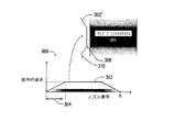
図3は、典型的なランププリントマスク技術を示す。折れ線グラフ300に示すように、ランププリントマスク関数302を、ペン114のノズル118に有効に適用することができる。y軸は、各(番号が付された)ノズル118に適用される使用の確率を表す。x軸は、ノズル118を番号で表す。ここで、ノズルは、0からKに番号付けされている。ある実施形態では、たとえば、使用の確率は、端部ノズル118a近くでは低いパーセンテージから高いパーセンテージへ(たとえば、約0%から約100%へ)一定比率で上昇し、その後、端部ノズル118cに対し、高いパーセンテージから低いパーセンテージへ(たとえば、約100%から約0%へ)一定比率で下降する。上昇ランプと下降ランプとにおけるノズルの数は、たとえば、プリントされているスワスの高さに基づいて確立されてよい。なお、実施形態によっては、ペンの端部のうちの一方の近くのノズル118のみが下降してよい。
【0024】
また、図3には、ランププリントマスク関数302を適用してプリントされたランププリントマスクスワス306の例示的な表現も示す。ランププリントマスク関数302により、有効に、あっても非常にわずかなインク(使用の確率は約0%)がポイント310近くのノズル(複数可)によって塗布され、ずっと多くのインクがポイント308近くのノズル(複数可)によって塗布される(使用の確率は約100%)。
【0025】
この典型的なランピングの技術の1つの問題は、各スワスの領域に、R2LよりL2Rの方がより有効にプリントされるものがある一方で、L2RよりR2Lの方がより有効にプリントされるものもあることである。ランププリントマスク関数302によって定義されるように、ノズル118の使用に変化があるため、結果としての色に、プリント媒体を進むと視覚的に顕著な色の波がある可能性がある。このため、スワスのうちのいくつかが非常に黄色がかるのではなく、たとえば、灰色のスワス内に変化があることになる。
【0026】
厳密に検査すると、ランププリントマスクを使用してプリントされた各スワスに亙って、上部近くがより黄色がかって見える波があることになる。このため、スワス内においてその上部から底部に色または色相シフトがある可能性がある。
【0027】
スワス内のかかる波状の色を低減または除去する解決法を、改良された方法および装置の形態で本明細書において提供する。これら方法および装置により、有利に、望ましくない色相シフトの効果が副次的効果として発生することなく、改良されたドット配置を促進しかつ/またはバンディングを制御しかつ/またはバンディングエラーを制御するのにランププリントマスクおよび他の同様の技術を使用することができる。
【0028】
インク付着の順序に関わる色相シフト効果はしばしば顕著であるが、人間の視覚は、暗インク色(たとえば、C、M、K)よりイエロードット配置における位置決めエラーを感知し難い傾向がある。したがって、他の色にはまだランププリントマスクを適用してよいが、Yインクは、ランププリントマスクを使用せずに付着させることができることが分かった。
【0029】
このため、本発明のある態様によれば、Yインク等の明色インクは、ランププリントマスクを適用することなくプリントされ、一方でCインク、Mインク、Kインクおよび/または他の暗色インクは、ランププリントマスクを使用してプリントされてよい。その結果、ランププリントマスクに起因する明るいインク滴付着の差および/またはスワスにおいて(明るい)インクが最初に(先に)プリントされるか最後に(後に)プリントされるかによる色の変化からもたらされる色の波が、低減または除去される。
【0030】
かかる技術を、図4に例示的に示す。図4では、Yインクに対して非ランプ(non-ramped)プリントマスク400が適用される(または同様に、非確率的プリントマスクが適用される)。例示的な代表的なスワスを、折れ線グラフの上に示す。ここで、Yインク402の非ランプ(non-ramp)プリントマスクスワスは、ノズルのすべてが、スワスの実質的に一様な陰影(すべて暗)によって示されるように、略同じ使用の確率を有することを示す。Bインク(404)、Cインク(406)およびMインク(408)に対する、代表的な確率的ランププリントマスクスワスもまた示す。図3のスワス306と同様に、スワス404、406および408は、ノズルのいくつかが、各スワス内の非均一(勾配)の陰影によって示すように異なる使用の確率を有することを示す。なお、ランププリントマスク関数は、各色のインクに対して異なってよい。
【0031】
したがって、本発明のある実施形態によって、ロジック108は、非ランプの実質的に均一なプリントマスク関数400をYインクペン制御信号に適用するように機能的に構成されてよい。他の実施形態では、確率的プリントマスク関数をYインクペン制御信号にまったく適用しないことによっても同じ結果が達成されてよい。そして、残りのインクペンにおいて、それらの制御信号に確率的または他の同様のランププリント関数を適用して、顕著なバンドおよび/または他のプリントエラーの可能性を低減する助けとすることができる。明色Yインクが結果としてのイメージにおいて顕著でなくなる傾向にあるため、Yインクに非均一ランププリントマスクを適用しないことによってもたらされる他のいかなる潜在的なエラーも、結果としてのプリントを望ましくないほどに劣化させることがない。
【0032】
本発明の様々な方法および装置のいくつかの好ましい実施形態を、添付の図面において示し上記詳細な説明において説明したが、本発明は、開示した例示的な実施形態に限定されず、特許請求の範囲によって示し画定されるような本発明の趣旨から逸脱することなく多数の再構成、変更および代替が可能であることが理解されよう。
【図面の簡単な説明】
【図1】本発明のいくつかの例示的な実施形態による、最終プリントイメージに望ましくないバンディングをもたらす傾向のある色相シフトまたは他の同様の変化を低減または除去するように有利に構成されたカラープリント機器を有する、プリント環境を示すブロック図である。
【図2】反対方向にプリントされた2つの中間色スワスの目に見える差異を例示的に示す図である。
【図3】例示的なランププリントマスク関数を示す折れ線グラフと対応する例証的なスワスとを含む。
【図4】本発明のいくつかの例示的な実施形態による、イエロー(Y)インクに適用される非ランププリントマスク関数を示す折れ線グラフと、Yインクの対応する例証的なスワスと、例証的なランププリントマスク関数に基づくブラック(B)インク、シアン(C)およびマゼンタ(M)のスワスと、を含む。[0001]
BACKGROUND OF THE INVENTION
The present invention relates to an improved method and apparatus that significantly reduces or eliminates visible hue shift banding in bidirectional color printing equipment.
[0002]
[Prior art]
For example, color printing devices such as ink jet printers operate by applying small drops of ink to a print medium (eg, paper), thereby forming dots. By combining dots colored with different colors, various desired colors are formed. As an example, some inkjet printers utilize four different colors, cyan, magenta, yellow and black ink. These inks are generally supplied by an ink printhead having a number of nozzles that can be selectively controlled to eject ink droplets onto the print media. The printhead is typically located in a printhead carriage that is movably controlled by a transport mechanism, thereby selectively controlling the ink printhead that is moving relative to the print media, thereby providing a swath of colors. Can be applied to a portion of the print medium.
[0003]
Some printing devices are configured to print bidirectionally. This means, for example, that swaths can be printed when the carriage moves the print medium from the right side to the left side and then returns the paper from the left side to the right side. This bi-directional movement is then continued down the print medium as needed to print the desired content.
[0004]
[Problems to be solved by the invention]
In order to reduce the visibility of some print errors in the resulting print, the printing device can use the nozzles in the printhead by applying a probability or other similar function selected in the print logic. There is something to control. Such probability functions generally print less ink from nozzles near the end of the printhead. However, it has been found that with these printing devices, for some colors, swath bidirectional printing can cause other print errors, such as wavy color changes. These changes create undesirable hue shifts that can result in visually noticeable bands in the resulting print.
[0005]
Accordingly, there is a need for an improved method and apparatus that significantly reduces or eliminates visible hue shift banding in bidirectional color printing equipment.
[0006]
[Means for Solving the Problems]
In accordance with some aspects of the present invention, improved methods and apparatus are provided that significantly reduce or eliminate visible hue shift banding and / or other similar defects introduced in bidirectional color printing. The
[0007]
The aforementioned needs and other needs are met, for example, by methods used in printing color swaths in bi-directional printing equipment. The bidirectional printing device is configured to use a plurality of color inks including at least one light color ink and at least one dark color ink. The method includes selectively printing at least one dark ink on a print medium based on a non-uniform print mask function. The method further includes selectively printing at least one light ink on the print medium based on the substantially uniform print mask function.
[0008]
According to still another embodiment of the present invention, a printing apparatus capable of printing a color swath bidirectionally is provided. Here, the printing apparatus includes a printing mechanism controlled by logic. The printing mechanism can be configured to selectively print color swaths on a print medium using a plurality of color inks including at least one light color ink and at least one dark color ink. Logic causes the print mechanism to selectively print dark ink on the print media in a non-uniform stochastic manner and selectively print light ink on the print media in a substantially uniform stochastic manner. Configured to be operable.
[0009]
The various methods and apparatus of the present invention can be more fully understood by reference to the following detailed description in conjunction with the accompanying drawings.
[0010]
DETAILED DESCRIPTION OF THE INVENTION
FIG. 1 illustrates an
[0011]
As described in the exemplary embodiment below, the
[0012]
The
[0013]
The print head carriage 112 has at least one
[0014]
Since this exemplary embodiment is an inkjet printer, the
[0015]
In this embodiment, the
[0016]
Since these and other print engines, printheads, and print processes / mechanisms and techniques are well known, the remaining description focuses on some problems detected in the bi-directional print process and is an improvement that addresses such problems. A description of the method and apparatus provided is provided.
[0017]
It has been found that the order in which the various inks are applied to the print media 120 affects the particular final resulting color. This is particularly noticeable in regions with intermediate colors (eg, gray and other colors where human vision is particularly sensitive to subtle color changes). For example, if C ink is applied before M ink, the resulting color may be different than if M ink is applied before C ink. As described below, one particular problem is caused by the order in which Y ink is applied during bidirectional printing.
[0018]
Since the
[0019]
As a result of this type of ink application sequence and other similar sequences, it has been found that when printing a neutral color, the first swath 202 tends to appear more yellow than the second swath 204. One possible reason for this is that an ink drop placed on a blank or
[0020]
As mentioned above, such hue changes in the resulting image are often visible. This is especially true when the region of the same color over multiple adjacent swaths is wider, where the L2R swath has a different color than the R2L swath.
[0021]
Some of this banding can be reduced by multi-pass printing, in which case such a color change is generally obscured because a given region performs generally equal amounts of L2R and R2L printing. Unfortunately, even in multi-pass printing, it has been found that hue shift banding can occur when using a ramp print mask.
[0022]
In order to better understand why such hue shift banding can occur, it is necessary to consider techniques using lamp print masks. A ramp print mask is useful, for example, in reducing other types of banding caused by positioning errors, such as stepping errors, dot placement errors, and the like. Basically, the ramp print mask technique includes not using the top nozzle 118a as much as the
[0023]
FIG. 3 shows a typical lamp print mask technique. As shown in the
[0024]
FIG. 3 also shows an exemplary representation of a ramp
[0025]
One problem with this typical ramping technique is that in each swath area, L2R is printed more effectively than R2L, while R2L is printed more effectively than L2R. There is also. Because there is a change in the use of the
[0026]
Upon close inspection, there will be waves that appear more yellowish near the top over each swath printed using the lamp print mask. For this reason, there may be a color or hue shift from the top to the bottom of the swath.
[0027]
Solutions for reducing or eliminating such wavy colors in the swath are provided herein in the form of improved methods and apparatus. These methods and apparatus advantageously facilitate improved dot placement and / or control banding and / or control banding errors without the undesirable hue shift effect occurring as a side effect. Lamp print masks and other similar techniques can be used.
[0028]
Although the hue shift effect related to the order of ink deposition is often noticeable, human vision tends to be less sensitive to positioning errors in yellow dot placement than dark ink colors (eg, C, M, K). Thus, it has been found that the Y ink can be deposited without the use of a lamp print mask, although lamp print masks may still be applied to other colors.
[0029]
Thus, according to one aspect of the present invention, light inks such as Y ink are printed without applying a lamp print mask, while C ink, M ink, K ink and / or other dark inks are It may be printed using a lamp print mask. The result is a difference in bright ink drop adhesion due to the lamp print mask and / or a change in color depending on whether the (bright) ink is printed first (first) or last (after) in the swath. Color waves that are lost are reduced or eliminated.
[0030]
Such a technique is exemplarily shown in FIG. In FIG. 4, a
[0031]
Thus, in accordance with certain embodiments of the present invention, the
[0032]
While several preferred embodiments of the various methods and apparatus of the present invention have been illustrated in the accompanying drawings and described in the foregoing detailed description, the present invention is not limited to the disclosed exemplary embodiments, but is claimed. It will be appreciated that numerous reconfigurations, modifications and alternatives are possible without departing from the spirit of the invention as shown and defined by the scope.
[Brief description of the drawings]
FIG. 1 is a color advantageously configured to reduce or eliminate hue shifts or other similar changes that tend to result in undesirable banding in the final printed image, according to some exemplary embodiments of the present invention. 1 is a block diagram illustrating a printing environment having a printing device. FIG.
FIG. 2 exemplarily shows a visible difference between two intermediate color swaths printed in opposite directions.
FIG. 3 includes a line graph showing an exemplary ramp print mask function and corresponding exemplary swaths.
FIG. 4 is a line graph showing a non-ramp print mask function applied to yellow (Y) ink, a corresponding exemplary swath of Y ink, and exemplary, according to some exemplary embodiments of the invention Black (B) ink, cyan (C) and magenta (M) swaths based on a simple ramp print mask function.
Claims (8)
色スワスの、少なくとも一つの側方端部の周辺領域に対応するノズルの使用される確率を他のノズルに比べて低くする、非均一なプリントマスク関数に基づいてプリント媒体に前記少なくとも1つの暗色インクを選択的にプリントすること、
全てのノズルの使用される確率を同じにする、均一なプリントマスク関数に基づいて前記プリント媒体に前記少なくとも1つの明色インクを選択的にプリントすること、を含み、前記少なくとも1つの明色インクは、イエローインクを含む方法。A method used in printing a color swath in a bidirectional printing device configured to use a plurality of color inks including at least one light color ink and at least one dark color ink, comprising:
The at least one dark color on the print medium based on a non-uniform print mask function that reduces the probability that a nozzle corresponding to the peripheral region of at least one side edge of the color swath will be used compared to other nozzles Selectively printing ink,
The probability of use of all of the nozzles the same selectively to print, only contains the at least one light color ink on said print medium based on uniform print mask function, wherein the at least one light-colored The method wherein the ink includes yellow ink .
少なくとも1つの明色インクと少なくとも1つの暗色インクとを含む複数のカラーインクを使用して、プリント媒体に色スワスを選択的にプリントするように構成可能なプリント機構と、
該プリント機構に動作的に連結され、該プリント機構に対し、色スワスの、少なくとも一つの側方端部の周辺領域に対応するノズルの使用される確率が他のノズルに比べて低くなるようなやり方で、前記プリント媒体に前記少なくとも1つの暗色インクを選択的にプリントさせ、全てのノズルの使用される確率が同じであるようなやり方で、該プリント媒体に前記少なくとも1つの明色インクを選択的にプリントさせるように構成された、ロジックと、を具備し、前記少なくとも1つの明色インクは、イエローインクを含むプリント装置。A printing apparatus capable of printing color swaths in both directions,
A print mechanism configurable to selectively print color swaths on a print medium using a plurality of color inks including at least one light color ink and at least one dark color ink;
Operatively connected to the printing mechanism, such that the probability of using a nozzle corresponding to the peripheral region of at least one lateral end of the color swath is lower than that of the other nozzles. In a manner, the print medium is selectively printed with the at least one dark ink, and the at least one light color ink is selected on the print medium in a manner such that all nozzles have the same probability of being used. And a logic configured to cause printing to be performed , wherein the at least one light ink includes a yellow ink .
スワスのプリント中に、少なくとも1つの明色インクプリントヘッドのすべてのノズルから実質的に等しい数の液滴の付着を可能にすること、
前記スワスの前記プリント中に、少なくとも1つの暗色インクプリントヘッドの、前記スワスの側方端部の周辺領域に対応するノズルに対する相対的に少ない液滴と、前記スワスの中央部の周辺領域に対応するノズルからの相対的に多い液滴との付着を可能にすること、を含み、前記少なくとも1つの明色インクプリントヘッドは、イエローインクプリントヘッドを備える、方法。A method of printing an image swath with a bi-directional printer having print heads for each color, each print head having a logical linear arrangement of nozzles,
Enabling the deposition of substantially equal numbers of droplets from all nozzles of at least one light ink printhead during swath printing;
During the printing of the swath, at least one dark ink printhead corresponds to a relatively small number of droplets relative to the nozzle corresponding to the peripheral area of the lateral end of the swath and the peripheral area of the central portion of the swath. allowing the attachment of relatively large droplets from nozzles, only it contains the at least one light color ink printhead includes a yellow ink printhead, the method.
色スワスの、少なくとも一つの側方端部の周辺領域に対応するノズルの使用される確率を他のノズルに比べて低くする、非均一なプリントマスク関数に基づいてプリント媒体に前記少なくとも1つの暗色インクを選択的にプリントする手段と、
全てのノズルの使用される確率を同じにする、実質的に均一なプリントマスク関数に基づいて前記プリント媒体に前記少なくとも1つの明色インクを選択的にプリントする手段と、を具備し、前記少なくとも1つの明色インクは、イエローインクを含む装置。An apparatus used in printing a color swath in a bi-directional printing device configured to use a plurality of color inks including at least one light color ink and at least one dark color ink,
The at least one dark color on the print medium based on a non-uniform print mask function that reduces the probability that a nozzle corresponding to the peripheral region of at least one side edge of the color swath will be used compared to other nozzles Means for selectively printing ink;
Means for selectively printing the at least one light color ink on the print medium based on a substantially uniform print mask function that makes all nozzles have the same probability of being used , One bright ink includes a yellow ink .
スワスのプリント中に、少なくとも1つの明色インクプリントヘッドのすべてのノズルから実質的に等しい数の液滴の付着を可能にする手段と、
前記スワスの前記プリント中に、少なくとも1つの暗色インクプリントヘッドの、前記スワスの側方端部の周辺領域に対応するノズルに対する相対的に少ない液滴と、前記スワスの中央部の周辺領域に対応するノズルからの相対的に多い液滴との付着を可能にする手段と、を具備し、前記少なくとも1つの明色インクプリントヘッドは、イエローインクプリントヘッドを備える、装置。An apparatus for printing image swaths with a bi-directional printer having printheads for each color, each printhead having a logical linear arrangement of nozzles,
Means for allowing the deposition of a substantially equal number of droplets from all nozzles of at least one light ink printhead during swath printing;
During the printing of the swath, at least one dark ink printhead corresponds to a relatively small number of droplets relative to the nozzle corresponding to the peripheral area of the lateral end of the swath and the peripheral area of the central portion of the swath. Means for allowing attachment of relatively many droplets from nozzles , wherein the at least one light ink printhead comprises a yellow ink printhead .
Applications Claiming Priority (2)
| Application Number | Priority Date | Filing Date | Title |
|---|---|---|---|
| US10/060,619 US6491374B1 (en) | 2002-01-30 | 2002-01-30 | Methods and apparatuses for printing with uniform and non-uniform print mask functions |
| US10/060,619 | 2002-01-30 |
Publications (2)
| Publication Number | Publication Date |
|---|---|
| JP2003226004A JP2003226004A (en) | 2003-08-12 |
| JP3896329B2 true JP3896329B2 (en) | 2007-03-22 |
Family
ID=22030661
Family Applications (1)
| Application Number | Title | Priority Date | Filing Date |
|---|---|---|---|
| JP2002366820A Expired - Fee Related JP3896329B2 (en) | 2002-01-30 | 2002-12-18 | Method and apparatus for printing with uniform and non-uniform print mask functions |
Country Status (4)
| Country | Link |
|---|---|
| US (1) | US6491374B1 (en) |
| EP (1) | EP1332887B1 (en) |
| JP (1) | JP3896329B2 (en) |
| DE (1) | DE60300893T2 (en) |
Cited By (1)
| Publication number | Priority date | Publication date | Assignee | Title |
|---|---|---|---|---|
| JP2011189729A (en) * | 2010-02-19 | 2011-09-29 | Seiko I Infotech Inc | Recording apparatus and recording method |
Families Citing this family (9)
| Publication number | Priority date | Publication date | Assignee | Title |
|---|---|---|---|---|
| US20040190786A1 (en) * | 2003-03-24 | 2004-09-30 | Khageshwar Thakur | Method of image enhancement for an imaging apparatus |
| US6866365B1 (en) | 2004-04-01 | 2005-03-15 | Eastman Kodak Company | Bi-directional color printer and method of printing |
| US7472983B2 (en) * | 2005-01-04 | 2009-01-06 | Eastman Kodak Company | Intelligent print mask |
| WO2013187909A1 (en) * | 2012-06-15 | 2013-12-19 | Hewlett-Packard Development Company, L.P. | Color-directional printing |
| US8905521B2 (en) * | 2013-01-30 | 2014-12-09 | Hewlett-Packard Development Company, L.P. | Printing method and apparatus |
| WO2016015766A1 (en) * | 2014-07-31 | 2016-02-04 | Hewlett-Packard Development Company, L.P. | A method of printing and printer |
| EP3212423B1 (en) | 2014-10-31 | 2020-08-05 | Hewlett-Packard Development Company, L.P. | Method of printing in a multipass mode and a printing apparatus for implementing such a method |
| JP6488803B2 (en) * | 2015-03-23 | 2019-03-27 | セイコーエプソン株式会社 | Droplet ejection apparatus, mask pattern, and droplet ejection method |
| US9834017B2 (en) * | 2015-11-20 | 2017-12-05 | Funai Electric Co. Ltd. | Inkjet printer |
Family Cites Families (5)
| Publication number | Priority date | Publication date | Assignee | Title |
|---|---|---|---|---|
| JP2891799B2 (en) * | 1991-06-07 | 1999-05-17 | キヤノン株式会社 | Inkjet recording method |
| US6273549B1 (en) * | 1998-08-13 | 2001-08-14 | Hewlett-Packard Company | Multiple pass color shift correction technique for an inkjet printer |
| US6965452B2 (en) * | 1998-09-09 | 2005-11-15 | Hewlett-Packard Development Company, L.P. | Masks on demand for use in incremental printing |
| US6254217B1 (en) * | 1999-07-29 | 2001-07-03 | Hewlett-Packard Company | Apparatus and method for hue shift compensation in a bidirectional printer |
| US6310640B1 (en) * | 1999-09-20 | 2001-10-30 | Hewlett-Packard Company | Banding reduction in multipass printmodes |
-
2002
- 2002-01-30 US US10/060,619 patent/US6491374B1/en not_active Expired - Lifetime
- 2002-12-18 JP JP2002366820A patent/JP3896329B2/en not_active Expired - Fee Related
-
2003
- 2003-01-15 EP EP03250238A patent/EP1332887B1/en not_active Expired - Fee Related
- 2003-01-15 DE DE60300893T patent/DE60300893T2/en not_active Expired - Lifetime
Cited By (1)
| Publication number | Priority date | Publication date | Assignee | Title |
|---|---|---|---|---|
| JP2011189729A (en) * | 2010-02-19 | 2011-09-29 | Seiko I Infotech Inc | Recording apparatus and recording method |
Also Published As
| Publication number | Publication date |
|---|---|
| US6491374B1 (en) | 2002-12-10 |
| EP1332887A2 (en) | 2003-08-06 |
| EP1332887B1 (en) | 2005-06-29 |
| JP2003226004A (en) | 2003-08-12 |
| DE60300893T2 (en) | 2006-05-11 |
| EP1332887A3 (en) | 2003-10-29 |
| DE60300893D1 (en) | 2005-08-04 |
Similar Documents
| Publication | Publication Date | Title |
|---|---|---|
| EP1582358B1 (en) | Formation of images | |
| EP1273453B1 (en) | Print direction dependent color conversion in bidirectional printing | |
| US7484821B2 (en) | Method of determining ink ejection method, printing apparatus, and method of manufacturing printing apparatus | |
| US8939535B2 (en) | Defective printer nozzle compensation control | |
| JP3896329B2 (en) | Method and apparatus for printing with uniform and non-uniform print mask functions | |
| US6659582B2 (en) | Apparatus and method for fortification of black pigment based ink using black dye based ink | |
| JP2000118013A (en) | Method for correcting multiple pass color shift for ink- jet printer | |
| US8550587B2 (en) | Liquid ejecting apparatus and liquid ejecting method | |
| JP3996857B2 (en) | Inkjet printer and inkjet printing system | |
| US8529004B2 (en) | Printing apparatus and printing method | |
| US7481516B2 (en) | Inkjet recording apparatus and inkjet recording method | |
| US10166760B2 (en) | Droplet ejection control apparatus, droplet ejection control method, and droplet ejection apparatus | |
| JP3937112B2 (en) | Image forming method, image forming control apparatus, and image forming apparatus | |
| EP1676710B1 (en) | Printing device and control method thereof | |
| US8926040B2 (en) | Printing device and printing method | |
| JP6673438B2 (en) | Inkjet printer | |
| US10124591B2 (en) | Printer and head unit | |
| US6561609B2 (en) | Multiple drop weight printing system | |
| JP2015205431A (en) | Recording device, control method thereof, and computer program | |
| JP7391575B2 (en) | Recording device and recording method | |
| EP0827837A2 (en) | Method of inhibiting a print artifact associated with a printer pause | |
| JP6705466B2 (en) | Liquid ejecting apparatus, liquid ejecting method, and printing program | |
| JP2009226640A (en) | Method for acquiring correction value and liquid jet device | |
| JP3472823B2 (en) | Method of interlaced printing using inkjet printer | |
| JP2023072641A (en) | Recording apparatus and recording method |
Legal Events
| Date | Code | Title | Description |
|---|---|---|---|
| A131 | Notification of reasons for refusal |
Free format text: JAPANESE INTERMEDIATE CODE: A131 Effective date: 20060117 |
|
| A601 | Written request for extension of time |
Free format text: JAPANESE INTERMEDIATE CODE: A601 Effective date: 20060411 |
|
| A602 | Written permission of extension of time |
Free format text: JAPANESE INTERMEDIATE CODE: A602 Effective date: 20060417 |
|
| A521 | Request for written amendment filed |
Free format text: JAPANESE INTERMEDIATE CODE: A523 Effective date: 20060713 |
|
| A131 | Notification of reasons for refusal |
Free format text: JAPANESE INTERMEDIATE CODE: A131 Effective date: 20060808 |
|
| A521 | Request for written amendment filed |
Free format text: JAPANESE INTERMEDIATE CODE: A523 Effective date: 20061101 |
|
| TRDD | Decision of grant or rejection written | ||
| A01 | Written decision to grant a patent or to grant a registration (utility model) |
Free format text: JAPANESE INTERMEDIATE CODE: A01 Effective date: 20061212 |
|
| A61 | First payment of annual fees (during grant procedure) |
Free format text: JAPANESE INTERMEDIATE CODE: A61 Effective date: 20061218 |
|
| R150 | Certificate of patent or registration of utility model |
Free format text: JAPANESE INTERMEDIATE CODE: R150 Ref document number: 3896329 Country of ref document: JP Free format text: JAPANESE INTERMEDIATE CODE: R150 |
|
| FPAY | Renewal fee payment (event date is renewal date of database) |
Free format text: PAYMENT UNTIL: 20091222 Year of fee payment: 3 |
|
| FPAY | Renewal fee payment (event date is renewal date of database) |
Free format text: PAYMENT UNTIL: 20101222 Year of fee payment: 4 |
|
| R250 | Receipt of annual fees |
Free format text: JAPANESE INTERMEDIATE CODE: R250 |
|
| FPAY | Renewal fee payment (event date is renewal date of database) |
Free format text: PAYMENT UNTIL: 20111222 Year of fee payment: 5 |
|
| R250 | Receipt of annual fees |
Free format text: JAPANESE INTERMEDIATE CODE: R250 |
|
| FPAY | Renewal fee payment (event date is renewal date of database) |
Free format text: PAYMENT UNTIL: 20121222 Year of fee payment: 6 |
|
| R250 | Receipt of annual fees |
Free format text: JAPANESE INTERMEDIATE CODE: R250 |
|
| FPAY | Renewal fee payment (event date is renewal date of database) |
Free format text: PAYMENT UNTIL: 20121222 Year of fee payment: 6 |
|
| S111 | Request for change of ownership or part of ownership |
Free format text: JAPANESE INTERMEDIATE CODE: R313113 |
|
| FPAY | Renewal fee payment (event date is renewal date of database) |
Free format text: PAYMENT UNTIL: 20121222 Year of fee payment: 6 |
|
| R360 | Written notification for declining of transfer of rights |
Free format text: JAPANESE INTERMEDIATE CODE: R360 |
|
| R360 | Written notification for declining of transfer of rights |
Free format text: JAPANESE INTERMEDIATE CODE: R360 |
|
| R371 | Transfer withdrawn |
Free format text: JAPANESE INTERMEDIATE CODE: R371 |
|
| FPAY | Renewal fee payment (event date is renewal date of database) |
Free format text: PAYMENT UNTIL: 20121222 Year of fee payment: 6 |
|
| S111 | Request for change of ownership or part of ownership |
Free format text: JAPANESE INTERMEDIATE CODE: R313113 |
|
| FPAY | Renewal fee payment (event date is renewal date of database) |
Free format text: PAYMENT UNTIL: 20121222 Year of fee payment: 6 |
|
| R350 | Written notification of registration of transfer |
Free format text: JAPANESE INTERMEDIATE CODE: R350 |
|
| FPAY | Renewal fee payment (event date is renewal date of database) |
Free format text: PAYMENT UNTIL: 20121222 Year of fee payment: 6 |
|
| FPAY | Renewal fee payment (event date is renewal date of database) |
Free format text: PAYMENT UNTIL: 20131222 Year of fee payment: 7 |
|
| R250 | Receipt of annual fees |
Free format text: JAPANESE INTERMEDIATE CODE: R250 |
|
| R250 | Receipt of annual fees |
Free format text: JAPANESE INTERMEDIATE CODE: R250 |
|
| R250 | Receipt of annual fees |
Free format text: JAPANESE INTERMEDIATE CODE: R250 |
|
| R250 | Receipt of annual fees |
Free format text: JAPANESE INTERMEDIATE CODE: R250 |
|
| R250 | Receipt of annual fees |
Free format text: JAPANESE INTERMEDIATE CODE: R250 |
|
| R250 | Receipt of annual fees |
Free format text: JAPANESE INTERMEDIATE CODE: R250 |
|
| R250 | Receipt of annual fees |
Free format text: JAPANESE INTERMEDIATE CODE: R250 |
|
| LAPS | Cancellation because of no payment of annual fees |