JP3892529B2 - Device for adjusting the contrast of video images - Google Patents
Device for adjusting the contrast of video images Download PDFInfo
- Publication number
- JP3892529B2 JP3892529B2 JP13843197A JP13843197A JP3892529B2 JP 3892529 B2 JP3892529 B2 JP 3892529B2 JP 13843197 A JP13843197 A JP 13843197A JP 13843197 A JP13843197 A JP 13843197A JP 3892529 B2 JP3892529 B2 JP 3892529B2
- Authority
- JP
- Japan
- Prior art keywords
- input
- output
- value
- color difference
- red
- Prior art date
- Legal status (The legal status is an assumption and is not a legal conclusion. Google has not performed a legal analysis and makes no representation as to the accuracy of the status listed.)
- Expired - Fee Related
Links
Images

Classifications
-
- H—ELECTRICITY
- H04—ELECTRIC COMMUNICATION TECHNIQUE
- H04N—PICTORIAL COMMUNICATION, e.g. TELEVISION
- H04N5/00—Details of television systems
- H04N5/44—Receiver circuitry for the reception of television signals according to analogue transmission standards
- H04N5/57—Control of contrast or brightness
-
- H—ELECTRICITY
- H04—ELECTRIC COMMUNICATION TECHNIQUE
- H04N—PICTORIAL COMMUNICATION, e.g. TELEVISION
- H04N9/00—Details of colour television systems
- H04N9/64—Circuits for processing colour signals
- H04N9/68—Circuits for processing colour signals for controlling the amplitude of colour signals, e.g. automatic chroma control circuits
Description
【0001】
【発明の属する技術分野】
本発明はビデオ画像のコントラストレベルが調整されることを可能とする装置に関する。
【0002】
【従来の技術】
当業者に知られているように、高いコントラストを持つビデオ画像領域は、それが構成される細部描写とそれを取り囲む細部描写の両方がはっきりと見えることを妨げる。そのとき細部を再現させるためには、コントラストレベルを低下させる必要がある。
【0003】
例えば、テレビ画面上でビデオ画像を表示する場合、観察者はコントラストレベルの調節を利用できる。画像の一若しくはそれ以上の領域が、画像の残りの部分に比べて高すぎるコントラストを持つ場合、観察者はコントラストを低下させるようにコントラスト制御を作用させることができる。
【0004】
【発明が解決しようとする課題】
コントラスト制御は、輝度信号(Y)のレベル、青色差クロミナンス信号(CB)及び赤色差クロミナンス信号(CR)を同時に調節できる回路に作用する調節パラメータを適用される。使用者の調節制御の同時適用の結果、画像の最も暗い領域はその後もはや十分なコントラストを持たなくなる。これらの最も暗い領域が構成される細部描写はもはや識別できないものとなる。
【0005】
本発明はこれらの欠点を有しない。
【0006】
【課題を解決するための手段】
本発明はビデオ画像の輝度信号及び青色差クロミナンス信号及び赤色差クロミナンス信号を赤色、緑色及び青色の色信号に変換することを可能にする装置に関する。該装置は、変換マトリックスと、輝度信号及び青色差クロミナンス信号及び赤色差クロミナンス信号の振幅が使用者調節パラメータにより変更されるのを可能とする手段とからなる。該装置は該色信号が飽和値に達するときに該変換マトリックスの出力での最高値を有する該色信号が白レベルのx%に等しい飽和値を超えることを防止する付加的な手段を具備する。
【0007】
本発明の好ましい実施例によれば、変換マトリックスの出力での最高値を持つ色情報は白レベル値の70%を超え得ない。
しかし、他の値は別の実施例に従い可能である。
本発明によれば、好ましいことに、輝度又は赤若しくは青色差の信号の高い値に対してコントラストに限定を設けることは、使用者に対して定常的なコントラスト調節を強いることの回避を可能にする。
【0008】
【発明の実施の形態】
本発明の他の特徴と利点は、ここに添付された図面と共に説明される好ましい実施例により明らかとなろう。
図1は本発明にかかる調整装置の第一実施例を表し;
図2は本発明にかかる調整装置の第二実施例を表し;
図3は従来技術にかかる装置及び本発明にかかる装置の応答曲線を表す。
【0009】
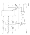
全ての図面中で、同一の参照記号は同一の構成要素を表す。
図1は本発明にかかる調整装置の第一実施例を表す。本発明によれば、調整装置は、機能がY,CB,CR成分をR,G,B成分に変換することであるマトリックス7から来る色情報項目R,G,Bの中の一つにより推定される最大値の検出に基づく輝度成分Y並びに青色CB及び赤色CR色差クロミナンス成分のレベルを調節することを可能にする。
【0010】
以下M(R,G,B)と記される、R,G,Bの最大値は符号8で示される3つの入力と一つの出力を有するOR機能を用いて検出される。この目的のため、R,G,B色情報項目のそれぞれはOR機能の異なる入力に適用される。OR機能8は公知の手段により構成される。例えば、それは三つのダイオードを使用して構成された回路である。
【0011】
OR機能の出力は比較器9の第一の入力に接続される。そのため値M(R,G,B)は比較器9の第一の入力に印加され、第二の入力は掛算器10から電圧VT2を受ける。電圧VT2は電圧VT1のk倍に等しく、ここで、kは使用者のコントラスト調節のパラメータであり、VT1はその値が工場で望みのように設定される基準電圧である。本発明によれば、kは好ましくは0.25と1との間である。
【0012】
比較器9の出力信号における偏差値は、ダイオードDを介して積分コンデンサCの端子に印加される。抵抗器Aは、コンデンサCの放電を可能とするように、コンデンサCと並列に設けられる。CとAの値は、コンデンサCの端子での電圧Sが少なくとも一のビデオ画像フレームの期間中実質的に一定であるように選択される。限定はしないが例として、コンデンサCは500nFの値を有し、抵抗器Aは680キロオームの値を有する。
【0013】
積分コンデンサCの端子に受けれる出力電圧Sは、調整係数ksを生成するために電圧/係数変換回路11に印加される。電圧/係数変換回路11はそれ自体知られた方法により製造される。そのため、ここではその説明を省略する。
調整係数ksは、三つの夫々の掛算器1,2及び3からの信号k×Y,k×CB及びk×CRを夫々の入力に受ける三つの掛算器4,5,6の三つ制御入力に同時に印加される。ここでkは上記の使用者のコントラスト調節パラメータである。従って、変換マトリックスの入力に印加された輝度、青色差及び赤色差信号はそれぞれ、
ks×k×Y;ks×k×CB及びks×k×CR:に等しくなる。
【0014】
本発明によれば、係数ksは好ましくは0.5と1との間の値を有する。
好ましくは、調整操作は三つの信号R,G又はBのうちの何れか一つを基にして行なわれる。
図2は本発明による調整装置の第二実施例を示す。
この第二実施例によれば、基準電圧VT1は比較器の第二の入力に直接に接続され、そしてOR機能8の出力は、分割器12の入力に接続され、分割器の出力は比較器の第一の入力に接続されている。分割器12は使用者のコントラスト調節のパラメータkにより制御される。従って、分割器12の出力電圧は量kにより分割された分割器12の入力電圧に等しい。
【0015】
図2の回路の他の全ての構成要素は、図1中で記載したものと同一である。従って、図2中で記載された回路の動作は図1で記載したものと原理的に同じである。しかし、製造に関して、図1に記載された回路は分割器を必要としないという利点を有する。図1に記載された回路によれば、使用者調節係数kは四つの掛算器1,2,3及び10に印加される。回路を複雑にすることを避けるため、これら四つの掛算器は全く同一であることが望ましい。好ましくは、一方で信号Y,CB,CRに対する、及び他方で信号M(R,G,B)に対するkの作用はこうして最適条件下で整合される。
【0016】
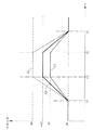
図3は従来技術による装置及び本発明による装置の応答曲線を表す。
図3は3本の曲線、C1,C2及びC3からなる。曲線C1とC2は従来技術による応答曲線である。
曲線C1は、コントラストレベルの調節の無いときの量M(R,G,B)の飽和現象を示す。
【0017】
時間の経過に伴う曲線C1中の変化によって示されるコントラストの変化はビデオ画像の受像の例に対応する。ビデオ画像の受像の他の例に対応して、コントラストの変化の他のタイプが可能であることは明白である。曲線C1によって示される例によれば、量M(R,G,B)は、時間t1での黒レベルVBから時間t2での白レベルVWへ移行し、時間t2とt3の間の白レベルにとどまり時間t3での白レベルVWから時間t4での黒レベルへ移行する。
【0018】
曲線C2は、例として、黒レベルVBと使用者により固定された飽和レベルVSとの間の量M(R,G,B)に対する飽和曲線を示す。
時間の経過に伴う曲線C2中の変化によって示されるコントラストの変化は、曲線C1に対するものと同一のビデオ画像の受像の条件に対応する。
飽和レベルVSは調整パラメータkにより使用者によって調節される。画像が高いコントラストの領域を有する場合、使用者はコントラストをかなり減少させざるを得ない。従って、レベルVSは量M(R,G,B)を大きく減少させるレベルである。画像がもはやこのような高いコントラストの領域を有しないときは、コントラストを回復するために使用者はその後再びその調節の修正を強いられる。そのコントラストが大きく変化する画像に対しては、使用者は非常に多くの回数コントラストを修正する必要がある。
【0019】
本発明による曲線C3は、例として黒レベルVBと飽和レベルVT2との間の量M(R,G,B)に対する飽和曲線を示す。
時間の経過に伴う曲線C3の変化によって示されるコントラストの変化は、例として、曲線C1とC2に対応するものと同一のビデオ画像の受像の条件に対応する。
【0020】
使用者による如何なる調節も、量M(R,G,B)は白レベルVWの値には到達しない。好ましくは、本発明による装置は、白レベルになることを防ぐために実行される量M(R,G,B)の自動飽和のための、図1又は2に記載されたような手段からなる。この自動飽和値はVT2に等しい。前に記載されたように、VT2の値は白レベルVWの70%に相当する。本発明の装置によれば好ましくは、使用者にとって、そのコントラスト変化が目に不愉快ではない画像を得るために、従来技術による場合と同様の多くの回数の調節を行なう必要は無い。
【0021】
上記の記載は、多様な色情報項目R,G,Bからなるカラービデオ画像の例を用いてなされた。当業者にとって、本発明を黒−白の画像及びもはやカラー画像でないものの処理に適用する場合に、”色情報”の語句を”輝度情報”の語句に置き換えればよいことは明らかである。
【0022】
【発明の効果】
本発明によれば、輝度又は赤若しくは青色差の信号の高い値に対してコントラストに限定を設け、使用者に対して定常的なコントラスト調節を強いることの回避を可能にする。
【図面の簡単な説明】
【図1】本発明にかかる調整装置の第一実施例を表す。
【図2】本発明にかかる調整装置の第二実施例を表す。
【図3】従来技術にかかる装置及び本発明にかかる装置の応答曲線を表す。
【符号の説明】
1,2,3,4,5,6,10 掛算器
7 変換マトリックス
8 OR機能
9 比較器
11 電圧/係数変換回路
12 分割器
Y 輝度信号
CB 青色差クロミナンス信号
CR 赤色差クロミナンス信号
k 使用者調節パラメータ
ks 調整係数
C コンデンサ
A 抵抗器
S 電圧
D ダイオード
R 赤色信号
G 緑色信号
B 青色信号
VW 白レベル
VT1 基準電圧
VT2 飽和値[0001]
BACKGROUND OF THE INVENTION
The present invention relates to a device that allows the contrast level of a video image to be adjusted.
[0002]
[Prior art]
As is known to those skilled in the art, a high contrast video image region prevents both the detailed description of it and the detailed description surrounding it from being clearly visible. At that time, in order to reproduce details, it is necessary to reduce the contrast level.
[0003]
For example, when displaying a video image on a television screen, an observer can utilize adjustment of the contrast level. If one or more regions of the image have a contrast that is too high compared to the rest of the image, the viewer can act on the contrast control to reduce the contrast.
[0004]
[Problems to be solved by the invention]
The contrast control is applied with an adjustment parameter that acts on a circuit that can simultaneously adjust the level of the luminance signal (Y), the blue color difference chrominance signal (CB) and the red color difference chrominance signal (CR). As a result of the simultaneous application of the user's adjustment control, the darkest area of the image no longer has sufficient contrast. The details that make up these darkest areas are no longer distinguishable.
[0005]
The present invention does not have these drawbacks.
[0006]
[Means for Solving the Problems]
The present invention relates to a device which makes it possible to convert a luminance signal of a video image and a blue difference chrominance signal and a red difference chrominance signal into red, green and blue color signals. The apparatus consists of a transformation matrix and means for allowing the amplitudes of the luminance signal, the blue color difference chrominance signal and the red color difference chrominance signal to be changed by a user adjustment parameter. The apparatus comprises additional means for preventing the color signal having the highest value at the output of the transformation matrix from exceeding a saturation value equal to x% of the white level when the color signal reaches a saturation value. .
[0007]
According to a preferred embodiment of the present invention, the color information with the highest value at the output of the transformation matrix cannot exceed 70% of the white level value.
However, other values are possible according to alternative embodiments.
In accordance with the present invention, preferably, limiting the contrast to high values of luminance or red or blue difference signals allows the user to avoid forcing constant contrast adjustment. To do.
[0008]
DETAILED DESCRIPTION OF THE INVENTION
Other features and advantages of the present invention will become apparent from the preferred embodiments described in conjunction with the accompanying drawings.
1 represents a first embodiment of an adjusting device according to the invention;
FIG. 2 shows a second embodiment of the adjusting device according to the invention;
FIG. 3 represents the response curves of the device according to the prior art and the device according to the invention.
[0009]
The same reference symbol represents the same component in all drawings.
FIG. 1 shows a first embodiment of an adjusting device according to the present invention. According to the invention, the adjusting device is estimated by one of the color information items R, G, B coming from the matrix 7 whose function is to convert the Y, CB, CR components into R, G, B components. It is possible to adjust the level of the luminance component Y and the blue CB and red CR chrominance chrominance components based on the detection of the maximum value to be performed.
[0010]
Hereinafter, the maximum values of R, G, and B, denoted as M (R, G, and B), are detected using an OR function having three inputs and one output indicated by
[0011]
The output of the OR function is connected to the first input of the
[0012]
The deviation value in the output signal of the
[0013]
The output voltage S received at the terminal of the integrating capacitor C is applied to the voltage /
The adjustment factor ks is the three control inputs of the three
ks × k × Y; ks × k × CB and ks × k × CR:
[0014]
According to the invention, the coefficient ks preferably has a value between 0.5 and 1.
Preferably, the adjustment operation is performed on the basis of any one of the three signals R, G or B.
FIG. 2 shows a second embodiment of the adjusting device according to the invention.
According to this second embodiment, the reference voltage VT1 is connected directly to the second input of the comparator, and the output of the
[0015]
All other components of the circuit of FIG. 2 are identical to those described in FIG. Therefore, the operation of the circuit described in FIG. 2 is in principle the same as that described in FIG. However, with respect to manufacturing, the circuit described in FIG. 1 has the advantage of not requiring a divider. According to the circuit described in FIG. 1, the user adjustment factor k is applied to the four
[0016]
FIG. 3 represents the response curves of the device according to the prior art and the device according to the invention.
FIG. 3 consists of three curves, C1, C2 and C3. Curves C1 and C2 are response curves according to the prior art.
A curve C1 shows a saturation phenomenon of the amount M (R, G, B) when the contrast level is not adjusted.
[0017]
The change in contrast indicated by the change in curve C1 over time corresponds to an example of receiving a video image. Obviously, other types of contrast changes are possible, corresponding to other examples of receiving video images. According to the example shown by curve C1, the quantity M (R, G, B) transitions from the black level VB at time t1 to the white level VW at time t2 to a white level between times t2 and t3. The transition is made from the white level VW at the time t3 to the black level at the time t4.
[0018]
Curve C2 shows, as an example, a saturation curve for an amount M (R, G, B) between a black level VB and a saturation level VS fixed by the user.
The change in contrast indicated by the change in curve C2 over time corresponds to the same video image reception conditions as for curve C1.
The saturation level VS is adjusted by the user with the adjustment parameter k. If the image has high contrast areas, the user is forced to reduce the contrast considerably. Therefore, the level VS is a level that greatly reduces the amount M (R, G, B). When the image no longer has such a high contrast area, the user is then forced to modify the adjustment again to restore contrast. For an image whose contrast changes greatly, the user needs to correct the contrast very many times.
[0019]
Curve C3 according to the invention shows, for example, a saturation curve for the quantity M (R, G, B) between the black level VB and the saturation level VT2.
The change in contrast indicated by the change in curve C3 over time corresponds, for example, to the same video image reception conditions as those corresponding to curves C1 and C2.
[0020]
In any adjustment by the user, the quantity M (R, G, B) does not reach the value of the white level VW. Preferably, the device according to the invention comprises means as described in FIG. 1 or 2 for the automatic saturation of the quantity M (R, G, B) which is carried out to prevent the white level. This autosaturation value is equal to VT2. As described previously, the value of VT2 corresponds to 70% of the white level VW. The device of the present invention preferably does not require the user to make as many adjustments as in the prior art in order to obtain an image whose contrast change is not unpleasant to the eye.
[0021]
The above description has been made using an example of a color video image composed of various color information items R, G, and B. It will be apparent to those skilled in the art that the term “color information” may be replaced by the term “luminance information” when the present invention is applied to processing black-white images and those that are no longer color images.
[0022]
【The invention's effect】
According to the present invention, the contrast is limited to a high value of the luminance or red or blue difference signal, and it is possible to avoid forcing the user to constantly adjust the contrast.
[Brief description of the drawings]
FIG. 1 shows a first embodiment of an adjusting device according to the present invention.
FIG. 2 shows a second embodiment of the adjusting device according to the present invention.
FIG. 3 represents the response curves of the device according to the prior art and the device according to the invention.
[Explanation of symbols]
1, 2, 3, 4, 5, 6, 10 Multiplier 7
Claims (8)
前記変換する手段によって出力された前記赤色、緑色、及び青色の信号の最高値を検出する手段とを有する、
ビデオ画像のコントラストを調整する装置であって、
使用者調節パラメータに応じて、前記変換手段の入力における前記輝度信号、前記青色差クロミナンス信号、及び前記赤色差クロミナンス信号の振幅を調整する第1の手段と、
前記赤色、緑色、及び青色の信号の前記最高値が白レベルよりも低い飽和値を超えることを防止するため、調整係数に応じて、前記変換手段の入力において、前記輝度信号の、前記青色差クロミナンス信号の、並びに、前記赤色差クロミナンス信号の振幅を調整する第2の手段とを更に有し、
前記調整係数は、前記最高値を検出する手段の出力及び基準電圧に応じて、前記使用者調節パラメータによって制御され、補助アセンブリによって生成されることを特徴とする、装置。 Means for converting the luminance signal of the video image, the blue color difference chrominance signal and red color difference chrominance signals of red, green and blue color signals,
Means for detecting a maximum value of the red, green and blue signals output by the means for converting;
A device for adjusting the contrast of a video image,
First means for adjusting amplitudes of the luminance signal, the blue color difference chrominance signal, and the red color difference chrominance signal at the input of the conversion means according to a user adjustment parameter;
In order to prevent the highest value of the red, green and blue signals from exceeding a saturation value lower than the white level, the blue color difference of the luminance signal at the input of the conversion means according to an adjustment factor. A second means for adjusting a chrominance signal and an amplitude of the red color difference chrominance signal;
The device is characterized in that the adjustment factor is controlled by the user adjustment parameter and generated by an auxiliary assembly in response to the output of the means for detecting the highest value and a reference voltage .
Applications Claiming Priority (2)
| Application Number | Priority Date | Filing Date | Title |
|---|---|---|---|
| FR9607045A FR2749731B1 (en) | 1996-06-07 | 1996-06-07 | DEVICE FOR REGULATING VIDEO IMAGE CONTRAST |
| FR9607045 | 1996-06-07 |
Publications (2)
| Publication Number | Publication Date |
|---|---|
| JPH1065991A JPH1065991A (en) | 1998-03-06 |
| JP3892529B2 true JP3892529B2 (en) | 2007-03-14 |
Family
ID=9492803
Family Applications (1)
| Application Number | Title | Priority Date | Filing Date |
|---|---|---|---|
| JP13843197A Expired - Fee Related JP3892529B2 (en) | 1996-06-07 | 1997-05-28 | Device for adjusting the contrast of video images |
Country Status (6)
| Country | Link |
|---|---|
| US (1) | US5940144A (en) |
| EP (1) | EP0812107B1 (en) |
| JP (1) | JP3892529B2 (en) |
| CN (1) | CN1157945C (en) |
| DE (1) | DE69709576T2 (en) |
| FR (1) | FR2749731B1 (en) |
Families Citing this family (6)
| Publication number | Priority date | Publication date | Assignee | Title |
|---|---|---|---|---|
| JP3494555B2 (en) * | 1997-07-14 | 2004-02-09 | 株式会社日立製作所 | Display device and display method |
| KR100333333B1 (en) * | 1998-12-22 | 2002-06-20 | 윤종용 | Color signal processing device of video signal processing system |
| JP2002077641A (en) * | 2000-08-30 | 2002-03-15 | Matsushita Electric Ind Co Ltd | Facsimile machine |
| EP1380177A1 (en) * | 2001-04-11 | 2004-01-14 | Koninklijke Philips Electronics N.V. | Picture signal contrast control |
| JP2005057621A (en) * | 2003-08-07 | 2005-03-03 | Sanyo Electric Co Ltd | Video signal processing circuit |
| JP4774757B2 (en) * | 2004-09-17 | 2011-09-14 | 株式会社ニコン | Image processing apparatus, image processing program, electronic camera, and image processing method |
Family Cites Families (7)
| Publication number | Priority date | Publication date | Assignee | Title |
|---|---|---|---|---|
| JPH0657066B2 (en) * | 1984-12-20 | 1994-07-27 | キヤノン株式会社 | Color adjustment device |
| JP2515869B2 (en) * | 1988-11-28 | 1996-07-10 | 株式会社日立製作所 | Video signal processing circuit |
| FR2640839B1 (en) * | 1988-12-20 | 1991-03-15 | Portenseigne Radiotechnique | VIDEO IMAGE REPRODUCING APPARATUS HAVING A CONTRAST ADJUSTMENT, AND CONTRAST ADJUSTING METHOD OF SUCH A REPRODUCING APPARATUS |
| US4980756A (en) * | 1989-08-25 | 1990-12-25 | Rca Licensing Corporation | Control signal generator for a television system |
| EP0589513B1 (en) * | 1992-09-22 | 1998-12-02 | Koninklijke Philips Electronics N.V. | Picture signal processor |
| JP2876934B2 (en) * | 1993-05-31 | 1999-03-31 | 日本電気株式会社 | Image contrast enhancement method and apparatus |
| JP3134660B2 (en) * | 1994-04-14 | 2001-02-13 | 松下電器産業株式会社 | Color conversion method and color conversion device |
-
1996
- 1996-06-07 FR FR9607045A patent/FR2749731B1/en not_active Expired - Fee Related
-
1997
- 1997-05-28 JP JP13843197A patent/JP3892529B2/en not_active Expired - Fee Related
- 1997-06-05 DE DE69709576T patent/DE69709576T2/en not_active Expired - Fee Related
- 1997-06-05 EP EP97401260A patent/EP0812107B1/en not_active Expired - Lifetime
- 1997-06-06 US US08/870,616 patent/US5940144A/en not_active Expired - Fee Related
- 1997-06-06 CN CNB971054983A patent/CN1157945C/en not_active Expired - Fee Related
Also Published As
| Publication number | Publication date |
|---|---|
| EP0812107B1 (en) | 2002-01-16 |
| DE69709576T2 (en) | 2002-08-22 |
| CN1172396A (en) | 1998-02-04 |
| FR2749731A1 (en) | 1997-12-12 |
| US5940144A (en) | 1999-08-17 |
| JPH1065991A (en) | 1998-03-06 |
| EP0812107A1 (en) | 1997-12-10 |
| CN1157945C (en) | 2004-07-14 |
| DE69709576D1 (en) | 2002-02-21 |
| FR2749731B1 (en) | 2000-08-04 |
Similar Documents
| Publication | Publication Date | Title |
|---|---|---|
| US4179705A (en) | Method and apparatus for separation of chrominance and luminance with adaptive comb filtering in a quadrature modulated color television system | |
| US5767899A (en) | Image pickup device | |
| EP1051042A1 (en) | Image quality correction circuit | |
| JP3134784B2 (en) | Image synthesis circuit | |
| EP0340648B1 (en) | Picture-quality improving circuit | |
| JP2784839B2 (en) | Image signal gradation correction device | |
| JP3892529B2 (en) | Device for adjusting the contrast of video images | |
| US5298981A (en) | Color signal aperture correction system having automatically selected source signal | |
| US6956621B2 (en) | High impedance digital full line video clamp | |
| US4754321A (en) | Integratable color correction circuit | |
| US3952327A (en) | Aperture correction circuit for television | |
| GB2253321A (en) | Chrominance filtering system | |
| EP0427564B1 (en) | Video signal processing | |
| JPH09224186A (en) | Video camera and control correcting device | |
| US5905532A (en) | Video signal with contour adjustment processing apparatus | |
| US4979024A (en) | Vertical contour enhancement suppression circuit | |
| JPS6226234B2 (en) | ||
| JP2698406B2 (en) | Imaging device | |
| JP2698404B2 (en) | Luminance signal processing device | |
| JPS6219115B2 (en) | ||
| JPH08102958A (en) | Specific hue detection circuit | |
| JPH0654339A (en) | Television receiver | |
| JPH01319386A (en) | Color noise reduction circuit | |
| JPS62269494A (en) | Processing circuit for color video signal of display equipment | |
| JPH02235495A (en) | Color difference signal generator |
Legal Events
| Date | Code | Title | Description |
|---|---|---|---|
| A521 | Written amendment |
Free format text: JAPANESE INTERMEDIATE CODE: A523 Effective date: 20040527 |
|
| A621 | Written request for application examination |
Free format text: JAPANESE INTERMEDIATE CODE: A621 Effective date: 20040527 |
|
| TRDD | Decision of grant or rejection written | ||
| A01 | Written decision to grant a patent or to grant a registration (utility model) |
Free format text: JAPANESE INTERMEDIATE CODE: A01 Effective date: 20061107 |
|
| A61 | First payment of annual fees (during grant procedure) |
Free format text: JAPANESE INTERMEDIATE CODE: A61 Effective date: 20061207 |
|
| R150 | Certificate of patent or registration of utility model |
Free format text: JAPANESE INTERMEDIATE CODE: R150 |
|
| LAPS | Cancellation because of no payment of annual fees |