CN1157945C - Device for regulating contrast of video images - Google Patents
Device for regulating contrast of video images Download PDFInfo
- Publication number
- CN1157945C CN1157945C CNB971054983A CN97105498A CN1157945C CN 1157945 C CN1157945 C CN 1157945C CN B971054983 A CNB971054983 A CN B971054983A CN 97105498 A CN97105498 A CN 97105498A CN 1157945 C CN1157945 C CN 1157945C
- Authority
- CN
- China
- Prior art keywords
- signal
- input
- output
- red
- equipment
- Prior art date
- Legal status (The legal status is an assumption and is not a legal conclusion. Google has not performed a legal analysis and makes no representation as to the accuracy of the status listed.)
- Expired - Fee Related
Links
Images
Classifications
-
- H—ELECTRICITY
- H04—ELECTRIC COMMUNICATION TECHNIQUE
- H04N—PICTORIAL COMMUNICATION, e.g. TELEVISION
- H04N5/00—Details of television systems
- H04N5/44—Receiver circuitry for the reception of television signals according to analogue transmission standards
- H04N5/57—Control of contrast or brightness
-
- H—ELECTRICITY
- H04—ELECTRIC COMMUNICATION TECHNIQUE
- H04N—PICTORIAL COMMUNICATION, e.g. TELEVISION
- H04N9/00—Details of colour television systems
- H04N9/64—Circuits for processing colour signals
- H04N9/68—Circuits for processing colour signals for controlling the amplitude of colour signals, e.g. automatic chroma control circuits
Abstract
The invention relates to a device for adjusting the contrast of a video image. The device regulates the luminance signal (Y) and the chrominance signals (CB, CR) of a video image to be converted into red (R), green (G) and blue (B) colour signals. The device comprises a conversion matrix and means enabling the amplitude of the luminance signal (Y) and of the blue colour difference chrominance signal (CB) and red colour difference chrominance signal (CR) to be modified by means of a user adjustment control. The device comprises additional means preventing the colour signal which has the highest value at the output of the conversion matrix from being able to exceed a saturation value equal to x% of the white level when the colour signal reaches the saturation value. Preferably, the percentage of x% is equal to 70%. The invention applies to television sets.
Description
Technical field
The present invention relates to a kind of equipment that can regulate the contrast level of video image.
Background technology
Be familiar with known to the people of this area as those, the video image region of a strong contrast makes to be formed and can not clearly be seen around its details.So just must reduce the contrast level, so that detail rendition.
For example, under the situation of display video image on the video screen, the adjustment that the beholder can degree of comparing level.Compared under the strong contrast situation with other parts of image at one or more image-regions, beholder's degree of comparing thus controls so that reduce contrast.
Contrast control is to finish by means of the adjustment parameter that acts on the circuit, and it makes the level of luminance signal (Y), and the level of the level of blue dyeing degree signal (CB) and red dyeing degree signal (CR) is adjusted simultaneously.The user adjusts the result that control acts on simultaneously makes the most black zone of image no longer include so strong contrast.The details of forming these the most black zones no longer is visible.
Summary of the invention
The present invention does not have these shortcomings.
The purpose of this invention is to provide a kind of equipment of regulating the contrast of video image, described equipment comprises: conversion equipment (7) is used to make the luminance signal (Y) of video image and blue dyeing degree signal (CB) and red dyeing degree signal (CR) to be converted to red (R), green (G) and blue (B) colour signal; Checkout gear (8) is used for detecting by the maximum of described red (R) of described conversion equipment (7) output, green (G) and indigo plant (B) signal (M (R, G, B)); Wherein it also comprises: first device (1,2,3), be used for regulating the amplitude of described luminance signal (Y), described blue dyeing degree signal (CB) and described red dyeing degree signal (CR), regulate parameter (k) with the response user in the input of described conversion equipment; And second the device (4,5,6), be used for regulating described luminance signal (Y) in the input of described conversion equipment, the amplitude of described blueness (CB) and described red dyeing degree signal (CR) is with response regulation coefficient (ks), so that prevent red, described maximum (M (the R of green and blue signal, G, B)) surpassing saturation value less than white level, described adjustment factor (ks) is by unit (9,10, D, C, A, 11,12) produce, regulate parameter (k) control by described user, to respond described maximum (M (R, G, B)) output and the reference voltage (VT1) of checkout gear (8).
According to a preferred embodiment of the invention, have peaked colour information at the transition matrix output and can not surpass 70% of white level value.
Yet, also be possible according to other value of other embodiment.
Be, to make the user may avoid frequent contrast adjustment valuably for the brightness of big numerical value or the red or restriction of blue difference signal on contrast according to the present invention.
Description of drawings
Other features and advantages of the present invention will be conspicuous by reading the preferred embodiment that provides with reference to accompanying drawing, in the accompanying drawing:
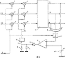
-Fig. 1 represents first embodiment according to conditioning equipment of the present invention;
-Fig. 2 represents second embodiment according to conditioning equipment of the present invention;
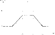
-Fig. 3 represents according to the equipment of prior art with according to the response curve of equipment of the present invention.
In all figure, identical mark is represented components identical.
Embodiment
Fig. 1 represents first embodiment according to conditioning equipment of the present invention.
According to the present invention, conditioning equipment makes the level may adjust luminance component Y and blue CB and red CR aberration chromatic component, and these components are based on to by the colour information item R from matrix 7, G, the peaked detection of one of B supposition, the function of matrix 7 are conversion Y, CB, the CR component is R, G, B component.
Use hereinafter M (R, G, B) expression R, G, the maximum of B, an OR function element is adopted in peaked detection, is labeled as 8, it has three inputs and an output.For this purpose, each R, G, B colour information item is applied to the different inputs of OR function element.OR function element 8 is produced by any known device.For example, it can be to use the circuit that three diodes produce.
The output of OR function element is connected to the first input end of comparator 9.So (R, G B) are applied to the first input end of comparator 9 to value M, and its second input receives the voltage VT2 from multiplier 10.The k that voltage VT2 equals voltage VT1 doubly, k is that user's contrast is adjusted parameter and VT1 is a reference voltage, this value is preferably in factory set.K is preferably between 0.25 and 1 according to the present invention.
The output voltage S that obtains at integrating condenser C two ends is applied to a voltage/coefficient conversion circuit 11 to produce an adjustment factor ks.Voltage/coefficient conversion circuit 11 produces in known mode own.Therefore there is no need here to look back.
Adjustment factor ks is applied to three control input ends of three multipliers 4,5,6 simultaneously, they are at the signal k * Y of their input receptions separately from the multiplier 1,2,3 of three correspondences, k * CB and k * CR, k is that user's contrast above-mentioned is adjusted parameter here.Therefore, be applied to the brightness of transition matrix input, blue difference and red color difference signal equal respectively:
Ks * k * Y; Ks * k * CB and ks * k * CR
According to the present invention, coefficient k s is the value between 0.5 and 1 preferably.
Be that regulating operation is at three signal R, finishes on any one basis among G or the B valuably.
Fig. 2 has showed according to the present invention second embodiment of conditioning equipment.
According to this second embodiment, reference voltage VT1 is directly connected to second input of comparator, and the output of OR function element 8 is connected to the input of divider 12, and the output of divider 12 is connected to the first input end of comparator.Divider 12 is adjusted parameter k control by user's contrast.Therefore, the output voltage of divider 12 equals the input voltage of divider 12 divided by value k.
Those that describe among the every other element of circuit and Fig. 1 among Fig. 2 are identical.Therefore, the circuit operation described of Fig. 2 on principle with Fig. 1 describe identical.But with regard to production, the circuit that Fig. 1 describes has the advantage that does not need to produce divider.According to the circuit that Fig. 1 describes, user's adjustment factor k is applied to 4 multipliers 1,2,3,10 respectively.These four multipliers are preferably identical so, avoided the complexity of circuit like this.Be valuably, k is on the one hand to signal Y, and (acting under optimum condition B) mated for R, G to signal M on the other hand for CB, CR.
Fig. 3 is expression according to the equipment of prior art with according to the response curve of equipment of the present invention.
Fig. 3 comprises three curve C 1, C2 and C3.Curve C 1 and C2 are the response curves according to prior art.
Curve C 1 showed when not having the contrast level adjustment, value M (R, G, B) saturated phenomenon.
The contrast of showing by curve C 1 variation in time changes an example that receives corresponding to video image.It all is possible that the contrast of very clear any other type of example that receives corresponding to other video images changes.According to the example that curve C 1 is showed, (B) the black level VB from moment t1 reaches the white level VW of t2 constantly to value M, remains white level between moment t2 and t3, and reaches the black level VB of t4 constantly at the white level VW of moment t3 for R, G.
Use way of example, curve C 2 has been showed between black level VB and the saturation level VS that fixed by the user and has been worth M (R, G, saturation curve B).
The contrast of showing by curve C 2 variation in time changes corresponding to the condition that receives with those identical video images of curve C 1.
Saturation level VS is regulated by regulating parameter k by the user.If image has high-contrast area, the user just must reduce contrast significantly.Therefore level VS may be the value of a greatly reducing M (R, G, level B).When image no longer included these high-contrast area, then the user must revise his adjusting once more, to recover contrast.For the image that those contrasts alter a great deal, then revising many times for the user, contrast is necessary.
According to the present invention, by means of example, curve C 3 has been showed value M (R, G, saturation curve B) between black level VB and saturation level VT2.
The contrast of showing by curve C 3 variation in time by the mode of example change corresponding to those identical video image condition of acceptances of curve C 1 and C2.
No matter the user what are adjusted into, (R, G B) can not reach the value of white level VW to value M.Be valuably, equipment according to the present invention comprises such as those to be described at Fig. 1 or 2, and (automatic saturated device B) is so that prevent to arrive white level for R, G to be used for implementation value M.This automatic saturation value equals VT2.As above-mentioned, 70% of the corresponding white level VW of the value of VT2.Be that according to equipment of the present invention, the user need not change and to make the comfortable image of eyes and carry out many times adjustment as prior art in order to obtain contrast valuably.
Top description is that reference comprises various colour information item R, G, and the color video frequency image of B carries out.Concerning those are familiar with the people of this area, be applied to the processing of black and white image and no longer be under the situation of coloured image in the present invention, clearly word " monochrome information " can replace word " colour information ".
Claims (8)
1. equipment of regulating the contrast of video image, described equipment comprises:
Conversion equipment (7) is used to make the luminance signal (Y) of video image and blue dyeing degree signal (CB) and red dyeing degree signal (CR) to be converted to red (R), green (G) and blue (B) colour signal;
Checkout gear (8) is used for detecting by the maximum of described red (R) of described conversion equipment (7) output, green (G) and indigo plant (B) signal (M (R, G, B));
It is characterized in that it also comprises:
First installs (1,2,3), is used for regulating in the input of described conversion equipment the amplitude of described luminance signal (Y), described blue dyeing degree signal (CB) and described red dyeing degree signal (CR), regulates parameter (k) with the response user; And
Second device (4,5,6), be used for regulating the amplitude of described luminance signal (Y), described blueness (CB) and described red dyeing degree signal (CR) in the input of described conversion equipment, with response regulation coefficient (ks), so that prevent described maximum (M (R, the G of red, green and blue signal, B)) above saturation value less than white level
Described adjustment factor (ks) is produced by unit (9,10, D, C, A, 11,12), regulates parameter (k) control by described user, to respond described maximum (output and the reference voltage (VT1) of M (R, G, B)) checkout gear (8).
2. equipment according to claim 1, the described unit that wherein is used to produce adjustment factor (ks) comprises having first input end, the comparator of second input and output (9), the first input end of described comparator is connected to described maximum (M (R, G, B)) output of checkout gear (8), second input of described comparator is connected to the output of multiplier (10), and multiplier (10) regulates parameter (k) control by described user and its input is connected to described reference voltage (VT1).
3. equipment according to claim 1, the described unit that wherein is used to produce adjustment factor (ks) comprises having first input end, the comparator of second input and output (9), the first input end of described comparator is connected to the output of being regulated the divider of parameter (k) control by described user, the input of described divider is connected to described maximum (M (R, G, the B)) output of checkout gear (8), and second input of described comparator is connected to described reference voltage (VT1).
4. according to claim 1,2 or 3 described equipment, wherein be used to detect the maximum (M (R of red (R), green (G) and blue (B) signal, G, B)) device (8) comprises the OR function element with three inputs and an output, described each input is connected to different colour signal (R, G, B), and output is connected to described unit.
5. equipment according to claim 1, described first (1,2,3) and second (4,5,6) device of wherein being used to regulate the amplitude of described luminance signal (Y), described blueness (CB) and described red dyeing degree signal (CR) are multipliers.
6. equipment according to claim 1, wherein said user regulates parameter (k) and has value between 0.25 and 1.
7. equipment according to claim 1, wherein said adjustment factor (ks) has the value between 0.5 and 1.
8. equipment according to claim 1,70% of the value of the corresponding white level of wherein said saturation value.
Applications Claiming Priority (2)
| Application Number | Priority Date | Filing Date | Title |
|---|---|---|---|
| FR9607045A FR2749731B1 (en) | 1996-06-07 | 1996-06-07 | DEVICE FOR REGULATING VIDEO IMAGE CONTRAST |
| FR9607045 | 1996-06-07 |
Publications (2)
| Publication Number | Publication Date |
|---|---|
| CN1172396A CN1172396A (en) | 1998-02-04 |
| CN1157945C true CN1157945C (en) | 2004-07-14 |
Family
ID=9492803
Family Applications (1)
| Application Number | Title | Priority Date | Filing Date |
|---|---|---|---|
| CNB971054983A Expired - Fee Related CN1157945C (en) | 1996-06-07 | 1997-06-06 | Device for regulating contrast of video images |
Country Status (6)
| Country | Link |
|---|---|
| US (1) | US5940144A (en) |
| EP (1) | EP0812107B1 (en) |
| JP (1) | JP3892529B2 (en) |
| CN (1) | CN1157945C (en) |
| DE (1) | DE69709576T2 (en) |
| FR (1) | FR2749731B1 (en) |
Families Citing this family (6)
| Publication number | Priority date | Publication date | Assignee | Title |
|---|---|---|---|---|
| JP3494555B2 (en) * | 1997-07-14 | 2004-02-09 | 株式会社日立製作所 | Display device and display method |
| KR100333333B1 (en) * | 1998-12-22 | 2002-06-20 | 윤종용 | Color signal processing device of video signal processing system |
| JP2002077641A (en) * | 2000-08-30 | 2002-03-15 | Matsushita Electric Ind Co Ltd | Facsimile machine |
| EP1380177A1 (en) * | 2001-04-11 | 2004-01-14 | Koninklijke Philips Electronics N.V. | Picture signal contrast control |
| JP2005057621A (en) * | 2003-08-07 | 2005-03-03 | Sanyo Electric Co Ltd | Video signal processing circuit |
| JP4774757B2 (en) * | 2004-09-17 | 2011-09-14 | 株式会社ニコン | Image processing apparatus, image processing program, electronic camera, and image processing method |
Family Cites Families (7)
| Publication number | Priority date | Publication date | Assignee | Title |
|---|---|---|---|---|
| JPH0657066B2 (en) * | 1984-12-20 | 1994-07-27 | キヤノン株式会社 | Color adjustment device |
| JP2515869B2 (en) * | 1988-11-28 | 1996-07-10 | 株式会社日立製作所 | Video signal processing circuit |
| FR2640839B1 (en) * | 1988-12-20 | 1991-03-15 | Portenseigne Radiotechnique | VIDEO IMAGE REPRODUCING APPARATUS HAVING A CONTRAST ADJUSTMENT, AND CONTRAST ADJUSTING METHOD OF SUCH A REPRODUCING APPARATUS |
| US4980756A (en) * | 1989-08-25 | 1990-12-25 | Rca Licensing Corporation | Control signal generator for a television system |
| EP0589513B1 (en) * | 1992-09-22 | 1998-12-02 | Koninklijke Philips Electronics N.V. | Picture signal processor |
| JP2876934B2 (en) * | 1993-05-31 | 1999-03-31 | 日本電気株式会社 | Image contrast enhancement method and apparatus |
| JP3134660B2 (en) * | 1994-04-14 | 2001-02-13 | 松下電器産業株式会社 | Color conversion method and color conversion device |
-
1996
- 1996-06-07 FR FR9607045A patent/FR2749731B1/en not_active Expired - Fee Related
-
1997
- 1997-05-28 JP JP13843197A patent/JP3892529B2/en not_active Expired - Fee Related
- 1997-06-05 DE DE69709576T patent/DE69709576T2/en not_active Expired - Fee Related
- 1997-06-05 EP EP97401260A patent/EP0812107B1/en not_active Expired - Lifetime
- 1997-06-06 US US08/870,616 patent/US5940144A/en not_active Expired - Fee Related
- 1997-06-06 CN CNB971054983A patent/CN1157945C/en not_active Expired - Fee Related
Also Published As
| Publication number | Publication date |
|---|---|
| EP0812107B1 (en) | 2002-01-16 |
| DE69709576T2 (en) | 2002-08-22 |
| JP3892529B2 (en) | 2007-03-14 |
| CN1172396A (en) | 1998-02-04 |
| FR2749731A1 (en) | 1997-12-12 |
| US5940144A (en) | 1999-08-17 |
| JPH1065991A (en) | 1998-03-06 |
| EP0812107A1 (en) | 1997-12-10 |
| DE69709576D1 (en) | 2002-02-21 |
| FR2749731B1 (en) | 2000-08-04 |
Similar Documents
| Publication | Publication Date | Title |
|---|---|---|
| CN101061704B (en) | Color adjusting device and method | |
| CN102611897B (en) | Method and system for carrying out vision perception high-fidelity transformation on color digital image | |
| AU684136B2 (en) | Reproduction circuit for skin color in video signals | |
| US6700559B1 (en) | Liquid crystal display unit having fine color control | |
| CN100586159C (en) | Method and system for processing video frequency signal | |
| CN106504281B (en) | Image quality enhancing and filtering method applied to cmos image sensor | |
| CN101188670B (en) | Device and method for motion and/or scene change detection using color components | |
| CN1157945C (en) | Device for regulating contrast of video images | |
| CN105578094A (en) | Image edge fusion processing system | |
| CN1031094C (en) | Control signal generator for television system | |
| US5302946A (en) | Stacked display panel construction and method of making same | |
| CN101075427B (en) | Image correction circuit, image correction method and image display | |
| CN101873503A (en) | Method and device for adjusting image property | |
| CN101621702A (en) | Method and device for automatically adjusting chroma and saturation | |
| CN100539708C (en) | The method in conversion colors of image space | |
| CN1050487C (en) | Automatic adjusting circuit of analog controlling unit | |
| US5412433A (en) | Secondary color corrector | |
| CN1461571A (en) | Filter device | |
| DE102006050864A1 (en) | Method and apparatus for correcting defective pixels for a solid state imaging device | |
| CN1956550A (en) | Method for regulating color temp effect of TV set | |
| CN1379596A (en) | Using low luminance change over speed to limit and reduce non natural scintillation signal | |
| CN1710931A (en) | Picture colour controlling method and system | |
| EP0524243A4 (en) | ||
| CN101568955B (en) | Method of determining luminance values for a backlight of an LCD panel displaying an image | |
| CN1176552C (en) | Colour difference signal compensation device |
Legal Events
| Date | Code | Title | Description |
|---|---|---|---|
| C06 | Publication | ||
| PB01 | Publication | ||
| C10 | Entry into substantive examination | ||
| SE01 | Entry into force of request for substantive examination | ||
| C14 | Grant of patent or utility model | ||
| GR01 | Patent grant | ||
| C17 | Cessation of patent right | ||
| CF01 | Termination of patent right due to non-payment of annual fee |
Granted publication date: 20040714 Termination date: 20100606 |