JP3891263B2 - Image recording method and image recording apparatus - Google Patents
Image recording method and image recording apparatus Download PDFInfo
- Publication number
- JP3891263B2 JP3891263B2 JP2001342080A JP2001342080A JP3891263B2 JP 3891263 B2 JP3891263 B2 JP 3891263B2 JP 2001342080 A JP2001342080 A JP 2001342080A JP 2001342080 A JP2001342080 A JP 2001342080A JP 3891263 B2 JP3891263 B2 JP 3891263B2
- Authority
- JP
- Japan
- Prior art keywords
- image
- recording
- light source
- recording medium
- dimensional array
- Prior art date
- Legal status (The legal status is an assumption and is not a legal conclusion. Google has not performed a legal analysis and makes no representation as to the accuracy of the status listed.)
- Expired - Fee Related
Links
Images


Landscapes
- Projection-Type Copiers In General (AREA)
- Printers Or Recording Devices Using Electromagnetic And Radiation Means (AREA)
Description
【0001】
【発明の属する技術分野】
本発明は、二次元空間変調素子と光源との組み合わせなどの二次元配列光源を用いた画像記録の技術分野に属し、詳しくは、二次元配列光源を用いた画像記録において、ズームレンズや複数の結像光学系を用いることなく、光学系の収差や各種の光学系の誤差の補正を可能とする画像記録方法および画像記録装置に関する。
【0002】
【従来の技術】
各種のプリンタ等で利用されているデジタルの画像露光においては、レーザビームを主走査方向に偏向すると共に、記録媒体と光学系とを主走査方向と直交する副走査方向に相対的に移動することにより、記録画像に応じて変調したレーザビームで記録媒体を二次元的に露光する、いわゆるレーザビーム走査露光(ラスタスキャン)が主流である。
【0003】
これに対し、近年、ディスプレイやモニタ等における表示手段として利用されている液晶ディスプレイ(以下、LCDとする)やデジタルマイクロミラーデバイス(以下、DMDとする)等の二次元的な画素配列を持つ空間光変調素子を用いるデジタルの画像記録装置が各種提案されている。
この画像記録装置においては、基本的に、空間光変調素子で形成した画像を、記録媒体に投影/結像することにより、記録媒体を露光し、画像を記録する。
【0004】
図20に、DMDを用いる画像記録の一例として、米国特許第5049901号明細書や欧州特許第0992350A1号公報等に開示される画像記録の概略を示す。
周知のように、DMD100は、多数枚のミラー102を配列して構成されるものであり、図示しない光源から出射され、on(画像記録状態)のミラー102で反射された光を結像光学系104によって記録媒体Ptに結像することで、画像記録を行う。
【0005】
図20に示される例において、記録媒体Ptは、DMD100の1つの画素配列方向(図中ミラー102a〜102cの配列方向)と一致する走査方向(図中矢印方向)に搬送されている。
図20(A)においては、DMD100のミラー102aがonで、他のミラー102はoffとなっており、ミラー102aで反射された光のみが記録媒体Ptに結像し、この位置(黒塗りの位置)に画像が記録される。
【0006】
記録媒体Ptが搬送され、ミラー102aによって画像が記録された位置が移動すると、これに応じて、図20(B)に示されるように、ミラー102aがoffになりミラ−102bのみがonになって、記録媒体Pt上の同位置に画像が記録され、さらに記録媒体Ptが搬送されると、図20(C)に示されるように、ミラー102bがoffになりミラ−102cのみがonになって同位置に画像が記録される。
すなわち、この画像記録方法においては、記録媒体Ptの搬送に応じてDMD100による画像表示を切り換えて、DMD100における表示画像を走査方向に移動(シフト)して、搬送される記録媒体Pt上に画像を追随/静止させて、複数のミラー102による多重露光によって、2次元的な画像記録を行う。
【0007】
【発明が解決しようとする課題】
ところで、このような光源と空間変調素子とからなる光学系や、2次元的に配列された光源(以下、これらを二次元配列光源とする)で画像を形成して、この画像を記録媒体に投影/結像する画像記録装置では、二次元配列光源が有する解像度(画素ピッチ)と、結像光学系の倍率とによって、記録する画像の解像度が決定されてしまう。
【0008】
そのため、2次元配列光源の解像度や、光学系の倍率に設計値からの偏差がある場合、記録画像の解像度は、設計値に対し異なったものになってしまうが、この解像度の誤差は補正不可能であるという問題が生じる。
このような解像度の誤差は、主走査や副走査の速度誤差がある場合、温度や湿度などの環境変動により記録媒体や機械部品に寸法誤差が生じた場合、さらに、ドラムスキャナであればドラムの径に誤差がある場合等にも同様に発生する。
また、記録媒体上に投影される2次元配列光源の像は、光学系がもつ歪曲収差(たる型、糸巻き型など)により、歪んでしまう。そのため各画素の位置に誤差を生じ、その結果、画像にスジムラやエッジ部のボケ等を生じてしまい、画像品質の劣化を来たすことになる。さらに、このような画像の歪みは、局面に保持された記録媒体による画像の歪みがある場合、二次元配列光源の配列に不規則性が認められる場合にも同様に発生する問題である。
【0009】
本発明の目的は、前記従来技術の問題点を解決することにあり、光源とDMD等の二次元空間変調素子とを組み合わせた光学系、二次元的に配列された点状の光源によって画像を形成する光学系などの、二次元配列光源を用いる画像記録において、光学系の収差や誤差等に起因する画質劣化のない、高画質な画像を得ることができる画像記録方法および画像記録装置を提供する。
【0010】
【課題を解決するための手段】
前記目的を達成するために本発明の画像記録方法は、二次元的に配列された光源群により形成される画像を、記録媒体に記録するに際し、記録媒体に記録すべき記録画像の1コマ分の画像記録中に、前記光源群による記録媒体上における画像記録位置を、前記光源群の二次元的な配列方向の少なくとも一方の成分を含む方向に移動させると共に、この移動に対応して、記録媒体に記録すべき記録画像の解像度に対する前記光源群の記録媒体上の像の解像度の差異、および前記光源群の投影光を前記記録媒体上に結像させる結像光学系の歪曲収差を加味した前記記録媒体上における二次元配列光源の像の位置と、前記記録媒体に記録すべき記録画像とを比較し、比較結果に基づいて、前記光源群の各画素を均等に時分割しつつ複数回変調し、前記記録媒体に前記解像度の差異および前記歪曲収差による画質劣化が補正された画像を記録することを特徴とする画像記録方法を提供する。
【0011】
また、本発明の画像記録装置は、二次元的に配列された記録画素を有する二次元配列光源と、記録媒体に記録すべき記録画像の1コマ分の画像記録中に、前記二次元配列光源による前記記録媒体上における画像記録位置を、前記二次元配列光源の記録画素配列方向の少なくとも一方の成分を含む方向に移動する移動手段と、前記移動手段による画像記録位置の移動に対応して、記録媒体に記録すべき記録画像の解像度に対する前記二次元配列光源の記録媒体上の像の解像度の差異、および前記二次元配列光源の投影光を前記記録媒体上に結像させる結像光学系の歪曲収差を加味した前記記録媒体上における前記二次元配列光源の像の位置と、前記記録媒体に記録すべき記録画像とを比較し、比較結果に基づいて前記二次元配列光源の各記録画素を変調する変調手段とを有し、前記変調手段は、前記記録画像の1コマ分の画像記録中に前記変調を均等に時分割して複数回行うことを特徴とする画像記録装置を提供する。
【0012】
このような発明において、前記変調手段は、前記記録媒体に記録すべき記録画像に前記二次元配列光源の像の中心が入った前記記録画素を記録可能な状態に変調することが好ましい。
また、前記移動手段は、前記二次元配列光源の記録画素配列方向の両方向の成分を含む方向に前記記録位置を移動することが好ましい。
さらに、前記変調手段は、予め設定された前記結像光学系の歪曲収差が加味された前記記録媒体上における前記二次元配列光源の像の位置を示す関数を用いて、前記比較を行うことが好ましい。
また、前記関数が時間と共に変化することが好ましい。
ここで、前記二次元配列光源と記録媒体とを一方向に相対的に移動する主走査を行う手段と、前記主走査方向と直交する副走査方向に、前記二次元配列光源と記録媒体とを相対的に移動する副走査を行う手段と、前記二次元配列光源による画像記録位置を、前記主走査及び副走査に略追随させる追随手段とを有し、前記二次元配列光源による画像を前記主走査方向及び副走査方向に配列して画像を記録すると共に、前記追随手段による略追随と、前記主走査及び副走査の少なくとも一方との間の相対的な速度差により、前記画像記録位置の移動を行うことが好ましい。
【0013】
【発明の実施の形態】
以下、本発明の画像記録方法および画像記録装置について、添付の図面に示される好適実施例を基に、詳細に説明する。
【0014】
図1に、本発明の画像記録方法を実施する、本発明の画像記録装置の一例の概略斜視図を示す。
図1に示される画像記録装置10(以下、記録装置10とする)は、二次元的に配列された記録画素(光源群)を有する二次元配列光源として、二次元空間光変調素子と、この二次元空間光変調素子を照明する光源とを組み合わせた二次元配列光源を用い、この二次元配列光源と、いわゆるエクスターナルドラム(アウタードラム)とを用いて、DMD12からの投影光を記録媒体Ptに配列することにより、記録媒体Ptを2次元的に露光して画像を記録する装置である。
【0015】
このような記録装置10は、基本的に、照明光を出射する光源(図示省略)と、二次元空間光変調素子であるデジタルマイクロミラーデバイス12(以下、DMD12とする)と、コリメータレンズ14と、光偏向器16と、フォーカシングレンズ18と、副走査駆動系20と、エクスターナルドラム22(以下、ドラム22とする)と、これらの制御手段(図示省略)とを有して構成される。
また、ドラム22の外面には記録媒体Ptが巻き付けられて、公知の手段で保持/固定されている。
【0016】
光源としては、充分な光量の光(照明光)を射出できるものであれば、対象となる記録媒体Ptの分光感度特性に応じた光を出射する各種の光源が利用可能である。
例えば、記録媒体Ptが紫外線による露光が可能な通常のPS版(コンベンショナルPS版)であれば、超高圧水銀灯やメタルハライドランプ等を用いればよい。また、記録媒体Ptが赤外光(熱)に感度を持つヒートモードの記録媒体である場合には、赤外のブロードエリアLD(Broad area Laser Diode)等を用いればよい。これら以外にも、記録媒体Ptに応じて、ハロゲンランプ、キセノンランプ等も利用可能である。
【0017】
周知のように、DMD12は、所定の回転軸を中心に所定角度回転(揺動)可能な矩形のマイクロミラーを、二次元的に配列してなる二次元空間光変調素子で、静電的にマイクロミラーを回転することにより、各マイクロミラー(=画素)毎に光を変調して、露光をon/offする。図示例の記録装置10においては、一例として、画素間隔が17μmで、1024画素×1280画素のDMD12を用いている。
また、後述するドラム22の回転方向(図中矢印R方向)とDMD12の1つの画素列方向とが光学的に一致し、かつ、ドラム22の軸線と他方の画素列方向とが光学的に一致するように、各部材が配置される。以下、ドラム22の回転と逆方向のDMD12の画素列方向(図中矢印Y方向)を主走査方向、ドラムの軸線方向の図中右方向(図中矢印X方向)を副走査方向とする。
【0018】
前述のように、図示例においては、DMD12と光源とを組み合わせることにより、二次元配列光源を構成している。ここで、本発明においては、二次元配列光源を構成する二次元空間光変調素子は、DMD12以外にも、例えば、液晶シャッタを二次元的に配列してなる液晶シャッタアレイ、PLZTタイプ、EOタイプ、AOタイプ、GLVタイプ等も利用可能である。
また、本発明において、二次元配列光源は、このような光源と空間光変調素子とを組み合わせたものに限定はされない。例えば、LEDなどの点状の光源を二次元的に配列してなるアレイ状光源、CRTやバックライト型LCD(液晶ディスプレイ)などの自己発光型のディスプレイ等を、二次元配列光源として用いてもよい。
しかしながら、二次元配列光源としては、変調速度や光の利用効率等の点で、DMD12と光源とを組み合わせたものが、最も好ましい。
【0019】
コリメータレンズ14は、DMD12によって反射された画像を担持する光を平行光として、光偏向器16に入射させるものである。
【0020】
光偏向器16は、コリメータレンズ14を介して入射された光を、ドラム22の略回転方向に偏向することにより、図1に模式的に示されるように、DMD12による投影光の記録媒体Ptへの入射位置(画像記録位置)を、主走査される記録媒体PtにDMD12からの投影光を追随させる、追随手段である。
すなわち、光偏向器16は、基本的に、ドラム22の回転に同期して、画像を担持するDMD12からの投影光をドラム回転方向に偏向することにより、この投影光を回転される記録媒体Ptに追随させ、所定の記録時間(露光時間)だけ記録媒体Pt上の一定位置に静止させる。
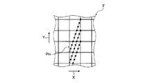
以下の説明においては、記録媒体Pt上におけるDMD12の投影光をコマF、光偏向器16の偏向によって記録媒体Pt上に静止されたコマFによる1回の画像記録を1コマの記録とする。従って、1コマは、DMD12による記録媒体Pt上の1画面(DMD12が一度に露光可能な範囲)のサイズとなる。
【0021】
ここで、本発明においては、画像記録中(露光中)に、記録媒体Pt上における画像記録位置を二次元配列光源の画素配列方向の少なくとも一方を含む方向に移動させる。
記録装置10においては、DMD12の画素配列方向と、主走査方向および副走査方向とが光学的に一致するように、光学系が構成されており、好ましい態様として、記録媒体Pt上に静止させて行う1コマの画像記録中における、主走査および副走査とコマFの追随との間に相対速度差を持たせることにより、主走査方向および副走査方向の両成分(以下、主副両成分とする)を含む方向にコマF(DMD12からの投影光の入射位置)を移動する。以下、この1コマの記録中におけるコマFの移動を「コマFをシフト」という。
【0022】
図示例の記録装置10においては、より好ましい態様として、追随手段である光偏向器16が、コマFをシフトする移動手段を兼ねる。そのため、光偏向器16の偏向方向は、回転方向(主走査方向)に対して、若干の角度を有しており、これにより、主/副の走査と、自らによるコマFの追随との間に、相対速度差を持たせている。この点については、後に詳述する。
【0023】
光偏向器16は、ガルバノメータミラー、ポリゴンミラー、ピエゾシステム、レンズをドラム22の回転方向にシフトする光偏向器等、各種のものが利用可能である。図示例の記録装置10においては、好適な一例として、ガルバノメータミラー(以下、ガルバノミラーとする)を用いている。
【0024】
フォーカシングレンズ18は、光偏向器16によって偏向されたDMD12の投影光を、ドラム22に巻き付けられた記録媒体Pt上の所定位置に結像させるものである。
【0025】
ドラム22は、その外側面に記録媒体Ptを巻き付けた状態で、公知の方法で保持/固定すると共に、軸を中心として、主走査方向と逆の図中矢印R方向に回転する円筒である。これにより、DMD12(二次元配列光源)と記録媒体Ptとが、主走査方向に相対的に移動する(すなわち、主走査を行う)。
なお、本発明において、対象となる記録媒体Ptには特に限定はなく、感光材料でも感熱材料でもよく、また、フィルム状でもプレート状でもよい。
【0026】
光源からDMD12、コリメータレンズ14、光偏向器16、およびフォーカシングレンズ18に至る光学系は、一体的にユニット化されており、副走査駆動系20により、副走査方向(図中矢印X方向)に一定速度で移動する。これにより、DMD12と記録媒体Ptとが、副走査方向に相対的に移動する(すなわち副走査を行う)。
副走査駆動系20は、いわゆるドラムスキャナ等に利用される公知のものであり、例えば、図示しない駆動源と、ユニット化された光学系を積載する移動台20aと、この移動台20aがその上を移動する、副走査方向に延在する移動軸20bとからなっている。
【0027】
なお、本発明において、記録媒体Ptを保持して、主走査や副走査を行う手段は、図示例のような(エクスターナル)ドラム22に限定はされず、フラットベッドでも、記録媒体Ptを内面で保持するインターナルドラムでもよい。
【0028】
図2に、記録装置10の記録タイミング制御のブロック図を示す。
図2に示すように、光源24、DMD12、光偏向器16(図2では、コリメータレンズ14、フォーカシングレンズ18は省略)等の光学系は一体化して構成され、少なくとも画像記録の際には、副走査駆動系20によって副走査方向Xに一定速度で連続的に移動するようになっている。
【0029】
前述のように、画像記録中は、記録媒体Ptを保持するドラム22が回転すると共に、光偏向器16は、コマF(DMD12による投影光)を、ドラム22の回転に同期して略主走査方向に偏向することにより、コマFを所定の記録時間だけ記録媒体Pt上に静止させて、1コマの記録を行う。また、画像記録中は、光学系のユニットは、副走査駆動系20によって副走査方向に搬送される。
そのタイミングを制御するために、主走査位置検出器26がドラム22に設けられると共に、副走査駆動系20には、副走査位置を検出する副走査位置検出器28が設けられている。主走査位置検出器26としては、例えば、ドラム22の回転位置を検出するロータリーエンコーダを用いることができる。
【0030】
DMD12には、1コマ分の画像データ(各マイクロミラーのon/off)を供給する変調信号発生器30が接続される。変調信号発生器30には、画像信号が入力され、主走査位置検出器26および副走査位置検出器28からの検出信号に基づいて、DMD12に送る画像信号が切り換えられる。
また、光偏向器16には、光偏向器ドライバ32が接続される。光偏向器ドライバ32は、主走査位置検出器26および副走査位置検出器28の検出信号に基づいて、光偏向器16を駆動し、DMD12による投影光を、記録媒体Ptの相対移動に合わせて偏向させる。
【0031】
このような記録装置10においては、前述のようにして光偏向器16によって追随させて記録媒体Pt上に静止して記録した1コマの画像を、記録媒体Ptの画像記録領域に二次元的に配列するようにして、画像を記録する。
【0032】
ここで、画像記録は、副走査を停止した状態でドラム22を一周して、DMD12による1コマの画像を主走査方向(Y方向)に1列形成した後に、副走査駆動系20によって1コマの副走査方向(X方向)のサイズ分だけ副走査方向にDMD12(光学系)を移動して、再度、主走査方向への1列の画像記録を行うことを繰り返すことにより、記録媒体Ptの全面にコマFを配列して画像を記録してもよい(この際には、副走査速度は0)。
しかしながら、図示例においては、1画像の記録時間の短縮や、副走査駆動系20にかかる負担を低減するために、好ましい態様として、前述のように、連続的に副走査を行いつつ画像記録を行って、ドラム22に巻回した記録媒体PtにコマFをスパイラル状に配列して、全面に画像記録を行う。
【0033】
すなわち、図示例の記録装置10においては、ドラム22の回転速度(主走査速度)に応じて、ドラム22が一周した時点で、記録すべきコマFが先に記録したコマFと副走査方向に隣り合わせるように、副走査駆動系20による副走査速度を設定する。
これにより、ドラム22に巻回された記録媒体Ptにスパイラル状に画像記録を行い、記録媒体Ptを展開した図3の概念図に示されるように、コマFを主走査方向に階段状に配列して、記録媒体Ptの全面に画像記録を行う。なお、図3においては、下方がドラム22の1回転目における記録を、上方が同2回転目における記録をそれぞれ示すものであり、また、Ldrは、ドラム22の一周の長さを示す。この記録方法は、本出願人による特願2000−316622号の明細書に詳述されている。
【0034】
ここで、図示例の記録装置10においては、前述のように、ドラム22の回転に同期して、光偏向器16によってDMD12の投影光を主走査方向に偏向することにより、記録媒体Pt上にコマFを静止して1コマの記録を行う。
ところが、副走査を連続的に行いながら画像記録を行うと、主走査方向には光偏向器16による偏向でコマFを停止できても、記録媒体Pt上におけるコマFの位置が副走査方向に動いてしまい、画像がボケてしまう。
そのため、記録装置10においては、副走査によるコマFの位置ズレに応じて、主走査方向に対して偏向方向を副走査方向に向けて傾け、1コマの記録中に、より好適に、コマFを記録媒体Ptに静止させるのが好ましい。
【0035】
ここで、この主走査方向(矢印Y方向)に対する偏向方向の角度は、1コマを記録した後、次に記録するコマFが、副走査方向の画素ピッチ(記録媒体Pt上における画素ピッチ)の整数倍だけ副走査方向に移動するように設定するのが好ましい。
中でも特に、前記画素ピッチの整数倍をNy、1コマの主走査方向の画素数をNimg-y 、1コマの主走査方向の画素ピッチをPimg-y 、1コマの副走査方向の画素ピッチをPimg-x とした際に、主走査方向に対する偏向方向の角度ψが下記式を満たすようにするのが好ましい。
tanψ=(Ny×Pimg-x )/(Nimg-y ×Pimg-y )
この画像記録方法については、本出願人による特願2001−116470号の明細書に詳述されている。
【0036】
以上のように、記録装置10においては、コマF(DMD12の投影光)を記録媒体Ptの移動に追随させ、基本的に、所定の記録(露光)時間だけ記録媒体Pt上に静止させた状態で、1コマの画像記録を行う。
ここで、図示例の記録装置10は、本発明にかかるものであり、主走査および副走査と静止のためのコマFの追随との間に相対的な速度差を持たせることにより、図4に概念的に示すように、1コマの記録中に、記録媒体Pt上における画像記録位置すなわちコマFの位置を、主副両成分を含む方向(矢印V方向)にシフトする。また、このコマFのシフトと共に、1コマで記録する画像に応じて、記録媒体Pt上において、画像を記録すべき位置にDMD12の画素(ミラー)が位置した際に、この画素をonするように、DMD12による表示画像を変調する。言い換えれば、記録媒体Ptと光学系との主走査および副走査に対応した静止のためのコマFの移動に、相対的な速度差を持たせ、かつ、これに伴ってDMD12の各画素を記録する画像に応じて変調する。
本発明においては、このような構成を有することにより、二次元配列光源を用いた画像記録において、解像度の補正等を可能にしている。
【0037】
以下、図5〜図7を参照して、記録装置10(本発明)における画像記録の作用を説明する。
図5(A)に、記録媒体Pt上におけるDMD12によるコマFの一部を、図5(B)に、記録媒体Ptに記録する画像の解像度の一例を、それぞれ概念的に示す。共に、1マスが1画素であり、すなわち記録媒体PtにおけるコマFの1画素(DMD12の分解能)と、目的とする画像の1画素(記録の解像度)とは異なり、コマFの方が小さく、記録媒体Pt上におけるコマFの各画素と記録画像とは、図5(C)に示される関係となる。
【0038】
本例においては、記録画像に中心が含まれるDMD12の画素(ミラー)をonして、画像を記録する。すなわち、例えば、記録する画像が図5(B)および(C)に太枠で示す画像であれば、黒点で示す中心が画像記録領域に含まれる、クロスハッチで示されるDMD12の画素をonにする。
ここで、前述の1コマの記録中における主副両成分を含む方向へのコマFのシフトによって、画像記録領域に中心が含まれる画素が変わる。本発明においては、それに応じて、DMD12による表示画像を切り換える、すなわち変調することにより、画像を記録する。
【0039】
以下、図5(A)に示されるDMD12によるコマF(DMD12の投影光)の一部による、図5(B)に太枠で示される画像の記録について、図6〜図8を参照して、その一例を説明する。
本例においては、一例として、図4に示されるように、1コマの記録中に、主走査方向(矢印Y方向)に対して3画素分、副走査方向(矢印X方向)に対して1画素分、コマFをシフトする。すなわち、主走査方向:副走査方向=3:1でコマFをシフトして、画像記録を行う。なお、本例においては、一例として、実際のコマFの移動方向は主走査方向および副走査方向とは逆方向であるが、本発明はこれに限定はされない。
また、1コマの記録において、記録時間(露光時間)を均等に時分割して、DMD12の表示画像を9回変更すなわち9回の変調を行う。
【0040】
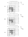
一例として、図6(A)に示される状態から1コマの記録を開始する。この状態では、太枠で示す記録画像の領域には、DMD12の画素a−3,b−3およびc−1〜3の中心が含まれているので、クロスハッチで示すように、この画素をonして画像を記録する。
【0041】
前述のように、ドラム22に保持される記録媒体Ptは主走査方向と逆方向に回転されている。また、コマFは、光偏向器16によって同方向に偏向されることにより、基本的に記録媒体Ptに追随/静止されつつ、前記3:1の割合で主副両成分を含む方向にシフトしている。
1コマの記録時間の1/9が経過、すなわち、主走査方向(矢印Y方向)に対して3/9画素分、副走査方向(矢印X方向)に対して1/9画素分、コマFがシフトすると(以下、単に「コマFが所定量シフト」とする)、図6(B)に示されるように、DMD12が変調されて、画像(投影像)が切り替わる。すなわち、記録開始状態では含まれていた画素a−3の中心が記録画像領域から外れるので、図6(A)に示される状態から、この画素のみがoffされる。
【0042】
さらにコマFが所定量シフトすると、図6(C)に示されるようにDMD12が変調されて、記録画像領域から中心が外れた画素c−1がoffされ、新たに中心が記録画像領域に入った画素d−2および3がonされる。
さらにコマFが所定量シフトすると、図7(D)に示されるようにDMD12が変調されて、記録画像領域から中心がはずれた画素c−2がoffされる。
【0043】
以下、同様にして、図7(E)〜図8(I)に示されるように、コマFが所定量シフトする毎に、DMD12が変調され、中心が記録画像領域を外れた画素がoff、中心が記録画像領域に入った画素をonして、画像を記録する。
最後に、図8(I)に示される状態からコマFが所定量シフトして、図9に示される状態となると、主走査方向に3画素、副走査方向に1画素、コマFがシフトして、すなわち1コマの記録が終了し、全画素がoffされて、記録媒体Ptの移動(ドラム22の回転)および光偏向器16の状態に応じて、主走査方向に隣り合わせるようにして、次の1コマの画像記録が開始される。
【0044】
すなわち、図6(A)〜図9の1コマの記録では、図6(A)〜図8(I)において、クロスハッチで示した領域を重ねたように記録が行われ、すなわち、図10に概念的に示されるように、画像の記録が行われる。
なお、図10に示されるように、本発明の画像記録方法では、目的とする記録画像の理想的な解像度を若干超える領域まで画像記録が行われるが、記録は、目的とする画像記録領域に集中しており、はみ出した部分の記録(露光)量は、若干であるので、画質的に問題にはならない。
【0045】
従来の二次元配列光源を用いた画像記録では、二次元配列光源の1画素(図示例においては、DMD12の投影光の1画素)の整数倍の解像度しか表現することができない。そのため、DMD12(二次元配列光源)のピッチ誤差や結像光学系に設計値からの誤差がある場合、ドラム22の径に誤差がある場合、主走査や副走査速度に誤差がある場合、さらには、温度や湿度等の環境変動によって、記録媒体Ptや機械部品に寸法誤差が生じた場合には、記録画像の解像度は、これらの誤差を反映してしまい、設計値に対し異なるものになっていた。 また、これらを補正するためには、ズームレンズや補正用の結像光学系を準備する必要があった。
【0046】
これに対し、以上の説明より明らかなように、本発明によれば、DMD12等を利用する二次元配列光源を用いた画像記録において、コマF(二次元配列光源の投影光)を主副両成分を含む方向にシフト(移動)すると共に、記録する画像に応じて二次元配列光源を変調することにより、いわゆる走査露光と同様の画像記録を行うことができる。
すなわち、本発明によれば、二次元配列光源の解像度によらず、目的とする解像度および画像に応じて、二次元配列光源の各画素を変調することで、ズームレンズ等を用いなくても、任意の解像度での画像記録を行うことができる。
従って、結像光学系の誤差、DMD12のピッチ誤差、温度/湿度などの変動による記録媒体Ptや機械部品の寸法誤差等を予め知見しておき、それによる解像度の誤差を加味して、例えば記録媒体Pt上におけるDMD12の各画素の結像位置を知見(算出)して、前述のように目的とする解像度の画像に応じて変調を行うことにより、解像度の誤差を生じない高画質な画像を得ることができる。さらにこのようなコマのシフトに応じた変調を、目的とする解像度の画像に応じて行うことにより、任意の解像度の画像を記録することができ、すなわち、解像度変換も容易に行うことができる。
【0047】
さらに、このような、DMD12(二次元配列光源)によるコマをシフトして画像記録を行う本発明によれば、前述の解像度の誤差のみならず、光学系(主にフォーカシングレンズ18)が有する歪曲収差に起因する画質劣化も補正(以下、歪曲収差の補正とも言う)することができる。
【0048】
周知のように、レンズは歪曲収差(糸巻型やたる型等)を有するため、記録媒体Ptに結像したコマも、それに応じて歪んでしまう。従って、このようなコマを図3に示されるように配列して画像を形成すると、歪曲収差による歪みに応じて、コマ(像)が投影されない領域や、複数のコマが重複してしまう領域が生じ、結果的に、画像にスジ状のムラ等を生じてしまう。
これに対し、DMD12によるコマを走査して露光を行う本発明によれば、予め、光学系が有する歪曲収差の状態を知見して、それに応じてDMD12の各画素変調することにより、歪曲収差を補正した、適正な画像を記録できる。
【0049】
例えば、1コマの記録において、図11(A)に示されるように、a、bおよびcで示される3箇所に前述と同様の3画素の鍵型の画像を記録する。
この際において、DMD12によるコマFが、図11(B)に示されるようなフォーカシングレンズ18による歪曲収差(図示例は、糸巻型)による歪みを有して記録媒体Ptに結像するとする。一方で、図11(A)における位置aの画像は、図11(B)に示すDMD12によるコマFの円aで示される領域に、同位置bの画像は同円bで示される領域に、同位置cの画像は同円cで示される領域に、それぞれ記録される。図11(B)に示すように、位置bおよび位置cでは、歪曲収差によって、画像が歪んでいる。
【0050】
このような収差によるコマFの歪みを予め知見しておき、これに応じて、DMD12の変調を行う。
具体的な一例として、歪曲収差によるコマFの歪みを予め知見しておくことにより、これを加味した上で、コマのシフトに応じた各変調時(前述のコマが所定量シフトされた位置)における、DMD12の各画素(その中心)の記録媒体Pt上の位置を知ることができる。従って、これに応じて、先の例と同様に、記録すべき画像に中心が含まれるDMD12の画素をonすることにより、歪曲収差を補正した、適正な画像を記録することが可能になる。
【0051】
一例として、先の図4から図10に示される例と同様に、主走査方向:副走査方向=3:1でコマFをシフトして、均等な9回の変調で1コマを記録する。
この際において、図11に示される画像を記録すると、収差によるコマの歪みが無い図11における位置aの画像記録は、図12(A)に示されるようになり、すなわち、前述の図6〜図8に示される記録と同様になる。
なお、図12おける各位置での記録は、上から順に、前記図6(A)〜図8(I)に対応するのは、言うまでも無い。
【0052】
一方、コマFの位置bは、歪曲収差によって若干の歪みを有し、さらに、コマFの位置cは、さらに大きな歪みを有する。
しかしながら、前述のように、本例においては、この歪を予め知見しているので、これを加味した上での、各変調時における記録媒体Pt上のDMD12の各画素の位置を知見することができ、それに応じて、コマが所定量シフトされた各変調位置において、記録する画像にコマFの中心が入った画素をonする。従って、位置bにおけるDMD12の各画素の変調は図12(B)に示されるように、他方、位置cにおけるDMD12の各画素の変調は図12(C)に示されるようになる。
【0053】
図12に示される画像記録において、DMD12のonされた画素のみを抽出すると、図13の(A)、(B)および(C)に示されるようになり、従って、a、bおよびcの各位置における鍵型の画像は、図14(A)、(B)および(C)に示されるようになる。
すなわち、本発明によれば、コマのシフトを利用することにより、先の例と同様に、画質的に問題とはならない若干のはみ出しは有するものの、図14に示されるように、光学系の有する歪曲収差を補正した、適正な画像を記録することができる。
【0054】
以下、コマFをシフトしながらDMD12(二次元配列光源)の各画素を変調する際に、像記録結像光学系の誤差、DMD12のピッチ誤差等を予め知見しておき、それによる解像度の誤差を加味した変調方法について、図15を参照して、その一例を説明する。また、図16に、この変調方法を実行する制御ブロック図の一例を示す。
【0055】
図15の左上段に示されるように、DMD12における画素配列方向において、一方向にi番目で、他方向にj番目の画素を、画素(i,j)とする。なお、図示例においては、iは副走査方向(X方向)に、jは主走査方向(Y方向)に対応する。また、このDMD12の主走査方向の画素ピッチをΔy、副走査方向の画素ピッチをΔxとする。
従って、(i*Δx,j*Δy)によって、この画素(i,j)の中心位置(xi ,yj )を得ることができる。
【0056】
副走査方向のシフト量を示す関数をFx、同主走査方向のシフト量を示す関数をFyとする。これに応じて、1コマの記録中の時間tにおける、DMD12の前記画素(i,j)の中心位置(xi ,yj )の投影像上の位置は、(Fx(xi ,yj ,t),Fy(xi ,yj ,t))で示すことができる。以下、この位置を、像中心位置(Xi ,Yj )とする。
図16に示すブロック図においては、この関数FxおよびFyに対応するシフト量決定LUT(ルックアップテーブル)を用いて、像中心位置(Xi ,Yj )を得ている。
【0057】
なお、本発明において、この関数FxおよびFy(決定LUT)は、コマFのシフト量のみならず、予め知見したDMD12のピッチ誤差、温度変動等による機械部品の寸法誤差等を加味して設定する。これにより、二次元配列光源を利用する画像記録において、解像度誤差を補正した、適正な解像度の画像を記録することができる。あるいは、この関数FxおよびFyを、前述のようにフォーカシングレンズ18等の歪曲収差を予め知見して、これ加味して決定することにより、歪曲収差を補正した高画質な画像を記録できる。
さらに、本発明においては、このような解像度誤差、および、歪曲収差の両方を補正するように、画像記録を行うのが好ましいのは、もちろんのことであり、関数FxおよびFyは、解像度誤差および歪曲収差の両者を知見した上で、これを考慮して決定してもよい。
【0058】
なお、温度変動等による記録媒体Ptの寸法等は、時間と共に変化する場合があり、すなわち、解像度の誤差等も、時間と共に変化する場合がある。
従って、この関数FxおよびFyは、経時と共に変化(変更)させてもよい。この関数の変化は、環境温室度等の測定結果に応じて行ってもよく、また、予め設定されたシーケンスに応じて行ってもよく、また、両者を併用してもよい。
【0059】
一方、記録する画像の出力解像度における、主走査方向の画素ピッチをΔY、同副走査方向の画素ピッチをΔXとする。
前述のように、DMD12の画素(i,j)の中心位置(xi ,yj )は、投影像上では像中心位置(Xi ,Yj ) となる。従って、像中心位置を画素ピッチで除すことにより、その像中心位置が記録画像のビットマップ上の何処の画素に位置するかを知る事ができ、(round[(Xi /ΔX)] ,round[(Yj /ΔY)]) が、記録する画像の画像ビットマップ上におけるon画素(mon,non)に対応する場合に、画素(i,j)をonするようにDMD12を変調すれば、図6〜図9等で例示したような画像記録を行うことができる。なお、上記式において、「round 」は四捨五入を示す。また、本例では、一例として、画像ビットマップでは、mが副走査方向に、nが主走査方向に対応する。
【0060】
ここで、記録装置10のような二次元配列光源を用いた画像記録においては、各画素の投影像サイズのバラツキ、光強度のバラツキ、位置誤差等に起因して、シェーディングが発生する。シェーディングは、例えば、印刷物であれば、再現された網%のバラツキ(面積率の位置によるローカリティ)となり、画像品質上問題であり、補正が必要である。
通常、シェーディングの補正は、各画素の光強度補正によって行われるが、コマFをシフトして記録を行う本発明の記録方法によれば、強度補正ではなく、面積率の直接的な補正によって、シェーディングを補正できる。
【0061】
前述の像中心位置を画素ピッチで除した位置((Xi /ΔX,Yj /ΔY) 以下、これをDMD像とする)と、画像ビットマップ上におけるon画素(mon,non)とにおいては、対応する方向の差分の絶対値は、すなわち、DMD像とon画素との中心位置のズレを示している。
従って、この絶対値と、主副のそれぞれに対応して適宜設定された閾値Thr(正の数)とを比較し、主副両方向の絶対値が閾値Thr以下である場合に、DMD12の画素(i,j)をonするように変調を制御することにより、記録画像の面積率を制御することができる。
すなわち、|(Xi /ΔX)−mon|≦Thrm
|(Yj /ΔY)−non|≦Thrn
を共に満たす場合に、DMD12の画素(i,j)をonするように変調を制御することにより、記録画像の面積率を制御することができる。
【0062】
閾値は、光学系の有するシェーディングに応じて、適宜決定すればよい。
例えば、Thrm =Thrn =0.5とすれば、先に示した補正を行わない標準的な画像記録となり、すなわち、DMD像(Xi /ΔX,Yj /ΔY) が、画像ビットマップのon画素(mon,non)の中に存在した場合に、DMD12の画素(i,j)をonする例となる。
他方、Thrm =Thrn =0.6とすれば、DMD像が、画像ビットマップのon画素から0.1画素分外れても、その画素がonになるので、面積率を大きくできる。
逆に、Thrm =Thrn =0.4とした場合には、DMD像が画像ビットマップのon画素に対して0.1画素分小さい領域に存在しないと、その画素がonにならないので、面積率が小さくなる。
さらに、Thrm とThrn とを異なる値にした場合には、主走査方向と副走査方向(画像の縦横)とで、面積率を制御することができる。
【0063】
なお、この変調方法では、DMD12(二次元配列光源)による像を記録媒体Ptに写像し、記録媒体Ptに記録すべき画像パターンと記録媒体Pt上におけるDMD12の各画素像位置と比較することによりDMD12の各画素のon/offを決定したが、本発明はこれに限定されず、逆に記録媒体Ptに記録するパターンを二次元配列光源に写像して、DMD12の各画素のon/offを決定してもよい。
【0064】
図17に、前述の図6〜図9等に示される画像記録における、記録媒体Pt上におけるDMD12の各画素(ミラー)の動きを概念的に示す。
前述のように、この例では、1コマの記録において、副走査方向:主走査方向=1画素:3画素でコマFをシフトして、9回の変調を均等に時分割して行うので、DMD12の各画素は矢印に示されるように移動し、例えば、点の位置で変調が行われる。
矢印で示す1画素の画素位置Pixに注目すると、この画素位置Pixでは、1コマの画像記録において、3つの画素(DMD12のミラー)が、副走査方向に均等の間隔で、主走査方向に対して端部から端部まで進行し、それぞれが、均等の間隔すなわち位相を揃えて3回変調される。すなわち、この例では、1コマの記録開始時における画素位置において、1画素につき、主×副走査方向で均等に3×3の9画素の画像を記録したことになり、従って、DMD12の解像度の9倍相当(一方向に3倍)の解像度の画像記録を行っている。本発明においては、これにより、前述のような歪曲収差の補正や、温度変動等による解像度誤差の補正を可能にしている。
【0065】
ここで、本発明の記録装置10において、このような、1コマの記録におけるコマFのシフトにおいて、シフトの方向および量は、特に限定はなく、記録する画像の解像度等に応じて、適宜、決定すればよい。また、シフトの方向および量は、固定されていても、可変であっても、適宜設定可能であってもよい。
さらに、図示例においては、コマFのシフトは、主/副走査方向に対して逆方向に行ったが、本発明は、これに限定はされず、主/副走査方向に対して順方向にコマFをシフトしてもよく、あるいは、主走査方向には順方向で副走査方向には逆方向等であってもよい。
【0066】
ここで、DMD12の画素(画素ピッチ)を単位として、A方向およびB方向の何れの方向にも、1画素以上、移動するのが好ましい。
特に、A方向およびB方向のシフト画素数を、一方が1で他方を2以上の整数、もしくは、互いに素の1以上の整数とし、大きい方のシフト画素数の二乗回の変調を均等に時分割して行うのが好ましい。
あるいは、上記条件を満たした上で、目的とする解像度の変更倍率に対応するA方向の解像度の変更倍率をa、同B方向の変更倍率をbとした際に、1コマの記録において、A方向にはb画素でB方向にはそれ以下の画素数で、もしくは、B方向にはa画素でA方向にはそれ以下の画素数でコマFのシフトを行い、さらに、a×b回の変調を均等に時分割して行うのも、好ましい。なお、この際においても、A方向およびB方向のシフト画素数を、一方が1で他方を2以上の整数、もしくは、互いに素の1以上の整数とするのが好ましい。
【0067】
上記条件を満たすことにより、DMD12の記録解像度を効率良く向上して、前述の図5〜図10等に示されるような解像度や歪曲収差の補正を行った画像記録を、好適に行うことができる。なお、上記条件におけるA方向およびB方向は、何れが主走査方向でも副走査方向でもよい。
【0068】
このようなコマF(投影光)のシフトを行う方法、すなわち、1コマの記録中に、主/副走査とコマFの追随との間に相対速度差を持たせる方法には、特に限定はなく、各種の方法が利用可能である。
例えば、光偏向器12を利用する方法、主走査速度(ドラム22の周速度)とコマFの静止のための追随とに速度差を付ける方法、副走査速度と光偏向器による副走査方向への追随速度とに差をつける方法、記録媒体Pt(図示例ではドラム22)を移動する方法、光学系を移動する方法、これらを組み合わせる方法、等が例示される。
【0069】
前述のように、記録装置10においては、好ましい態様として、1コマの記録におけるコマFの追随手段である光偏向器16が、コマFのシフト(移動)手段も兼ねている。そのため、光偏向器16によるDMD12の投影光の偏向方向は、主走査方向に対して、若干、副走査方向に傾いている。
これにより、主走査および副走査に対して、記録媒体Ptに対するコマFの追随に相対速度差を持たせ、1コマの記録中にコマFを主副両成分を含む方向にシフトさせている。
【0070】
ここで、この光偏向器16による偏向方向等は、一例として、目的とするシフト量および方向、あるいはさらに、前述の角度ψ等に応じて、以下のように決定すればよい。
【0071】
ドラム22の周速度すなわち主走査速度をVyとすれば、1コマの記録において、記録媒体Pt上の或る一点の或る時間tにおける主走査方向(矢印Y方向)の位置Y(t)は、図18(A)に示されるように、「Y(t)=−Vy*t」となる。
一方、記録媒体Pt上における光偏向器16(図示例では、ガルバノミラー)による偏向速度をVy’とすると、1コマの記録において、記録媒体Pt上の或る画素(DMD12の画素)の或る時間tにおける主走査方向の位置Y’(t)は、同図に示すように、「Y’(t)=−Vy’*t」となる。なお、図示例においては、光偏向器16がガルバノミラーであるので、記録時間Tを過ぎた時点で逆方向に揺動し、位置は一点鎖線で示されるようになる。
【0072】
ここで、1コマの記録時間をTとすると、前述の1コマの記録における主走査方向のシフト量は両者の差分ΔYで示すことができる。
すなわち、 ΔY=Y’(T)−Y(T)
ΔY=−Vy’*T−(−Vy*T)
Vy’=Vy−(ΔY/T)
【0073】
他方、1コマの記録において、記録媒体Pt上の或る一点の或る時間tにおける副走査方向(矢印X方向)の位置は移動しない。
一方、副走査駆動系20による副走査速度をVxとすると、これに起因する或る時間tにおける或る画素の副走査方向の位置X(t)は、図18(B)に示すように、「X(t)=Vx*t」となる。さらに、或る画素の光偏向器16による副走査方向への移動速度をVx’とすると、これに起因する或る時間tにおける或る画素の副走査方向の位置X’(t)は、同図に示すように「X’(t)=Vx’*t」となる。
【0074】
同様に、1コマの記録時間をTとすると、前述の1コマの記録における副走査方向のシフト量は両者の差分ΔXで示すことができる。
すなわち、 ΔX=X’(T)−X(T)
ΔX=Vx*t−Vx’*t
Vx’=Vx−(ΔX/T)
【0075】
光学系(DMD12)から見た場合には、記録媒体Pt上における或る一点は、副走査速度Vxとドラム22の周速度Vyによって決まる。
従って、図18(C)に示されるように、記録時間がTである1コマの記録においては、主走査速度および副走査速度によるVx*TおよびVy*Tで決まる地点から、目的とするシフト量に応じたΔXおよびΔYだけズレた位置に向かって偏向を行うように、光偏向器16を設定すればよい。
【0076】
ここで、主走査方向と光偏向器16の偏向方向とが成す角度をθ、光偏向器16の偏向速度をVgとすると、
「Vx’=Vg*sinθ」および「Vy’=Vg*cosθ」
従って、
tanθ=(Vx’/Vy’)
=[Vx−(ΔX/T)]/[Vy−(ΔY/T)]
=(Vx*T−ΔX)/(Vy*T−ΔY)
となる。すなわち、これを満たすように、光偏向器16の角度、主走査速度(ドラム22の回転速度)、副走査速度等を設定すれば、1コマの記録において、目的とする主副両成分を含むコマFのシフトを行うことができる。
【0077】
ここで、前述のように、コマFのシフトの方向は、主/副走査方向に対して順方向であっても、逆方向であってもよい。従って、ΔXおよびΔYは、正/負の何れも取り得るものであり、すなわち、コマFのシフトの方向に応じて、
tanθ=(Vx*T±ΔX)/(Vy*T±ΔY)
を満たすように、光偏向器16の角度等を設定すればよい。
【0078】
このような追随走査によって、コマFを記録媒体Pt上に静止させて1コマの記録(露光)を行う画像記録において、光偏向器16によって偏向されるコマFをシフトする方法は、このような光偏向器16を傾ける方法に限定はされず、各種の方法が利用可能である。
【0079】
例えば、ダブプリズム等の像回転素子を用い、光偏向器16によって偏向された投影光を像回転素子に入射すると共に、像回転素子の回転角度を調整することにより、投影光の偏向方向を変更(回転)して、コマFをシフトしてもよい。
図19に、ダブプリズム、イメージローテータプリズム、ペチャンプリズムの回転角(0°、90°、180°、および270°)と、入射光の光路変更すなわちコマFのシフトの状態との関係を、まとめて示す。なお、3枚のミラーを組み合わせても、イメージローテータプリズムと同様に投影光のシフト(回転)を行うことができる。
【0080】
また、フォーカシングレンズ18の光軸と光学的に一致する回転軸を有するゴニオステージ(あおりステージ)に光偏向器16を装着し、ゴニオステージの角度調整によって光偏向器16を回転させて、投影光の偏向方向を調整してコマFをシフトしてもよい。
さらに、このゴニオステージに変えて、ゴニオステージの回転中心に相当する位置にピン等の規制部材を設けて、光偏向器16の回転を規制し、規制部材から離れた位置で光偏向器16を押し引きすることにより、光偏向器16の回転調整を行ってコマFをシフトしてもよい。
【0081】
以上、本発明の画像記録方法および装置について詳細に説明したが、本発明は、以上の例には限定されず、本発明の要旨を逸脱しない範囲において、各種の改良や変更を行ってもよいのはもちろんである。
【0082】
例えば、以上の例は、二次元配列光源の投影光を偏向することにより、記録媒体上に投影光(コマ)を静止して1コマの画像を記録する追随走査を行う画像記録装置であるが、本発明はこれに限定はされず、例えば、前述の図20に示されるような、二次元配列光源において画像を移動(シフト)することにより、記録材料上に二次元配列光源の投影光を静止して多重露光を行う画像記録にも、好適に利用可能である。
この際においては、一例として、二次元配列光源の主走査方向の最上流の画素列から最下流の画素列までの同一画像のシフトを前述の例の1コマと見なして、同様に、1コマの画像記録中にコマを主副両方向の成分を含む方向に移動すればよい。
【0083】
さらに、図示例においては、二次元配列光源の主副両成分を含む方向に二次元配列光源の投影光をシフトしているが、本発明はこれに限定はされず、主/副の一方向のみに投影光をシフトしてもよい。
【0084】
【発明の効果】
以上、詳細に説明したように、本発明によれば、光源とDMDなどの空間変調素子との組み合わせ、LEDなどの点光源を二次元的に配列した光源等、二次元的に配列された光学的な記録素子を有する二次元配列光源を用いた画像記録において、光学系に設計値からの誤差がある場合等に起因する解像度の誤差、および、光学系の歪曲収差等に起因する画像の歪みのない、高画質な画像を得ることができる。
【図面の簡単な説明】
【図1】 本発明の画像記録装置の一例の概略斜視図である。
【図2】 図1に示される画像記録装置の画像記録タイミング制御を示すブロック図である。
【図3】 図1に示される画像記録装置による画像記録を説明するための概念図である。
【図4】 本発明による画像記録を説明するための概念図である。
【図5】 (A)はDMDによる投影光を、(B)は記録画像を、(C)は本発明による画像記録を、それぞれ説明するための概念図である。
【図6】 (A)〜(C)は、本発明による画像記録を説明するための概念図である。
【図7】 (D)〜(F)は、本発明による画像記録を説明するための概念図である。
【図8】 (G)〜(I)は、本発明による画像記録を説明するための概念図である。
【図9】 本発明による画像記録を説明するための概念図である。
【図10】 図6〜図9で行われた画像記録による画像を概念的に示す図である。
【図11】 (A)は記録画像、(B)は歪曲されたDMDによる投影光を、それぞれ説明するための概念図である。
【図12】 (A)〜(C)は、本発明による画像記録を説明するための概念図である。
【図13】 (A)〜(C)は、本発明による画像記録を説明するための概念図である。
【図14】 (A)〜(C)は、図13で行われた画像記録による画像を概念的に示す図である。
【図15】 関数を用いて変調する本発明の変調方法の手順の一例である。
【図16】 関数を用いた変調方法を実行する制御ブロック図の一例を示す。
【図17】 図6〜図9における画像記録を概念的に示す図である。
【図18】 (A)〜(C)は、図1に示される画像記録装置における画像記録を説明するための概念図である。
【図19】 本発明の画像記録における投影光の移動方法の例示である。
【図20】 (A)〜(C)は、従来の二次元配列光源を用いた画像記録を説明するための概念図である。
【符号の説明】
10 (画像)記録装置
12 DMD
14 コリメータレンズ
16 光偏向器
18 フォーカシングレンズ
20 副走査駆動系
22 (エクスターナル)ドラム
24 光源
26 主走査位置検出器
28 副走査位置検出器
30 変調信号発生器
32 光偏向器ドライバ
Pt 記録媒体[0001]
BACKGROUND OF THE INVENTION
The present invention belongs to the technical field of image recording using a two-dimensional array light source, such as a combination of a two-dimensional spatial modulation element and a light source, and more specifically, in image recording using a two-dimensional array light source, The present invention relates to an image recording method and an image recording apparatus capable of correcting aberrations of an optical system and errors of various optical systems without using an imaging optical system.
[0002]
[Prior art]
In digital image exposure used in various printers, the laser beam is deflected in the main scanning direction, and the recording medium and the optical system are relatively moved in the sub-scanning direction orthogonal to the main scanning direction. Therefore, so-called laser beam scanning exposure (raster scanning), in which a recording medium is two-dimensionally exposed with a laser beam modulated according to a recorded image, is the mainstream.
[0003]
On the other hand, a space having a two-dimensional pixel array such as a liquid crystal display (hereinafter referred to as LCD) or a digital micromirror device (hereinafter referred to as DMD) which is used as a display means in a display or a monitor in recent years. Various digital image recording apparatuses using light modulation elements have been proposed.
In this image recording apparatus, basically, an image formed by a spatial light modulator is projected / imaged on a recording medium to expose the recording medium and record an image.
[0004]
FIG. 20 shows an outline of image recording disclosed in US Pat. No. 5,049,901, European Patent No. 0992350A1, and the like as an example of image recording using DMD.
As is well known, the DMD 100 is configured by arranging a large number of mirrors 102, and light emitted from a light source (not shown) and reflected by the on (image recording state) mirror 102 is used as an imaging optical system. An image is recorded by forming an image on the recording medium Pt by 104.
[0005]
In the example shown in FIG. 20, the recording medium Pt is DMD.100Are moved in the scanning direction (arrow direction in the figure) which coincides with one pixel arrangement direction (arrangement direction of the
In FIG. 20A, the
[0006]
When the recording medium Pt is transported and the position where the image is recorded by the
That is, in this image recording method, the image display by the
[0007]
[Problems to be solved by the invention]
By the way, an image is formed by an optical system composed of such a light source and a spatial modulation element or a light source arranged two-dimensionally (hereinafter referred to as a two-dimensional array light source), and this image is used as a recording medium. In an image recording apparatus that projects / images, the resolution of an image to be recorded is determined by the resolution (pixel pitch) of the two-dimensional array light source and the magnification of the imaging optical system.
[0008]
Therefore, if there is a deviation from the design value in the resolution of the two-dimensional array light source or the magnification of the optical system, the resolution of the recorded image will differ from the design value, but this resolution error cannot be corrected. The problem arises that it is possible.
Such resolution errors include main scanning and sub-scanning speed errors, dimensional errors in recording media and machine parts due to environmental fluctuations such as temperature and humidity, and drum scanners in the case of drum scanners. The same occurs when there is an error in diameter.
In addition, the image of the two-dimensional array light source projected on the recording medium is distorted by distortion aberration (such as a barrel mold or a pincushion mold) of the optical system. For this reason, an error occurs in the position of each pixel, and as a result, unevenness in the image, blurring of the edge portion, and the like occur, and image quality deteriorates. Furthermore, such image distortion is a problem that also occurs when there is image distortion due to the recording medium held in the situation, and when irregularity is observed in the arrangement of the two-dimensional array light source.
[0009]
An object of the present invention is to solve the above-mentioned problems of the prior art. An image is obtained by an optical system in which a light source and a two-dimensional spatial modulation element such as a DMD are combined, and two-dimensionally arranged point light sources. Provided are an image recording method and an image recording apparatus capable of obtaining a high-quality image without image quality deterioration due to aberrations or errors of the optical system in image recording using a two-dimensional array light source such as an optical system to be formed. To do.
[0010]
[Means for Solving the Problems]
In order to achieve the above object, the image recording method of the present invention, when recording an image formed by a light source group arranged two-dimensionally on a recording medium, corresponds to one frame of the recording image to be recorded on the recording medium. During the image recording, the image recording position on the recording medium by the light source group is moved in a direction including at least one component of the two-dimensional arrangement direction of the light source group, and in response to this movement,The difference in resolution of the image on the recording medium of the light source group with respect to the resolution of the recording image to be recorded on the recording medium, and the distortion aberration of the imaging optical system that forms the projection light of the light source group on the recording mediumIs compared with the position of the image of the two-dimensional array light source on the recording medium and the recording image to be recorded on the recording medium, and the pixels of the light source group are equally time-divided based on the comparison result. Modulation multiple times while the recording mediumImage quality degradation due to the difference in resolution and distortion was correctedAn image recording method characterized by recording an image is provided.
[0011]
The image recording apparatus of the present invention includes a two-dimensional array light source having two-dimensionally arranged recording pixels, and the two-dimensional array light source during image recording of one frame of a recording image to be recorded on a recording medium. Corresponding to the movement of the image recording position by the moving means, the moving means for moving the image recording position on the recording medium by the moving direction in a direction including at least one component in the recording pixel array direction of the two-dimensional array light source,A difference in resolution of an image on the recording medium of the two-dimensional array light source with respect to a resolution of a recording image to be recorded on the recording medium, and an imaging optical system that forms an image of the projection light of the two-dimensional array light source on the recording medium DistortionIs compared with the position of the image of the two-dimensional array light source on the recording medium and the recording image to be recorded on the recording medium, and each recording pixel of the two-dimensional array light source is modulated based on the comparison result The image recording apparatus is characterized in that the modulation means performs time-divided multiple times evenly during image recording of one frame of the recorded image.
[0012]
In such an invention, it is preferable that the modulation unit modulates the recording pixel in which the center of the image of the two-dimensional array light source is included in a recording image to be recorded on the recording medium into a recordable state.
Further, it is preferable that the moving means moves the recording position in a direction including components in both directions in the recording pixel array direction of the two-dimensional array light source.
Further, the modulation means is preset.Distortion aberration of the imaging optical systemIt is preferable that the comparison is performed using a function indicating the position of the image of the two-dimensional array light source on the recording medium in which is added.
Moreover, it is preferable that the said function changes with time.
Here, the main scanning means for relatively moving the two-dimensional array light source and the recording medium in one direction, and the two-dimensional array light source and the recording medium in the sub-scanning direction orthogonal to the main scanning direction. Means for performing sub-scanning that moves relatively; and tracking means for causing the image recording position by the two-dimensional array light source to substantially follow the main scanning and sub-scanning; The image recording position is recorded while being arranged in the scanning direction and the sub-scanning direction, and the image recording position is moved by a relative speed difference between at least one of the following and the main scanning and the sub-scanning. It is preferable to carry out.
[0013]
DETAILED DESCRIPTION OF THE INVENTION
Hereinafter, the image recording method and the image recording apparatus of the present invention will be described in detail based on the preferred embodiments shown in the accompanying drawings.
[0014]
FIG. 1 shows a schematic perspective view of an example of the image recording apparatus of the present invention for carrying out the image recording method of the present invention.
An image recording apparatus 10 (hereinafter referred to as a recording apparatus 10) shown in FIG. 1 has a two-dimensional spatial light modulation element as a two-dimensional array light source having two-dimensionally arranged recording pixels (light source group), Using a two-dimensional array light source combined with a light source that illuminates the two-dimensional spatial light modulator, and using this two-dimensional array light source and a so-called external drum (outer drum), projection light from the
[0015]
Such a
A recording medium Pt is wound around the outer surface of the
[0016]
As the light source, various light sources that emit light according to the spectral sensitivity characteristics of the target recording medium Pt can be used as long as they can emit a sufficient amount of light (illumination light).
For example, if the recording medium Pt is a normal PS plate that can be exposed to ultraviolet rays (conventional PS plate), an ultrahigh pressure mercury lamp, a metal halide lamp, or the like may be used. When the recording medium Pt is a heat mode recording medium sensitive to infrared light (heat), an infrared broad area laser diode (LD) or the like may be used. In addition to these, a halogen lamp, a xenon lamp, or the like can be used depending on the recording medium Pt.
[0017]
As is well known, the
Further, the rotation direction of the drum 22 (in the direction of arrow R in the figure) described later and one pixel column direction of the
[0018]
As described above, in the illustrated example, the two-dimensional array light source is configured by combining the
In the present invention, the two-dimensional array light source is not limited to a combination of such a light source and a spatial light modulator. For example, an array light source in which point light sources such as LEDs are two-dimensionally arranged, or a self-luminous display such as a CRT or a backlight type LCD (liquid crystal display) may be used as the two-dimensional array light source. Good.
However, the two-dimensional array light source is most preferably a combination of the
[0019]
The
[0020]
The
That is, the
In the following description, it is assumed that the projection light of the
[0021]
Here, in the present invention, during image recording (exposure), the image recording position on the recording medium Pt is moved in a direction including at least one of the pixel array directions of the two-dimensional array light source.
In the
[0022]
In the
[0023]
As the
[0024]
The focusing
[0025]
The
In the present invention, the target recording medium Pt is not particularly limited, and may be a photosensitive material or a heat sensitive material, and may be a film or a plate.
[0026]
The optical system from the light source to the
The
[0027]
In the present invention, the means for holding the recording medium Pt and performing the main scanning and the sub-scanning is not limited to the (external)
[0028]
FIG. 2 shows a block diagram of recording timing control of the
As shown in FIG. 2, the optical system such as the
[0029]
As described above, during image recording, the
In order to control the timing, a main
[0030]
Connected to the
An
[0031]
In such a
[0032]
Here, in the image recording, the sub-scanning is stopped and the
However, in the illustrated example, in order to shorten the recording time of one image and reduce the burden on the
[0033]
That is, in the illustrated
Thereby, image recording is performed on the recording medium Pt wound around the
[0034]
Here, in the
However, when image recording is performed while continuously performing sub-scanning, the position of the frame F on the recording medium Pt is in the sub-scanning direction even if the frame F can be stopped by deflection by the
Therefore, in the
[0035]
Here, the angle of the deflection direction with respect to the main scanning direction (arrow Y direction) is such that after one frame is recorded, the next frame F to be recorded has a pixel pitch (pixel pitch on the recording medium Pt) in the sub-scanning direction. It is preferable to set so as to move in the sub-scanning direction by an integral multiple.
In particular, Ny is an integer multiple of the pixel pitch, Nimg-y is the number of pixels in the main scanning direction of one frame, Pimg-y is the pixel pitch in the main scanning direction of one frame, and is the pixel pitch in the sub-scanning direction of one frame. In the case of Pimg-x, it is preferable that the angle ψ in the deflection direction with respect to the main scanning direction satisfies the following formula.
tan ψ = (Ny × Pimg-x) / (Nimg-y × Pimg-y)
This image recording method is described in detail in the specification of Japanese Patent Application No. 2001-116470 by the present applicant.
[0036]
As described above, in the
Here, the illustrated
In the present invention, such a configuration enables resolution correction and the like in image recording using a two-dimensional array light source.
[0037]
The operation of image recording in the recording apparatus 10 (the present invention) will be described below with reference to FIGS.
FIG. 5A conceptually shows a part of the frame F by the
[0038]
In this example, an image is recorded by turning on the pixel (mirror) of the
Here, the pixel whose center is included in the image recording area is changed by the shift of the frame F in the direction including both the main and sub components during the recording of one frame. In the present invention, the image is recorded by switching, ie, modulating, the display image by the
[0039]
Hereinafter, recording of an image indicated by a thick frame in FIG. 5B by a part of the frame F (projected light of the DMD 12) by the
In this example, as an example, as shown in FIG. 4, during the recording of one frame, three pixels in the main scanning direction (arrow Y direction) and one in the sub-scanning direction (arrow X direction). The frame F is shifted by the amount of pixels. That is, image recording is performed by shifting the frame F in the main scanning direction: sub-scanning direction = 3: 1. In this example, as an example, the actual moving direction of the frame F is opposite to the main scanning direction and the sub-scanning direction, but the present invention is not limited to this.
Further, in the recording of one frame, the recording time (exposure time) is equally divided, and the display image of the
[0040]
As an example, recording of one frame is started from the state shown in FIG. In this state, the area of the recorded image indicated by the thick frame includes the centers of the pixels a-3, b-3, and c-1 to 3 of the
[0041]
As described above, the recording medium Pt held on the
1/9 of the recording time of one frame has elapsed, that is, 3/9 pixels in the main scanning direction (arrow Y direction) and 1/9 pixels in the sub-scanning direction (arrow X direction) Is shifted (hereinafter simply referred to as “the frame F is shifted by a predetermined amount”), the
[0042]
When the frame F is further shifted by a predetermined amount, the
When the frame F is further shifted by a predetermined amount, the
[0043]
Similarly, as shown in FIGS. 7E to 8I, each time the frame F is shifted by a predetermined amount, the
Finally, when the frame F is shifted by a predetermined amount from the state shown in FIG. 8I and becomes the state shown in FIG. 9, the frame F is shifted by 3 pixels in the main scanning direction and 1 pixel in the sub-scanning direction. That is, one frame of recording is completed, all the pixels are turned off, and adjacent to the main scanning direction in accordance with the movement of the recording medium Pt (rotation of the drum 22) and the state of the
[0044]
That is, in the recording of one frame in FIGS. 6A to 9, the recording is performed so that the areas indicated by the cross hatches in FIGS. 6A to 8I are overlapped, that is, FIG. The image is recorded as conceptually shown in FIG.
As shown in FIG. 10, in the image recording method of the present invention, image recording is performed up to an area slightly exceeding the ideal resolution of the target recorded image, but the recording is performed in the target image recording area. Since the amount of recording (exposure) in the portion that is concentrated and protrudes is slight, there is no problem in image quality.
[0045]
In conventional image recording using a two-dimensional array light source, only an integer multiple resolution of one pixel of the two-dimensional array light source (in the example shown, one pixel of the projection light of the DMD 12) can be expressed. Therefore, if there is a pitch error of the DMD 12 (two-dimensional array light source) or an error from the design value in the imaging optical system, if there is an error in the diameter of the
[0046]
On the other hand, as is clear from the above description, according to the present invention, in the image recording using the two-dimensional array light source using the
That is, according to the present invention, regardless of the resolution of the two-dimensional array light source, by modulating each pixel of the two-dimensional array light source according to the target resolution and image, without using a zoom lens or the like, Image recording at an arbitrary resolution can be performed.
Accordingly, the dimensional error of the recording medium Pt and the machine parts due to fluctuations in the imaging optical system, the
[0047]
Furthermore, according to the present invention in which images are recorded by shifting frames by the DMD 12 (two-dimensional array light source), not only the resolution error described above but also the distortion of the optical system (mainly the focusing lens 18). Image quality degradation caused by aberration can also be corrected (hereinafter also referred to as distortion correction).
[0048]
As is well known, since the lens has distortion (pincushion type, barrel type, etc.), the image formed on the recording medium Pt is also distorted accordingly. Therefore, when an image is formed by arranging such frames as shown in FIG. 3, there are areas where no frame (image) is projected or areas where a plurality of frames overlap according to distortion caused by distortion. As a result, streaky unevenness or the like occurs in the image.
On the other hand, according to the present invention in which exposure is performed by scanning a frame by the
[0049]
For example, in the recording of one frame, as shown in FIG. 11A, the same three-pixel key-type image as described above is recorded at three locations indicated by a, b, and c.
At this time, it is assumed that the frame F by the
[0050]
The distortion of the coma F due to such aberration is known in advance, and the
As a specific example, by knowing in advance the distortion of the frame F due to distortion aberration, taking this into account, each modulation according to the shift of the frame (position where the above-mentioned frame has been shifted by a predetermined amount) The position of each pixel (center) of the
[0051]
As an example, similarly to the example shown in FIGS. 4 to 10, the frame F is shifted in the main scanning direction: sub-scanning direction = 3: 1, and one frame is recorded by equal nine modulations.
At this time, when the image shown in FIG. 11 is recorded, the image recording at the position a in FIG. 11 without the distortion of the coma due to the aberration is as shown in FIG. 12A, that is, FIG. This is the same as the recording shown in FIG.
Needless to say, the recording at each position in FIG. 12 corresponds to FIG. 6A to FIG. 8I in order from the top.
[0052]
On the other hand, the position b of the frame F has a slight distortion due to distortion, and the position c of the frame F has a larger distortion.
However, as described above, in this example, since this distortion is known in advance, it is possible to know the position of each pixel of the
[0053]
In the image recording shown in FIG. 12, if only the pixels on which the
That is, according to the present invention, as shown in FIG. 14, the optical system has a slight protrusion that does not cause a problem in image quality, by using the frame shift, as in the previous example. It is possible to record an appropriate image in which distortion is corrected.
[0054]
Hereinafter, when each pixel of the DMD 12 (two-dimensional array light source) is modulated while shifting the frame F, an error of the image recording and imaging optical system, a pitch error of the
[0055]
As shown in the upper left part of FIG. 15, in the pixel arrangement direction in the
Therefore, (i * Δx, j * Δy) gives the center position (xi, Yj) Can be obtained.
[0056]
A function indicating the shift amount in the sub-scanning direction is Fx, and a function indicating the shift amount in the main scanning direction is Fy. Accordingly, the center position (x of the pixel (i, j) of the
In the block diagram shown in FIG. 16, using the shift amount determination LUT (lookup table) corresponding to the functions Fx and Fy, the image center position (Xi, Yj)
[0057]
In the present invention, the functions Fx and Fy (determining LUT) are set in consideration of not only the shift amount of the frame F but also the dimensional error of the machine part due to the
Furthermore, in the present invention, it is of course preferable to perform image recording so as to correct both such a resolution error and distortion, and the functions Fx and Fy are represented by the resolution error and This may be determined in consideration of both of the distortion aberrations.
[0058]
Note that the dimensions of the recording medium Pt due to temperature fluctuations and the like may change with time, that is, resolution errors and the like may also change with time.
Therefore, the functions Fx and Fy may be changed (changed) with time. The change of the function may be performed according to the measurement result such as the environmental greenhouse temperature, may be performed according to a preset sequence, or both may be used in combination.
[0059]
On the other hand, in the output resolution of the image to be recorded, the pixel pitch in the main scanning direction is ΔY, and the pixel pitch in the sub-scanning direction is ΔX.
As described above, the center position (x of the pixel (i, j) of the
[0060]
Here, in image recording using a two-dimensional array light source such as the
Normally, shading correction is performed by light intensity correction of each pixel. However, according to the recording method of the present invention in which recording is performed by shifting the frame F, not by intensity correction but by direct correction of the area ratio, Shading can be corrected.
[0061]
The position obtained by dividing the image center position by the pixel pitch ((Xi/ ΔX, Yj/ ΔY) Hereinafter, this is referred to as a DMD image) and an on pixel (mon, Non), The absolute value of the difference in the corresponding direction indicates a deviation of the center position between the DMD image and the on pixel.
Therefore, this absolute value is compared with a threshold value Thr (positive number) appropriately set corresponding to each of the main and sub, and when the absolute value in both the main and sub directions is equal to or less than the threshold value Thr, the pixel ( By controlling the modulation so that i, j) is turned on, the area ratio of the recorded image can be controlled.
That is, | (Xi/ ΔX) -mon| ≦ Thrm
| (Yj/ ΔY) −non| ≦ Thrn
When both are satisfied, the area ratio of the recorded image can be controlled by controlling the modulation so that the pixel (i, j) of the
[0062]
The threshold value may be appropriately determined according to the shading of the optical system.
For example, Thrm= Thrn= 0.5, standard image recording without the above-described correction is performed, that is, a DMD image (Xi/ ΔX, Yj/ ΔY) is the on pixel (mon, Non), The pixel (i, j) of the
On the other hand, Thrm= ThrnAssuming = 0.6, even if the DMD image is off by 0.1 pixel from the on pixel of the image bitmap, the pixel is turned on, so the area ratio can be increased.
Conversely, Thrm= ThrnWhen = 0.4, if the DMD image does not exist in an area 0.1 pixels smaller than the on pixel of the image bitmap, the pixel is not turned on, so the area ratio is small.
Furthermore, ThrmAnd ThrnWhen the values are different from each other, the area ratio can be controlled in the main scanning direction and the sub-scanning direction (vertical and horizontal of the image).
[0063]
In this modulation method, an image by the DMD 12 (two-dimensional array light source) is mapped onto the recording medium Pt, and the image pattern to be recorded on the recording medium Pt is compared with each pixel image position of the
[0064]
FIG. 17 conceptually shows the movement of each pixel (mirror) of the
As described above, in this example, in recording one frame,ViceScan direction:mainScanning direction = 1 pixel: The frame F is shifted by 3 pixels, and the nine modulations are performed in a time-division manner. Therefore, each pixel of the
When attention is paid to the pixel position Pix of one pixel indicated by the arrow, at this pixel position Pix, three pixels (mirrors of the DMD 12) are arranged at equal intervals in the sub-scanning direction with respect to the main scanning direction in one-frame image recording. And each is modulated three times with equal spacing or phase alignment. That is, in this example, an image of 9 × 3 × 3 pixels is equally recorded in the main × sub-scanning direction for each pixel at the pixel position at the start of recording of one frame. Image recording with a resolution equivalent to 9 times (3 times in one direction) is performed. In the present invention, this makes it possible to correct the distortion as described above and the resolution error due to temperature fluctuation or the like.
[0065]
Here, in the
Further, in the illustrated example, the frame F is shifted in the reverse direction with respect to the main / sub-scanning direction. However, the present invention is not limited to this, and the forward direction is relative to the main / sub-scanning direction. The frame F may be shifted, or may be forward in the main scanning direction and reverse in the sub-scanning direction.
[0066]
Here, it is preferable to move one or more pixels in both the A direction and the B direction in units of pixels (pixel pitch) of the
In particular, the number of shift pixels in the A direction and the B direction is set so that one is 1 and the other is an integer of 2 or more, or a relatively prime integer of 1 or more, and the larger number of shift pixels is squarely modulated. It is preferable to carry out by dividing.
Alternatively, when the above-mentioned conditions are satisfied and the resolution change magnification in the A direction corresponding to the target resolution change magnification is a and the change magnification in the B direction is b, The frame F is shifted by the number of pixels in the B direction and the number of pixels less than that in the B direction, or by the number of pixels a in the B direction and less than that in the A direction. It is also preferable to perform the modulation equally in time division. Also in this case, it is preferable that the number of shift pixels in the A direction and the B direction is one and the other is an integer of 2 or more, or a relatively prime integer of 1 or more.
[0067]
By satisfying the above conditions, the recording resolution of the
[0068]
The method of shifting the frame F (projection light) like this, that is, the method of giving a relative speed difference between the main / sub-scan and the tracking of the frame F during recording of one frame is not particularly limited. Various methods are available.
For example, a method of using the
[0069]
As described above, in the
As a result, a relative speed difference is given to the tracking of the frame F with respect to the recording medium Pt with respect to the main scanning and the sub scanning, and the frame F is shifted in a direction including both main and sub components during recording of one frame.
[0070]
Here, for example, the deflection direction by the
[0071]
If the circumferential speed of the
On the other hand, when the deflection speed by the optical deflector 16 (galvano mirror in the illustrated example) on the recording medium Pt is Vy ′, a certain pixel (pixel of DMD 12) on the recording medium Pt is recorded in one frame recording. The position Y ′ (t) in the main scanning direction at time t is “Y ′ (t) = − Vy ′ * t” as shown in FIG. In the illustrated example, since the
[0072]
Here, if the recording time of one frame is T, the shift amount in the main scanning direction in the recording of the one frame described above can be represented by a difference ΔY between the two.
That is, ΔY = Y ′ (T) −Y (T)
ΔY = −Vy ′ * T − (− Vy * T)
Vy ′ = Vy− (ΔY / T)
[0073]
On the other hand, in the recording of one frame, the position in the sub-scanning direction (arrow X direction) at a certain time t at a certain point on the recording medium Pt does not move.
On the other hand, when the sub-scanning speed by the
[0074]
Similarly, if the recording time of one frame is T, the shift amount in the sub-scanning direction in the above-described recording of one frame can be represented by a difference ΔX between the two.
That is, ΔX = X ′ (T) −X (T)
ΔX = Vx * t−Vx ′ * t
Vx ′ = Vx− (ΔX / T)
[0075]
When viewed from the optical system (DMD 12), a certain point on the recording medium Pt is determined by the sub-scanning speed Vx and the peripheral speed Vy of the
Accordingly, as shown in FIG. 18C, in the recording of one frame with the recording time T, the target shift from the point determined by Vx * T and Vy * T depending on the main scanning speed and the sub-scanning speed. The
[0076]
Here, if the angle formed by the main scanning direction and the deflection direction of the
“Vx ′ = Vg * sin θ” and “Vy ′ = Vg * cos θ”
Therefore,
tan θ = (Vx ′ / Vy ′)
= [Vx− (ΔX / T)] / [Vy− (ΔY / T)]
= (Vx * T-ΔX) /(Vy * T-ΔY)
It becomes. That is, if the angle of the
[0077]
Here, as described above, the shift direction of the frame F may be the forward direction or the reverse direction with respect to the main / sub-scanning direction. Therefore, ΔX and ΔY can be either positive or negative, that is, depending on the shift direction of the frame F,
tan θ = (Vx * T ± ΔX) /(Vy * T ± ΔY)
Meet, lightdeflectionThe angle of the
[0078]
A method of shifting the frame F deflected by the
[0079]
For example, by using an image rotation element such as a Dove prism, the projection light deflected by the
FIG. 19 summarizes the relationship between the rotation angles (0 °, 90 °, 180 °, and 270 °) of the Dove prism, the image rotator prism, and the Pechan prism, and the change of the optical path of the incident light, that is, the state of the coma F shift. Show. Even when three mirrors are combined, the projection light can be shifted (rotated) in the same manner as the image rotator prism.
[0080]
In addition, the
Further, in place of the gonio stage, a restricting member such as a pin is provided at a position corresponding to the rotation center of the gonio stage, the rotation of the
[0081]
The image recording method and apparatus of the present invention have been described in detail above. However, the present invention is not limited to the above examples, and various improvements and modifications may be made without departing from the spirit of the present invention. Of course.
[0082]
For example, the above example is an image recording apparatus that performs follow-up scanning that records a single frame image by stopping the projection light (frame) on a recording medium by deflecting the projection light of a two-dimensional array light source. The present invention is not limited to this. For example, the projection light of the two-dimensional array light source is projected onto the recording material by moving (shifting) the image with the two-dimensional array light source as shown in FIG. It can also be suitably used for image recording in which multiple exposure is performed at a standstill.
In this case, as an example, the same image shift from the most upstream pixel column in the main scanning direction to the most downstream pixel column of the two-dimensional array light source is regarded as one frame in the above example, and similarly one frame During the image recording, the frame may be moved in the direction including the components in both the main and sub directions.
[0083]
Further, in the illustrated example, the projection light of the two-dimensional array light source is shifted in a direction including both main and sub components of the two-dimensional array light source. However, the present invention is not limited to this, and one direction of main / sub Only shift the projection lightEvenGood.
[0084]
【The invention's effect】
As described above in detail, according to the present invention, two-dimensionally arranged optics such as a combination of a light source and a spatial modulation element such as a DMD, a light source in which point light sources such as LEDs are two-dimensionally arranged, etc. In image recording using a two-dimensional array light source having a typical recording element, resolution errors caused by errors in the optical system from design values, and image distortions caused by optical system distortion, etc. It is possible to obtain a high-quality image without any image.
[Brief description of the drawings]
FIG. 1 is a schematic perspective view of an example of an image recording apparatus of the present invention.
FIG. 2 is a block diagram showing image recording timing control of the image recording apparatus shown in FIG.
FIG. 3 is a conceptual diagram for explaining image recording by the image recording apparatus shown in FIG. 1;
FIG. 4 is a conceptual diagram for explaining image recording according to the present invention.
5A is a conceptual diagram for explaining projection light by DMD, FIG. 5B is a recorded image, and FIG. 5C is a conceptual diagram for explaining image recording according to the present invention.
FIGS. 6A to 6C are conceptual diagrams for explaining image recording according to the present invention. FIGS.
7D to 7F are conceptual diagrams for explaining image recording according to the present invention.
8 (G) to (I) are conceptual diagrams for explaining image recording according to the present invention. FIG.
FIG. 9 is a conceptual diagram for explaining image recording according to the present invention.
FIG. 10 is a diagram conceptually showing an image obtained by the image recording performed in FIGS.
11A is a conceptual diagram for explaining a recorded image, and FIG. 11B is a conceptual diagram for explaining projected light by a distorted DMD.
FIGS. 12A to 12C are conceptual diagrams for explaining image recording according to the present invention. FIGS.
FIGS. 13A to 13C are conceptual diagrams for explaining image recording according to the present invention. FIGS.
FIGS. 14A to 14C are diagrams conceptually showing images by the image recording performed in FIG.
FIG. 15 is an example of a procedure of a modulation method of the present invention for performing modulation using a function.
FIG. 16 shows an example of a control block diagram for executing a modulation method using a function.
FIG. 17 is a diagram conceptually showing image recording in FIGS.
18A to 18C are conceptual diagrams for explaining image recording in the image recording apparatus shown in FIG.
FIG. 19 is an illustration of a method of moving projection light in image recording of the present invention.
FIGS. 20A to 20C are conceptual diagrams for explaining image recording using a conventional two-dimensional array light source. FIGS.
[Explanation of symbols]
10 (Image) recording device
12 DMD
14 Collimator lens
16 Optical deflector
18 Focusing lens
20 Sub-scanning drive system
22 (External) Drum
24 Light source
26 Main scanning position detector
28 Sub-scanning position detector
30 Modulation signal generator
32 Optical deflector driver
Pt recording medium
Claims (7)
記録媒体に記録すべき記録画像の1コマ分の画像記録中に、前記光源群による記録媒体上における画像記録位置を、前記光源群の二次元的な配列方向の少なくとも一方の成分を含む方向に移動させると共に、この移動に対応して、記録媒体に記録すべき記録画像の解像度に対する前記光源群の記録媒体上の像の解像度の差異、および前記光源群の投影光を前記記録媒体上に結像させる結像光学系の歪曲収差を加味した前記記録媒体上における二次元配列光源の像の位置と、前記記録媒体に記録すべき記録画像とを比較し、比較結果に基づいて、前記光源群の各画素を均等に時分割しつつ複数回変調し、前記記録媒体に前記解像度の差異および前記歪曲収差による画質劣化が補正された画像を記録することを特徴とする画像記録方法。When recording an image formed by a light source group arranged two-dimensionally on a recording medium,
During the image recording of one frame of the recording image to be recorded on the recording medium, the image recording position on the recording medium by the light source group is set to a direction including at least one component in the two-dimensional arrangement direction of the light source group. Corresponding to this movement, the difference in the resolution of the image on the recording medium of the light source group with respect to the resolution of the recording image to be recorded on the recording medium, and the projection light of the light source group are combined on the recording medium. The position of the image of the two-dimensional array light source on the recording medium taking into account the distortion aberration of the imaging optical system to be imaged is compared with the recorded image to be recorded on the recording medium, and the light source group is based on the comparison result An image recording method comprising: modulating a plurality of times while equally dividing each of the pixels and recording an image in which the resolution difference and the image quality deterioration due to the distortion are corrected on the recording medium.
記録媒体に記録すべき記録画像の1コマ分の画像記録中に、前記二次元配列光源による前記記録媒体上における画像記録位置を、前記二次元配列光源の記録画素配列方向の少なくとも一方の成分を含む方向に移動する移動手段と、
前記移動手段による画像記録位置の移動に対応して、記録媒体に記録すべき記録画像の解像度に対する前記二次元配列光源の記録媒体上の像の解像度の差異、および前記二次元配列光源の投影光を前記記録媒体上に結像させる結像光学系の歪曲収差を加味した前記記録媒体上における前記二次元配列光源の像の位置と、前記記録媒体に記録すべき記録画像とを比較し、比較結果に基づいて前記二次元配列光源の各記録画素を変調する変調手段とを有し、
前記変調手段は、前記記録画像の1コマ分の画像記録中に前記変調を均等に時分割して複数回行うことを特徴とする画像記録装置。A two-dimensional array light source having two-dimensionally arranged recording pixels;
During image recording of one frame of the recording image to be recorded on the recording medium, the image recording position on the recording medium by the two-dimensional array light source is set as at least one component in the recording pixel array direction of the two-dimensional array light source. A moving means for moving in a direction including:
Corresponding to the movement of the image recording position by the moving means, the difference in the resolution of the image on the recording medium of the two-dimensional array light source with respect to the resolution of the recording image to be recorded on the recording medium, and the projection light of the two-dimensional array light source And comparing the position of the image of the two-dimensional array light source on the recording medium taking into account distortion aberration of the imaging optical system that forms an image on the recording medium and the recording image to be recorded on the recording medium Modulation means for modulating each recording pixel of the two-dimensional array light source based on the result,
The image recording apparatus according to claim 1, wherein the modulation means performs the modulation a plurality of times by equally dividing the time during image recording of one frame of the recorded image.
前記二次元配列光源による画像を前記主走査方向及び副走査方向に配列して画像を記録すると共に、前記追随手段による略追随と、前記主走査及び副走査の少なくとも一方との間の相対的な速度差により、前記画像記録位置の移動を行う請求項2〜6のいずれかに記載の画像記録装置。Means for performing main scanning relatively moving the two-dimensional array light source and the recording medium in one direction; and relatively moving the two-dimensional array light source and the recording medium in a sub-scanning direction orthogonal to the main scanning direction. Means for performing sub-scanning movement; and tracking means for causing the image recording position by the two-dimensional array light source to substantially follow the main scanning and sub-scanning;
The image by the two-dimensional array light source is arranged in the main scanning direction and the sub-scanning direction to record an image, and the relative tracking between the substantially following by the following means and at least one of the main scanning and the sub-scanning is recorded. the speed difference, the image recording apparatus according to any one of claims 2-6 for performing the movement of the image recording position.
Priority Applications (4)
| Application Number | Priority Date | Filing Date | Title |
|---|---|---|---|
| JP2001342080A JP3891263B2 (en) | 2001-11-07 | 2001-11-07 | Image recording method and image recording apparatus |
| EP02020539A EP1293348B1 (en) | 2001-09-17 | 2002-09-16 | Image recording method and image recording apparatus |
| DE60217034T DE60217034T2 (en) | 2001-09-17 | 2002-09-16 | Image recording method and apparatus |
| US10/244,469 US7212225B2 (en) | 2001-09-17 | 2002-09-17 | Enhanced resolution image recording method and enhanced resolution image recording apparatus |
Applications Claiming Priority (1)
| Application Number | Priority Date | Filing Date | Title |
|---|---|---|---|
| JP2001342080A JP3891263B2 (en) | 2001-11-07 | 2001-11-07 | Image recording method and image recording apparatus |
Publications (3)
| Publication Number | Publication Date |
|---|---|
| JP2003140270A JP2003140270A (en) | 2003-05-14 |
| JP2003140270A5 JP2003140270A5 (en) | 2005-04-07 |
| JP3891263B2 true JP3891263B2 (en) | 2007-03-14 |
Family
ID=19156000
Family Applications (1)
| Application Number | Title | Priority Date | Filing Date |
|---|---|---|---|
| JP2001342080A Expired - Fee Related JP3891263B2 (en) | 2001-09-17 | 2001-11-07 | Image recording method and image recording apparatus |
Country Status (1)
| Country | Link |
|---|---|
| JP (1) | JP3891263B2 (en) |
Families Citing this family (4)
| Publication number | Priority date | Publication date | Assignee | Title |
|---|---|---|---|---|
| JP4362847B2 (en) * | 2004-04-09 | 2009-11-11 | 株式会社オーク製作所 | Drawing device |
| JP2005321676A (en) * | 2004-05-11 | 2005-11-17 | Pentax Corp | Drawing apparatus |
| JP2007003830A (en) * | 2005-06-23 | 2007-01-11 | Fujifilm Holdings Corp | Frame data creating device, method and program, and drawing device |
| US7936445B2 (en) * | 2006-06-19 | 2011-05-03 | Asml Netherlands B.V. | Altering pattern data based on measured optical element characteristics |
-
2001
- 2001-11-07 JP JP2001342080A patent/JP3891263B2/en not_active Expired - Fee Related
Also Published As
| Publication number | Publication date |
|---|---|
| JP2003140270A (en) | 2003-05-14 |
Similar Documents
| Publication | Publication Date | Title |
|---|---|---|
| US6552777B2 (en) | Image exposing method and image exposing apparatus | |
| US7212225B2 (en) | Enhanced resolution image recording method and enhanced resolution image recording apparatus | |
| US6980321B2 (en) | Method and apparatus for printing high resolution images using multiple reflective spatial light modulators | |
| EP1177908B1 (en) | A method and apparatus for monochromatic printing using a spatial light modulator | |
| CA2391042A1 (en) | Exposure device and method for compensating optical defects | |
| JP2004264776A (en) | Projector and optical device | |
| US7126624B2 (en) | Image recording method and image recording apparatus | |
| US6480259B1 (en) | Method and apparatus for printing monochromatic images using a spatial light modulator having a selectable light source | |
| JP3957532B2 (en) | Image recording method and image recording apparatus | |
| JP3891263B2 (en) | Image recording method and image recording apparatus | |
| US6590632B2 (en) | Image recording method and image recording apparatus | |
| US6628317B2 (en) | Optical printer with micromirror device | |
| US7023463B2 (en) | Method and apparatus for printing images from digital image data | |
| JP2003089240A (en) | Image recording method and image recorder | |
| JP2003112448A (en) | Image recorder | |
| JP2000231157A (en) | Device and method for exposing digital image | |
| US6700597B2 (en) | Two dimensional scanning image recording method and image recording apparatus with two-dimensionally disposed light source elements | |
| US20070153080A1 (en) | High-speed continuous film writer | |
| JP2003127464A (en) | Method and apparatus for recording image | |
| JP2515877B2 (en) | Scanning photo printing machine | |
| JP2003266792A (en) | Method of recording image and image recorder | |
| JP2001255665A (en) | Image exposure device | |
| JP2004050483A (en) | Image exposing system and image exposing method | |
| JP4017337B2 (en) | Image recording method and apparatus | |
| JPS6235765A (en) | Image recording device |
Legal Events
| Date | Code | Title | Description |
|---|---|---|---|
| A621 | Written request for application examination |
Free format text: JAPANESE INTERMEDIATE CODE: A621 Effective date: 20040315 |
|
| A521 | Written amendment |
Free format text: JAPANESE INTERMEDIATE CODE: A523 Effective date: 20040510 |
|
| A977 | Report on retrieval |
Free format text: JAPANESE INTERMEDIATE CODE: A971007 Effective date: 20050817 |
|
| A131 | Notification of reasons for refusal |
Free format text: JAPANESE INTERMEDIATE CODE: A131 Effective date: 20050830 |
|
| A521 | Written amendment |
Free format text: JAPANESE INTERMEDIATE CODE: A523 Effective date: 20051031 |
|
| A131 | Notification of reasons for refusal |
Free format text: JAPANESE INTERMEDIATE CODE: A131 Effective date: 20060322 |
|
| A521 | Written amendment |
Free format text: JAPANESE INTERMEDIATE CODE: A523 Effective date: 20060517 |
|
| TRDD | Decision of grant or rejection written | ||
| A01 | Written decision to grant a patent or to grant a registration (utility model) |
Free format text: JAPANESE INTERMEDIATE CODE: A01 Effective date: 20061031 |
|
| A711 | Notification of change in applicant |
Free format text: JAPANESE INTERMEDIATE CODE: A712 Effective date: 20061128 |
|
| A61 | First payment of annual fees (during grant procedure) |
Free format text: JAPANESE INTERMEDIATE CODE: A61 Effective date: 20061128 |
|
| R150 | Certificate of patent or registration of utility model |
Free format text: JAPANESE INTERMEDIATE CODE: R150 |
|
| FPAY | Renewal fee payment (event date is renewal date of database) |
Free format text: PAYMENT UNTIL: 20101215 Year of fee payment: 4 |
|
| FPAY | Renewal fee payment (event date is renewal date of database) |
Free format text: PAYMENT UNTIL: 20101215 Year of fee payment: 4 |
|
| FPAY | Renewal fee payment (event date is renewal date of database) |
Free format text: PAYMENT UNTIL: 20111215 Year of fee payment: 5 |
|
| FPAY | Renewal fee payment (event date is renewal date of database) |
Free format text: PAYMENT UNTIL: 20111215 Year of fee payment: 5 |
|
| FPAY | Renewal fee payment (event date is renewal date of database) |
Free format text: PAYMENT UNTIL: 20121215 Year of fee payment: 6 |
|
| FPAY | Renewal fee payment (event date is renewal date of database) |
Free format text: PAYMENT UNTIL: 20121215 Year of fee payment: 6 |
|
| FPAY | Renewal fee payment (event date is renewal date of database) |
Free format text: PAYMENT UNTIL: 20131215 Year of fee payment: 7 |
|
| LAPS | Cancellation because of no payment of annual fees |