JP3890329B2 - Transmission fluid filter assembly - Google Patents
Transmission fluid filter assembly Download PDFInfo
- Publication number
- JP3890329B2 JP3890329B2 JP2003534044A JP2003534044A JP3890329B2 JP 3890329 B2 JP3890329 B2 JP 3890329B2 JP 2003534044 A JP2003534044 A JP 2003534044A JP 2003534044 A JP2003534044 A JP 2003534044A JP 3890329 B2 JP3890329 B2 JP 3890329B2
- Authority
- JP
- Japan
- Prior art keywords
- filter
- magnetic particle
- particle trap
- transmission
- connector
- Prior art date
- Legal status (The legal status is an assumption and is not a legal conclusion. Google has not performed a legal analysis and makes no representation as to the accuracy of the status listed.)
- Expired - Fee Related
Links
- 230000005540 biological transmission Effects 0.000 title claims description 69
- 239000012530 fluid Substances 0.000 title claims description 62
- 239000006249 magnetic particle Substances 0.000 claims description 56
- 239000000463 material Substances 0.000 claims description 29
- 239000002245 particle Substances 0.000 claims description 26
- 230000008878 coupling Effects 0.000 claims description 8
- 238000010168 coupling process Methods 0.000 claims description 8
- 238000005859 coupling reaction Methods 0.000 claims description 8
- CWYNVVGOOAEACU-UHFFFAOYSA-N Fe2+ Chemical compound [Fe+2] CWYNVVGOOAEACU-UHFFFAOYSA-N 0.000 claims description 6
- 230000002093 peripheral effect Effects 0.000 claims description 6
- 238000001914 filtration Methods 0.000 claims 1
- XEEYBQQBJWHFJM-UHFFFAOYSA-N Iron Chemical compound [Fe] XEEYBQQBJWHFJM-UHFFFAOYSA-N 0.000 description 17
- 229910052742 iron Inorganic materials 0.000 description 9
- 238000000034 method Methods 0.000 description 5
- 238000010586 diagram Methods 0.000 description 4
- 239000000696 magnetic material Substances 0.000 description 4
- 238000007599 discharging Methods 0.000 description 2
- 238000007373 indentation Methods 0.000 description 2
- 230000004308 accommodation Effects 0.000 description 1
- 239000011248 coating agent Substances 0.000 description 1
- 238000000576 coating method Methods 0.000 description 1
- 239000002131 composite material Substances 0.000 description 1
- 238000010276 construction Methods 0.000 description 1
- 239000010419 fine particle Substances 0.000 description 1
- 239000004615 ingredient Substances 0.000 description 1
- 238000003780 insertion Methods 0.000 description 1
- 230000037431 insertion Effects 0.000 description 1
- 230000010354 integration Effects 0.000 description 1
- 150000002505 iron Chemical class 0.000 description 1
- 238000004519 manufacturing process Methods 0.000 description 1
- 238000000465 moulding Methods 0.000 description 1
- 230000000717 retained effect Effects 0.000 description 1
- 238000003466 welding Methods 0.000 description 1
Images


Classifications
-
- F—MECHANICAL ENGINEERING; LIGHTING; HEATING; WEAPONS; BLASTING
- F16—ENGINEERING ELEMENTS AND UNITS; GENERAL MEASURES FOR PRODUCING AND MAINTAINING EFFECTIVE FUNCTIONING OF MACHINES OR INSTALLATIONS; THERMAL INSULATION IN GENERAL
- F16H—GEARING
- F16H57/00—General details of gearing
- F16H57/04—Features relating to lubrication or cooling or heating
-
- B—PERFORMING OPERATIONS; TRANSPORTING
- B01—PHYSICAL OR CHEMICAL PROCESSES OR APPARATUS IN GENERAL
- B01D—SEPARATION
- B01D35/00—Filtering devices having features not specifically covered by groups B01D24/00 - B01D33/00, or for applications not specifically covered by groups B01D24/00 - B01D33/00; Auxiliary devices for filtration; Filter housing constructions
- B01D35/02—Filters adapted for location in special places, e.g. pipe-lines, pumps, stop-cocks
- B01D35/027—Filters adapted for location in special places, e.g. pipe-lines, pumps, stop-cocks rigidly mounted in or on tanks or reservoirs
-
- B—PERFORMING OPERATIONS; TRANSPORTING
- B01—PHYSICAL OR CHEMICAL PROCESSES OR APPARATUS IN GENERAL
- B01D—SEPARATION
- B01D35/00—Filtering devices having features not specifically covered by groups B01D24/00 - B01D33/00, or for applications not specifically covered by groups B01D24/00 - B01D33/00; Auxiliary devices for filtration; Filter housing constructions
- B01D35/06—Filters making use of electricity or magnetism
-
- B—PERFORMING OPERATIONS; TRANSPORTING
- B03—SEPARATION OF SOLID MATERIALS USING LIQUIDS OR USING PNEUMATIC TABLES OR JIGS; MAGNETIC OR ELECTROSTATIC SEPARATION OF SOLID MATERIALS FROM SOLID MATERIALS OR FLUIDS; SEPARATION BY HIGH-VOLTAGE ELECTRIC FIELDS
- B03C—MAGNETIC OR ELECTROSTATIC SEPARATION OF SOLID MATERIALS FROM SOLID MATERIALS OR FLUIDS; SEPARATION BY HIGH-VOLTAGE ELECTRIC FIELDS
- B03C1/00—Magnetic separation
- B03C1/02—Magnetic separation acting directly on the substance being separated
- B03C1/28—Magnetic plugs and dipsticks
- B03C1/288—Magnetic plugs and dipsticks disposed at the outer circumference of a recipient
-
- B—PERFORMING OPERATIONS; TRANSPORTING
- B03—SEPARATION OF SOLID MATERIALS USING LIQUIDS OR USING PNEUMATIC TABLES OR JIGS; MAGNETIC OR ELECTROSTATIC SEPARATION OF SOLID MATERIALS FROM SOLID MATERIALS OR FLUIDS; SEPARATION BY HIGH-VOLTAGE ELECTRIC FIELDS
- B03C—MAGNETIC OR ELECTROSTATIC SEPARATION OF SOLID MATERIALS FROM SOLID MATERIALS OR FLUIDS; SEPARATION BY HIGH-VOLTAGE ELECTRIC FIELDS
- B03C1/00—Magnetic separation
- B03C1/02—Magnetic separation acting directly on the substance being separated
- B03C1/30—Combinations with other devices, not otherwise provided for
-
- B—PERFORMING OPERATIONS; TRANSPORTING
- B01—PHYSICAL OR CHEMICAL PROCESSES OR APPARATUS IN GENERAL
- B01D—SEPARATION
- B01D2201/00—Details relating to filtering apparatus
- B01D2201/04—Supports for the filtering elements
- B01D2201/0407—Perforated supports on both sides of the filtering element
-
- B—PERFORMING OPERATIONS; TRANSPORTING
- B01—PHYSICAL OR CHEMICAL PROCESSES OR APPARATUS IN GENERAL
- B01D—SEPARATION
- B01D2201/00—Details relating to filtering apparatus
- B01D2201/30—Filter housing constructions
- B01D2201/301—Details of removable closures, lids, caps, filter heads
-
- B—PERFORMING OPERATIONS; TRANSPORTING
- B03—SEPARATION OF SOLID MATERIALS USING LIQUIDS OR USING PNEUMATIC TABLES OR JIGS; MAGNETIC OR ELECTROSTATIC SEPARATION OF SOLID MATERIALS FROM SOLID MATERIALS OR FLUIDS; SEPARATION BY HIGH-VOLTAGE ELECTRIC FIELDS
- B03C—MAGNETIC OR ELECTROSTATIC SEPARATION OF SOLID MATERIALS FROM SOLID MATERIALS OR FLUIDS; SEPARATION BY HIGH-VOLTAGE ELECTRIC FIELDS
- B03C2201/00—Details of magnetic or electrostatic separation
- B03C2201/18—Magnetic separation whereby the particles are suspended in a liquid
-
- B—PERFORMING OPERATIONS; TRANSPORTING
- B03—SEPARATION OF SOLID MATERIALS USING LIQUIDS OR USING PNEUMATIC TABLES OR JIGS; MAGNETIC OR ELECTROSTATIC SEPARATION OF SOLID MATERIALS FROM SOLID MATERIALS OR FLUIDS; SEPARATION BY HIGH-VOLTAGE ELECTRIC FIELDS
- B03C—MAGNETIC OR ELECTROSTATIC SEPARATION OF SOLID MATERIALS FROM SOLID MATERIALS OR FLUIDS; SEPARATION BY HIGH-VOLTAGE ELECTRIC FIELDS
- B03C2201/00—Details of magnetic or electrostatic separation
- B03C2201/30—Details of magnetic or electrostatic separation for use in or with vehicles
-
- F—MECHANICAL ENGINEERING; LIGHTING; HEATING; WEAPONS; BLASTING
- F01—MACHINES OR ENGINES IN GENERAL; ENGINE PLANTS IN GENERAL; STEAM ENGINES
- F01M—LUBRICATING OF MACHINES OR ENGINES IN GENERAL; LUBRICATING INTERNAL COMBUSTION ENGINES; CRANKCASE VENTILATING
- F01M1/00—Pressure lubrication
- F01M1/10—Lubricating systems characterised by the provision therein of lubricant venting or purifying means, e.g. of filters
- F01M2001/1028—Lubricating systems characterised by the provision therein of lubricant venting or purifying means, e.g. of filters characterised by the type of purification
- F01M2001/1042—Lubricating systems characterised by the provision therein of lubricant venting or purifying means, e.g. of filters characterised by the type of purification comprising magnetic parts
-
- Y—GENERAL TAGGING OF NEW TECHNOLOGICAL DEVELOPMENTS; GENERAL TAGGING OF CROSS-SECTIONAL TECHNOLOGIES SPANNING OVER SEVERAL SECTIONS OF THE IPC; TECHNICAL SUBJECTS COVERED BY FORMER USPC CROSS-REFERENCE ART COLLECTIONS [XRACs] AND DIGESTS
- Y10—TECHNICAL SUBJECTS COVERED BY FORMER USPC
- Y10S—TECHNICAL SUBJECTS COVERED BY FORMER USPC CROSS-REFERENCE ART COLLECTIONS [XRACs] AND DIGESTS
- Y10S210/00—Liquid purification or separation
- Y10S210/17—Twist-on
Description
本発明は流体フィルタ、特に変速機液用のフィルタに関する。また特に、本開示は磁性フィルタ及び非磁性フィルタを含む流体フィルタアセンブリに関する。 The present invention relates to a fluid filter, and more particularly to a filter for transmission fluid. More particularly, the present disclosure relates to a fluid filter assembly that includes a magnetic filter and a non-magnetic filter.
変速機は鉄系材料で作られた歯車を含み、そのような材料の微粒子は変速機の歯車から剥離して変速機液中に含有される。このような微粒子を濾過しないままにしておくと、変速機液経路内に閉じこめられたりこれを詰まらせたりして、変速機を通る流体の流れを中断してしまう。 The transmission includes a gear made of an iron-based material, and fine particles of such material are separated from the gear of the transmission and are contained in the transmission fluid. If such particulates are left unfiltered, they will be trapped or clogged in the transmission fluid path, interrupting the flow of fluid through the transmission.
本開示によれば、変速機液フィルタアセンブリは、濾過材と、濾過材と結合している排出導管と、濾過材と連係している磁性粒子トラップと、濾過材及び磁性粒子トラップの下に配置されるコネクタとを備える。磁性粒子トラップは変速機液中に保持される鉄系材料の粒子を引きつけるように磁化されている。コネクタは変速機パンの開口に設けられたフィルタ取付台に結合するようになっていて、濾過材、排出導管、及び磁性粒子トラップを濾過すべき変速機液を収容している変速機パンの内部部分で支持する。 In accordance with the present disclosure, a transmission fluid filter assembly is disposed under a filter medium, a discharge conduit coupled to the filter medium, a magnetic particle trap associated with the filter medium, and the filter medium and the magnetic particle trap. Connector. The magnetic particle trap is magnetized so as to attract particles of the iron-based material held in the transmission fluid. The connector is adapted to couple to a filter mount provided in the opening of the transmission pan, and the interior of the transmission pan containing the filter medium, the discharge conduit, and the transmission fluid to be filtered through the magnetic particle trap. Support with part.
例示する実施例では、磁性材料を含むプラスチック材料から作られた一体構造の部材は、磁性粒子トラップ及びコネクタの両方を含む成型で形成される。例示する一実施例では、磁性粒子トラップは、フィルタスリーブの下に配置されてフィルタ材料で作られたスリーブを備える濾過材を支持する板と、その板と前記コネクタとの間に配置されて板の周囲縁の周りに配置される一連の粒子収容切欠きを含んで形成されているトラップ部とを含む。また別の例示する実施例では、磁性粒子トラップは、内部部分を含みその中に濾過材を収容するように形成されている孔開きケージを備える。 In the illustrated embodiment, a monolithic member made from a plastic material including a magnetic material is formed by molding including both a magnetic particle trap and a connector. In one illustrated embodiment, the magnetic particle trap is disposed between a plate supporting the filter medium comprising a sleeve disposed under the filter sleeve and made of filter material, and between the plate and the connector. And a trap portion formed including a series of particle-accommodating notches arranged around the peripheral edge. In yet another exemplary embodiment, the magnetic particle trap includes an apertured cage that includes an interior portion and is configured to receive a filter medium therein.
作動中に、排出導管に結合しているポンプを用いて、変速機から流動してくる変速機液を変速機パンへ濾過材を介して吸い上げて、そして排出導管を介して濾過した変速機液を変速機へ戻す。変速機液が含有する多くの鉄系材料の粒子は磁性粒子トラップにひきつけられ捕捉され、そのような粒子が極力排出導管を介して変速機へ再度循環されないようにする。 During operation, transmission fluid flowing from the transmission is pumped through the filter medium to the transmission pan using a pump coupled to the discharge conduit and filtered through the discharge conduit. Return to the transmission. Many iron-based material particles contained in the transmission fluid are attracted and trapped in the magnetic particle trap to prevent such particles from being circulated back to the transmission via the exhaust conduit as much as possible.
本開示の更なる特徴は、現在理解されている本開示の最良の形態を例示する実施例の下記の詳細な説明を考慮することで当業者に明らかになるだろう。 Additional features of the present disclosure will become apparent to those skilled in the art in view of the following detailed description of an example illustrating the best mode of the present disclosure presently understood.
===図面の詳細な説明===
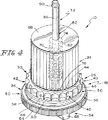
図1に図示するように、フィルタモジュール10は、パン14内の変速機液16を濾過するように変速機パン14に設けられた開口12に取り付けられるように適合されている。車両変速機システム18において、図1に示唆するように、パン14は変速機20から排出される変速機液16を収容しており、ポンプ22はフィルタモジュール10を介して濾過すべき変速機液16を吸い上げて、フィルタモジュール10から排出される濾過された変速機液16を変速機20へと再度循環させる。例えば、図2、図13、及び図15に例示する実施例では、各々のモジュール10、110、及び210は、濾過材24及び、濾過材24と連係する磁性粒子トラップ26を一つ以上含む。磁性粒子トラップ26は、変速機20から排出されてパン14へ入る変速機液16に含まれる近くにある鉄系材料の粒子はなんでも引きつけて保持するように構成されており、そのような鉄系材料の粒子がポンプ22を介して変速機20へ極力再度循環されることがないようにする。
=== Detailed Description of Drawings ===
As illustrated in FIG. 1, the
図2に例えば示すように、フィルタモジュール10は流入流体25から濾過すべき変速機液を収容して、濾過された変速機液を流体出口28に排出するのに適している。フィルタモジュール10は、濾過材24と、濾過材24の下にある磁性粒子トラップ基部30と、濾過材24及び磁性粒子トラップ基部30で濾過した変速機液を流体出口28へと案内する排出導管32とを備えている。フィルタモジュール10はフィルタ取付台36と結合するようになっているコネクタ34を更に備え、このフィルタ取付台36は例えば変速機パン14に設けられている開口12と連係している。コネクタ34はパン14と結合して、濾過材24と磁性粒子トラップ基部30とを支持して、濾過材24と基部30とをパン14内の変速機液16に暴露して、また濾過材24と流体出口28との間を連通させている排出導管32を支持する。作動中には、磁性粒子トラップ基部30は、流入流体26からフィルタモジュール10に供給される変速機液中に保持されている近くの鉄系材料粒子を引きつけて捕捉するように構成されており、それでそのような粒子が排出導管32を介して流体出口28に排出されることを最小にする。
As shown, for example, in FIG. 2, the
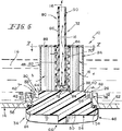
図3から図6にはフィルタモジュール10の一実施例が例示される。特に図3に示すように、濾過材24はフィルタ材料で作られたスリーブを備え、磁性粒子トラップ基部30はフィルタスリーブ24を支持するようにその下にある板38及び板38の周辺縁44に配置される一連の鉄系材料粒子収容切欠き42を含んで形成されたトラップ部40を備える。また例えば図3及び図6に示すように、コネクタ34の板38、トラップ部40、及び本体部分50は磁性プラスチック材料で形成されていて、それらは結合されて一体構造の部材46を形成する。なんらかの適切な成分と磁化材料とを混ぜ合わせて、変速機液16中に混入した鉄系材料粒子48(図6に示す)を引きつけて保持する磁性プラスチック材料を作ることは本開示の範囲内である。
3 to 6 illustrate one embodiment of the
図3に特に示すように、コネクタ34は、軸方向上部分52及び軸方向下部分54を含む本体50を備える。コネクタ34は図3に示すOリング56も備えており、Oリングは図4及び図6に示すように本体50の周りに配設されうるようなサイズとされている。本体50は磁性プラスチック材料で形成されて、磁性粒子トラップ基部30と結合されて前述の一体構造の部材46を提供する。
As specifically shown in FIG. 3, the
図3及び図6に示すように、コネクタ34の本体50の軸方向上部分52は、外面結合部分58(例えば、ねじ)及び外面結合部分58の上の軸方向上向きの表面60を含む。図6に示すように、外面結合部分58は、変速機パン14の床部62に形成される開口12に設けられた結合フィルタ取付台カラー36と係合するのに適している。ねじ或いはなんらかの適切なシステムを使用して、コネクタ34の本体50を変速機パン14と連係しているフィルタ取付台36に結合することは、本開示の範囲内である。
As shown in FIGS. 3 and 6, the axially
例えば図3及び図5に示すように、コネクタ34の本体50の軸方向下部分54は、放射状に外側に延在する環状フランジ64及びハンドル66を含む。図6に特に示すように、Oリングシール56は本体50の周りに環状フランジ64に対向するように配置される。図5に図示する実施例では、ハンドル66は“プラス記号”と類似する形状を有する。図示するように環状フランジ64の外縁には鋸歯状の凹凸が設けられ、コネクタ34のその部分をユーザーが掴むことを可能にして、フィルタモジュール10を“手でひねって(ハンドトルクで)”パン14の開口12に取り付けることを容易にする。
For example, as shown in FIGS. 3 and 5, the axially
図3から図6に示すように、磁性粒子トラップ基部30のトラップ部40は、一連の“扇形(scallop-shaped)”の、放射状に外側へ開いている、凹面の、湾曲している外面側壁68を含み、外面側壁68はトラップ部40の外面周辺部の周囲に互いに間隔をおいて配置される。それぞれの側壁68は軸方向上向きの表面60の隣接部分と共に、鉄系材料粒子収容切欠き42を一つ形成する。このように、軸方向上向き表面60はトラップ部40の“扇形”周辺部68の周りに隣接するように位置づけられて、それぞれの粒子収容切欠き42の床部を形成する。本開示の範囲内で、各側壁68と連係する切欠き床部(notch floor)の大きさや形状を変えることができる。
As shown in FIGS. 3-6, the
磁性プラスチック材料を使用して一体構造の部材46を成形すると、それぞれの粒子収容切欠き42と連係する側壁68及び床部60が磁性材料を構成して、変速機液16中に保持されていて切欠き42の近くにあるあらゆる鉄系材料粒子48(図6を参照)を切欠き42内に引きつけて捕捉する方法が提供される。本開示の範囲内に、側壁68及び床部60の一方或いは両方に磁性コーティング(図示しない)を施すか、或いは側壁及び底の一方或いは両方を磁性材料で形成することが含まれる。
When the integrally structured
図3には排出導管32の一実施例が示される。排出導管32は孔開き外側スリーブ70を含み、孔開き外側スリーブ70は濾過材24に設けられた内部部分72へ延長する寸法であり、軸方向上端74及び下端76を含むように形成される。軸方向上端74は、末端開口78を含むように形成される。排出管80は、末端開口78を通って延長して、孔開き外側スリーブ70の内部部分84内に置かれる軸方向下端82と内部部分84外に置かれる軸方向上端86とを含む。例示の実施例では、孔開き外側スリーブ70と排出管80とはプラスチック材料で形成されて、それらは結合されて一体構造の排出導管32を形成する。本開示の範囲内には、孔開き外側スリーブ70の中又は上に、あるいはそれらの両方に磁性材料を設けて、濾過材24の内部部分72に到達したおそれのある、近くにある鉄系材料粒子48はなんでも引きつけて捕捉する方法を提供することが含まれる。
FIG. 3 shows an embodiment of the
図3、図4、及び図6に示すように、例示する実施例では、フィルタモジュール10は上端板88とOリングシール90とを更に備える。上端板88は中央開口92を含んで形成され、排出管80の軸方向上部86がその開口92を介して延在する。フィルタモジュール10を構成する部品を組み立てると、上端板88は孔開き外側スリーブ70の軸方向上端74上に来るように設置される。Oリングシール90は軸方向上部86の軸方向外側端の近くに形成される環状溝94に嵌合するような寸法であり、フィルタモジュール10がパン14内に取り付けられると変速機パン14や別の構造と封止状態で接触する。本開示の範囲内で、濾過材24の内部部分から濾過された流体を変速機パン14外の遠隔の場所へ排出するための別の適切な方法が提供される。
As shown in FIGS. 3, 4, and 6, in the illustrated embodiment, the
例えば図6に示すように、フィルタモジュール10が組み立てられると、孔開き外側スリーブ70の軸方向下端76は磁性粒子トラップ基部30の板38と結合して、排出管80の軸方向下端82は内部部分84内に孔開き外側スリーブ70の軸方向下端76の上にそこから離隔するように配置される。そのため、濾過材24の内部部分72にある変速機液16は、最初外側スリーブ70の穿孔を通り、外側スリーブ70の内部部分84へ通るように強制されて、その後軸方向下端76を通り排出管80へ入り、そのようにして濾過された変速機液16は排出導管32を介してフィルタモジュール10から吸い出される。孔開き外側スリーブ70の軸方向下端76は磁性粒子トラップ基部30に隣接して位置づけられており、軸方向下端76が磁性粒子トラップ基部30まで或いはその近くまで延長する。
For example, as shown in FIG. 6, when the
フィルタモジュール部品を組み立てる一方法では、濾過材24の下端を板38に結合して濾過材24の上端を上端板88に結合する。濾過材24を板38、88に結合するには、赤外熱板接合(infrared, hot plate bonding)、或いは他の適切な結合処理を使用してもよい。濾過材24の下端が板38に結合される前に、排出導管32を濾過材24の内部部分72を通して、上端板88に形成された中央開口92を通して、“底から”(from the bottom)通すことができる。排出導管32は、スピン溶接或いは他の適切な技術で上端板88に結合できる。適当な設計で、これらの部品は結合される個別の部品ではなく、一つ或いは一つ以上の装置に成形してもよい。
In one method of assembling the filter module components, the lower end of the
図2に示すフィルタモジュール10の別の実施例は、図8及び図9にフィルタモジュール10’として例示される。この実施例では、コネクタは変速機パン14の底壁62に形成された開口内に完全に嵌合するように改良されて、パン14の底部外面と“面一”になるようにする。この構造は図3から図7のフィルタモジュール10と別の点で類似しており、コネクタ内に形成された内部部分に引っ込んであるハンドル66’を提供する。
Another embodiment of the
コネクタ34’は本体50’とOリングシール56とを含む。本体50’は、軸方向上向き表面60及び外部結合部分58(例えば、ねじ)を設けた軸方向上部を有する円筒状スリーブ51を含む。円筒状スリーブ51は、内部部分53と放射状に外側に延長する環状フランジ64とを設ける軸方向下部を更に含む。ハンドル66’は円筒状スリーブ51の内部部分53に配置されて、軸方向下向き面55に取り付けられる。
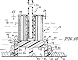
図2に示すフィルタモジュール10の別の実施例は、図10〜図12にフィルタモジュール10’’として例示される。この実施例では、磁性粒子トラップ基部40’は、その周辺部の円周に間隔を置いて設けられた一連の粒子収容くぼみ(particle-receiving wells)41(例えば図8及び図9に示す切欠き42とは異なる)を含んで形成される。それぞれのくぼみ41は、湾曲した外側壁43と、間隔を置いてある一対の放射状に延在する側壁45と、軸方向上向き表面60によって規定される床部とによって画定される。くぼみ41は、例えば図10及び図11に示すように、中に鉄系材料粒子を収容するような大きさを有する。全ての他の点においては、フィルタモジュール10’’はフィルタモジュール10’と同様である。
Another embodiment of the
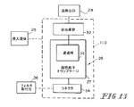
図1に示すフィルタモジュール型式の別の実施例は、図13にフィルタモジュール110として図示される。この実施例では、磁性粒子トラップ26は、濾過材24の下にある磁性粒子トラップ基部30ではなく、濾過材24の周りにある磁性粒子トラップケージ27で規定される。そのようなケージ27の一例を図14に示す。その例示では、ケージ27は二つの半円筒状孔開きシェル半体27a、27bを備えており、それらは結合することができて上端板88とコネクタ34’’との間に設置される孔開きスリーブを供する。それぞれの半体27a、27bは、変速機液が通過して中に収められている濾過材24に到達することができるような開口28を含んで形成されている。ケージ27は磁性プラスチック材料で形成され、ケージ又は開口29あるいはその双方の内部に鉄系材料粒子48を引きつけて保持する。本開示の範囲内には、円筒状或いは他の適切な形状を有する一体構造の孔開きケージを設けることが含まれる。
Another embodiment of the filter module type shown in FIG. 1 is illustrated as
図1に示す型のフィルタモジュールのさらに別の実施例が図15に図示される。二つの磁性粒子トラップ26がフィルタモジュール210に含まれる。磁性粒子トラップ27は一方のトラップ26として機能して、磁性粒子トラップ基部30はもう一方のトラップ26として機能する。
A further embodiment of a filter module of the type shown in FIG. 1 is illustrated in FIG. Two magnetic particle traps 26 are included in the
それぞれの磁性粒子フィルタトラップ26は、変速機液中に含まれる鉄系材料の粒子を捕捉するのを補助すべく磁化されるように混合されたプラスチック複合材を使用して形成される。フィルタモジュールには、磁気吸引力で捕捉した粒子を閉じこめることができる溝或いは穴が組み込まれる。フィルタ全体と、コネクタ栓と、排出配管とを統合することで、部品の数を可及的に減らすことができる。この統合によって、生産段階で簡単な処理が可能になり、フィルタモジュールにねじ及びシールを含めることで、フィルタモジュールを変速機パンに対して簡単にかつ高信頼性でもって取り付け及び取り外しが可能となる。
Each magnetic
Claims (10)
濾過材と、
前記濾過材と連係しており、前記濾過材の近くの鉄系材料の粒子を引きつけるべく磁化されている磁性粒子トラップと、
前記濾過材及び前記磁性粒子トラップの下に配置されているコネクタであって、前記変速機パンと結合して該コネクタの上に支持される前記濾過材及び前記磁性粒子トラップを、前記変速機パンの内部部分に存在する変速機液及びその変速機液中のあらゆる鉄系材料の粒子に暴露するように適合されているコネクタと、
前記濾過材内に延長するように配置され、前記濾過材及び前記磁性粒子トラップによって濾過された変速機液を遠隔の流体出力先へ案内する排出導管と
を備える。 A transmission fluid filter assembly for filtering transmission fluid in a transmission pan, the filter assembly comprising:
A filter medium;
A magnetic particle trap that is linked to the filter media and is magnetized to attract particles of ferrous material near the filter media;
A connector disposed under the filter medium and the magnetic particle trap, wherein the filter medium and the magnetic particle trap supported on the connector coupled to the transmission pan are connected to the transmission pan. A connector adapted to be exposed to transmission fluid present in the interior portion of the motor and any ferrous material particles in the transmission fluid;
A discharge conduit arranged to extend into the filter medium and guiding the transmission fluid filtered by the filter medium and the magnetic particle trap to a remote fluid output destination.
請求項1に記載のフィルタアセンブリ。 The magnetic particle trap is disposed so as to hang from the axial upper surface facing the filter medium and the axial upper surface, and defines a series of particle-containing notches around the outer periphery of the magnetic particle trap. Including a peripheral side edge to be formed,
The filter assembly according to claim 1.
請求項2に記載のフィルタアセンブリ。 The connector includes a body provided with a male thread adapted to engage a threaded collar provided with an opening in the transmission pan, and a radially outwardly extending annular flange coupled to the body. And an O-ring seal disposed around the body so as to face the annular flange,
The filter assembly according to claim 2.
請求項2に記載のフィルタアセンブリ。 The connector is adjacent to the body around the peripheral edge on the coupling portion and a body provided with an outer coupling portion adapted to engage with a coupling collar providing an opening in the transmission pan. An axially upward surface provided with a floor in each particle-containing notch, an annular flange extending radially outwardly coupled to the body, a handle associated with the annular flange, and An O-ring seal disposed around the body to face the annular flange,
The filter assembly according to claim 2.
請求項1に記載のフィルタアセンブリ。 A one-piece member made of magnetic plastic material is configured to define the magnetic particle trap and the connector;
The filter assembly according to claim 1.
前記磁性粒子トラップに隣接して配置された軸方向下端部と、末端開口を含んで形成された反対側の軸方向上端部とを有する孔開き外側スリーブと、
前記末端開口を通って延長しており、前記孔開き外側スリーブの内部部分にあって該孔開き外側スリーブの軸方向下端の上方にこれと離れた関係にある軸方向下端部と、前記孔開き外側スリーブの内部部分の外にあって前記濾過材とは離れている軸方向上端部とを有する排出管と
を含む、
請求項1に記載のフィルタアセンブリ。 The discharge conduit is
A perforated outer sleeve having an axial lower end disposed adjacent to the magnetic particle trap and an opposite axial upper end formed to include an end opening;
An axial lower end extending through the end opening and in an inner portion of the perforated outer sleeve and spaced apart from an axial lower end of the perforated outer sleeve; and the perforated A discharge pipe having an axial upper end outside the inner portion of the outer sleeve and away from the filter media;
The filter assembly according to claim 1.
前記磁性粒子トラップは、前記フィルタスリーブを下から支持するように配置された板と、前記板の周囲縁の周りに配置される一連の粒子収容切欠きを含んで形成されたトラップ部とを備える、
請求項1に記載のフィルタアセンブリ。 The filter medium comprises a sleeve made of filter material;
The magnetic particle trap includes a plate disposed so as to support the filter sleeve from below, and a trap portion formed including a series of particle-containing notches disposed around a peripheral edge of the plate. ,
The filter assembly according to claim 1.
ハンドルと、
前記変速機パンへの開口を設けるようなねじ付きカラーと係合するようになっている、前記トラップ部及び前記ハンドルの間に位置づけられる雄ねじと
を備える、
請求項7に記載のフィルタアセンブリ。 The connector is
A handle,
An external thread positioned between the trap portion and the handle adapted to engage a threaded collar that provides an opening to the transmission pan.
The filter assembly according to claim 7.
請求項1に記載のフィルタアセンブリ。 The magnetic particle trap includes a cage formed to include an internal portion that houses the filter medium.
The filter assembly according to claim 1.
請求項1に記載のフィルタアセンブリ。 The magnetic particle trap includes (i) a cage formed to include an inner portion that accommodates the filter medium, and (ii) a magnetic particle trap disposed under the filter medium and the magnetic particle cage.
The filter assembly according to claim 1.
Applications Claiming Priority (2)
| Application Number | Priority Date | Filing Date | Title |
|---|---|---|---|
| US09/974,463 US6464863B1 (en) | 2001-10-10 | 2001-10-10 | Transmission fluid filter assembly |
| PCT/US2002/014528 WO2003031017A1 (en) | 2001-10-10 | 2002-05-07 | Transmission fluid filter assembly |
Publications (3)
| Publication Number | Publication Date |
|---|---|
| JP2005504937A JP2005504937A (en) | 2005-02-17 |
| JP2005504937A5 JP2005504937A5 (en) | 2005-11-17 |
| JP3890329B2 true JP3890329B2 (en) | 2007-03-07 |
Family
ID=25522068
Family Applications (1)
| Application Number | Title | Priority Date | Filing Date |
|---|---|---|---|
| JP2003534044A Expired - Fee Related JP3890329B2 (en) | 2001-10-10 | 2002-05-07 | Transmission fluid filter assembly |
Country Status (7)
| Country | Link |
|---|---|
| US (1) | US6464863B1 (en) |
| EP (1) | EP1434639A4 (en) |
| JP (1) | JP3890329B2 (en) |
| BR (1) | BR0206817A (en) |
| CA (1) | CA2440003C (en) |
| MX (1) | MXPA03010719A (en) |
| WO (1) | WO2003031017A1 (en) |
Families Citing this family (24)
| Publication number | Priority date | Publication date | Assignee | Title |
|---|---|---|---|---|
| US7014772B2 (en) * | 2002-03-14 | 2006-03-21 | Spx Corporation | Fibrous filter assembly and method |
| US7056432B2 (en) * | 2003-02-21 | 2006-06-06 | Deere & Company | Tank mounted oil filter assembly |
| US7166210B2 (en) * | 2003-02-21 | 2007-01-23 | Deere & Company | Oil filter cartridge |
| US6869527B2 (en) * | 2003-06-17 | 2005-03-22 | Kuen Hsien Lu | Filter facility having flow facilitating structure |
| JP5192698B2 (en) * | 2004-02-17 | 2013-05-08 | イー・アイ・デュポン・ドウ・ヌムール・アンド・カンパニー | Centrifugal solid-liquid separation facilitated by magnetic field and magnetic field gradient |
| US8075771B2 (en) * | 2005-02-17 | 2011-12-13 | E. I. Du Pont De Nemours And Company | Apparatus for magnetic field gradient enhanced centrifugation |
| US8066877B2 (en) | 2005-02-17 | 2011-11-29 | E. I. Du Pont De Nemours And Company | Apparatus for magnetic field and magnetic gradient enhanced filtration |
| FR2891552B1 (en) * | 2005-10-05 | 2012-11-30 | Agronomique Inst Nat Rech | RECOMBINANT BACULOVIRUS EXPRESSING MULTIPLE GENES HETEROLOGISTS. |
| US8293103B2 (en) * | 2005-12-08 | 2012-10-23 | Donaldson Company, Inc. | Spin-on filter assembly and methods |
| JP4867588B2 (en) * | 2006-11-06 | 2012-02-01 | トヨタ紡織株式会社 | Oil filter for automatic transmission |
| DE102007023641B4 (en) * | 2007-05-22 | 2015-04-02 | Ibs Filtran Kunststoff-/ Metallerzeugnisse Gmbh | Oil filter device |
| GB2463898B (en) * | 2008-09-29 | 2012-08-01 | Gm Global Tech Operations Inc | Oil filter for an automatic transmission |
| KR101366653B1 (en) * | 2012-11-09 | 2014-02-24 | 이원재 | Oil filter |
| DE102013014453A1 (en) * | 2013-08-30 | 2015-03-05 | Rt-Filtertechnik Gmbh | Filter device for fluids |
| DE102014007129A1 (en) * | 2014-05-16 | 2015-11-19 | Audi Ag | Electromagnet for a hydraulic system |
| USD772379S1 (en) * | 2015-01-06 | 2016-11-22 | A. J. Antunes & Co. | Insert for fluid treatment cartridge with fluid treatment cartridge |
| US20170173592A1 (en) * | 2015-12-22 | 2017-06-22 | GM Global Technology Operations LLC | Debris trapping magnet configuration |
| DE102015017023A1 (en) * | 2015-12-31 | 2017-07-06 | Hydac Filtertechnik Gmbh | filter means |
| DE202015009372U1 (en) * | 2015-12-31 | 2017-04-19 | Hydac Filtertechnik Gmbh | Filter device for transmission oil |
| DE102016121863A1 (en) * | 2016-11-15 | 2018-05-17 | Boge Elastmetall Gmbh | Suction oil filter for a transmission or internal combustion engine |
| US10408332B2 (en) * | 2016-11-22 | 2019-09-10 | Ford Global Technologies, Llc | Transmission oil filter with internal magnets |
| JP7162348B2 (en) * | 2018-08-29 | 2022-10-28 | 株式会社前田シェルサービス | Magnetic filter device |
| CN109209555B (en) * | 2018-10-19 | 2020-04-10 | 温州承玥机械设备有限公司 | Oil return filter for marine main engine |
| CN109999995B (en) * | 2019-05-05 | 2020-09-25 | 台州瑞格机电工业有限公司 | Control method for improving wear resistance of gearbox |
Family Cites Families (26)
| Publication number | Priority date | Publication date | Assignee | Title |
|---|---|---|---|---|
| US2435517A (en) * | 1945-12-27 | 1948-02-03 | Seltzer Harry | Magnetic filter plug |
| US3211291A (en) * | 1963-04-10 | 1965-10-12 | Marvin G Teutsch | Combination drain plug and screen |
| US3463729A (en) * | 1967-04-17 | 1969-08-26 | Carmon J Bean | Magnetic filtration of transmission fluid |
| US3784011A (en) * | 1972-04-28 | 1974-01-08 | F P Smith Corp | Automatic transmission fluid filter |
| US4657671A (en) * | 1984-03-19 | 1987-04-14 | Aeroquip Corporation | Liquid filter with chip detecting means |
| US4689144A (en) * | 1984-03-27 | 1987-08-25 | Australian Pacific Marketing Pty. Ltd. | Disposable filter unit for automatic transmission fluid |
| JPS6242713A (en) * | 1985-08-14 | 1987-02-24 | Aisin Warner Ltd | In-line strainer |
| US4995971A (en) | 1989-08-07 | 1991-02-26 | Ford Motor Company | Dual purpose automatic transmission oil pan |
| US5468529A (en) | 1992-08-28 | 1995-11-21 | Korea Institute Of Science And Technology | Magnetic filter material comprising a self-bonding nonwoven fabric of continuous thermoplastic fibers and magnetic particulate within the fibers |
| US5314625A (en) | 1992-12-29 | 1994-05-24 | Michael Farnelli | External oil pan magnet |
| US5389252A (en) | 1993-07-28 | 1995-02-14 | Morrick; Robert A. | Magnetic filter aid |
| WO1995007126A1 (en) | 1993-09-07 | 1995-03-16 | Brunsting William J | Magnetic filter assembly |
| US5423983A (en) | 1994-02-07 | 1995-06-13 | Chiang; Jean | Oil filter with a magnetic unit |
| US5441647A (en) | 1994-02-17 | 1995-08-15 | Wascher; Rick R. | Magnetic device for removing metallic matter from lubricating fluids |
| CA2118446A1 (en) | 1994-10-19 | 1996-04-20 | Leonard Calvert | Magnetic filtration device |
| US5647993A (en) | 1995-08-14 | 1997-07-15 | Karp; David P. | Magnetic filter enhancement apparatus and method |
| US6270667B1 (en) | 1995-12-06 | 2001-08-07 | Koji Nakamura | Oil filter not using filter paper but using permanent magnets |
| US5716517A (en) | 1995-12-29 | 1998-02-10 | Dana Corporation | Filter assembly including a magnetized component |
| US5814211A (en) | 1996-05-23 | 1998-09-29 | Leo; Ano | Reusable spin-on multi system oil filter |
| US5714063A (en) | 1996-05-28 | 1998-02-03 | Brunsting; William J. | Apparatus for the removal of ferrous particles from liquids |
| US5997812A (en) | 1996-06-20 | 1999-12-07 | Coolant Treatment Systems, L.L.C. | Methods and apparatus for the application of combined fields to disinfect fluids |
| US5932096A (en) | 1996-09-18 | 1999-08-03 | Hitachi, Ltd. | Magnetic purifying apparatus for purifying a fluid |
| US5702598A (en) | 1996-09-19 | 1997-12-30 | Lemon; John | Magnetic filter |
| US6139737A (en) | 1998-09-04 | 2000-10-31 | Spx Corporation | Transmission fluid filter having a ferrite-filled nylon magnetic body |
| AU1906300A (en) | 1998-10-26 | 2000-05-15 | Bill Holifield | Magnetic core for an oil filter |
| US6210572B1 (en) | 1999-10-18 | 2001-04-03 | Technology Commercialization Corp. | Filter and method for purifying liquids containing magnetic particles |
-
2001
- 2001-10-10 US US09/974,463 patent/US6464863B1/en not_active Expired - Lifetime
-
2002
- 2002-05-07 MX MXPA03010719A patent/MXPA03010719A/en active IP Right Grant
- 2002-05-07 BR BR0206817-6A patent/BR0206817A/en not_active Application Discontinuation
- 2002-05-07 WO PCT/US2002/014528 patent/WO2003031017A1/en active Application Filing
- 2002-05-07 CA CA002440003A patent/CA2440003C/en not_active Expired - Fee Related
- 2002-05-07 EP EP02734274A patent/EP1434639A4/en not_active Withdrawn
- 2002-05-07 JP JP2003534044A patent/JP3890329B2/en not_active Expired - Fee Related
Also Published As
| Publication number | Publication date |
|---|---|
| EP1434639A1 (en) | 2004-07-07 |
| US6464863B1 (en) | 2002-10-15 |
| CA2440003A1 (en) | 2003-04-17 |
| JP2005504937A (en) | 2005-02-17 |
| EP1434639A4 (en) | 2006-01-11 |
| BR0206817A (en) | 2004-02-03 |
| WO2003031017A1 (en) | 2003-04-17 |
| MXPA03010719A (en) | 2004-07-01 |
| CA2440003C (en) | 2007-01-30 |
Similar Documents
| Publication | Publication Date | Title |
|---|---|---|
| JP3890329B2 (en) | Transmission fluid filter assembly | |
| JP2005504937A5 (en) | ||
| JP6258434B2 (en) | Filter element with air vent conduit | |
| KR200493479Y1 (en) | Filtering Device for Aquarium | |
| JP2003250733A (en) | Grille assembly of cyclone dust collector for vacuum cleaner | |
| US4925466A (en) | Filter cartridge assembly | |
| JP2006242180A (en) | Fluid housing used for fluid containing particulate, transmission system using it, sheet installed in it, and method and system for catching particulate contained in fluid in it | |
| US5441647A (en) | Magnetic device for removing metallic matter from lubricating fluids | |
| EP3058818A1 (en) | Aquarium filter with water stream diversion system and method of use thereof | |
| JPH0732892Y2 (en) | Oil filter | |
| US20030006179A1 (en) | Return-side filter for use in a vehicle transmission | |
| US6632354B2 (en) | Combined oil filter and magnet apparatus | |
| EP1417017A1 (en) | Filtration module including unitary filter cartridge-bowl construction | |
| JP2004538133A (en) | Filter element with drain pipe | |
| JP2009150330A (en) | Oil filter | |
| US20090095669A1 (en) | Filter with inverted threads | |
| US6793812B2 (en) | Fluid filtration assembly combining return-side and supply-side filters for use in a vehicle transmission | |
| US6524476B1 (en) | Oil pan containing a magnetic filter apparatus | |
| JP3848566B2 (en) | Slime removal mechanism | |
| JPH0135210Y2 (en) | ||
| KR20010001217A (en) | The device of a oil filtration | |
| JP2003181232A (en) | Dust collector | |
| GB2395144A (en) | A straining device | |
| JPH05156677A (en) | Force drainage system | |
| JP2574062Y2 (en) | Filter device |
Legal Events
| Date | Code | Title | Description |
|---|---|---|---|
| TRDD | Decision of grant or rejection written | ||
| A01 | Written decision to grant a patent or to grant a registration (utility model) |
Free format text: JAPANESE INTERMEDIATE CODE: A01 Effective date: 20061107 |
|
| A61 | First payment of annual fees (during grant procedure) |
Free format text: JAPANESE INTERMEDIATE CODE: A61 Effective date: 20061204 |
|
| R150 | Certificate of patent or registration of utility model |
Free format text: JAPANESE INTERMEDIATE CODE: R150 |
|
| FPAY | Renewal fee payment (event date is renewal date of database) |
Free format text: PAYMENT UNTIL: 20091208 Year of fee payment: 3 |
|
| S111 | Request for change of ownership or part of ownership |
Free format text: JAPANESE INTERMEDIATE CODE: R313113 |
|
| FPAY | Renewal fee payment (event date is renewal date of database) |
Free format text: PAYMENT UNTIL: 20091208 Year of fee payment: 3 |
|
| R350 | Written notification of registration of transfer |
Free format text: JAPANESE INTERMEDIATE CODE: R350 |
|
| FPAY | Renewal fee payment (event date is renewal date of database) |
Free format text: PAYMENT UNTIL: 20101208 Year of fee payment: 4 |
|
| LAPS | Cancellation because of no payment of annual fees |