JP3889645B2 - Cogeneration system - Google Patents
Cogeneration system Download PDFInfo
- Publication number
- JP3889645B2 JP3889645B2 JP2002085586A JP2002085586A JP3889645B2 JP 3889645 B2 JP3889645 B2 JP 3889645B2 JP 2002085586 A JP2002085586 A JP 2002085586A JP 2002085586 A JP2002085586 A JP 2002085586A JP 3889645 B2 JP3889645 B2 JP 3889645B2
- Authority
- JP
- Japan
- Prior art keywords
- cooling water
- radiator
- combustion engine
- control unit
- internal combustion
- Prior art date
- Legal status (The legal status is an assumption and is not a legal conclusion. Google has not performed a legal analysis and makes no representation as to the accuracy of the status listed.)
- Expired - Fee Related
Links
Images


Classifications
-
- Y—GENERAL TAGGING OF NEW TECHNOLOGICAL DEVELOPMENTS; GENERAL TAGGING OF CROSS-SECTIONAL TECHNOLOGIES SPANNING OVER SEVERAL SECTIONS OF THE IPC; TECHNICAL SUBJECTS COVERED BY FORMER USPC CROSS-REFERENCE ART COLLECTIONS [XRACs] AND DIGESTS
- Y02—TECHNOLOGIES OR APPLICATIONS FOR MITIGATION OR ADAPTATION AGAINST CLIMATE CHANGE
- Y02E—REDUCTION OF GREENHOUSE GAS [GHG] EMISSIONS, RELATED TO ENERGY GENERATION, TRANSMISSION OR DISTRIBUTION
- Y02E20/00—Combustion technologies with mitigation potential
- Y02E20/14—Combined heat and power generation [CHP]
-
- Y—GENERAL TAGGING OF NEW TECHNOLOGICAL DEVELOPMENTS; GENERAL TAGGING OF CROSS-SECTIONAL TECHNOLOGIES SPANNING OVER SEVERAL SECTIONS OF THE IPC; TECHNICAL SUBJECTS COVERED BY FORMER USPC CROSS-REFERENCE ART COLLECTIONS [XRACs] AND DIGESTS
- Y02—TECHNOLOGIES OR APPLICATIONS FOR MITIGATION OR ADAPTATION AGAINST CLIMATE CHANGE
- Y02T—CLIMATE CHANGE MITIGATION TECHNOLOGIES RELATED TO TRANSPORTATION
- Y02T10/00—Road transport of goods or passengers
- Y02T10/10—Internal combustion engine [ICE] based vehicles
- Y02T10/12—Improving ICE efficiencies
Description
【0001】
【発明の属する技術分野】
発電と給湯とを行なうコージェネレーションシステムの構成に関する。
【0002】
【従来の技術】
これまでのコージェネレーションシステムでは、ガスや灯油などの燃料を内燃機関で燃焼させ、この内燃機関の駆動力により発電機を運転し、その発電された電力をパワーコンバータで商用電源の電源周波数に変換し、前記商用電源の位相に同調させて、電力線への電源供給を行なうと共に、前記内燃機関を冷却する冷却水路上に熱回収部を設け、給湯槽への熱回収を行なわせて、湯水を貯留し、給湯をも行なっていた。
【0003】
この内燃機関の冷却水路上には、前記熱回収部のほか、この熱回収部で前記給湯槽への熱回収をし切れ無かった熱を放熱させるための放熱器と、この冷却水路内の冷却水を循環させる冷却水ポンプとが設けられ、前記放熱器は、放熱用送風機が設けられた放熱室へ配設されて冷却され、前記内燃機関や、前記冷却水ポンプは、前記パワーコンバータも含め、前記放熱用送風機とは異なる機械室用送風機が設けらた、機械室へ配設されて冷却されていた。
【0004】
【発明が解決しようとする課題】
しかし、コージェネレーションシステムも家庭向け用などの小型のものを考えた場合、発電量は、数キロワット程度で良いものの、このコージェネレーションシステムでの発電電力量に対する、運転するための消費電力量の占める比率が大きくなるため、このコージェネレーションシステムでの運転に関わる補機点数が多いことは、その消費電力量の増加に繋がることから、最終的な発電効率を低下させてしまう結果となり、また、前記補機点数が多いことは、当然ながらコストもアップしていることを意味している。
【0005】
このため、この小型のコージェネレーションシステムでは、このシステム内で消費してしまう前記消費電力量の低減、および、コストの低減を行なうことが要望されていた。
【0006】
そこで、本発明の目的は、コストも抑えると共に、発電効率を向上させたコージェネレーションシステムを提供することにある。
【0007】
【課題を解決するための手段】
請求項1に記載の発明は、発電機を駆動する内燃機関と、発電電力を供給する制御部と、前記内燃機関の冷却水を冷却する放熱器と、この放熱器へ送風する送風機とを筐体内に内蔵して設けたコージェネレーションシステムにおいて、前記放熱器と、前記制御部とを収納した放熱室を設けて、この放熱室に隣接、かつ、連通して、前記内燃機関、および前記発電機を納めた機械室を設け、前記放熱室へ前記送風機を設けて、前記放熱器と、前記制御部と、前記機械室との冷却を行ない、かつ、前記放熱室と、この放熱室の下方に設けた前記機械室とを仕切る仕切り板に開口部を開口させ、この開口部へ雨水侵入防止用の屋根を設けるとともに、前記機械室の底板へ、通気口を開口させたことを特徴とするものである。
【0008】
請求項2に記載の発明は、請求項1に記載のものにおいて、前記制御部と、前記放熱器とを前記放熱室の対向する面に設けたことを特徴とするものである。
【0009】
請求項3に記載の発明は、請求項1または2に記載のものにおいて、前記制御部の外箱の前面と、裏面にスリット状の開口部を設けて、前記制御部の外箱の内部を通気可能としたことを特徴とするものである。
【0010】
請求項4に記載の発明は、請求項1乃至3のいずれかに記載のものにおいて、前記制御部に温度センサを設け、この温度センサからの温度信号に基づいて、前記送風機の運転を制御したことを特徴とするものである。
【0012】
【発明の実施の形態】
以下、本発明の実施の形態について、図1から図5を用いて説明する。
【0013】
図1は、本発明による電力供給を主体としたコージェネレーションシステムの一部を破断して示した斜視図である。
【0014】
このコージェネレーションシステム100の構成は、機械室1と、蓄熱室2と、放熱室3とに大別されており、機械室1は、このコージェネレーションシステム100の下部右側に位置して、ベース部材60上に取り付けられ、通気口62を設けられた底板61へ、内燃機関10と、この内燃機関10の駆動力で駆動される発電機11とが配設されており、これらの他には、冷却水ポンプ12と、排ガス装置13と、図示しない燃料供給装置とが納められ、外装パネル70と、外装パネル71とにより覆われて設けられている。
【0015】
また、蓄熱室2は、このコージェネレーションシステム100の左側に位置して、ベース部材60上にアングルで固定された、給湯槽17が納められ、外装パネル75と、76と、天面パネル74とにより覆われている。
【0016】
さらに、この機械室1の上部には、鋼材63a〜63c、および、64に支持されて設けられた放熱室3が設けられており、この放熱室3の底面には、ドレンパン65が設けられており、蓄熱室2側の側壁へは、仕切板77が取り付けられている。
【0017】
また、この放熱室3内には、内燃機関10の冷却水を流通させて放熱させる放熱器14と、このコージェネレーションシステム100の制御を行なう制御部や、発電した電力の供給を行なうパワーコンバータなどの制御装置18と、ボックス内温度センサ19とを内蔵した制御ボックス15と、この放熱室3内の空気を大気側へ放出させる送風機16とが納められ、外装パネル72、および、スリット31が設けられた外装パネル73と、排気トップ80、および、吹出しグリル78が取り付けられた吹出し口79を有した天面パネル74とにより覆われている。
【0018】
この放熱器14は、放熱室3の1つ面へ側して配設され、制御ボックス15は、そのケース上の前面にスリット29と、裏面にスリット30とが設けられて、放熱器14と対向した面へ配設され、送風機16は、この放熱室3の天面の前記天面パネル74に設けられた吹出し口79の直下に位置して配設されている。
【0019】
また、この放熱室3の底面となるドレンパン65は、図2に示す様に、両側端部を上方に曲げられた板金66、および、67を、鋼材64上へ間隔を設けて並べ、前記機械室1の天面に開口部が設けられる様に取り付けられており、前記開口部には、この開口部より幅広で、両側端部を下方に曲げられた板金68が、前記開口部との間に通風可能な間隔を持って、この開口部を覆う様に取り付けられ、このドレンパン65の下方に設けられた機械室1内の空気が、この放熱室3へ流通可能とされている。
【0020】
そして、この送風機16が、制御装置18からの指示により、運転を開始すると、図3に示す様に、送風機16が、放熱室3内の空気を大気中へ放出させる様に送風を行なうため、放熱器14では、大気側から放熱室3内へ、この放熱器14を冷却しながら通過して空気が流れ、制御ボックス15では、外装パネル73上に設けられたスリット31より大気側から空気が流入し、制御ボックス15の前面に設けられたスリット29と、裏面に設けられたスリット30とを流通して、この制御ボックス15内を冷却しながら通過して、放熱室3内へ空気が流れ、この放熱室3の下方に位置する機械室1では、ドレンパン65上に設けられた板金66と、板金68との間隔、および、板金67と、板金68との間隔より、機械室1内の空気が、放熱室3へと吸引されるため、機械室1の底板61に設けられた通気口62より、空気が侵入して、内燃機関10や、発電機11などを冷却しながら流通して、放熱室3内へと空気が流れる。
【0021】
この様に、放熱室3内の側面の放熱器14と対向する位置へ制御ボックス15を設け、この制御ボックス15の前面と、裏面とに、空気の流通するスリットを設けることにより、制御ボックス15内に納めたパワーコンバータや、制御部などの制御装置18を、送風機16で冷却することが可能となる。
【0022】
さらに、機械室1をこの放熱室3に隣接して設け、放熱室3と、機械室1とを連通して設けることにより、前記送風機16で、この機械室1の冷却までもが可能となる。
【0023】
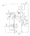
また、このコージェネレーションシステム100を図4の様に回路図に示して説明すると、制御装置18へ発電要求内の信号が送られると、この制御装置18より内燃機関10の運転開始の指示が出され、内燃機関10は、燃料供給装置21から供給される燃料と、吸気装置22から吸入される燃焼用空気とを混合器23で混合して吸引し、この内燃機関内部で燃焼させて、排気ガスを排ガス装置13を経由させて、排気トップ80より排出し、前記燃焼により発生した駆動力で、発電機11を運転して発電を行ない、この発電された電力を制御装置18に含まれた前記パワーコンバータで商用電源の電源周波数、および、位相に同調させて、負荷へと供給し、この内燃機関10の運転開始の指示と共に、冷却水ポンプ12へも運転開始の指示が出され、この内燃機関10の冷却水路内に停流した冷却水を循環させる。
【0024】
ここで、この冷却水路上に設けられている三方弁28は、ワックスなどの封入材が封入され、この三方弁28内を流通する前記冷却水の温度により、前記封入材の体積が変化し、自動的に流通先を切替える機械式の弁であり、前記冷却水の温度が、例えば、60℃未満の場合は、矢印a方向を選択し、60℃以上となった場合には、矢印b方向へ切替える弁である。
【0025】
そして、この時、前記冷却水の水温は、まだ低く、前記60℃未満となっているため、内燃機関10から流出した冷却水は、排ガス装置13を経由して、三方弁28を矢印a方向へ進み、冷却水ポンプ12を経由して、内燃機関10へと戻る冷却水路を循環して、この内燃機関10の暖機運転を行うことになり、前記冷却水の温度が、前記60℃以上となると、三方弁28内に封入された前記封入材の体積が変化して、前記冷却水の流通先は、矢印b方向へと切替えられ、内燃機関10から流出した前記冷却水は、排ガス装置13を経由して、三方弁28を矢印b方向へ進み、給湯槽17内に設けられた熱供給管27を流通し、放熱器14を流通して、冷却水ポンプ12を経由し、内燃機関10へと戻る冷却水路を循環して、前記冷却水から、給湯槽17内に貯留された水への熱回収を行なう。
【0026】
また、前記冷却水の温度が、例えば、80℃以上となった場合、給湯槽17への熱回収を行なうにも、給湯可能な温度を超えてしまう温度、かつ、内燃機関10の冷却が十分に行なえない温度として、この冷却水の温度信号を冷却水路上に設けた冷却水温度センサ26で検出し、制御装置18で放熱器14での強制空冷を判断して、送風機16の運転を行なわせ、前記冷却水の温度が上昇することを抑える。
【0027】
ここで、このコージェネレーションシステム100は、上述の様に、発電主体のコージェネレーションシステムであり、給湯要求の有無に関わらず、内燃機関10、および、発電機11は、運転して発電を行ない、制御ボックス15内に納められたパワーコンバータなどの制御装置18は発熱するため、上記説明での前記冷却水の温度が、前記80℃未満となっている状況でも、制御ボックス15内に設けられたボックス内温度センサ19からの温度信号により、制御装置18から送風機16の運転が行なわれる。
【0028】
この時、例えば、前記冷却水の温度が、前記60℃未満の状態であれば、前記冷却水の温度も低く、内燃機関10の暖機運転を行っている最中であるため、放熱器14を流通しない冷却水路上を循環しているため、制御ボックス15内に設けられたボックス内温度センサ19からの温度信号により、制御装置18から送風機16を運転させても、特に問題となることは無い。
【0029】
また、前記冷却水の温度が、前記80℃以上の状態であれば、上記説明の様に、給湯槽17への熱回収を行なうにも、給湯可能な温度を超えてしまう温度であるとともに、前記冷却水が、給湯槽17での熱回収を行なっても前記80℃以上となってしまうことは、給湯槽17内に貯留された水への熱回収が完了されていることを意味し、かつ、内燃機関10の冷却が十分に行なえない温度であり、冷却水温度センサ26からの温度信号としても、送風機16を運転させる必要があることから、制御ボックス15内に設けられたボックス内温度センサ19からの温度信号により、制御装置18から送風機16を運転させても、特に問題となることは無い。
【0030】
しかし、前記冷却水の温度が、前記60℃以上で、前記冷却水から給湯槽17への熱回収が行なわれ、放熱器14での放熱が必要とされる前記80℃未満の温度であるときでは、前記給湯槽17内に貯留された水への前記冷却水からの熱回収が継続されている状態で、前記冷却水の温度としては、送風機16の運転を行う必要は無いが、ボックス内温度センサ19の温度信号により、制御ボックス15内の温度が上昇し、冷却の必要があるとして、制御装置18から送風機16の運転が行なわれてしまうため、送風機16からの送風を受けて、放熱器14での放熱が行なわれて、前記冷却水の温度は下降してしまい、給湯槽17への熱回収効率を低下させてしまうこととなる。
【0031】
このため、図4に示す内燃機関10の暖機運転を行なう冷却水路と、給湯槽17での熱回収、および、放熱器14での放熱を行なう冷却水路とで構成された冷却水路を、図5に示す様に、第2の三方弁32を設けて、内燃機関10の暖機運転を行なう冷却水路と、給湯槽17での熱回収を行なう冷却水路と、給湯槽17での熱回収、および、放熱器14での放熱を行なう冷却水路とに分割することにより、前記冷却水の温度が、放熱器14での放熱を必要とされる前記80℃未満の温度であれば、前記冷却水は、放熱器14を流通しない冷却水路上を循環するため、前記冷却水の無駄な放熱を避けることが可能となる。
【0032】
また、この第2の三方弁32も、これまでの前記三方弁28と同様の前記冷却水の温度による機械式のものであれば、コストアップとはなってしまうが、特に電力を必要としないため、発電効率を低下させることも無く、給湯槽17での熱回収効率を低下させてしまうことも無い。
【0033】
なお、本実施の形態では、放熱室3に設ける送風機16を、放熱室3の天面に設けて説明したが、この送風機16は、放熱室内に配設された放熱器14と、制御ボックス15と、機械室1内との冷却が行なえるものであれば良いため、例えば、外装パネル72を設けた、この放熱室3の側面へ配設し、前記放熱器14や、制御ボックス15などの冷却を行なわせるものとすることも可能である。
【0034】
【発明の効果】
この様に、送風機を備え、内燃機関の冷却水の放熱を行なわせる放熱器を配設した放熱室へ、パワーコンバータなどの制御装置を納めた制御ボックスに通風用のスリットを設けて配設するとともに、前記内燃機関や、発電機を納めた機械室を、この放熱室へ隣接、かつ、連通して設けることにより、前記送風機で、前記放熱器と、前記制御ボックスと、前記機械室との冷却を行なうことが可能となるため、前記機械室への送風を行なう送風機を削減することができ、コストが抑えられるとともに、このコージェネレーションシステム内で消費してしまう電力を低減させられることから、発電効率を向上させることが可能となる。
【図面の簡単な説明】
【図1】本発明によるコージェネレーションシステムの一部を破断して示した図である。
【図2】本コージェネレーションシステムのドレンパン部について示した構成断面図である。
【図3】本コージェネレーションシステム内を冷却する空気の流れを示した図である。
【図4】本コージェネレーションシステムの概略について示した回路図である。
【図5】図4に示す回路図の熱回収効率を改善した冷却水路の回路図である。
【符号の説明】
1 機械室
2 蓄熱室
3 放熱室
10 内燃機関
11 発電機
14 放熱器
15 制御ボックス
16 送風機
18 制御装置
19 ボックス内温度センサ
29 スリット
30 スリット
31 スリット
61 底板
62 通気口
65 ドレンパン
66 板金
67 板金
68 板金
100 コージェネレーションシステム
101 コージェネレーションシステム[0001]
BACKGROUND OF THE INVENTION
The present invention relates to a configuration of a cogeneration system that performs power generation and hot water supply.
[0002]
[Prior art]
In conventional cogeneration systems, fuel such as gas and kerosene is burned in an internal combustion engine, a generator is driven by the driving force of this internal combustion engine, and the generated power is converted to the power supply frequency of commercial power by a power converter. In addition to supplying power to the power line in synchronization with the phase of the commercial power source, a heat recovery unit is provided on the cooling water passage for cooling the internal combustion engine, and heat recovery to the hot water supply tank is performed to supply hot water. It was stored and hot water was also supplied.
[0003]
On the cooling water channel of the internal combustion engine, in addition to the heat recovery unit, a heat radiator for dissipating heat that has not been fully recovered in the hot water tank by the heat recovery unit, and a cooling in the cooling water channel A cooling water pump that circulates water, the radiator is disposed and cooled in a heat radiating chamber provided with a heat radiating fan, and the internal combustion engine and the cooling water pump include the power converter. The fan for machine room different from the fan for heat dissipation was provided and cooled in the machine room.
[0004]
[Problems to be solved by the invention]
However, when considering a small cogeneration system for home use, the power generation amount may be several kilowatts. However, the power consumption for operation accounts for the power generation amount of this cogeneration system. Since the ratio increases, the large number of auxiliary machines involved in the operation of this cogeneration system leads to an increase in the power consumption, resulting in a decrease in the final power generation efficiency. A large number of auxiliary machines means that the cost is naturally up.
[0005]
For this reason, in this small-sized cogeneration system, it has been desired to reduce the amount of power consumed and the cost consumed in the system.
[0006]
SUMMARY OF THE INVENTION Accordingly, an object of the present invention is to provide a cogeneration system that suppresses costs and improves power generation efficiency.
[0007]
[Means for Solving the Problems]
The invention according to
[0008]
According to a second aspect of the present invention, in the first aspect of the present invention, the controller and the radiator are provided on opposing surfaces of the heat radiating chamber.
[0009]
The invention according to
[0010]
According to a fourth aspect of the present invention, in the device according to any one of the first to third aspects, a temperature sensor is provided in the control unit, and the operation of the blower is controlled based on a temperature signal from the temperature sensor. It is characterized by this.
[0012]
DETAILED DESCRIPTION OF THE INVENTION
Hereinafter, embodiments of the present invention will be described with reference to FIGS.
[0013]
FIG. 1 is a perspective view showing a part of a cogeneration system mainly including power supply according to the present invention.
[0014]
The configuration of the
[0015]
The
[0016]
Further, a
[0017]
Further, in the
[0018]
The
[0019]
Further, as shown in FIG. 2, a
[0020]
And when this
[0021]
In this way, the
[0022]
Furthermore, by providing the
[0023]
Further, the
[0024]
Here, the three-
[0025]
At this time, the water temperature of the cooling water is still low and less than 60 ° C., so that the cooling water flowing out from the
[0026]
In addition, when the temperature of the cooling water is, for example, 80 ° C. or higher, the temperature that exceeds the temperature at which hot water can be supplied and the
[0027]
Here, the
[0028]
At this time, for example, if the temperature of the cooling water is less than 60 ° C., the temperature of the cooling water is low and the warm-up operation of the
[0029]
Moreover, if the temperature of the cooling water is in the state of 80 ° C. or higher, as described above, the heat recovery to the
[0030]
However, when the temperature of the cooling water is 60 ° C. or higher, heat recovery from the cooling water to the hot
[0031]
For this reason, a cooling water channel constituted by a cooling water channel for performing the warm-up operation of the
[0032]
Further, if the second three-
[0033]
In the present embodiment, the
[0034]
【The invention's effect】
In this way, a control box containing a control device such as a power converter is provided with a slit for ventilation in a heat dissipating chamber provided with a blower and dissipating heat from the cooling water of the internal combustion engine. In addition, by providing the internal combustion engine and a machine room containing the generator adjacent to and in communication with the heat radiating chamber, the blower can provide the radiator, the control box, and the machine room. Since it is possible to perform cooling, it is possible to reduce the number of blowers that blow air to the machine room, the cost can be reduced, and the power consumed in this cogeneration system can be reduced. It becomes possible to improve the power generation efficiency.
[Brief description of the drawings]
FIG. 1 is a partially cutaway view of a cogeneration system according to the present invention.
FIG. 2 is a structural cross-sectional view showing a drain pan portion of the present cogeneration system.
FIG. 3 is a diagram showing a flow of air for cooling the inside of the cogeneration system.
FIG. 4 is a circuit diagram showing an outline of the present cogeneration system.
FIG. 5 is a circuit diagram of a cooling water channel with improved heat recovery efficiency of the circuit diagram shown in FIG.
[Explanation of symbols]
DESCRIPTION OF
Claims (4)
前記放熱器と、前記制御部とを収納した放熱室を設けて、この放熱室に隣接、かつ、連通して、前記内燃機関、および前記発電機を納めた機械室を設け、前記放熱室へ前記送風機を設けて、前記放熱器と、前記制御部と、前記機械室との冷却を行ない、かつ、
前記放熱室と、この放熱室の下方に設けた前記機械室とを仕切る仕切り板に開口部を開口させ、この開口部へ雨水侵入防止用の屋根を設けるとともに、前記機械室の底板へ、通気口を開口させたことを特徴とするコージェネレーションシステム。An internal combustion engine that drives a generator, a control unit that supplies generated power, a radiator that cools cooling water of the internal combustion engine, and a blower that blows air to the radiator are provided in a housing. In the system,
A heat dissipating chamber containing the heat radiator and the control unit is provided, and a machine room containing the internal combustion engine and the generator is provided adjacent to and in communication with the heat dissipating chamber, and the heat dissipating chamber is provided. Providing the blower, cooling the radiator, the control unit, and the machine room ; and
An opening is opened in a partition plate that partitions the heat radiating chamber and the machine room provided below the heat radiating chamber, a roof for preventing rainwater intrusion is provided in the opening, and ventilation is provided to the bottom plate of the machine room. A cogeneration system with a mouth open .
Priority Applications (1)
| Application Number | Priority Date | Filing Date | Title |
|---|---|---|---|
| JP2002085586A JP3889645B2 (en) | 2002-03-26 | 2002-03-26 | Cogeneration system |
Applications Claiming Priority (1)
| Application Number | Priority Date | Filing Date | Title |
|---|---|---|---|
| JP2002085586A JP3889645B2 (en) | 2002-03-26 | 2002-03-26 | Cogeneration system |
Publications (2)
| Publication Number | Publication Date |
|---|---|
| JP2003278599A JP2003278599A (en) | 2003-10-02 |
| JP3889645B2 true JP3889645B2 (en) | 2007-03-07 |
Family
ID=29232501
Family Applications (1)
| Application Number | Title | Priority Date | Filing Date |
|---|---|---|---|
| JP2002085586A Expired - Fee Related JP3889645B2 (en) | 2002-03-26 | 2002-03-26 | Cogeneration system |
Country Status (1)
| Country | Link |
|---|---|
| JP (1) | JP3889645B2 (en) |
Families Citing this family (5)
| Publication number | Priority date | Publication date | Assignee | Title |
|---|---|---|---|---|
| JP2006009678A (en) * | 2004-06-25 | 2006-01-12 | Aisin Seiki Co Ltd | Co-generation apparatus |
| KR100702039B1 (en) | 2004-12-10 | 2007-03-30 | 엘지전자 주식회사 | Steam supply and power generation system |
| JP4959364B2 (en) * | 2007-02-14 | 2012-06-20 | 三菱重工業株式会社 | Unit base |
| JP6208519B2 (en) * | 2013-10-03 | 2017-10-04 | ダイニチ工業株式会社 | Cogeneration system |
| CN109441610A (en) * | 2018-09-29 | 2019-03-08 | 全椒赛德利机械有限公司 | A kind of automobile engine using new energy resources radiator |
-
2002
- 2002-03-26 JP JP2002085586A patent/JP3889645B2/en not_active Expired - Fee Related
Also Published As
| Publication number | Publication date |
|---|---|
| JP2003278599A (en) | 2003-10-02 |
Similar Documents
| Publication | Publication Date | Title |
|---|---|---|
| US8360014B2 (en) | Engine housing enclosure | |
| KR100702039B1 (en) | Steam supply and power generation system | |
| JP3889645B2 (en) | Cogeneration system | |
| JP5640938B2 (en) | Heat pump water heater outdoor unit | |
| JPH11200951A (en) | Co-generation device | |
| JP6080794B2 (en) | Package storage type engine generator | |
| WO2015146344A1 (en) | Package-storage-type engine power generator | |
| KR100656627B1 (en) | Bus heater system | |
| JP4000108B2 (en) | Co-generation system | |
| JP2000205606A (en) | Steam supply and power generating device | |
| WO2015146342A1 (en) | Package-storage-type engine power generator | |
| JP2003279139A (en) | Cogeneration system | |
| JP2003089315A (en) | Room temperature adjusting device | |
| JPH0612730U (en) | Ventilation system in soundproof cogeneration system | |
| CN111839255B (en) | Air guide structure and baking cooking device with same | |
| JP2558520Y2 (en) | Fan control unit for cogeneration system | |
| CN217619544U (en) | Brushless motor controller and wall polisher | |
| JP7460960B2 (en) | Cooling structure for power generating unit of range extender vehicle | |
| JP6242992B2 (en) | Package storage type engine generator | |
| JPH05340304A (en) | Electrothermal combination supply equipment | |
| JP3803578B2 (en) | Engine working machine | |
| JP3845306B2 (en) | Engine working machine | |
| JP3237265B2 (en) | Cold storage | |
| JP2004116308A (en) | Power generation device | |
| JP4024099B2 (en) | Grid-connected power generator |
Legal Events
| Date | Code | Title | Description |
|---|---|---|---|
| A621 | Written request for application examination |
Free format text: JAPANESE INTERMEDIATE CODE: A621 Effective date: 20041104 |
|
| A977 | Report on retrieval |
Free format text: JAPANESE INTERMEDIATE CODE: A971007 Effective date: 20060731 |
|
| A131 | Notification of reasons for refusal |
Free format text: JAPANESE INTERMEDIATE CODE: A131 Effective date: 20060808 |
|
| A521 | Written amendment |
Free format text: JAPANESE INTERMEDIATE CODE: A523 Effective date: 20060906 |
|
| TRDD | Decision of grant or rejection written | ||
| A01 | Written decision to grant a patent or to grant a registration (utility model) |
Free format text: JAPANESE INTERMEDIATE CODE: A01 Effective date: 20061128 |
|
| A61 | First payment of annual fees (during grant procedure) |
Free format text: JAPANESE INTERMEDIATE CODE: A61 Effective date: 20061130 |
|
| FPAY | Renewal fee payment (event date is renewal date of database) |
Free format text: PAYMENT UNTIL: 20101208 Year of fee payment: 4 |
|
| LAPS | Cancellation because of no payment of annual fees |