JP3889005B2 - Communication device and transceiver - Google Patents
Communication device and transceiver Download PDFInfo
- Publication number
- JP3889005B2 JP3889005B2 JP2004041597A JP2004041597A JP3889005B2 JP 3889005 B2 JP3889005 B2 JP 3889005B2 JP 2004041597 A JP2004041597 A JP 2004041597A JP 2004041597 A JP2004041597 A JP 2004041597A JP 3889005 B2 JP3889005 B2 JP 3889005B2
- Authority
- JP
- Japan
- Prior art keywords
- axis
- lens
- light
- light sources
- transceiver
- Prior art date
- Legal status (The legal status is an assumption and is not a legal conclusion. Google has not performed a legal analysis and makes no representation as to the accuracy of the status listed.)
- Expired - Fee Related
Links
Images


Classifications
-
- H—ELECTRICITY
- H01—ELECTRIC ELEMENTS
- H01L—SEMICONDUCTOR DEVICES NOT COVERED BY CLASS H10
- H01L25/00—Assemblies consisting of a plurality of individual semiconductor or other solid state devices ; Multistep manufacturing processes thereof
- H01L25/03—Assemblies consisting of a plurality of individual semiconductor or other solid state devices ; Multistep manufacturing processes thereof all the devices being of a type provided for in the same subgroup of groups H01L27/00 - H01L33/00, or in a single subclass of H10K, H10N, e.g. assemblies of rectifier diodes
- H01L25/04—Assemblies consisting of a plurality of individual semiconductor or other solid state devices ; Multistep manufacturing processes thereof all the devices being of a type provided for in the same subgroup of groups H01L27/00 - H01L33/00, or in a single subclass of H10K, H10N, e.g. assemblies of rectifier diodes the devices not having separate containers
- H01L25/075—Assemblies consisting of a plurality of individual semiconductor or other solid state devices ; Multistep manufacturing processes thereof all the devices being of a type provided for in the same subgroup of groups H01L27/00 - H01L33/00, or in a single subclass of H10K, H10N, e.g. assemblies of rectifier diodes the devices not having separate containers the devices being of a type provided for in group H01L33/00
- H01L25/0753—Assemblies consisting of a plurality of individual semiconductor or other solid state devices ; Multistep manufacturing processes thereof all the devices being of a type provided for in the same subgroup of groups H01L27/00 - H01L33/00, or in a single subclass of H10K, H10N, e.g. assemblies of rectifier diodes the devices not having separate containers the devices being of a type provided for in group H01L33/00 the devices being arranged next to each other
-
- H—ELECTRICITY
- H01—ELECTRIC ELEMENTS
- H01L—SEMICONDUCTOR DEVICES NOT COVERED BY CLASS H10
- H01L2924/00—Indexing scheme for arrangements or methods for connecting or disconnecting semiconductor or solid-state bodies as covered by H01L24/00
- H01L2924/0001—Technical content checked by a classifier
- H01L2924/0002—Not covered by any one of groups H01L24/00, H01L24/00 and H01L2224/00
-
- H—ELECTRICITY
- H01—ELECTRIC ELEMENTS
- H01L—SEMICONDUCTOR DEVICES NOT COVERED BY CLASS H10
- H01L33/00—Semiconductor devices with at least one potential-jump barrier or surface barrier specially adapted for light emission; Processes or apparatus specially adapted for the manufacture or treatment thereof or of parts thereof; Details thereof
- H01L33/48—Semiconductor devices with at least one potential-jump barrier or surface barrier specially adapted for light emission; Processes or apparatus specially adapted for the manufacture or treatment thereof or of parts thereof; Details thereof characterised by the semiconductor body packages
- H01L33/52—Encapsulations
- H01L33/54—Encapsulations having a particular shape
Landscapes
- Engineering & Computer Science (AREA)
- Power Engineering (AREA)
- Microelectronics & Electronic Packaging (AREA)
- Physics & Mathematics (AREA)
- Condensed Matter Physics & Semiconductors (AREA)
- General Physics & Mathematics (AREA)
- Computer Hardware Design (AREA)
- Optical Communication System (AREA)
- Led Device Packages (AREA)
Description
本発明の実施形態はトランシーバの分野に関する。具体的には、本発明の実施形態は単一レンズの下に多数の光源を有する通信装置に関する。 Embodiments of the invention relate to the field of transceivers. Specifically, embodiments of the present invention relate to communication devices having multiple light sources under a single lens.
電子機器間でデータを共有する従来の方法の1つは、発光ダイオード(LED)と光検出装置を使用する方法である。たとえば、携帯端末、携帯電話、ラップトップ型コンピュータなどの装置は、各々がLEDと光検出装置を伴うトランシーバを有していれば情報を交換することができる。 One conventional method of sharing data between electronic devices is to use a light emitting diode (LED) and a light detection device. For example, devices such as mobile terminals, mobile phones, and laptop computers can exchange information if each has a transceiver with an LED and a light detection device.
従来のトランシーバは内部に、受信器回路、送信器回路、信号プロセッサ回路を有する。トランシーバは外面の1つに、受信用の光検出装置とレンズ下の送信用LEDとを有する。図1は、従来技術における球面レンズ下のLEDの光強度分布(プロファイル)をシミュレーションした結果を例示するグラフ100である。グラフ100はレンズの水平軸に沿って測定した光の水平角光強度分布カーブ(HAカーブ)102と、レンズの垂直軸に沿って測定した光の垂直角光強度分布カーブ(VAカーブ)104とを示す。HAカーブ102とVAカーブ104は、レンズか任意の距離における−90度から90度の範囲の光強度分布を示す。ゼロ(0)度は、レンズからまっすぐ出てレンズの中心軸を貫通する線を指す。図1では、HAカーブ102とVAカーブ104の両方が、中心軸(0度)でピークになっていることを示す。さらに、各カーブの半強度ポイントは中心軸から15度以上の角度になる。したがって、この装置は、側面が中心軸から15度の角度で延びる円錐形上で良好な強度を提供する。
A conventional transceiver internally includes a receiver circuit, a transmitter circuit, and a signal processor circuit. The transceiver has, on one of its outer surfaces, a light detection device for reception and a transmission LED under the lens. FIG. 1 is a
しかし、単一のLEDが搬送できる情報より多くの情報を送信するニーズがある。従来技術において2つの異なるLEDをトランシーバの同じ外面上に配置する方法がある。このような従来技術の1つでは、追加のレンズをトランシーバ上に配置して追加のLEDに対応させる。この解決法により、図1に描かれたような、良好な光強度分布が得られる。しかし、トランシーバを使用する装置はしばしば非常に小さいため、トランシーバ上の面積は非常に限定されており、第2のLEDのために外面上に別のレンズを追加するという解決法は望ましくない。第2の従来技術の方法では、2つのLEDを単一の球面レンズ下に装着する。しかしこれによって望ましくない光強度分布が生じる結果となる。図2Aは、単一の球面レンズ215下にその垂直軸(軸は図示せず)に沿って装着された2つのLED210aと210bと、その結果得られる光強度分布220を示す。LED210a、210bの各々からの光は中心軸に対して非対称であり、中心軸240からかなり離れた角度でピークになる。たとえば、LED210aでは、光強度は中心軸240から約+15度でピークになり、LED210bでは光強度は中心軸240から約−15度でピークになる。
However, there is a need to transmit more information than can be carried by a single LED. There is a method in the prior art to place two different LEDs on the same outer surface of the transceiver. In one such prior art, an additional lens is placed on the transceiver to accommodate the additional LED. This solution results in a good light intensity distribution as depicted in FIG. However, since devices using transceivers are often very small, the area on the transceiver is very limited and the solution of adding another lens on the outer surface for the second LED is undesirable. In the second prior art method, two LEDs are mounted under a single spherical lens. However, this results in an undesirable light intensity distribution. FIG. 2A shows two
図2Bは、従来技術における図2AのLED210aの光強度を示すグラフ250である。VAカーブ252の光強度は中心軸から15度以上離れてピークになり、中心軸(ゼロ度)では相対的に低い。すなわち、強度はピーク強度の半分より小さい。さらに、LEDが中心軸を中心としていないため、水平カーブ254は中心軸で相対的に弱い光強度を示す。さらに、VAカーブ252は中心軸から−5度以下では強度が非常に低く、HAカーブ254は中心軸の両側で10度以上離れると強度が非常に低いため、中心周辺の円錐形は望ましくない形である。
FIG. 2B is a
標準に適合して正常なデータ転送を行うためには、光強度は中心軸を中心とした円錐形内で規定されたレベルになければならない。必要な光強度は技術に依存する。LEDに供給する電流を増加し、全体的に光強度を増加させることは可能である。しかしこの方法ではかなり余分な電力が消費されてしまう。トランシーバが目的とする装置の多くはバッテリ作動式であり、電力消費は大きな問題である。 In order to achieve normal data transfer in conformity with the standard, the light intensity must be at a defined level within a cone centered on the central axis. The required light intensity depends on the technology. It is possible to increase the current supplied to the LED and increase the light intensity overall. However, this method consumes a considerable amount of power. Many of the devices for which the transceiver is intended are battery operated and power consumption is a major problem.
したがって、少なくとも2つのLEDを有する従来のLED通信装置に伴う1つの問題は、装置の表面上で占有する面積が広すぎるということである。このような装置のもう1つの問題は、レンズの中心軸付近での光強度分布が弱すぎ、データ送信がその影響を受けることである。このような装置のさらに別の問題は、光強度の不足という問題を解決するために、かなりの電力を消費してしまうことである。本発明の目的は、これらの問題を解決した通信装置やトランシーバの提供にある。 Thus, one problem with conventional LED communication devices having at least two LEDs is that the area occupied on the surface of the device is too large. Another problem with such devices is that the light intensity distribution near the central axis of the lens is too weak and data transmission is affected. Yet another problem with such a device is that it consumes considerable power to solve the problem of insufficient light intensity. An object of the present invention is to provide a communication device and a transceiver that solve these problems.
本発明は単一レンズ下に多数の光源を有する光通信装置に関する。本発明の1実施形態では、2つの光源を有する光通信装置を提供する。通信装置は光源に光学的に結合するレンズを有する。レンズは2つの光源からの光をレンズの第1の軸に導くように形成される。通信装置はさらに、レンズの近似中心下に配置された第3の光源を備える。 The present invention relates to an optical communication apparatus having multiple light sources under a single lens. In one embodiment of the present invention, an optical communication device having two light sources is provided. The communication device has a lens that is optically coupled to the light source. The lens is formed to direct light from the two light sources to the first axis of the lens. The communication device further includes a third light source disposed below the approximate center of the lens.
他の実施形態では、第1、第2、第3の光源を備える通信装置を提供する。レンズは第1、第2、第3の光源に光学的に結合する。レンズは、第1の軸に沿って非球面外形と、第1の軸に対して実質的に垂直な第2の軸に沿って実質的な球面外形とを有する。第1と第2の光源は第1の軸に実質的に沿って配置される。 In another embodiment, a communication device including first, second, and third light sources is provided. The lens is optically coupled to the first, second, and third light sources. The lens has an aspheric profile along a first axis and a substantially spherical profile along a second axis that is substantially perpendicular to the first axis. The first and second light sources are disposed substantially along the first axis.
本明細書に組み込まれ本明細書の一部を形成する付随する図面は本発明による実施形態を図示するものであり、この図面は説明と共に本発明の原理を説明するのに役立つ。 The accompanying drawings, which are incorporated in and form a part of this specification, illustrate embodiments according to the present invention, which together with the description serve to explain the principles of the invention.
次の、本発明の実施形態の詳細な説明では、本発明の完全な理解を提供するために、単一レンズの下に多数の光源を有する通信装置に関して多くの具体的な詳細が説明されている。しかし、本発明はこれらの特定の詳細がなくても実施でき、代替の要素や方法を使用しても実行できる。他の例では、本発明の実施形態の態様を不必要にあいまいにすることを避けるために、よく知られた方法、手順、構成要素は記述されていない。 In the following detailed description of embodiments of the present invention, numerous specific details are set forth regarding a communication device having multiple light sources under a single lens in order to provide a thorough understanding of the present invention. Yes. However, the invention may be practiced without these specific details and may be practiced with alternative elements and methods. In other instances, well-known methods, procedures, and components have not been described in order to avoid unnecessarily obscuring aspects of embodiments of the present invention.
本発明による実施形態では、単一レンズ下に多数の光源を有する通信装置が提供される。レンズは、レンズの中心軸に沿った光強度分布が強化されるような形状である。多数の光源に対して単一のレンズを使用することによって、本発明による実施形態は従来の2つのレンズの解決法に比べて占有面積を節約できる。さらに、本発明による実施形態では、レンズの中心軸付近で光強度分布が強化されているため、良好なデータ送信が提供される。さらに、光源に供給する電力を増加させてレンズの中心軸を中心とした円錐形内の弱い光強度分布を補償する必要がないため、電力も節約できる。 In an embodiment according to the present invention, a communication device having multiple light sources under a single lens is provided. The lens is shaped to enhance the light intensity distribution along the central axis of the lens. By using a single lens for multiple light sources, embodiments according to the present invention can save footprint over the conventional two-lens solution. Furthermore, embodiments according to the present invention provide good data transmission because the light intensity distribution is enhanced near the central axis of the lens. Furthermore, since it is not necessary to compensate for the weak light intensity distribution in the conical shape centered on the central axis of the lens by increasing the power supplied to the light source, power can be saved.
本発明による実施形態は、第1の軸に沿って非球面外形を有し、第1の軸に対して実質的に垂直である第2の軸に沿って実質的な球面外形を有するレンズを提供する。このレンズの形状により、完全球面のレンズを使用した場合と比べて、光強度分布が改善される。たとえば、この実施形態では、完全球面のレンズを使用した場合と比べて、より多くの光がレンズの中心軸に向けられるという結果になる。この実施形態については、この実施形態の平面図と側面図である図3Aから図3Cを参照して説明する。 Embodiments in accordance with the present invention include a lens having an aspheric profile along a first axis and a substantially spherical profile along a second axis that is substantially perpendicular to the first axis. provide. This lens shape improves the light intensity distribution as compared to the case of using a perfect spherical lens. For example, this embodiment results in more light being directed to the central axis of the lens compared to using a perfectly spherical lens. This embodiment will be described with reference to FIGS. 3A to 3C which are a plan view and a side view of this embodiment.
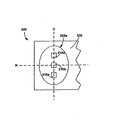
図3Aは、通信装置300の平面図であり、レンズ325aの非球面外形を示す。参考のために、水平軸(H)と垂直軸(V)を示す。次に説明する図4Aから図4Cは、紙面からそれらの軸を上にずらして形成される平面内で、レンズ325aから任意の距離における−90度から90度の範囲にわたる光強度分布を示す。垂直軸に沿って並んだ3つの光源310がある。1実施形態では、光源310は発光ダイオード(LED)を備える。しかし本発明は他の光源での動作にも適している。本発明の説明において、光源という用語は任意の電磁放射を意味し、可視光に限定しないことが意図されている。図3Aの実施形態では、2つの外側LED310aを共に使用して同じ信号を送信する。1実施形態では、2つの外側LED310aは、実質的に同じ波長で放射するように動作可能である。本出願の目的のために、「実質的に同じ波長」とは次のように定義される。標準化機関によれば、波長は所与のタイプの信号に割り当てられる。たとえば、第1の波長はデータ信号に割り当てられ、第2の波長は遠隔制御信号に割り当てられる。2つの外側のLED310aから別々に送信される波長同士が充分近接しており、光検出装置などが別々のLED310aからの信号を単一の送信として正常に受信し復号化できる。
FIG. 3A is a plan view of the
図3Bは、水平軸(水平軸は図3Bに向かい図3Bを突き抜けて伸びる)に沿って見た側面図を示す。3つのLED310は垂直軸に沿って配置される。レンズ325aはこの視点からは非球面外形を有する。図4Aから図4Bから分かるように、非球面外形は、中央のLED310bの光強度分布を実質的に損なうことなく、2つの外側LED310aの光強度分布を改善する。参考のために、図3Bはゼロ(0)度軸を示し、これはレンズ325aの中心軸とも呼ばれる。
FIG. 3B shows a side view as viewed along the horizontal axis (the horizontal axis extends toward FIG. 3B and extends through FIG. 3B). Three LEDs 310 are arranged along the vertical axis. The
図3Cは、垂直軸の方向から見た側面図を示す(垂直軸は図3Cに向かい図3Cを突き抜けて伸びる)。レンズ325aは、この視点からは実質的に球面外形を有する。参考のために、図3Cは図3Bにも示されたゼロ度の軸を示す。
FIG. 3C shows a side view from the direction of the vertical axis (the vertical axis extends towards FIG. 3C and through FIG. 3C). The
1実施形態では、2つの外側LED310aは第1の波長で送信し、一致して動作するように設計される。たとえば、両方の外側LED310aを使用して同じ信号を送信する。中央LED310bは第2の波長で送信し、他の2つのLED310aからは独立して動作する。たとえば、2つの外側LED310aは940nmで動作し、遠隔制御のために使用する。中央LED310bは875nmで動作し、データ転送のために使用される。しかし、中央LED310bを遠隔制御に使用し、外側LED310aをデータ転送のために使用してもよい。さらに、外側LED310aまたは中央LED310bに関して異なる波長を使用してもよい。従来技術の図2Aから図2Bに示された従来技術の解決法とは異なり、2つの外側LED310aを使用して同じ信号を送信することによって、対称な光強度分布が生成される。
In one embodiment, the two
2つのLED310aからの組み合わされた光強度分布が中心軸に対して実質的に対称になるように、2つのLED310aを中心軸に対して配置する。図4Aは、図3Aから図3Cの2つの外側LED310aに関する光強度グラフ400を示す。第1のカーブ402は水平角(HA)に対する光強度を示し、第2のカーブ404は垂直角(VA)に対する光強度を示し、軸は図3Aに画定された通りである。HAカーブ402は、図3Aの水平軸内で、レンズから任意の距離における光強度分布を−90度から90度の角度範囲にわたって示す。VAカーブ404は、図3Aの垂直軸内で、レンズから任意の距離における光強度分布を−90度から90度の角度範囲にわたって示す。HAカーブ402は中心軸に対して対称であることが分かる。VAカーブ404も中心軸に対して対称であるが、HAカーブ402とは異なる形状を有することが分かる。したがって、互いに関して90度の方向を向き各々が中心軸に対して対称な2つの別々の分布がある。本出願の目的のために、中心軸に対してほぼ対称ということは、互いに対して90度の方向を向き各々が中心軸に対してほぼ対称である2つの分布があることを意味する。「ほぼ対称」という用語は、特定の数字値に限定することを意図するものではない。
The two
図3Aを再び参照すると、2つの外側LED310aは中央LED310から実質的に等距離に配置される。「実質的に等距離」という用語は、光強度分布がトランシーバという目的に適合するように、正確な等距離から幾分離れていることを意味する。
Referring back to FIG. 3A, the two
本実施形態では、対称性はレンズ325aの中心軸に対する対称性である。LED310が送信しているときに、トランシーバ300がその方向に向くように設計されているため、このような対称性が選択される。しかし、本発明は中心軸に対して対称であるプロファイルに限定されない。対称性は任意の軸に対するものであってよい。従来技術の図2Aから図2Bに示された非対称な光強度分布と比べて、本発明の対称なプロファイルは改良となる。
In this embodiment, the symmetry is symmetry with respect to the central axis of the
さらに図3Bを参照すると、レンズ325aは2つのLED310aからの光を中心軸に向ける形状である。従来技術の図2Aに示された完全に球面のレンズを使用した従来の解決法など、光を中心軸に向ける形状になっていないレンズと比べた場合、光強度を中心軸に向けることにより、中心軸を中心とした円錐形内の光強度が高まる。したがって、本発明によるこの実施形態は、改善されたデータ通信を提供し、LED310は従来の解決法より少ない電力で動作できる。第3のLED310bはレンズ325aのほぼ中心の下に位置し、2つの外側LED310aとは異なる信号を送信するために使用される。しかし、第3のLED310bをレンズ325aのほぼ中央の下に配置することは必ずしも必要ではない。
Still referring to FIG. 3B, the
従来の技術と比べて光強度分布が改善されたことを示すために、図4Aに光強度分布のシミュレーション結果を示す。HAカーブ402は、中心軸の20度内の光強度が少なくともピーク信号の半分であることを示す。さらに、従来の一部の解決法とは異なり、HAカーブ402は中心軸に対して対称である。対称な光強度は、一部の従来の技術に伴う非対称な光強度より効率がよい。したがって、本発明による実施形態は、中央の円錐付近の望ましくない低い強度を解決するためにLEDへ供給する電流を増加させる必要性を除去する。HAカーブ402はレンズの中心軸を中心とする単一のピークを有し(たとえばゼロ度の角度に沿っている)、中心軸のどちらの側でも中心軸から30度の間で相対的に低い強度を有する。したがって、光強度は中心軸付近で集中し、望ましい。
In order to show that the light intensity distribution is improved as compared with the prior art, FIG. 4A shows a simulation result of the light intensity distribution. The
図4AのVAカーブ404は、中心軸から−50度から50度の角度の範囲内では光の最大強度の50パーセント以下になることはない。VAカーブ404はまた、中心軸に対して対称になっており望ましい。したがって、光検出装置が最適に並んでいる場合、送信側装置の中心軸が垂直軸に沿って配置された受信側装置の光検出装置の50度内を向いていれば、受信側装置は最大信号の50パーセント以上の信号を受信する。VAカーブ404とHAカーブ402から、中心軸を中心とした円錐形は非常に望ましい光強度を有することが明らかであろう。VAカーブ404は3つのピークを有し、これは、レンズの形状と光源の位置の結果生じたものである。VAカーブ404の1つのピークはレンズの中心軸を中心にしており(たとえばゼロ度の角度に沿っている)、他の2つのピークは中心軸からどちらの側でも約40度から50度の位置でピークとなっている。
The
図4Aの光強度カーブの形状は、図3Aから図3Cのレンズ325aの形状と光源310の位置を確認することによって理解できる。図4AのHAカーブ402は単一のピークを示す。図3Cはレンズ325aが水平軸に沿って実質的に球面の形状を有することを示す。本出願の目的のために、「実質的に球面」とは次のように定義される。1実施形態では、この形状は単一の焦点を有し、この結果単一のピークを有する。しかし図3Bに見られるように、垂直方向ではレンズ325aは非球面である。非球面のレンズ325aは2つの焦点を有する。各LED310aからの光によって2つのピークが生じる。しかし、各LED310aからの1つのピークは組み合わさって図4AのVAカーブ404の中央ピークを形成する。したがって、同時に放射する2つのLED310aから3つのピークを伴うVAカーブ404が生じる。しかし、本発明は、第1の軸の非球面外形を、第1の軸に垂直な第2の軸の球面外形に組み合わせることに限定されない。さらに、レンズは水平軸でも垂直軸でも、任意の数の焦点を有していてもよい。したがって、VAカーブ404とHAカーブ402には任意の数のピークがあってもよい。
The shape of the light intensity curve in FIG. 4A can be understood by confirming the shape of the
図4Bは、図3Aから図3Cの中央LED310bに関する光強度グラフ450を示す。第1のカーブ452は水平角の光強度を示し、第2のカーブ454は垂直角の光強度を示し、軸は図3Aで画定された通りである。どちらのカーブも望ましい結果を示す。すなわち、光強度分布は中心軸に対して対称であり、光強度は両方のカーブ452、454に関して中心軸付近で相対的に高い。したがって、光強度は中心軸を中心とする円錐の中では望ましい強度になることが明らかである。HAカーブ452を参照すると、単一のピークはレンズの中心軸を中心にしており(たとえばゼロ度の角度に沿っている)、中心軸のどちらの側でも30度の位置では相対的に低い。したがって、光強度は中心軸近辺に望ましく集中しており、追加の電流を補償としてLEDに送達する必要がないため、電力が節約できる。さらに、高強度部分が中心軸近傍に寄りすぎることはない。たとえば、中心軸のどちらの側でも中心軸から25度における強度は、中心軸でのピーク強度の約半分である。
FIG. 4B shows a
さらに図4Bを参照すると、図4AのVAカーブ404とは異なり、垂直な光強度カーブ454は2つのピークを有する。この場合中央ピークはないが、中心軸の40度以内での光強度は常に、最大強度の少なくとも50パーセントである。さらに、中心軸のどちらの側でも中心軸から約20度の位置では2つのピークがある。したがって、垂直軸に沿って中心軸の40度以内における光強度は常に最大強度の50パーセントより大きい。
Still referring to FIG. 4B, unlike the
図4Bの光強度カーブの形状は、図3Aから図3Cのレンズ325aの形状と光源の位置を参照すると理解できる。図4BのHAカーブ452は単一のピークを示す。図3Cはレンズ325aが水平方向に球面の形状を有していることを示す。この実施形態では球面の形状は単一の焦点を有し、この結果、ピークは1つとなる。しかし図3Bに見られるように、垂直方向ではレンズ325aは非球面である。この実施形態の非球面のレンズ325aは2つの焦点を有する。単一のLED310bがレンズ325aの中心の下の位置から放射すると、結果としてVAカーブ454に2つのピークが生じる。レンズ352aの形状により2つのピークは中心軸から離れているとはいえ、中心軸に沿った強度は非常に高い。
The shape of the light intensity curve in FIG. 4B can be understood by referring to the shape of the
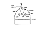
図5Aから図5Cは、レンズ325bが、3つの実質的な球面形状の部分350a、350b、350cから形成される実施形態を示す。図5Aは平面図を示し、3つの球面の部分350a、350b、350cから、全体的には非球面であるが図3Aとは異なる形状ができること示す。この実施形態では、球面部分350a、350b、350cを形成する3つの球面は同じ半径を有し、中心が異なる位置にある。しかし、本発明は各々が同じ半径を有する球面に限定されない。本出願の目的のために、「実質的な球面形状の部分」という用語は、正確な球面形状に限定することを意図するものではない。
5A-5C show an embodiment in which the
参考のために、水平軸(H)と垂直軸(V)を示す。図3Aから図3Cの実施形態に関しては、この実施形態は、垂直方向の軸に沿って並んだ3つのLED310を有する。2つの外側LED310aは実質的に同じ波長で放射するように動作可能である。レンズ325bは2つのLED310aからの光を中心軸に向ける形状である。第3のLED310bはレンズ325bのほぼ中心の下に位置する。しかし必ずしも第3のLED310bをレンズ325bのほぼ中心の下に配置する必要はない。さらに、2つの外側LED310aは垂直方向では軸に沿って配置しなくてもよい。より一般的には、本発明による実施形態では、光強度分布が中心軸に向かうか、および/または、光強度分布が、水平軸または垂直軸のうち少なくとも1つの中心軸に対して対称であるように、適切な形状を有するレンズの下で複数の光源は任意の構成である。
For reference, the horizontal axis (H) and the vertical axis (V) are shown. With respect to the embodiment of FIGS. 3A-3C, this embodiment has three LEDs 310 aligned along a vertical axis. The two
図5Bは、水平軸の方向から見た側面図を示す。3つのLED310は垂直軸に沿って配置される。3つの球面部分350a、350b、350cは、この視点からははっきり認められる。この視点からのレンズ325bの全体形状は非球面である。図6Aから図6Bのためにゼロ(0)度の軸が示されている。
FIG. 5B shows a side view as seen from the direction of the horizontal axis. Three LEDs 310 are arranged along the vertical axis. Three
図5Cは、垂直軸方向から見た側面図を示す。中央の球面部分350bは、外側球面部分350aの一方の上部、背後に見える。この視点からは、外側球面部分350aが中心的であり他の球面部分350bと350cは隠されているため、レンズ325bの全体の形状は実質的に球面である。図6Aから図6Bのために、ゼロ度の軸が示されている。
FIG. 5C shows a side view as seen from the vertical axis direction. The central
図3Aから図3Cの実施形態では、2つの外側LED310aは第1の波長で送信し、一致して動作するように設計されている。たとえば、両方の外側のLED310aを使用して同じ信号を送信する。中央LED310bは第2の波長で送信し、他の2つのLED310aからは独立して動作する。たとえば、2つの外側LED310aは875nmで動作しデータ転送に使用され、中央LED310bは940nmで動作し遠隔制御に使用される。LED310の役割は図3Aから図3Cの実施形態から切り替わっており、LED310の使用、波長、構成が特定の実施例に限定されないことを示す。さらに、異なるLED同士は同じ電力または強度レベルでの動作に制限されない。
In the embodiment of FIGS. 3A-3C, the two
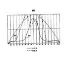
この実施形態に関して従来の技術に比べて光強度分布が改善されたことを示すために、光強度分布のシミュレーション結果を示す。図6Aは、図5Aから図5Cの2つの外側LED310aに関する光強度グラフ600を示す。第1のカーブ602は水平角での光強度を示し、第2のカーブ604は垂直角の光強度を示し、軸は図5Aで画定された通りである。どちらのカーブ602と604も望ましい結果を示す。すなわち、HAカーブ602は光強度が中心軸付近に望ましく集中していることを示す。この結果、追加の電流を補償としてLEDに送達する必要がないため、電力を節約できる。たとえば、HAカーブ602はレンズの中心軸を中心とする(たとえばゼロ度に沿っている)リップルを伴うピークを有し、どちらの側でも中心から40度の位置で相対的に低い。さらに、中心軸に向けられた強度の強い部分は狭すぎることはない。
In order to show that the light intensity distribution is improved as compared to the prior art with respect to this embodiment, a simulation result of the light intensity distribution is shown. FIG. 6A shows a
HAカーブ602に関してと同様に、図6AのVAカーブ604は中心軸に対して対称である。さらに、中心軸から50度内では光強度は常に最大強度の少なくとも50パーセントである。したがって、VAカーブ604とHAカーブ602を検討すると、中心軸を中心とした円錐形は望ましい光強度分布を有することが明らかである。図6AのVAカーブ604は5つのピークを有する。1つのピークはレンズの中心軸を中心としており(たとえばゼロ度の角度に沿っている)、4つはどちらの側でも中心軸から27度と50度の付近でピークとなっている。
As with the
図6Aの光強度カーブ602、604の形状は、図5Aから図5Cのレンズ325bの形状と光源の位置を確認することによって理解できる。この実施形態では、3つの球面部分350a、350b、350cがあり、各々は単一の焦点を有する。図5Aの垂直軸(V)はこれらの3つの球面部分350a、350b、350c全部を通過することに注意されたい。示された構成では、垂直角光強度カーブ(VAカーブ)604の5つのピークは、3つの球面部分350a、350b、350cを介して放射する2つのLED310aの結果生じることが理解されよう。各LED310aは単独で3つのピークを生じるが、これらのうち2つが組み合わさってVAカーブ604の中央のピークを形成する。したがって、中心軸付近の光強度が強化される。図6AのHAカーブ602は、リップルを伴う単一のピークを示す。水平軸(H)は中央の球面部分350bを貫いていることに注意されたい。2つの外側LED310aの各々からの光は、3つの球面部分350a、350b、350cを介して通過しているが、中央球面部分350bがHAカーブ602の形状を生成するのに最も重要である。しかし、外側球面部分350aと350cから生じるHAカーブ604のリップルは、信号の質を低下させるものではない。
The shape of the light intensity curves 602 and 604 in FIG. 6A can be understood by confirming the shape of the
図6Bは、図5Aから図5Cの中央LED310bに関する光強度グラフ650を示す。第1のカーブ652は水平角光強度を示し、第2のカーブ654は垂直角光強度を示し、軸は図5Aで画定された通りである。どちらのカーブも望ましい結果を示す。すなわち、HAカーブ652はレンズの中心軸を中心とした単一ピークを有し(たとえばゼロ度の角度に沿っている)、中心のどちらの側でも30度の位置では相対的に低い。したがって、光強度は中心軸付近に望ましく集中しており、追加の電流を補償としてLEDに送達する必要がないので電力も節約できる。さらに、中心軸近傍の高強部分は狭すぎることはない。たとえば、中心軸の両側の20度における強度は中央のピークに対してかなり大きい。また、従来の解決法とは異なり、光強度は対称である。
FIG. 6B shows a
2つのピークを示す図4BのVAカーブ454とは対称に、VAカーブ654は3つのピークを有する。本実施形態では、中央のピークがあり中心軸上の光強度が実質的である。さらに、中心軸のどちらの側でも2つのピークは中心軸から約25度にある。したがって、光強度は中心軸を中心とする有効な円錐形内でかなりのものである。たとえば垂直角強度は、中心軸から30度内では常に最大強度の少なくとも50パーセントである。HAカーブ652と同様に、VAカーブ654の光強度の分布は中心軸を中心として対称である。
In contrast to the VA curve 454 of FIG. 4B which shows two peaks, the
図6Bの光強度カーブの形状は、図5Aから図5Cのレンズ325bの形状と光源の位置を確認すると理解できる。図5Aから図5Cに示された実施形態は、3つの球面部分350a、350b、350cを有し、各々は単一の焦点を有する。この実施形態では、球面部分350a、350b、350cを形成する球面の中心は垂直軸の異なるポイントに位置する。したがって、中央に配置された1つのLED310bから、垂直軸に3つのピークと水平軸に単一のピークが生じる。しかし、本発明は、異なる数の球面部分を使用した形態にも適しており、この場合、垂直光強度のピークの数も異なる。
The shape of the light intensity curve in FIG. 6B can be understood by confirming the shape of the
本発明は、中心軸付近の光強度が強化された望ましい光強度分布を生じさせるために非球面レンズプロファイルまたは3つの球面部分を使用することに限定されない。本発明の実施形態は他のレンズ形状にも適切である。さらに、中心軸付近の光強度が強化された望ましい光強度分布を作成するために、実施形態によってはレンズの厚さを変える。たとえば、レンズの形状を非球面にしたり多数の球面部分を使用したりする代わりに、レンズの厚さを変えてLEDからの光を中心軸に向けてもよい。 The present invention is not limited to using an aspheric lens profile or three spherical portions to produce a desired light intensity distribution with enhanced light intensity near the central axis. Embodiments of the invention are also suitable for other lens shapes. Furthermore, in order to create a desired light intensity distribution with enhanced light intensity near the central axis, the thickness of the lens is changed in some embodiments. For example, instead of making the lens shape an aspherical surface or using a large number of spherical surface portions, the lens thickness may be changed to direct light from the LED toward the central axis.
本発明を特定の実施形態で説明したが、本発明はこのような実施形態に限定されるものではなく、付随する請求項にしたがって解釈すべきものであることを理解されたい。以下に本発明の実施の参考となる本発明の実施態様のいくつかを例示する。 Although the invention has been described in specific embodiments, it should be understood that the invention is not limited to such embodiments, but is to be construed in accordance with the appended claims. Below, some of the embodiments of the present invention which are references for carrying out the present invention will be exemplified.
(実施態様1):2つの光源と、前記2つの光源と光学的に結合するレンズとを備え、前記レンズは、前記2つの光源からの光を前記レンズの第1の軸に向ける形状である通信装置。 (Embodiment 1): Two light sources and a lens optically coupled to the two light sources, the lens having a shape for directing light from the two light sources toward the first axis of the lens Communication device.
(実施態様2):前記レンズのほぼ中心の下に配置される第3の光源をさらに備える実施態様1に記載の通信装置。
(Embodiment 2): The communication apparatus according to
(実施態様3):前記2つの光源は、前記第3の光源から実質的に等距離に配置されることを特徴とする実施態様2に記載の通信装置。 (Embodiment 3): The communication apparatus according to Embodiment 2, wherein the two light sources are disposed substantially equidistant from the third light source.
(実施態様4):前記2つの光源は、実質的に同じ波長で放射するように動作可能であることを特徴とする実施態様3に記載の通信装置。 (Embodiment 4): The communication apparatus according to Embodiment 3, wherein the two light sources are operable to emit at substantially the same wavelength.
(実施態様5):前記第3の光源は前記2つの光源とは異なる波長で放射するように動作可能であることを特徴とする実施態様4に記載の通信装置。 (Embodiment 5): The communication apparatus according to Embodiment 4, wherein the third light source is operable to emit at a wavelength different from that of the two light sources.
(実施態様6):前記2つの光源は発光ダイオードであることを特徴とする実施態様1に記載の通信装置。
(Embodiment 6): The communication apparatus according to
(実施態様7):前記レンズは複数の実質的に球面の部分を備えることを特徴とする実施態様1に記載の通信装置。
(Embodiment 7): The communication apparatus according to
(実施態様8):前記レンズは3つの実質的に球面の部分を備えることを特徴とする実施態様1に記載の通信装置。
(Embodiment 8): The communication apparatus according to
(実施態様9):前記レンズは前記レンズの第2の軸に沿って非球面外形と、前記第2の軸に対して垂直な前記レンズの第3の軸に沿って実質的に球面外形を有することを特徴とする実施態様1に記載の通信装置。
Embodiment 9: The lens has an aspheric outline along a second axis of the lens and a substantially spherical outline along a third axis of the lens perpendicular to the second axis. The communication apparatus according to
(実施態様10):前記2つの光源は第2の軸に沿った方向を向いていることを特徴とする実施態様9に記載の通信装置。 (Embodiment 10): The communication apparatus according to Embodiment 9, wherein the two light sources are oriented in a direction along the second axis.
(実施態様11):前記レンズは複数の実質的球面部分を備えることを特徴とする実施態様9に記載の通信装置。 (Embodiment 11): The communication apparatus according to Embodiment 9, wherein the lens includes a plurality of substantially spherical portions.
(実施態様12):前記2つの光源からの光を前記第1の軸に向けるように、前記レンズの厚さは前記レンズの表面全体で変わることを特徴とする実施態様1に記載の通信装置。
(Embodiment 12): The communication apparatus according to
(実施態様13):第1と第2の光源と、第3の光源と、前記第1、第2、第3の光源に光学的に結合するレンズであって、前記第1の軸に沿った非球面外形と、前記第1の軸に実質的に垂直な第2の軸に沿った実質的球面外形とを有するレンズとを備え、前記第1と第2の光源は前記第1の軸に実質的に沿って配置される通信装置。 (Embodiment 13): First and second light sources, a third light source, and a lens that optically couples to the first, second, and third light sources, along the first axis A lens having an aspheric outer shape and a substantially spherical outer shape along a second axis substantially perpendicular to the first axis, wherein the first and second light sources are the first axis. Communication device disposed substantially along the line.
(実施態様14):前記第3の光源は前記レンズのほぼ中心の下に配置されることを特徴とする実施態様13に記載の通信装置。 (Embodiment 14): The communication apparatus according to Embodiment 13, wherein the third light source is disposed substantially under the center of the lens.
(実施態様15):前記第1と第2の光源は共に、第1の波長で同じ信号を送信するように放射することを特徴とする実施態様13に記載の通信装置。 (Embodiment 15): The communication apparatus according to Embodiment 13, wherein both the first and second light sources radiate so as to transmit the same signal at the first wavelength.
(実施態様16):前記第3の光源は第2の波長で放射することを特徴とする実施態様15に記載の通信装置。 (Embodiment 16): The communication apparatus according to Embodiment 15, wherein the third light source emits at a second wavelength.
(実施態様17):前記第1と第2の光源は発光ダイオードであることを特徴とする実施態様13に記載の通信装置。 (Embodiment 17): The communication apparatus according to Embodiment 13, wherein the first and second light sources are light emitting diodes.
(実施態様18):前記第3の光源は発光ダイオードであることを特徴とする実施態様17に記載の通信装置。 (Embodiment 18): The communication apparatus according to Embodiment 17, wherein the third light source is a light emitting diode.
(実施態様19):前記レンズは複数の実質的に球面の部分を備えることを特徴とする実施態様13に記載の通信装置。 (Embodiment 19): The communication device according to Embodiment 13, wherein the lens includes a plurality of substantially spherical portions.
(実施態様20):前記レンズは3つの実質的に球面の部分を備えることを特徴とする実施態様13に記載の通信装置。 (Embodiment 20): The communication device according to embodiment 13, wherein the lens comprises three substantially spherical portions.
(実施態様21):前記第1と第2の光源は前記第3の光源から実質的に等距離に配置されることを特徴とする実施態様13に記載の通信装置。 (Embodiment 21): The communication apparatus according to Embodiment 13, wherein the first and second light sources are arranged at substantially the same distance from the third light source.
(実施態様22):前記第1と第2の光源は遠隔制御信号源として動作可能であることを特徴とする実施態様13に記載の通信装置。 (Embodiment 22): The communication apparatus according to embodiment 13, wherein the first and second light sources are operable as a remote control signal source.
(実施態様23):前記第3の光源はデータ信号源として動作可能であることを特徴とする実施態様13に記載の通信装置。 (Embodiment 23): The communication apparatus according to Embodiment 13, wherein the third light source is operable as a data signal source.
(実施態様24):2つの光源と、前記2つの光源に光学的に結合し中心軸を有するレンズとを備え、前記2つの光源からの組み合わされた光強度分布が前記中心軸に関して対称になるように、前記2つの光源が前記中心軸に対して配置されるトランシーバ。 Embodiment 24: comprising two light sources and a lens optically coupled to the two light sources and having a central axis, wherein the combined light intensity distribution from the two light sources is symmetric with respect to the central axis Thus, the transceiver in which the two light sources are arranged with respect to the central axis.
(実施態様25):前記レンズは前記中心軸付近で前記光強度を強化するような形状であることを特徴とする実施態様24に記載のトランシーバ。 Embodiment 25: The transceiver according to embodiment 24, wherein the lens is shaped to enhance the light intensity in the vicinity of the central axis.
(実施態様26):前記トランシーバはほぼ前記中心軸上に配置される第3の光源をさらに備えることを特徴とする実施態様24に記載のトランシーバ。 Embodiment 26: The transceiver of embodiment 24, wherein the transceiver further comprises a third light source disposed substantially on the central axis.
(実施態様27):前記2つの光源は実質的に同じ波長で送信するように動作可能であることを特徴とする実施態様24に記載のトランシーバ。 Embodiment 27: The transceiver of embodiment 24, wherein the two light sources are operable to transmit at substantially the same wavelength.
(実施態様28):前記第3の光源は前記2つの光源とは異なる波長で放射するように動作可能であることを特徴とする実施態様27に記載のトランシーバ。 Embodiment 28: The transceiver of embodiment 27, wherein the third light source is operable to emit at a different wavelength than the two light sources.
(実施態様29):前記2つの光源は第1と第2の発光ダイオードであることを特徴とする実施態様24に記載のトランシーバ。 Embodiment 29: The transceiver according to embodiment 24, wherein the two light sources are first and second light emitting diodes.
(実施態様30):前記第3の光源は第3の発光ダイオードであることを特徴とする実施態様29に記載のトランシーバ。 Embodiment 30: The transceiver according to embodiment 29, wherein the third light source is a third light emitting diode.
(実施態様31):前記レンズは複数の実質的に球面の部分を備えることを特徴とする実施態様24に記載のトランシーバ。 Embodiment 31: The transceiver of embodiment 24, wherein the lens comprises a plurality of substantially spherical portions.
(実施態様32):前記レンズは3つの実質的に球面の部分を備えることを特徴とする実施態様24に記載のトランシーバ。 Embodiment 32: The transceiver of embodiment 24, wherein the lens comprises three substantially spherical portions.
(実施態様33):前記レンズは前記レンズの第1の軸に沿った非球面外形と、前記第1の軸に対して垂直な前記レンズの第2の軸に沿った実質的に球面外形とを備えることを特徴とする実施態様24に記載のトランシーバ。 Embodiment 33: The lens has an aspheric profile along a first axis of the lens and a substantially spherical profile along a second axis of the lens perpendicular to the first axis. 25. The transceiver of embodiment 24, comprising:
(実施態様34):前記2つの光源は前記第1の軸に沿った方向を向いていることを特徴とする実施態様33に記載のトランシーバ。 Embodiment 34: The transceiver according to embodiment 33, wherein the two light sources are oriented in a direction along the first axis.
(実施態様35):前記レンズは複数の実質的に球面の部分を備えることを特徴とする実施態様33に記載のトランシーバ。 Embodiment 35: The transceiver of embodiment 33, wherein the lens comprises a plurality of substantially spherical portions.
(実施態様36):前記レンズは前記第1の軸に沿って3つの焦点を有することを特徴とする実施態様35に記載のトランシーバ。 Embodiment 36: The transceiver of embodiment 35, wherein the lens has three focal points along the first axis.
(実施態様37):前記レンズは前記第1の軸に沿って2つの焦点を有することを特徴とする実施態様33に記載のトランシーバ。 Embodiment 37: The transceiver of embodiment 33, wherein the lens has two focal points along the first axis.
(実施態様38):前記2つの光源からの光を前記中心軸に向けるように、前記レンズの厚さは前記レンズの表面全体で変わることを特徴とする実施態様24に記載のトランシーバ。 Embodiment 38: The transceiver of embodiment 24, wherein the thickness of the lens varies across the surface of the lens so that light from the two light sources is directed toward the central axis.
300 通信装置
310 光源
310a LED
310b LED
325a レンズ
325b レンズ
350a 球面部分
350b 球面部分
350c 球面部分
300 Communication Device 310
310b LED
Claims (31)
第3の光源と、
前記2つの光源と光学的に結合するレンズとを備え、
前記レンズは、前記2つの光源からの光を前記レンズの有する中心軸である第1の軸に向ける形状であり、前記2つの光源からの組み合わされた光強度分布が前記第1の軸に関して対称になるように、前記2つの光源が前記第1の軸に対して配置され、かつ前記第3の光源は、ほぼ前記第1の軸上に配置され、前記2つの光源とは異なる波長で放射するように動作可能であることを特徴とする通信装置。 Two light sources,
A third light source;
A lens optically coupled to the two light sources,
The lens is shaped to direct light from the two light sources toward a first axis that is a central axis of the lens, and a combined light intensity distribution from the two light sources is symmetric with respect to the first axis. so that, the two light sources are disposed relative to the first axis, and the third light source is disposed on almost the first axis, at a wavelength different from the two light sources A communication device that is operable to radiate.
前記第1の軸は前記第2の軸と前記第3の軸の双方と実質的に直交し、
前記第1と第2の光源は前記第3の軸に実質的に沿って配置され、共に、第1の波長で同じ信号を送信するようにかつ前記第1と第2の光源からの組み合わされた光強度分布が前記第1の軸に関して対称になるように放射し、
前記第3の光源はほぼ前記第1の軸上に位置して第2の波長で放射することを特徴とする通信装置。 A first and second light source; a third light source; a lens optically coupled to the first, second, and third light sources and having a first axis as a central axis , A lens having an aspheric profile as viewed from the direction of the second axis and a substantially spherical profile as viewed from the direction of the third axis of the lens that is substantially perpendicular to the second axis. Prepared,
The first axis is substantially perpendicular to both the second axis and the third axis;
The first and second light sources are disposed substantially along the third axis, and are both combined to transmit the same signal at a first wavelength and from the first and second light sources. The light intensity distribution is symmetric with respect to the first axis ,
The communication apparatus according to claim 1, wherein the third light source is located substantially on the first axis and radiates at a second wavelength.
Applications Claiming Priority (1)
| Application Number | Priority Date | Filing Date | Title |
|---|---|---|---|
| US10/374,245 US7302181B2 (en) | 2003-02-25 | 2003-02-25 | Single lens multiple light source device |
Publications (3)
| Publication Number | Publication Date |
|---|---|
| JP2004260167A JP2004260167A (en) | 2004-09-16 |
| JP2004260167A5 JP2004260167A5 (en) | 2006-03-09 |
| JP3889005B2 true JP3889005B2 (en) | 2007-03-07 |
Family
ID=32771439
Family Applications (1)
| Application Number | Title | Priority Date | Filing Date |
|---|---|---|---|
| JP2004041597A Expired - Fee Related JP3889005B2 (en) | 2003-02-25 | 2004-02-18 | Communication device and transceiver |
Country Status (4)
| Country | Link |
|---|---|
| US (1) | US7302181B2 (en) |
| EP (1) | EP1453108B1 (en) |
| JP (1) | JP3889005B2 (en) |
| DE (1) | DE602004012635T2 (en) |
Families Citing this family (16)
| Publication number | Priority date | Publication date | Assignee | Title |
|---|---|---|---|---|
| US7279674B2 (en) * | 2000-08-17 | 2007-10-09 | Avago Technologies Ecbu Ip (Singapore) Pte Ltd | Optical encoder module |
| DE60233676D1 (en) * | 2001-12-21 | 2009-10-22 | Canon Kk | |
| US7271963B2 (en) * | 2005-03-07 | 2007-09-18 | Avago Technologies Ecbu Ip (Singapore) Pte. Ltd. | Bi-curvature lens for light emitting diodes and photo detectors |
| KR100810297B1 (en) * | 2006-10-31 | 2008-03-06 | 삼성전자주식회사 | Wireless communication interface for portable wireless terminal |
| US8291346B2 (en) * | 2006-11-07 | 2012-10-16 | Apple Inc. | 3D remote control system employing absolute and relative position detection |
| US7566858B2 (en) | 2006-11-07 | 2009-07-28 | Apple Inc. | Remote control systems that can distinguish stray light sources |
| US8102365B2 (en) * | 2007-05-14 | 2012-01-24 | Apple Inc. | Remote control systems that can distinguish stray light sources |
| JP5418746B2 (en) * | 2008-03-10 | 2014-02-19 | スタンレー電気株式会社 | Vehicle lighting |
| DE102009015313B4 (en) * | 2009-03-27 | 2022-02-24 | OSRAM Opto Semiconductors Gesellschaft mit beschränkter Haftung | display device |
| TWI451042B (en) * | 2010-03-26 | 2014-09-01 | Nat Applied Res Laboratories | Control device and method for 3-d light field |
| US8450756B2 (en) | 2010-06-14 | 2013-05-28 | Micron Technology, Inc. | Multi-dimensional LED array system and associated methods and structures |
| US8501509B2 (en) | 2010-08-25 | 2013-08-06 | Micron Technology, Inc. | Multi-dimensional solid state lighting device array system and associated methods and structures |
| WO2012044972A1 (en) * | 2010-09-30 | 2012-04-05 | Transmitive, LLC | Versatile remote control device, sytem and method |
| US9605843B2 (en) | 2011-07-11 | 2017-03-28 | Golight, Inc. | LED system and housing for use with halogen light |
| DE102011112285A1 (en) * | 2011-09-05 | 2013-03-07 | Schott Ag | Optical device for use as e.g. illumination device and for illuminating e.g. road sign, has lenses arranged in small distance to surface of light sources, where one of lenses focuses light in direction and forms light on defined geometry |
| US20230246725A1 (en) * | 2022-02-02 | 2023-08-03 | Ii-Vi Delaware, Inc. | Wavelength-Division-Multiplexing Optical Circuit Implemented in Photonic Integrated Circuit for Optical Transmitter |
Family Cites Families (31)
| Publication number | Priority date | Publication date | Assignee | Title |
|---|---|---|---|---|
| US329193A (en) | 1885-10-27 | Horseshoe-pad | ||
| US3903218A (en) * | 1972-03-16 | 1975-09-02 | Humphrey Instruments Inc | Method for constructing variable anamorphic lens |
| US4190767A (en) * | 1978-06-26 | 1980-02-26 | Trw Inc. | Optical encoder apparatus |
| JPS61254915A (en) | 1985-05-03 | 1986-11-12 | Canon Inc | Optical system for adjusting diameter of luminous flux |
| US4691101A (en) * | 1985-06-19 | 1987-09-01 | Hewlett-Packard Company | Optical positional encoder comprising immediately adjacent detectors |
| JPH01109317A (en) | 1987-10-23 | 1989-04-26 | Matsushita Electric Ind Co Ltd | Collimator single lens |
| US4915484A (en) * | 1987-04-06 | 1990-04-10 | Matsushita Electric Industrial Co., Ltd. | Anamorphic single lens |
| USD329193S (en) * | 1989-06-30 | 1992-09-08 | Hewlett-Packard Company | Optical encoder bracket |
| JPH0529660A (en) | 1990-09-07 | 1993-02-05 | Toshiba Corp | Led lamp |
| US5289082A (en) * | 1990-09-07 | 1994-02-22 | Kabushiki Kaisha Toshiba | LED lamp |
| US5291038A (en) * | 1990-12-19 | 1994-03-01 | Sharp Kabushiki Kaisha | Reflective type photointerrupter |
| US5317148A (en) * | 1991-05-22 | 1994-05-31 | Loral Corporation | IR/ladar scanner |
| DE69225811T2 (en) * | 1991-09-13 | 1999-01-21 | Denso Corp | OPTICAL RADAR |
| US5241172A (en) * | 1991-11-04 | 1993-08-31 | Hewlett-Packard Company | Variable pitch position encoder |
| JPH0612677A (en) * | 1991-12-16 | 1994-01-21 | Koji Kaneoka | Method for recording, reading and outputting optical disk |
| US5317149A (en) * | 1992-11-12 | 1994-05-31 | Hewlett-Packard Company | Optical encoder with encapsulated electrooptics |
| US5495358A (en) * | 1992-11-23 | 1996-02-27 | Hewlett-Packard Company | Optical transceiver with improved range and data communication rate |
| JP3420612B2 (en) * | 1993-06-25 | 2003-06-30 | 株式会社東芝 | LED lamp |
| JPH0973041A (en) * | 1995-06-26 | 1997-03-18 | Oki Electric Ind Co Ltd | Microoptical system for free space optical wiring and its setting |
| JP3330275B2 (en) | 1996-03-21 | 2002-09-30 | 松下電器産業株式会社 | Anisotropic single lens and optical head device using the same, information recording / reproducing device, scanning optical device, image forming device, and optical fiber coupling device |
| US5898267A (en) * | 1996-04-10 | 1999-04-27 | Mcdermott; Kevin | Parabolic axial lighting device |
| JP3694155B2 (en) | 1996-10-14 | 2005-09-14 | 株式会社リコー | Optical transceiver |
| US6335548B1 (en) * | 1999-03-15 | 2002-01-01 | Gentex Corporation | Semiconductor radiation emitter package |
| JP2000294832A (en) | 1999-04-05 | 2000-10-20 | Matsushita Electronics Industry Corp | Light emitting diode device and its manufacture |
| JP2000294838A (en) | 1999-04-07 | 2000-10-20 | Matsushita Electronics Industry Corp | Chip type light emitting diode array |
| JP2000321018A (en) * | 1999-05-12 | 2000-11-24 | Mitsutoyo Corp | Optical displacement detector |
| US6876471B1 (en) * | 1999-06-08 | 2005-04-05 | Fuji Photo Film Co., Ltd. | Image reading device |
| KR20070065455A (en) * | 1999-11-01 | 2007-06-22 | 로무 가부시키가이샤 | Semiconductor light-emitting device |
| JP2002323673A (en) * | 2001-04-24 | 2002-11-08 | Matsushita Electric Ind Co Ltd | Beam shaping element, semiconductor laser light source device using the same, and optical head |
| US6979104B2 (en) * | 2001-12-31 | 2005-12-27 | R.J. Doran & Co. LTD | LED inspection lamp |
| JP2003244077A (en) * | 2002-02-18 | 2003-08-29 | Sharp Corp | Module for infrared ray communication with remote control transmission function |
-
2003
- 2003-02-25 US US10/374,245 patent/US7302181B2/en active Active
-
2004
- 2004-02-04 DE DE602004012635T patent/DE602004012635T2/en not_active Expired - Lifetime
- 2004-02-04 EP EP04002467A patent/EP1453108B1/en not_active Expired - Fee Related
- 2004-02-18 JP JP2004041597A patent/JP3889005B2/en not_active Expired - Fee Related
Also Published As
| Publication number | Publication date |
|---|---|
| EP1453108A1 (en) | 2004-09-01 |
| US20040165277A1 (en) | 2004-08-26 |
| DE602004012635T2 (en) | 2009-05-14 |
| US7302181B2 (en) | 2007-11-27 |
| DE602004012635D1 (en) | 2008-05-08 |
| EP1453108B1 (en) | 2008-03-26 |
| JP2004260167A (en) | 2004-09-16 |
Similar Documents
| Publication | Publication Date | Title |
|---|---|---|
| JP3889005B2 (en) | Communication device and transceiver | |
| KR100638611B1 (en) | Light emitting diode having multiple lenses | |
| US5689521A (en) | Semiconductor laser light source unit | |
| CN105637787B (en) | Carry out the device and method of data and power transmission simultaneously by optical waveguide | |
| JP2011130269A (en) | Optical module | |
| CN102938673A (en) | High-speed wireless optical communication system | |
| JP3122890U (en) | Fiber assembly and optical transceiver module | |
| WO2020135163A1 (en) | Communication terminal, communication device and communication system based on free-space optical communication | |
| WO2018161686A1 (en) | Dual-rate dml device and module having built-in signal calibration circuit, and signal calibration method | |
| JP2004260167A5 (en) | ||
| US9638875B2 (en) | Optical communication apparatus and method of assembling the same | |
| Jha et al. | Challenges and potentials for visible light communications: State of the art | |
| US10566763B2 (en) | Underwater laser light source | |
| CN106130631B (en) | A kind of visible light communication device | |
| CN202794614U (en) | Multi-channel optical component and parallel optical module provided with light emission power monitoring function | |
| CN112511227B (en) | MIMO visible light communication system based on LED array | |
| US20180246284A1 (en) | System, method, and apparatus for optical broadcast transmission in a circuit board | |
| JP2001156378A (en) | Light-emitting device and electronic equipment on which light-emitting device is loaded | |
| US20090122395A1 (en) | Light emitting device, light receiving device, spatial transmission device, lens design method, and illuminating device | |
| CN202693849U (en) | Lens array device and parallel optical module comprising same | |
| CN105589141A (en) | Optical module | |
| US20040110471A1 (en) | Infrared communication module with function of transmitting remote control signal, and portable device and mobile telephone provided therewith | |
| US6751420B1 (en) | Infrared transceiver assembly for asymmetric data transmission | |
| CN110071770A (en) | Visible light communication receiver | |
| US11552708B2 (en) | Rotatable optical short-range transceiver |
Legal Events
| Date | Code | Title | Description |
|---|---|---|---|
| A521 | Written amendment |
Free format text: JAPANESE INTERMEDIATE CODE: A523 Effective date: 20060120 |
|
| A621 | Written request for application examination |
Free format text: JAPANESE INTERMEDIATE CODE: A621 Effective date: 20060120 |
|
| A871 | Explanation of circumstances concerning accelerated examination |
Free format text: JAPANESE INTERMEDIATE CODE: A871 Effective date: 20060210 |
|
| A975 | Report on accelerated examination |
Free format text: JAPANESE INTERMEDIATE CODE: A971005 Effective date: 20060217 |
|
| A131 | Notification of reasons for refusal |
Free format text: JAPANESE INTERMEDIATE CODE: A131 Effective date: 20060314 |
|
| A521 | Written amendment |
Free format text: JAPANESE INTERMEDIATE CODE: A523 Effective date: 20060531 |
|
| A02 | Decision of refusal |
Free format text: JAPANESE INTERMEDIATE CODE: A02 Effective date: 20060627 |
|
| A521 | Written amendment |
Free format text: JAPANESE INTERMEDIATE CODE: A523 Effective date: 20060925 |
|
| A911 | Transfer to examiner for re-examination before appeal (zenchi) |
Free format text: JAPANESE INTERMEDIATE CODE: A911 Effective date: 20061031 |
|
| TRDD | Decision of grant or rejection written | ||
| A01 | Written decision to grant a patent or to grant a registration (utility model) |
Free format text: JAPANESE INTERMEDIATE CODE: A01 Effective date: 20061121 |
|
| A61 | First payment of annual fees (during grant procedure) |
Free format text: JAPANESE INTERMEDIATE CODE: A61 Effective date: 20061128 |
|
| R150 | Certificate of patent or registration of utility model |
Free format text: JAPANESE INTERMEDIATE CODE: R150 |
|
| S111 | Request for change of ownership or part of ownership |
Free format text: JAPANESE INTERMEDIATE CODE: R313113 |
|
| R360 | Written notification for declining of transfer of rights |
Free format text: JAPANESE INTERMEDIATE CODE: R360 |
|
| R360 | Written notification for declining of transfer of rights |
Free format text: JAPANESE INTERMEDIATE CODE: R360 |
|
| R371 | Transfer withdrawn |
Free format text: JAPANESE INTERMEDIATE CODE: R371 |
|
| S111 | Request for change of ownership or part of ownership |
Free format text: JAPANESE INTERMEDIATE CODE: R313113 |
|
| FPAY | Renewal fee payment (event date is renewal date of database) |
Free format text: PAYMENT UNTIL: 20091208 Year of fee payment: 3 |
|
| R350 | Written notification of registration of transfer |
Free format text: JAPANESE INTERMEDIATE CODE: R350 |
|
| FPAY | Renewal fee payment (event date is renewal date of database) |
Free format text: PAYMENT UNTIL: 20091208 Year of fee payment: 3 |
|
| S111 | Request for change of ownership or part of ownership |
Free format text: JAPANESE INTERMEDIATE CODE: R313113 |
|
| FPAY | Renewal fee payment (event date is renewal date of database) |
Free format text: PAYMENT UNTIL: 20091208 Year of fee payment: 3 |
|
| R360 | Written notification for declining of transfer of rights |
Free format text: JAPANESE INTERMEDIATE CODE: R360 |
|
| FPAY | Renewal fee payment (event date is renewal date of database) |
Free format text: PAYMENT UNTIL: 20091208 Year of fee payment: 3 |
|
| R360 | Written notification for declining of transfer of rights |
Free format text: JAPANESE INTERMEDIATE CODE: R360 |
|
| R371 | Transfer withdrawn |
Free format text: JAPANESE INTERMEDIATE CODE: R371 |
|
| FPAY | Renewal fee payment (event date is renewal date of database) |
Free format text: PAYMENT UNTIL: 20091208 Year of fee payment: 3 |
|
| S111 | Request for change of ownership or part of ownership |
Free format text: JAPANESE INTERMEDIATE CODE: R313113 |
|
| FPAY | Renewal fee payment (event date is renewal date of database) |
Free format text: PAYMENT UNTIL: 20091208 Year of fee payment: 3 |
|
| R350 | Written notification of registration of transfer |
Free format text: JAPANESE INTERMEDIATE CODE: R350 |
|
| FPAY | Renewal fee payment (event date is renewal date of database) |
Free format text: PAYMENT UNTIL: 20091208 Year of fee payment: 3 |
|
| FPAY | Renewal fee payment (event date is renewal date of database) |
Free format text: PAYMENT UNTIL: 20101208 Year of fee payment: 4 |
|
| FPAY | Renewal fee payment (event date is renewal date of database) |
Free format text: PAYMENT UNTIL: 20111208 Year of fee payment: 5 |
|
| FPAY | Renewal fee payment (event date is renewal date of database) |
Free format text: PAYMENT UNTIL: 20111208 Year of fee payment: 5 |
|
| FPAY | Renewal fee payment (event date is renewal date of database) |
Free format text: PAYMENT UNTIL: 20121208 Year of fee payment: 6 |
|
| FPAY | Renewal fee payment (event date is renewal date of database) |
Free format text: PAYMENT UNTIL: 20121208 Year of fee payment: 6 |
|
| FPAY | Renewal fee payment (event date is renewal date of database) |
Free format text: PAYMENT UNTIL: 20131208 Year of fee payment: 7 |
|
| R250 | Receipt of annual fees |
Free format text: JAPANESE INTERMEDIATE CODE: R250 |
|
| R250 | Receipt of annual fees |
Free format text: JAPANESE INTERMEDIATE CODE: R250 |
|
| R250 | Receipt of annual fees |
Free format text: JAPANESE INTERMEDIATE CODE: R250 |
|
| LAPS | Cancellation because of no payment of annual fees |