JP3888053B2 - Game machine - Google Patents
Game machine Download PDFInfo
- Publication number
- JP3888053B2 JP3888053B2 JP2000378998A JP2000378998A JP3888053B2 JP 3888053 B2 JP3888053 B2 JP 3888053B2 JP 2000378998 A JP2000378998 A JP 2000378998A JP 2000378998 A JP2000378998 A JP 2000378998A JP 3888053 B2 JP3888053 B2 JP 3888053B2
- Authority
- JP
- Japan
- Prior art keywords
- game ball
- stage
- convex portion
- game
- game area
- Prior art date
- Legal status (The legal status is an assumption and is not a legal conclusion. Google has not performed a legal analysis and makes no representation as to the accuracy of the status listed.)
- Expired - Lifetime
Links
Images


Description
【0001】
【発明の属する技術分野】
本発明は、パチンコ機等の遊技機に係り、特に、遊技領域において遊技球を用いて遊技を行いうるとともに、前記遊技領域に特別遊技領域を設けてなる遊技機に関するものである。
【0002】
【従来の技術】
従来、遊技機の一種として、複数種類の図柄等を、予め定められた配列で変動表示するための特別図柄表示装置(可変表示装置)を備えたパチンコ機が知られている。
【0003】
この種のパチンコ機では、可変表示装置での変動表示停止時の表示図柄(停止図柄)に応じて、リーチ状態を経た後に遊技者に有利な状態となる「特別遊技状態」、リーチ状態を経た後に特別遊技状態とはならない「外れリーチ状態」、又は、リーチ状態を経ず、かつ、特別遊技状態ともならない「外れ状態」が発生させられる。停止図柄には、特別遊技状態を発生させるための特別遊技図柄(大当たり図柄)、外れリーチを発生させるための外れリーチ図柄、及び、外れ状態を発生させるための外れ図柄がある。
【0004】
前記のようなパチンコ機では、遊技球が、可変表示装置の下方に設けられた作動口に入賞すること等を必要条件に、可変表示装置において、図柄の変動表示が開始される。また、上記特別遊技図柄、外れリーチ図柄、及び、外れ図柄の中から、遊技状況に応じた停止図柄が選択され、その選択された停止図柄で前記変動表示が停止させられる。そして、大当たり図柄で停止した場合には、特別変動入賞装置が遊技者にとって有利な状態(大当たり状態)となるように切換えられる。より詳しくは、前記作動口の下部等に設けられた大入賞口が開放される等によって、遊技者は大量の景品球を獲得することが可能となる。
【0005】
ところで、上述した可変表示装置は、図柄を表示するための表示部を有しており、かかる表示部は、例えば液晶画面や、ドットマトリックス画面等よりなっている。さらに、従来では、表示部の周囲を囲むようにして樹脂製のセンターフレームが設けられるのが一般的となっている。
【0006】
一般に、このセンターフレームは、上部に位置する天井部、左右両側部及び下部とからなっており、天井部には、遊技球を左右側方へ案内するための天導面が設けられているとともに、遊技球を下部へ案内するための入口部が設けられている。また、下部には、ステージが形成されている。さらに、左右両側部には、前記入口部とステージとを連通する遊技球通路(ワープルートとも称される)が設けられているとともに、飾りレンズが設けられている。
【0007】
そして、遊技球が前記入口に入った場合、該遊技球は前記遊技球通路を通ってステージの方へと案内される。ステージに案内された遊技球は左右往復動を数回した後、やがてステージから前方へ落下し、再度遊技盤面上へと排出される。このとき、ステージから落下した遊技球のうち、何個かに1個はステージの直下方に設けられた作動口へと入賞する。つまり、遊技者は、遊技球が入口部に入ってからステージから落下して作動口の方へと導かれるまでの間、遊技球が作動口に入賞するのではという期待感をもって、遊技球の挙動を見守ることとなる。
【0008】
【発明が解決しようとする課題】
ところが、上記のような遊技機においては、次に記すような改良の余地があった。すなわち、前記ステージにおいては、中央部分が最も低い位置にあるのが一般的であり、遊技球は通常この中央部分又はその近傍から落下するようになっていた。このため、ステージに案内されてから落下するまでの間、どの遊技球も似たような挙動を示し、ひいては遊技者に退屈感を抱かせてしまうおそれがあった。その結果、興趣の低下を招いてしまうおそれがあった。
【0009】
本発明は、上述した問題に鑑みてなされたものであって、その目的は、遊技領域において遊技球を用いて遊技を行いうるとともに、前記遊技領域に特別遊技領域を設けてなる遊技機において、退屈感を抑え、興趣の向上を図ることのできる遊技機を提供することにある。
【0010】
【課題を解決するための手段】
上記の目的を達成するため、請求項1に記載の発明では、遊技領域において遊技球を用いて遊技を行いうるとともに、前記遊技領域に特別遊技領域を設けてなる遊技機において、前記遊技領域にある遊技球を前記特別遊技領域に案内することが可能な入口部と、前記特別遊技領域に設けられ、遊技者が遊技球の挙動を視認することのできる不動のステージと、前記特別遊技領域に設けられ、前記入口部へ入球した遊技球を前記ステージの側方から前記ステージ上へ案内するべく、前記入口部及びステージ間を連通する遊技球通路とを備え、前記ステージには、連続的に高さが異なる凹部及び凸部が設けられるとともに、前記ステージの後部にはそれ以上の後部側への遊技球の転動を規制するための規制部が設けられ、前記ステージへ案内された遊技球がステージの一側から他側に向けて前記凹部及び凸部に沿って転動可能となっており、前記凸部を前記ステージのほぼ中央に設け、前記凸部の頂部に、遊技球が前記凸部を転動する際、入球することが起こるような大きさの孔を設け、前記凸部の頂部においては、前記孔に対して下方に傾斜するとともに遊技球が前記凸部を転動する際、転動する速度によっては前記孔へ案内可能な案内溝を設け、直接又は前記案内溝を経て前記孔へ入球した遊技球が排出案内口を介して前記遊技領域に設けられた入賞口の直上方に導出させられるよう構成し、前記凸部の両側に前記凹部を設け、前記孔へ入球しなかった遊技球が前記凹部のうち前側ほど低い傾斜面から前方へ排出されるよう構成し、前記入口部は、当該入口部へ入球した遊技球が、前記凹部及び凸部を左右に往復転動しうるのに十分なエネルギーを有するべく、前記ステージに対し十分な高さを具備していることをその要旨としている。また、請求項2に記載の発明では、請求項1に記載の遊技機において、前記特別遊技領域は、少なくとも複数の図柄を変動表示可能な可変表示装置の周囲を囲むセンターフレームによって構成されていることをその要旨としている。
【0011】
(作用)
上記請求項1に記載の発明にかかる遊技機によれば、遊技領域において遊技球を用いて遊技が行われる。
【0012】
遊技領域にある遊技球は、入口部から特別遊技領域に案内されうる。この入口部から案内された遊技球は、遊技球通路を通って特別遊技領域に設けられたステージへと案内される。ステージには、ほぼ連続的に高さの異なる凹部及び凸部が設けられ、遊技者は、凹部及び凸部を転動する遊技球の挙動を視認し、楽しむ。
【0013】
本発明では、ステージの凸部に対応して開口部が設けられ、遊技球は、この凸部に対応して設けられた開口部を通過しうる場合がある。このため、遊技球が開口部を通過する場合には、遊技者は、自身にとって何らかの好ましいことが起こるのではないかと期待感をもって遊技を行いうる。従って、いずれの場合にもほぼ同様の挙動によって単にステージから遊技球が落下するに過ぎなかった従来技術に比べて、遊技者は、遊技球が開口部を通過することを期待しつつ、はらはらどきどきしながら遊技を行いうる。
【0014】
また、特に、本発明では、上記開口部は、凸部に設けられている。このため、遊技球が転動しやすい(案内されやすい)凹部とは異なり、凸部に乗り上げて開口部へと案内されるケースは比較的少ない。このため、開口部に案内されることに稀少価値が生じ、さらに面白味が増す。
【0015】
【発明の実施の形態】
以下に、本発明における遊技機を、パチンコ遊技機(以下、単に「パチンコ機」という)に具体化した一実施の形態を、図面に基づいて詳細に説明する。
【0016】
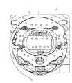
図1に示すように、パチンコ機1の遊技盤2には、作動口3及び大入賞口4が設けられており、遊技盤2は遊技領域を構成している。作動口3は、遊技球5の通路を備えており、その通路入口には羽根6が開閉可能に支持されている。
【0017】
また、大入賞口4の前には、シャッタ7が設けられている。このシャッタ7は、大入賞口4の側部に設けられた図示しない大入賞口用ソレノイドにより作動させられ、大入賞口4を開閉する。詳しくは、当該ソレノイドが励磁状態となることにより、シャッタ7が略水平に傾き、これにより大入賞口4が開かれる。また、ソレノイドが非励磁状態となることにより、シャッタ7が略垂直状態となり、これにより大入賞口4は閉鎖される。
【0018】
遊技盤2の中央部分(大入賞口4の上方)には、可変表示装置としての特別図柄表示装置(以下、単に「表示装置」という)8が組込まれている。表示装置8は、液晶ディスプレイ(LCD)よりなる表示部8aを備えており、ここに複数の(例えば3つの)図柄列が表示される。図柄列は、基本的には、複数種類の図柄によって構成されている。これらの図柄は、特別遊技図柄としての大当たり図柄、外れリーチ図柄及び外れ図柄のいずれかになりうる。
【0019】
表示装置8の表示部8aでは、各図柄列の図柄変動(回転変動)が、遊技球5の作動口3への入賞に基づいて開始させられる。また、大当たり図柄、外れリーチ図柄、外れ図柄の中から1つが選択され、これが停止図柄として設定される。停止図柄とは、各図柄列が図柄変動を停止したときに表示される図柄である。
【0020】
大当たり図柄は、いわゆるリーチ状態を経た後、遊技者に有利な大当たり状態を発生させるための図柄である。詳しくは、全ての図柄列の変動が停止させられたとき、表示されている図柄の組合せが、予め定められた大当たりの組合せ、すなわち、同一種類の図柄が大当たりラインに沿って並んでいるときの同図柄の組合せ(例えば、「7」、「7」、「7」の図柄)となる場合がある。この組合せを構成する図柄が「大当たり図柄」である。大当たりの組合せが成立すると、特別電動役物が作動し(大入賞口4が開かれ)、遊技者にとって有利な大当たり状態の到来、すなわち、より多くの賞球を獲得することが可能となる。
【0021】
表示装置8において、表示部8aの上方には、発光ダイオード(LED)からなる保留ランプ9a,9b,9c,9dが組み込まれている。保留ランプ9a〜9dは、基本的には作動口3への入賞に基づく変動表示の保留毎に点灯させられ、その保留に対応した変動表示の実行に伴い消灯させられる。さらに、パチンコ機1には、遊技の進行に応じて効果音を発生する図示しないスピーカが設けられている。
【0022】
このほかにも、パチンコ機1の複数箇所には、遊技効果を高めるための各種ランプが取付けられている。これらのランプは、例えばランプ風車11、上部コーナー飾り12、下部コーナー飾り13等からなり、遊技の進行に応じて点灯状態(消灯、点灯、点滅等)が適宜変えられるようになっている。なお、上部コーナー飾り12には、遊技者に球切れ状態や入賞状態を報知するべく、球切れランプ及び入賞ランプ等が内蔵されている。
【0023】
本実施の形態では、遊技者の操作に応じて変化するパチンコ機1の遊技状態を検出するべく、遊技盤2には、種々の検出スイッチが取付けられている。これら検出スイッチにより、遊技球5の作動口3への入賞や、大入賞口4への入賞が検出されるようになっている。また、本実施の形態では、各検出スイッチの検出結果に基づきソレノイドや、表示装置8、各保留ランプ9a〜9d、各種ランプ11〜13、スピーカ等をそれぞれ駆動制御するために制御装置が設けられている。制御装置は、読み出し専用メモリ(ROM)、中央処理装置(CPU)、ランダムアクセスメモリ(RAM)等を備えている。ROMは所定の制御プログラムや初期データを予め記憶しており、CPUはROMの制御プログラム等に従って各種演算処理を実行する。
【0024】
次に、本実施の形態の特徴的部分について説明する。
【0025】
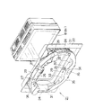
上述した表示装置8は、表示部8aの前方において、該表示部8aを囲むようにして設けられたセンターフレーム21を有している。図2,3に示すように、このセンターフレーム21は、特別遊技領域を構成しており、後部において液晶取付板22を備えているとともに、天井部23、左右両側の側部24及び下部25を有している。天井部23の中央部には天飾り26(図4,図5参照)が設けられ、その両側は遊技球5が案内されうる入口部27となっている。入口部27の両側には肩飾りレンズ28が設けられており、該肩飾りレンズ28に対応する天井部23に当たった遊技球5は、左右両側方へと案内されるようになっている。
【0026】
また、下部25の上面は、ステージ29となっており、該ステージ29上において、遊技者は、遊技球5の挙動を視認することができるようになっている。さらに、左右両側部24には、前記入口部27及びステージ29間を連通する遊技球通路31が形成されている。遊技球通路31は、遊技者が通過中の遊技球5を視認困難となるようカバーで覆われるようにして構成されている。従って、入口部27に入った遊技球5は、図6に示すように、該遊技球通路31を通って(このとき、一時的に遊技球5の視認が困難となる)、ステージ29上へと案内される。
【0027】
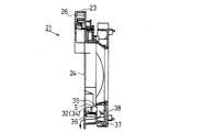
ステージ29は、連続的に高さが異なっており、そのほぼ中央部は山状の凸部32となっており、その左右両側は凹部33となっている。凹部33は、前側ほど低い傾斜面となっており、多くの遊技球5がここから前方へ導出されるようになっている。一方、凸部32の頂部には、後側ほど低くなっている案内溝34が形成されている。前記案内溝34の奥には、遊技球5が通過可能な開口部35が形成されている。また、凹部33下部の開口部35に対応する位置には、遊技球5を前方へ排出するための排出案内部36が設けられている。
【0028】
本実施の形態では、前記開口部35を通過した遊技球5が排出案内部36から円滑に排出されるよう、開口部35の後部にケーシング37が設けられている。つまり、開口部35を通過した遊技球5は、一旦このケーシング37の内部に案内され、ケーシング37の底部から排出案内部36へと導かれる。ここで、このケーシング37には、図4に示すように、常に遊技球5を一方(図3の左方)へ導くためのガイド突起38が突出形成されている。また、万が一ケーシング37内において、遊技球5が詰まったりした場合には、遊技球5を容易に取り出すことができるよう、常には案内されない側の容積が比較的大きめに形成されている(ケーシング37底壁の左右の形状、つまり、角度が異なっている)。
【0029】
図1に示すように、上記排出案内部36は、前記作動口3の直上方に設けられており、該排出案内部36から排出された遊技球5は比較的高い確率で作動口3に入賞しやすく構成されている。
【0030】
また、遊技盤2には多数の釘(図示せず)が植設されている。従って、これら釘に当たった一部の遊技球5は、前記遊技球通路31を通らずとも、ジャンプしてステージ29へと導かれる場合もある。
【0031】
次に、上記のように構成されてなる本実施の形態の作用及び効果について説明する。
【0032】
本実施の形態によれば、遊技者の操作により、遊技盤2上部に打ち込まれた遊技球5は、入口部27からセンターフレーム21へと案内される場合がある。この入口部27から案内された遊技球5は、遊技球通路31を通ってステージ29へと案内される。遊技者は、ステージ29に形成された凹部33及び凸部32を転動する(左右に往復動する)遊技球5の挙動を視認し、楽しむ。
【0033】
本実施の形態では、ステージ29の凸部32に対応して開口部35が設けられ、遊技球5は、この開口部35を通過しうる場合がある。このため、遊技球5が開口部35を通過する場合には、遊技者は、自身にとって何らかの好ましいことが起こるのではないかと期待感をもって遊技を行いうる。従って、いずれの場合にもほぼ同様の挙動によって単にステージから遊技球が落下するに過ぎなかった従来技術に比べて、遊技者は、遊技球5が開口部35を通過することを期待しつつ、はらはらどきどきしながら遊技を行うことができる。その結果、遊技球5が似通った挙動を示すことによる退屈感を抑制することができ、興趣の飛躍的な向上を図ることができる。
【0034】
特に、本実施の形態では、開口部35を通過した遊技球5は、ケーシング37の底部から排出案内部36へと導かれ、該排出案内部36から排出された遊技球5は比較的高い確率で作動口3に入賞しやすい。従って、遊技者は、遊技球5が開口部35を通過することをより期待し、上記作用効果をより確実なものとすることができる。
【0035】
さらに、本実施の形態では、上記開口部35は、凸部32に対応して設けられている。このため、遊技球5が転動しやすい(案内されやすい)凹部33とは異なり、凸部32に乗り上げて開口部35へと案内されるケースは比較的少ない。このため、開口部35に遊技球5が案内されることに稀少価値が生じ、さらに面白味が増す。
【0036】
併せて、前記開口部35は、凸部32の奥に設けられているため、遊技球5が奥行き方向に移動しうる。このため、遊技者は立体的な遊技感覚を堪能することができ、より一層の興趣の向上を図ることができる。
【0037】
加えて、凸部32には、開口部35に遊技球5を案内するための案内溝34が設けられている。従って、遊技者は、この案内溝34の存在により、遊技球5が開口部35の方へと案内されることもありうるのだということを把握することができる。その結果、開口部35には滅多に入らないのではないかという遊技者にとっての疑念を払拭することができ、かかり意味でさらなる興趣の向上を図ることができる。
【0038】
また、本実施の形態では、遊技球通路31を通過中の遊技球5を遊技者が視認することが困難となっている。従って、遊技者にとっては、一旦入口部27に入った遊技球5が一旦隠れた後、突然ステージ29上に現れるるような感覚を覚える。従って、さらに面白味が増す。
【0039】
さらに、本実施の形態では、ステージ29に連続的に高さの異なる凸部32及び凹部33を設けることとした。このため、遊技球5がステージ29上を転動するに際し、遊技球の速度が早められたり遅められたりする。従って、遊技者はかかる特異な挙動を堪能しうる。また、このような特異な挙動を起こさせるに際し、特別な装置を用いてはいないので、コストの増大や制作面での困難性を回避することもできる。
【0040】
尚、本発明は上述した実施の形態の記載内容に限定されるものではなく、従って、発明の趣旨を逸脱しない範囲で、例えば次のように実施してもよい。
【0041】
(a)上記実施の形態では、作動口3を入賞可能な構成としたが、単に通過するのみの場合であってもよい。また、作動口3の代わりに、開口部35を通過した遊技球5が他の入賞口(例えば一般入賞口)等に入賞しやすい構成となっていてもよい。
【0042】
(b)上記実施の形態では、ステージ29の中央に凸部32を、その両側に凹部33を設ける構成としたが、連続的に高さの異なるステージであれば、このような形状に何ら限定されるものではない。例えば、中央部に凹部が形成され、その両側に凸部が形成されたステージであってもよい。
【0043】
(c)上記実施の形態では、表示部8aの周囲を囲むセンターフレーム21を特別遊技領域としたが、他の役物を囲む領域を特別遊技領域としてもよい。
【0044】
(d)上記実施の形態では、凸部32に案内溝34を形成することとしたが、該案内溝34を省略してもよい。
【0045】
(e)上記実施の形態では、凹部33に傾斜面を形成することとしたが、該傾斜面を設けない構成としてもよい。
【0046】
(f)遊技球通路31を通過中の遊技球5を視認可能な構成としてもよい。或いは、全く視認不可能な構成としてもよい。
【0047】
(g)上記実施の形態では、入口部27を2カ所に形成したが、3カ所以上設けてもよいし、1カ所にのみ設けることとしてもよい。また、入口部の開口面積を変更可能な可変入口装置を設けることとしてもよい。
【0048】
(h)上記実施の形態では、開口部35を凸部32の奥に設けることとしたが、ステージ29上における凸部32に直接孔を設け、これを開口部としてもよい。
【0049】
(i)上記実施の形態では、表示部8aを液晶ディスプレイ(LCD)により構成したが、他にも、CRT、ドットマトリックス、LED(エレクトロルミネッセンス)、蛍光表示管等を用いることとしてもよい。
【0050】
(j)本発明は、上記実施の形態とは異なるタイプのパチンコ機にも適用できる。従って、表示装置8のないパチンコ機にも応用できる。また、本発明は、パチンコ機以外にも雀球、アレンジボール等の遊技機にも応用可能である。
【0051】
(k)上記実施の形態における羽根6を省略することとしてもよい。
【0052】
特許請求の範囲の請求項に記載されないものであって、上記実施の形態から把握できる技術的思想について以下に記載する。
【0053】
(1)請求項1に記載の遊技機において、前記開口部は、前記凸部の奥に設けられていることを特徴とする遊技機。
【0054】
(2)請求項1及び上記付記(1)に記載の遊技機において、前記凸部は、前記ステージのほぼ中央に設けられ、その両側に凹部が設けられていることを特徴とする遊技機。
【0055】
(3)請求項1及び上記付記(1)(2)に記載の遊技機において、前記凸部には、前記開口部に遊技球を案内するための案内部が設けられていることを特徴とする遊技機。
【0056】
(4)請求項1及び上記付記(1)〜(3)に記載の遊技機において、前記凹部には、遊技球を再度前記遊技領域へ排出するための排出部が設けられていることを特徴とする遊技機。
【0057】
(5)請求項1及び上記付記(1)〜(4)に記載の遊技機において、前記遊技領域には、遊技者に所定の遊技価値を付与しうる入賞口が設けられており、かつ、当該入賞口は、前記開口部を通った遊技球が入賞しやすい位置に設けられていることを特徴とする遊技機。
【0058】
(6)上記付記(5)に記載の遊技機において、前記入賞口の直上方において、前記ステージの下部には、前記開口部を通った遊技球を再度前記遊技領域に排出するとともに、前記入賞口の方へ案内するための排出案内口が設けられていることを特徴とする遊技機。
【0059】
(7)請求項1及び上記付記(1)〜(6)に記載の遊技機において、前記遊技球通路は、遊技者が通過中の遊技球を視認不可能又は視認困難となるように構成されていることを特徴とする遊技機。
【0060】
(8)請求項1及び上記付記(1)〜(7)に記載の遊技機において、前記特別遊技領域は、少なくとも複数の図柄を変動表示可能な可変表示装置の周囲を囲むセンターフレームによって構成されていることを特徴とする遊技機。
【0061】
(9)上記付記(8)に記載の遊技機において、前記入賞口への遊技球の入賞は、前記可変表示装置における前記図柄の変動表示開始の契機となることを特徴とする遊技機。
【0062】
【発明の効果】
以上詳述したように、本発明の遊技機によれば、遊技領域において遊技球を用いて遊技を行いうるとともに、前記遊技領域に特別遊技領域を設けてなる遊技機において、退屈感を抑え、興趣の向上を図ることができるという優れた効果を奏する。
【図面の簡単な説明】
【図1】一実施の形態におけるパチンコ機の要部を示す正面図である。
【図2】センターフレーム等を示す斜視図である。
【図3】センターフレーム等を示す正面図である。
【図4】図3のA−A線断面図である。
【図5】図3のB−B線断面図である。
【図6】図3のC−C線断面図である。
【符号の説明】
1…遊技機としてのパチンコ機、2…遊技領域を構成する遊技盤、3…作動口、4…大入賞口、5…遊技媒体としての遊技球、8…可変表示装置としての(特別図柄)表示装置、8a…表示部、21…センターフレーム、27…入口部、29…ステージ、31…遊技球通路、32…凸部、33…凹部、34…案内溝、35…開口部、36…排出案内部。[0001]
BACKGROUND OF THE INVENTION
The present invention relates to a gaming machine such as a pachinko machine, and more particularly to a gaming machine which can play a game using a game ball in a game area and has a special game area in the game area.
[0002]
[Prior art]
Conventionally, a pachinko machine equipped with a special symbol display device (variable display device) for variably displaying a plurality of types of symbols and the like in a predetermined arrangement is known as a kind of gaming machine.
[0003]
In this type of pachinko machine, depending on the display pattern (stop pattern) when the variable display on the variable display device is stopped, after passing through the reach state, it becomes a “special game state” or reach state that is advantageous to the player. An “outgoing reach state” that does not become a special gaming state later, or an “outgoing state” that does not go through the reach state and does not become a special gaming state is generated. The stop symbols include a special game symbol (a jackpot symbol) for generating a special game state, a release reach symbol for generating a release reach, and a release symbol for generating a release state.
[0004]
In the pachinko machine as described above, the variable display device starts the variable display of the symbols on the condition that the game ball wins an operating opening provided below the variable display device. Also, a stop symbol corresponding to the game situation is selected from the special game symbol, the missed reach symbol, and the missed symbol, and the variable display is stopped at the selected stop symbol. And when it stops at a jackpot symbol, it is switched so that a special variation prize-winning device will be in a state advantageous to the player (a jackpot state). More specifically, the player can acquire a large amount of prize balls by opening a big prize opening provided at a lower portion of the operation opening or the like.
[0005]
By the way, the above-described variable display device has a display unit for displaying a symbol, and the display unit includes, for example, a liquid crystal screen or a dot matrix screen. Further, conventionally, a resin center frame is generally provided so as to surround the periphery of the display unit.
[0006]
In general, this center frame is composed of a ceiling part located on the upper part, left and right side parts and a lower part, and a ceiling surface for guiding the game ball to the left and right sides is provided on the ceiling part. An entrance for guiding the game ball to the lower part is provided. A stage is formed at the bottom. Furthermore, a game ball passage (also referred to as a warp route) that communicates the entrance and the stage is provided on both the left and right sides, and a decorative lens is provided.
[0007]
When a game ball enters the entrance, the game ball is guided toward the stage through the game ball passage. The game ball guided to the stage makes several reciprocating motions from side to side, then falls forward from the stage, and is discharged again onto the game board surface. At this time, one out of several game balls that have dropped from the stage wins an operating port provided directly below the stage. In other words, the player has the expectation that the game ball will win the operation port from the time when the game ball enters the entrance part until it falls off the stage and is guided toward the operation port. Watch the behavior.
[0008]
[Problems to be solved by the invention]
However, the gaming machines as described above have room for improvement as described below. That is, in the stage, the central part is generally at the lowest position, and the game ball usually falls from the central part or the vicinity thereof. For this reason, all the game balls behaved in a similar manner from the time when they were guided to the stage until they dropped, and as a result, there was a risk of causing the player to feel bored. As a result, there is a risk that the interest will be reduced.
[0009]
The present invention has been made in view of the above-described problems, and the object thereof is a gaming machine in which a game ball can be played in a game area and a special game area is provided in the game area. The object is to provide a gaming machine that can suppress boredom and improve the interest.
[0010]
[Means for Solving the Problems]
In order to achieve the above object, according to the first aspect of the present invention, in the gaming machine in which a game ball can be played using a game ball in the game area and a special game area is provided in the game area, An entrance that can guide a game ball to the special game area, an immovable stage that is provided in the special game area and allows a player to visually observe the behavior of the game ball, and the special game area A game ball passage that communicates between the entrance and the stage so as to guide the game ball that has entered the entrance to the stage from the side of the stage. Are provided with a concave portion and a convex portion having different heights, and a restricting portion for restricting further rolling of the game ball to the rear side is provided at the rear portion of the stage and guided to the stage. A game ball can roll along the concave portion and the convex portion from one side of the stage toward the other side, and the convex portion is provided at substantially the center of the stage. Is provided with a hole that is large enough to cause a ball to enter when rolling the convex part, and the top of the convex part is inclined downward with respect to the hole and the game ball moves the convex part. When rolling, a guide groove that can be guided to the hole is provided depending on the rolling speed, and a game ball that has entered the hole directly or through the guide groove is provided in the game area via the discharge guide port. The concave portion is provided on both sides of the convex portion, and the game ball that has not entered the hole is discharged forward from the lower inclined surface toward the front side of the concave portion. The entrance portion is a game ball that has entered the entrance portion, To have sufficient energy to serial concave and convex portions to be reciprocally rolling right and left, and its gist in that it comprises a sufficient height relative to the stage. In the invention according to
[0011]
(Function)
According to the gaming machine according to the first aspect of the present invention, a game is played using a game ball in the game area.
[0012]
The game balls in the game area can be guided from the entrance to the special game area. The game ball guided from the entrance is guided to the stage provided in the special game area through the game ball passage. The stage is provided with concave and convex portions having different heights almost continuously, and the player visually recognizes and enjoys the behavior of the game ball rolling on the concave and convex portions.
[0013]
In the present invention, an opening is provided corresponding to the convex portion of the stage, and the game ball may pass through the opening provided corresponding to the convex portion. For this reason, when the game ball passes through the opening, the player can play the game with a sense of expectation that something favorable for him may occur. Therefore, in any case, compared with the prior art in which the game ball simply falls from the stage due to almost the same behavior, the player expects the game ball to pass through the opening, While playing games.
[0014]
In particular, in the present invention, the opening is provided in the convex portion. For this reason, unlike the concave portion where the game ball is easy to roll (easy to be guided), there are relatively few cases where the game ball rides on the convex portion and is guided to the opening. For this reason, a rare value arises in being guided to an opening part, and also interestingness increases.
[0015]
DETAILED DESCRIPTION OF THE INVENTION
Hereinafter, an embodiment in which a gaming machine according to the present invention is embodied as a pachinko gaming machine (hereinafter simply referred to as a “pachinko machine”) will be described in detail with reference to the drawings.
[0016]
As shown in FIG. 1, the
[0017]
A shutter 7 is provided in front of the special winning opening 4. The shutter 7 is actuated by a solenoid for a prize winning opening (not shown) provided on the side of the prize winning opening 4 to open and close the prize winning opening 4. Specifically, when the solenoid is in an excited state, the shutter 7 is tilted substantially horizontally, thereby opening the special winning opening 4. Further, when the solenoid is de-energized, the shutter 7 is in a substantially vertical state, whereby the special winning opening 4 is closed.
[0018]
A special symbol display device (hereinafter simply referred to as “display device”) 8 as a variable display device is incorporated in the center portion of the game board 2 (above the special winning opening 4). The
[0019]
In the
[0020]
The jackpot symbol is a symbol for generating a jackpot state that is advantageous to the player after a so-called reach state. Specifically, when all of the symbol row variations are stopped, the displayed symbol combination is a predetermined jackpot combination, that is, when the same type of symbols are lined up along the jackpot line. In some cases, the symbols are combined (for example, symbols “7”, “7”, and “7”). The symbol constituting this combination is the “big hit symbol”. When the jackpot combination is established, the special electric accessory is activated (the jackpot 4 is opened), and it is possible to obtain a jackpot state that is advantageous to the player, that is, to obtain more prize balls.
[0021]
In the
[0022]
In addition to this, various lamps for enhancing the gaming effect are attached to a plurality of locations of the pachinko machine 1. These lamps are composed of, for example, a
[0023]
In the present embodiment, various detection switches are attached to the
[0024]
Next, characteristic portions of the present embodiment will be described.
[0025]
The
[0026]
Further, the upper surface of the
[0027]
The
[0028]
In the present embodiment, a
[0029]
As shown in FIG. 1, the
[0030]
A number of nails (not shown) are implanted in the
[0031]
Next, the operation and effect of the present embodiment configured as described above will be described.
[0032]
According to the present embodiment, the
[0033]
In the present embodiment, an
[0034]
In particular, in this embodiment, the
[0035]
Further, in the present embodiment, the
[0036]
In addition, since the
[0037]
In addition, the
[0038]
Further, in the present embodiment, it is difficult for the player to visually recognize the
[0039]
Furthermore, in the present embodiment, the
[0040]
The present invention is not limited to the description of the above-described embodiment, and therefore may be implemented as follows, for example, without departing from the spirit of the invention.
[0041]
(A) In the above-described embodiment, the
[0042]
(B) In the above embodiment, the
[0043]
(C) In the above embodiment, the
[0044]
(D) In the above embodiment, the
[0045]
(E) In the above embodiment, the inclined surface is formed in the
[0046]
(F) It is good also as a structure which can visually recognize the
[0047]
(G) In the embodiment described above, the
[0048]
(H) In the above embodiment, the
[0049]
(I) In the above embodiment, the
[0050]
(J) The present invention can be applied to a pachinko machine of a different type from the above embodiment. Therefore, the present invention can also be applied to a pachinko machine without the
[0051]
(K) It is good also as omitting the blade | wing 6 in the said embodiment.
[0052]
The technical idea which is not described in the claims and can be grasped from the above embodiment will be described below.
[0053]
(1) The gaming machine according to claim 1, wherein the opening is provided at the back of the convex portion.
[0054]
(2) The gaming machine according to claim 1 and the appendix (1), wherein the convex portion is provided at substantially the center of the stage, and concave portions are provided on both sides thereof.
[0055]
(3) In the gaming machine according to claim 1 and the supplementary notes (1) and (2), the convex portion is provided with a guide portion for guiding a game ball to the opening. To play.
[0056]
(4) In the gaming machine according to claim 1 and the additional notes (1) to (3), the recess is provided with a discharge portion for discharging the game ball to the game area again. A gaming machine.
[0057]
(5) In the gaming machine according to claim 1 and the supplementary notes (1) to (4), the game area is provided with a winning opening that can give a predetermined game value to the player, and The gaming machine is characterized in that the winning opening is provided at a position where a game ball passing through the opening is likely to win.
[0058]
(6) In the gaming machine according to appendix (5), the game ball that has passed through the opening is discharged again to the game area at the lower portion of the stage immediately above the winning opening, and the winning is achieved. A gaming machine characterized in that a discharge guide port is provided for guiding to the mouth.
[0059]
(7) In the gaming machine according to claim 1 and the supplementary notes (1) to (6), the game ball passage is configured such that a player cannot see or difficult to see the game ball being passed. A gaming machine characterized by that.
[0060]
(8) In the gaming machine according to claim 1 and the supplementary notes (1) to (7), the special game area is configured by a center frame surrounding a variable display device capable of variably displaying at least a plurality of symbols. A gaming machine characterized by that.
[0061]
(9) In the gaming machine according to appendix (8), the winning of a game ball in the winning opening serves as an opportunity to start the variable display of the symbol in the variable display device.
[0062]
【The invention's effect】
As described in detail above, according to the gaming machine of the present invention, a game can be performed using a game ball in the gaming area, and in the gaming machine in which a special gaming area is provided in the gaming area, a feeling of boredom is suppressed, There is an excellent effect that the interest can be improved.
[Brief description of the drawings]
FIG. 1 is a front view showing a main part of a pachinko machine according to an embodiment.
FIG. 2 is a perspective view showing a center frame and the like.
FIG. 3 is a front view showing a center frame and the like.
4 is a cross-sectional view taken along line AA in FIG.
5 is a cross-sectional view taken along line BB in FIG.
6 is a cross-sectional view taken along the line CC in FIG. 3;
[Explanation of symbols]
DESCRIPTION OF SYMBOLS 1 ... Pachinko machine as a game machine, 2 ... Game board which comprises a game area, 3 ... Operation opening, 4 ... Big prize opening, 5 ... Game ball as a game medium, 8 ... As a variable display device (special design) Display device, 8a ... display unit, 21 ... center frame, 27 ... inlet part, 29 ... stage, 31 ... game ball passage, 32 ... convex part, 33 ... concave part, 34 ... guide groove, 35 ... opening part, 36 ... discharge Guide section.
Claims (2)
前記遊技領域にある遊技球を前記特別遊技領域に案内することが可能な入口部と、
前記特別遊技領域に設けられ、遊技者が遊技球の挙動を視認することのできる不動のステージと、
前記特別遊技領域に設けられ、前記入口部へ入球した遊技球を前記ステージの側方から前記ステージ上へ案内するべく、前記入口部及びステージ間を連通する遊技球通路とを備え、
前記ステージには、連続的に高さが異なる凹部及び凸部が設けられるとともに、前記ステージの後部にはそれ以上の後部側への遊技球の転動を規制するための規制部が設けられ、前記ステージへ案内された遊技球がステージの一側から他側に向けて前記凹部及び凸部に沿って転動可能となっており、
前記凸部を前記ステージのほぼ中央に設け、
前記凸部の頂部に、遊技球が前記凸部を転動する際、入球することが起こるような大きさの孔を設け、前記凸部の頂部においては、前記孔に対して下方に傾斜するとともに遊技球が前記凸部を転動する際、転動する速度によっては前記孔へ案内可能な案内溝を設け、直接又は前記案内溝を経て前記孔へ入球した遊技球が排出案内口を介して前記遊技領域に設けられた入賞口の直上方に導出させられるよう構成し、
前記凸部の両側に前記凹部を設け、前記孔へ入球しなかった遊技球が前記凹部のうち前側ほど低い傾斜面から前方へ排出されるよう構成し、
前記入口部は、当該入口部へ入球した遊技球が、前記凹部及び凸部を左右に往復転動しうるのに十分なエネルギーを有するべく、前記ステージに対し十分な高さを具備していることを特徴とする遊技機。In a gaming machine in which a game ball can be played using a game ball in the game area and a special game area is provided in the game area,
An entrance capable of guiding a game ball in the game area to the special game area;
An immovable stage provided in the special game area and allowing a player to visually recognize the behavior of the game ball;
A game ball passage that is provided in the special game area and communicates between the entrance and the stage so as to guide the game ball that has entered the entrance to the stage from the side of the stage;
The stage is provided with a concave portion and a convex portion having continuously different heights, and at the rear portion of the stage, a restriction portion for restricting the rolling of the game ball to the rear portion side is provided. The game ball guided to the stage is capable of rolling along the concave and convex portions from one side of the stage to the other side,
The convex portion is provided in the approximate center of the stage,
The top of the convex portion is provided with a hole having a size that allows a game ball to enter when rolling on the convex portion, and the top of the convex portion is inclined downward with respect to the hole. In addition, when the game ball rolls on the convex portion, a guide groove that can be guided to the hole is provided depending on the rolling speed, and the game ball that has entered the hole directly or through the guide groove is a discharge guide port. Configured to be led out directly above the winning opening provided in the gaming area via
The concave portions are provided on both sides of the convex portion, and a game ball that has not entered the hole is configured to be discharged forward from a lower inclined surface toward the front side of the concave portion,
The entrance portion has a sufficient height with respect to the stage so that a game ball that has entered the entrance portion has sufficient energy to be able to reciprocally roll left and right through the concave portion and the convex portion. A gaming machine characterized by
Priority Applications (1)
| Application Number | Priority Date | Filing Date | Title |
|---|---|---|---|
| JP2000378998A JP3888053B2 (en) | 2000-12-13 | 2000-12-13 | Game machine |
Applications Claiming Priority (1)
| Application Number | Priority Date | Filing Date | Title |
|---|---|---|---|
| JP2000378998A JP3888053B2 (en) | 2000-12-13 | 2000-12-13 | Game machine |
Related Parent Applications (1)
| Application Number | Title | Priority Date | Filing Date |
|---|---|---|---|
| JP22207898A Division JP3646526B2 (en) | 1998-08-05 | 1998-08-05 | Game machine |
Related Child Applications (3)
| Application Number | Title | Priority Date | Filing Date |
|---|---|---|---|
| JP2006047001A Division JP3928659B2 (en) | 2006-02-23 | 2006-02-23 | Game machine |
| JP2006046999A Division JP4545699B2 (en) | 2006-02-23 | 2006-02-23 | Game machine |
| JP2006047000A Division JP4545700B2 (en) | 2006-02-23 | 2006-02-23 | Game machine |
Publications (3)
| Publication Number | Publication Date |
|---|---|
| JP2001157742A JP2001157742A (en) | 2001-06-12 |
| JP2001157742A5 JP2001157742A5 (en) | 2005-09-22 |
| JP3888053B2 true JP3888053B2 (en) | 2007-02-28 |
Family
ID=18847464
Family Applications (1)
| Application Number | Title | Priority Date | Filing Date |
|---|---|---|---|
| JP2000378998A Expired - Lifetime JP3888053B2 (en) | 2000-12-13 | 2000-12-13 | Game machine |
Country Status (1)
| Country | Link |
|---|---|
| JP (1) | JP3888053B2 (en) |
Families Citing this family (4)
| Publication number | Priority date | Publication date | Assignee | Title |
|---|---|---|---|---|
| JP2005198874A (en) * | 2004-01-16 | 2005-07-28 | Samii Kk | Game part of pinball game machine |
| JP4423641B2 (en) * | 2004-12-10 | 2010-03-03 | 株式会社ニューギン | Game machine |
| JP2009148645A (en) * | 2009-04-08 | 2009-07-09 | Sanyo Product Co Ltd | Game machine |
| JP2013075242A (en) * | 2013-02-01 | 2013-04-25 | Sanyo Product Co Ltd | Game machine |
-
2000
- 2000-12-13 JP JP2000378998A patent/JP3888053B2/en not_active Expired - Lifetime
Also Published As
| Publication number | Publication date |
|---|---|
| JP2001157742A (en) | 2001-06-12 |
Similar Documents
| Publication | Publication Date | Title |
|---|---|---|
| JP3646526B2 (en) | Game machine | |
| JP2004024549A (en) | Game machine | |
| JP4284638B2 (en) | Game machine | |
| JP3888053B2 (en) | Game machine | |
| JP4708777B2 (en) | Display device for pachinko machine | |
| JP2004105295A (en) | Game machine | |
| JP3928659B2 (en) | Game machine | |
| JP4247322B2 (en) | Bullet ball machine | |
| JP4132843B2 (en) | Game machine | |
| JP4545699B2 (en) | Game machine | |
| JP4545700B2 (en) | Game machine | |
| JP2006115899A (en) | Game machine | |
| JP2003210696A (en) | Game machine | |
| JP2003210690A (en) | Game machine | |
| JP2002136690A (en) | Game machine | |
| JP4756199B2 (en) | Bullet ball machine | |
| JP2004113822A (en) | Game machine | |
| JP4304680B2 (en) | Pachinko machine winning device | |
| JP2004160002A (en) | Game machine | |
| JP6150931B2 (en) | Bullet ball machine | |
| JP2004105764A (en) | Game machine | |
| JP2004105765A (en) | Game machine | |
| JP2004105763A (en) | Game machine | |
| JP2004105766A (en) | Game machine | |
| JP2000024190A (en) | Game machine |
Legal Events
| Date | Code | Title | Description |
|---|---|---|---|
| A521 | Written amendment |
Free format text: JAPANESE INTERMEDIATE CODE: A523 Effective date: 20050411 |
|
| A621 | Written request for application examination |
Free format text: JAPANESE INTERMEDIATE CODE: A621 Effective date: 20050411 |
|
| A131 | Notification of reasons for refusal |
Free format text: JAPANESE INTERMEDIATE CODE: A131 Effective date: 20060801 |
|
| TRDD | Decision of grant or rejection written | ||
| A01 | Written decision to grant a patent or to grant a registration (utility model) |
Free format text: JAPANESE INTERMEDIATE CODE: A01 Effective date: 20061107 |
|
| A61 | First payment of annual fees (during grant procedure) |
Free format text: JAPANESE INTERMEDIATE CODE: A61 Effective date: 20061120 |
|
| R150 | Certificate of patent or registration of utility model |
Free format text: JAPANESE INTERMEDIATE CODE: R150 |
|
| FPAY | Renewal fee payment (event date is renewal date of database) |
Free format text: PAYMENT UNTIL: 20091208 Year of fee payment: 3 |
|
| FPAY | Renewal fee payment (event date is renewal date of database) |
Free format text: PAYMENT UNTIL: 20121208 Year of fee payment: 6 |
|
| FPAY | Renewal fee payment (event date is renewal date of database) |
Free format text: PAYMENT UNTIL: 20121208 Year of fee payment: 6 |
|
| FPAY | Renewal fee payment (event date is renewal date of database) |
Free format text: PAYMENT UNTIL: 20151208 Year of fee payment: 9 |
|
| R250 | Receipt of annual fees |
Free format text: JAPANESE INTERMEDIATE CODE: R250 |
|
| R250 | Receipt of annual fees |
Free format text: JAPANESE INTERMEDIATE CODE: R250 |
|
| R250 | Receipt of annual fees |
Free format text: JAPANESE INTERMEDIATE CODE: R250 |
|
| EXPY | Cancellation because of completion of term |