JP3885331B2 - Engine exhaust purification system - Google Patents
Engine exhaust purification system Download PDFInfo
- Publication number
- JP3885331B2 JP3885331B2 JP01686898A JP1686898A JP3885331B2 JP 3885331 B2 JP3885331 B2 JP 3885331B2 JP 01686898 A JP01686898 A JP 01686898A JP 1686898 A JP1686898 A JP 1686898A JP 3885331 B2 JP3885331 B2 JP 3885331B2
- Authority
- JP
- Japan
- Prior art keywords
- catalyst
- nox
- amount
- enrichment
- upstream
- Prior art date
- Legal status (The legal status is an assumption and is not a legal conclusion. Google has not performed a legal analysis and makes no representation as to the accuracy of the status listed.)
- Expired - Lifetime
Links
Images


Classifications
-
- Y—GENERAL TAGGING OF NEW TECHNOLOGICAL DEVELOPMENTS; GENERAL TAGGING OF CROSS-SECTIONAL TECHNOLOGIES SPANNING OVER SEVERAL SECTIONS OF THE IPC; TECHNICAL SUBJECTS COVERED BY FORMER USPC CROSS-REFERENCE ART COLLECTIONS [XRACs] AND DIGESTS
- Y02—TECHNOLOGIES OR APPLICATIONS FOR MITIGATION OR ADAPTATION AGAINST CLIMATE CHANGE
- Y02T—CLIMATE CHANGE MITIGATION TECHNOLOGIES RELATED TO TRANSPORTATION
- Y02T10/00—Road transport of goods or passengers
- Y02T10/10—Internal combustion engine [ICE] based vehicles
- Y02T10/40—Engine management systems
Landscapes
- Exhaust Gas After Treatment (AREA)
- Electrical Control Of Air Or Fuel Supplied To Internal-Combustion Engine (AREA)
Description
【0001】
【発明の属する技術分野】
この発明はエンジンの排気浄化装置、特にエンジンをリーン(希薄混合気)運転させるものに関する。
【0002】
【従来の技術】
空燃比が理論空燃比(以下ストイキで略称する)よりもリーンのときにはNOxを吸収し、空燃比がストイキよりもリッチになると吸収したNOxを脱離するだけでなく、この脱離したNOxを、リッチ運転において多く排出されるHC、COを還元剤として用いて浄化することが可能な触媒(以下、NOx吸蔵型触媒という)があり、このNOx吸蔵型触媒を排気通路に設けておき、NOx吸蔵型触媒へのNOx吸蔵量が限界にきたと判断したら、ごく短時間だけ空燃比をストイキよりもリッチ側に制御(リッチ化処理)するようにしたものがある(たとえば特開平7−139340号公報参照)。
【0003】
【発明が解決しようとする課題】
ところで、排気通路にNOx吸蔵型触媒が一個しか設けられていない従来装置では、燃費や運転性の点で改善の余地を残している。
【0004】
たとえば、触媒の活性を確保するためは排気通路の上流側(たとえばマニフォールド位置)に搭載することが望ましい。しかしながら、車両搭載上の要件からマニフォールド位置に大型のNOx吸蔵型触媒を搭載することは難しい。
【0005】
そこで、マニフォールド位置に搭載するNOx吸蔵型触媒は小型のものとし、この触媒だけでは不足する触媒容量を確保するため、排気通路の下流側(たとえば床下位置)に第2のNOx吸蔵型触媒を搭載することが考えられる。
【0006】
この場合、マニフォールド位置と床下位置とでは排気温度(触媒温度)が異なり、したがって各触媒に対する最適なリッチ化程度(たとえばリッチ化処理開始時に空燃比をステップ変化させたあと所定の速度で減算していく場合に、リッチ化処理開始時のリッチ量とその後の減算速度)が大きく相違することから、こうした排気温度の大きく相違する複数の位置にNOx吸蔵型触媒を設けたものに対して、従来のリッチ化処理では対応できないのである。
【0007】
また、かりにマニフォールド位置に大型のNOx吸蔵型触媒を搭載できたとしても、一杯にまで吸蔵したNOxに合わせて空燃比のリッチ化程度を大きくしなければならず(リッチ化程度が大きいとトルクショックが生じる)、運転性が悪くなる。
【0008】
そこで本発明は、複数のNOx吸蔵型触媒を用意して、これらを排気通路に直列に配置する一方で、上流側触媒のリーン運転時のNOx吸蔵量を、またこの上流側触媒のリーン運転時のNOx吸蔵量が吸蔵限界となった場合は下流側触媒のリーン運転時のNOx吸蔵量を算出し、所定のリッチ化処理のタイミングとなった場合に、上流側触媒のみがNOxを吸蔵しているときはその吸蔵NOx量に合わせてリッチ化程度を、また上流側触媒に加えて下流側触媒にまでNOxが吸蔵されているときには上流側触媒の吸蔵NOx量と下流側触媒の吸蔵NOx量それぞれのリッチ化処理特性に合わせてリッチ化程度を設定し、このリッチ化程度を用いて空燃比のリッチ化処理を行うことにより、排気通路にNOx吸蔵型触媒が一個しか設けられていない場合より燃費と運転性をともに改善することを目的とする。
【0009】
【課題を解決するための手段】
第1の発明は、図14に示すように、NOx吸蔵型触媒を排気通路31に直列に複数配置する一方で、リーン運転時に上流側触媒32のNOx吸蔵量を、またリーン運転時のこの上流側触媒32のNOx吸蔵量が吸蔵限界となった場合は下流側触媒33のリーン運転時のNOx吸蔵量を算出する手段34と、所定のリッチ化処理のタイミングとなった場合に、上流側触媒32のみがNOxを吸蔵しているときはその吸蔵NOx量及び上流側触媒の触媒温度に合わせてリッチ化程度(たとえばリッチ化処理開始比例分とその後のリッチ減少速度)を、また上流側触媒32に加えて下流側触媒33にまでNOxが吸蔵されているときには上流側触媒32の吸蔵NOx量及び上流側触媒の触媒温度と、下流側触媒33の吸蔵NOx量及び下流側触媒の触媒温度とに合わせてリッチ化程度を設定する手段35と、このリッチ化程度を用いて空燃比のリッチ化処理を行う手段36とを設けた。
【0010】
第2の発明では、第1の発明において所定のリッチ化処理タイミングが、リーン運転からストイキ運転への切換時または運転性に跳ね返りが少ないと考えられる条件(たとえば加速時)のときである。
【0011】
第3の発明では、第1または第2の発明において相対的に触媒容量の小さなものを上流側触媒、相対的に触媒容量の大きなものを下流側触媒とする。
【0012】
第4の発明では、第1から第3までのいずれか一つの発明において上流側触媒のNOx吸蔵限界を触媒温度に応じて設定する。
【0013】
第5の発明では、第1から第4までのいずれか一つの発明においてNOx吸蔵量とそのときの吸入空気流量に応じて、NOx吸蔵型触媒に吸蔵されているNOxの転化に必要なHC、CO量を算出し、この必要HC、CO量に応じてリッチ化程度を設定する。
【0014】
第6の発明では、第1から第5までのいずれか一つの発明においてNOx吸蔵量を算出するとともに、リッチ化程度の設定によりリッチ化処理開始時に空燃比をステップ変化させたあと所定の速度で減算していく場合に、ステップ変化から減算開始までに遅れを持たせる。
【0015】
【発明の効果】
第1、第2の各発明では、排気通路の離れた位置に複数のNOx吸蔵型触媒を設けた場合でも、NOx吸蔵量の算出とリッチ化程度の設定が可能となるほか、リッチ化処理タイミングになったときに、たまたま従来と同じに上流側触媒の吸蔵NOx量が吸蔵限界となった状態であったとすれば、一個のNOx吸蔵型触媒しか設けておらずその触媒容量が大きな従来装置と比べて、触媒容量が小さい分だけ第1、第2の各発明のほうがリッチ化程度が小さくなり、これによってリッチ化処理に伴うトルク変動を従来より抑制できる(運転性の跳ね返りが少ない)。
【0016】
第3の発明では、上流側触媒の吸蔵NOx量が吸蔵限界を越えなていない状態でリッチ化処理タイミングになった場合のリッチ化程度をさらに小さくできる。
【0017】
NOx限界吸蔵量が触媒温度によらず一定値であるのでは、NOx吸蔵能力を有効に活用できないが、第4の発明では、NOx吸蔵限界を触媒温度に応じて設定するので、上流側触媒のNOx吸蔵能力を最大限に活用することができる。
【0018】
第5の発明では、リッチ化程度を求めるに際してマップ検索が不要となるので、メモリ容量の削減が可能となる。
【0019】
NOx吸蔵量を算出するときには、実際のNOx吸蔵量が算出値よりも多くなる場合がないとはいえず、このときリッチ化処理によりNOx吸蔵型触媒へと供給するHC、CO量が足りず、この足りなかったHC、CO量に対応する脱離NOxの分がそのまま排出されてしまうことが考えられる。第6の発明では、こうしたHC、CO量の不足分が生じる事態があるかもしれないことを見込んでやや多めのHC、COが供給されるように、ステップ変化から減算開始までに遅れを持たせたので、リッチ化処理による供給HC、CO量がその分多くなり、確実に脱離NOxを転化できる。
【0020】
【発明の実施の形態】
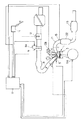
図1は筒内直接噴射式火花点火エンジンの制御システムである。
【0021】
図において、1はエンジン本体、2は燃焼室、3はピストン、4は点火プラグ、5はインジェクタ、8はスワールコントロールバルブ、9はDCモータ等からなるスロットルアクチュエータ9Aにより駆動されるスロットル装置である。なお、筒内直接噴射式火花点火エンジンは、インジェクタ5を燃焼室内に臨んで設けるとともに、燃焼室2、吸気ポートの形状やピストン頂面の形状を工夫したものであるが、本発明はこうした構成そのものに関係しないので、図1には簡単に示している。
【0022】
ECM(エレクトロニックコントロールモジュール)11には、スロットル装置9上流の空気流量を検出するエアフローセンサ12、クランク角センサ(ポジション信号を出力するクランク角センサ13AとREF信号を出力するクランク角センサ13B)、アクセルペダル開度を検出するセンサ14、エンジンの冷却水温を検出するセンサ(図示しない)からの信号が、O2センサ15などからの信号とともに入力され、これらの信号に基づいて、エンジン低負荷時に点火プラグ4付近にだけ混合気を偏在させて燃焼(成層燃焼)を行わせることにより、燃焼室内平均の空燃比がたとえば30〜40といった空燃比での運転を行わせ、エンジン低負荷時を外れると、燃焼室内に均質な混合気を形成させるとともに燃焼室内平均の空燃比をストイキに制御する。
【0023】
さて、排気通路21にNOx吸蔵型触媒を設けて、成層燃焼域で発生するNOxをこのNOx吸蔵型触媒に吸蔵させ、所定のタイミングになると、空燃比のリッチ化処理を行うことにより、NOxを脱離させるとともに、この脱離したNOxを、リッチ運転において多く排出されるHC、COを還元剤として用いて浄化するようにしたものが公知であるが、NOx吸蔵型触媒が一個である従来装置では、燃費や運転性の点で改善の余地を残している。
【0024】
たとえば、触媒の活性を確保するためは排気通路の上流側であるマニフォールド位置に搭載することが望ましい。しかしながら、車両搭載要件からマニフォールド位置に大型のNOx吸蔵型触媒を搭載することが難しい。
【0025】
そこで、マニフォールド位置に搭載するNOx吸蔵型触媒は小型のものとし、この触媒だけでは不足する触媒容量を確保するため、排気通路の下流側である床下位置に第2のNOx吸蔵型触媒を搭載することが考えられる。
【0026】
この場合、マニフォールド位置と床下位置とでは排気温度(触媒温度)が異なり、したがって各触媒に対する最適なリッチ化程度が大きく相違することから、こうした排気温度の大きく相違する複数の位置にNOx吸蔵型触媒を設けたものに対して、従来のリッチ化処理では対応できない。
【0027】
また、かりにマニフォールド位置に大型のNOx吸蔵型触媒を搭載できたとしても、一杯にまで吸蔵したNOxに合わせて空燃比のリッチ化程度を大きくしなければならず(リッチ化程度が大きいとトルクショックが生じる)、運転性が悪くなる。
【0028】
そこで本発明の第1実施形態では、触媒容量の相対的に異なる2つのNOx吸蔵型触媒を用意し、このうち触媒容量の相対的に小さなものを排気通路21の上流側に、触媒容量の相対的に大きなものを下流側に配置する。具体的には、NOx吸蔵型触媒に三元触媒機能を持たせたものを2つ用意し、図1に示したように、上流側のNOx吸蔵型三元触媒22を排気マニフォールドの近くに、また下流側のNOx吸蔵型三元触媒23を車両の床下に配置する。以下、両者を区別するときは、上流側のNOx吸蔵型三元触媒22をマニ触媒、下流側のNOx吸蔵型三元触媒23を床下触媒で略称する。
【0029】
そして、これら2つの触媒22、23を対象として次のようにNOx吸蔵量の算出とリッチ化処理とを行う。
【0030】
〔1〕 成層燃焼時のNOx量は運転条件により異なるため、これをそのときの回転数とエンジン目標トルクとから所定時間当たりに発生するNOx量をマップ検索等により推定し、発生するNOxはマニ触媒22に吸蔵されるものとして、上記の推定値を積算することによってマニ触媒22へのNOx吸蔵量を求める。
【0031】
〔2〕 この結果、マニ触媒22のNOx吸蔵量積算値が吸蔵限界となったら、これ以上マニ触媒に吸蔵できず、発生するNOxは床下触媒23に吸蔵されるものとする。したがって、このときは推定値を積算することによって床下触媒23へのNOx吸蔵量積算値を求める。
【0032】
〔3〕 リッチ化処理のタイミングは、
▲1▼所定のリッチ化処理条件が成立したときと、
▲2▼成層燃焼時(リーン運転時)からストイキ運転への切換時
とする。
【0033】
〔4〕 リッチ化処理のタイミングで、
▲1▼マニ触媒22のみがNOxを吸蔵しているときはその吸蔵NOx量に合わせてリッチ化処理開始タイミングでの比例分とその後のリッチ減少速度を設定し、
▲2▼床下触媒23までがNOxを吸蔵しているときはマニ触媒22の吸蔵NOx量と床下触媒23の吸蔵NOx量の合計に合わせてリッチ化処理開始タイミングでの比例分とその後のリッチ減少速度を設定する。なお、リッチ減少速度が 〔5〕 で後述するNOx脱離速度に対応する。
【0034】
〔5〕 マニ触媒のNOx吸蔵限界と触媒22、23からのNOx脱離速度は触媒温度により異なるため、先願装置(特願平9−1648号)と同様にして各触媒温度を推定し、その推定温度に応じてNOx吸蔵限界と各NOx脱離速度を求める。
【0035】
これをさらに図2を用いて説明すると、これは上記の 〔3〕 ▲2▼かつ 〔4〕 ▲2▼の場合のもので、マニ触媒22に対してはリッチ化処理開始比例分PRS1とリッチ減少速度IRS1を、また床下触媒23に対してはリッチ化処理開始比例分PRS2とリッチ減少速度IRS2を与える。
【0036】
この結果、成層燃焼からストイキ運転への切換タイミングで空燃比フィードバック補正係数α(ストイキ運転時にO2センサ出力に基づいて演算され、ストイキ運転以外では1.0にクランプされる)がPRS1+PRS2の分だけステップ的に大きくなり、その後はIRS1+IRS2(ただし、IRS1が0になった後はIRS2)の速度でαが小さくなる。そして、O2センサ出力がスライスレベルと一致したタイミングで処理を終了し、通常の空燃比フィードバック制御に移行する。
【0037】
ECM11で実行される上記 〔1〕 〜 〔5〕 の制御内容を以下のフローチャートにしたがって説明する。
【0038】
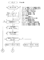
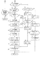
図3、図4はNOx吸蔵量積算値の算出とリッチ化処理を行うためのもので、一定時間毎(たとえば10ms毎)に実行する。
【0039】
ステップ1ではイグニッションキースイッチ(IGN SW)をみてイグニッションキースイッチがONのときはステップ2に進み、マニ触媒22のリッチ化処理開始比例分PRS1、床下触媒23のリッチ化処理開始比例分PRS2、マ二触媒22のリッチ減少速度IRS1、床下触媒23のリッチ減少速度IRS2、マニ触媒用リッチ量DALP1、床下触媒用リッチ量DALP2に初期値の0を入れる。
【0040】
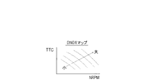
ステップ3では成層燃焼条件かどうかみて、成層燃焼条件であるときは、ステップ4に進み、そのときの回転数NRPMとエンジン目標トルクTTCから図5を内容とするマップを検索して演算時間当たり(10msec当たり)のNOx排出量DNOXを求める。ここで、エンジン目標トルクTTCは基本的にアクセル開度と回転数から定めている。エンジン目標トルクTTCは負荷相当であるため、他の負荷相当値を用いてもかまわない。
【0041】
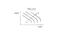
ステップ5では、マニ触媒推定温度TCAT1から図6を内容とするテーブルを検索してマニ触媒22のNOx吸蔵限界値NOXLIM1を求める。この限界値NOXLIM1は図示のように、マニ触媒推定温度TCAT1が上昇するほど大きくなってピークを迎え、さらにマニ触媒推定温度が上昇したときは小さくなる値である。
【0042】
なお、図示しない別のフローにおいて、マニ触媒22と床下触媒23の各温度を推定している(詳細は特願平9−1648号参照)。
【0043】
ステップ6ではマニ触媒22のNOx吸蔵量カウンタ値VNOX1(始動時に0に初期設定)に上記のDNOXを加えた値と上記の限界値NOXLIM1を比較する。VNOX1+DNOX < NOXLIM1であれば、発生するNOxがすべてマニ触媒22に吸蔵されるものとして、ステップ7でVNOX1+DNOXの値を改めてVNOX1とすることで、マニ触媒22のNOx吸蔵量を積算する。VNOX1+DNOX ≧ NOXLIM1であるときは、これ以上マニ触媒に吸蔵できず、発生するNOxは床下触媒23に吸蔵されるものとして、ステップ8で床下触媒23のNOx吸蔵量カウンタ値VNOX2(始動時に0に初期設定)にDNOXを加算した値を改めてVNOX2とすることで、床下触媒23のNOx吸蔵量を積算する。
【0044】
図4のステップ9ではリッチ化処理を行っているかどうかをリッチ化処理フラグよりみる。リッチ化処理を行っていない(リッチ化処理フラグ=0)ときは、ステップ10に進み、リッチ化処理条件であるかどうかみる。リッチ化処理条件の判定は、次の条件、
〈1〉 前回は成層燃焼条件であったこと、
〈2〉 マニ触媒22にNOxが吸蔵されていること、
〈3〉 加速時など運転性に跳ね返りが少ないと考えられる条件であること
を一つずつチェックし、全てを満たす場合にリッチ化処理条件の成立時と判断して、ステップ11に進む。
【0045】
一方、成層燃焼条件でないときは図3のステップ3より図4のステップ30に進み、前回は成層燃焼条件であったかどうかみる。前回は成層燃焼条件であったとき(つまり成層燃焼からストイキ運転への切換時)は、リッチ化処理条件の成立時と同じに、ステップ11に進む。
【0046】
ステップ11では、床下触媒23のNOx吸蔵量カウンタ値VNOX2と0を比較する。VNOX2 ≠ 0のときはステップ12、13に進み、VNOX2と床下触媒推定温度TCAT2から図7を内容とするマップを検索して床下触媒23のリッチ化処理開始比例分PRS2を、また床下触媒推定温度TCAT2から図8を内容とするテーブルを検索して床下触媒23のリッチ減少割合IRS2を求める。VNOX2=0のときは床下触媒23について考慮しなくてもよいので、ステップ14、15に進み、PRS2、IRS2とも0とする。
【0047】
ステップ16、17ではステップ12、13と同様にして、マニ触媒22のNOx吸蔵量カウンタ値VNOX1とマニ触媒推定温度TCAT1から図9を内容とするマップを検索してマニ触媒のリッチ化処理開始比例分PRS1を、またマニ触媒推定温度TCAT1から図10を内容とするテーブルを検索してマニ触媒22のリッチ減少割合IRS1を求める。
【0048】
このようにして求めた比例分PRS1、PRS2をステップ18においてそれぞれ対応するマニ触媒用リッチ量DALP1、床下触媒用リッチ量DALP2に移し、ステップ19ではこれらリッチ量DALP1、DALP2の和をαに加算した値を改めてαとおくことによりαを更新する。続いてリッチ化処理を行うため、ステップ20においてリッチ化処理フラグ=1とする。なお、ステップ18では、次回のリッチ化処理の準備のためVNOX1、VNOX2に0を入れている。
【0049】
このリッチ化処理フラグの “1” へのセットにより、そのままストイキ運転が続く限り(あるいはリッチ化処理条件を外れない限り)次回からステップ9よりステップ21に進み、マニ触媒用リッチ量DALP1とマニ触媒22のリッチ減少割合IRS1とを比較する。このタイミングでのDALP1は前回値であり、リッチ化処理フラグ=1にした次のタイミングでステップ21に進んできたときはDALP1 > IRS1であるので、ステップ22に進み、DALP1(これは前回値)よりIRS1だけ減少させた値を改めてDALP1(これは今回値)とおく。
【0050】
ステップ24、25はステップ21、22と同様である。つまり、床下触媒23についても、リッチ量DALP2とリッチ減少割合IRS2を比較し、DALP2 > IRS2のときはステップ25に進んで、DALP2(これは前回値)よりIRS2だけ減少させた値を改めてDALP2(これは今回値)とおく。
【0051】
ステップ28ではαよりリッチ減少割合IRS2とIRS1の和を差し引いた値を改めてαとおくことによってαを更新する。
【0052】
ステップ22や25の操作を続ける毎にマニ触媒用リッチ量DALP1や床下触媒用リッチ量DALP2が徐々に小さくなり、やがてDALP1 ≦ IRS1やDALP2 ≦ IRS2となったときは、ステップ23や26に進んで、DALP1、IRS1やDALP2、IRS2をともに0とする。
【0053】
ただし、ステップ26の操作を行ったときは、ステップ27でDALP1も0になっているかどうかみて、DALP2に加えてDALP1も0になっているときは、ステップ29に進んでリッチ化処理フラグ=0と(リッチ化処理を終了)する。
【0054】
なお、リッチ化処理の終了後は図示しないフローにおいて、空燃比フィードバック制御が行われる。
【0055】
このように、本実施形態では、触媒容量の相対的に小さなマニ触媒22と触媒容量の相対的に大きな床下触媒23とをこの順に上流側から配置し、成層燃焼時にマニ触媒32のNOx吸蔵量を、またマニ触媒22のNOx吸蔵量積算値が吸蔵限界となった場合は床下触媒23のNOx吸蔵量積算値を算出し、所定のリッチ化処理タイミングで、マニ触媒22のみがNOxを吸蔵しているときは、その吸蔵NOx量に合わせてリッチ化処理開始比例分PRS1とその後のリッチ減少速度IRS1を設定し、マニ触媒22にNOxを吸蔵しきれず、床下触媒23にまで吸蔵させたときには、マニ触媒22の吸蔵NOx量と床下触媒23の吸蔵NOx量の合計に合わせてリッチ化処理開始比例分とその後のリッチ減少速度を設定したので、リッチ化処理タイミングになったときに、たまたま従来と同じにマニ触媒の吸蔵NOx量が吸蔵限界となった状態であったとすれば、一個のNOx吸蔵型触媒しか設けておらずその触媒容量が大きな従来装置と比べて、触媒容量が小さい分だけ本実施形態のほうがリッチ化処理開始比例分が小さくなり、これによってリッチ化処理に伴うトルク変動を従来より抑制できる(運転性の跳ね返りが少ない)。
【0056】
また、一個のNOx吸蔵型触媒しか設けておらずその触媒容量が小さい場合に、吸蔵限界になる度にリッチ化処理を行わなければならない従来装置に対して、本実施形態では、吸蔵NOx量が吸蔵限界に達する度にリッチ化処理を行わなくとも済むので、燃費が悪くなることもない。
【0057】
なお、この実施形態では床下触媒23へのNOx吸蔵量積算値が吸蔵限界に達することがないように床下触媒23にはかなり触媒容量が大きなものを採用しているが、床下触媒23へのNOx吸蔵量積算値が吸蔵限界に達する場合も考慮する必要があるときは、従来装置と同様に、床下触媒23へのNOx吸蔵量積算値が吸蔵限界となったとき、リッチ化処理を行わせればよい。
【0058】
図11のフローチャートは第2実施形態で、第1実施形態の図4に対応する。図4と同一部分には同一のステップ番号を付けている。
【0059】
第2実施形態は、NOx吸蔵量カウンタ値とそのときの吸入空気流量Qaに応じて、各触媒22、23に吸蔵されているNOxの転化に必要なHC、CO量を算出し、この必要HC、CO量に応じてリッチ化処理開始比例分を算出するようにしたものである。言い換えると、第2実施形態は、リッチ化処理開始比例分を求めるに際して、マップ検索を不要としたもので、これによりメモリ容量の削減が可能となる。
【0060】
具体的には、ステップ11でVNOX2 ≠ 0のときステップ41、42に進み、床下触媒23のNOx吸蔵量カウンタ値VNOX2とそのときの吸入空気流量Qaとから
VHCCO2=VNOX2/(KCO×Qa) … ▲1▼
ただし、KCO : CO比重分係数(一定値)
の式により床下触媒23の必要HC、CO量VHCCO2を求め、このVHCCO2から
PRS2=VHCCO2×KK …▲2▼
ただし、KK : 転化効率係数
の式により床下触媒23のリッチ化処理開始比例分PRS2を計算する。
【0061】
ステップ43、44ではステップ41、42と同様にして、マニ触媒22のNOx吸蔵量カウンタ値VNOX1とそのときの吸入空気流量Qaとから
VHCCO1=VNOX1/(KCO×Qa) …▲3▼
ただし、KCO : CO比重分係数
の式によりマニ触媒の必要HC、CO量VHCCO1を求め、
PRS1=VHCCO1×KK …▲4▼
ただし、KK : 転化効率係数
の式によりマニ触媒のリッチ化処理開始比例分PRS1を計算する。
【0062】
ここで、▲1▼、▲3▼式のように、必要HC、CO量(VHCCO2、VHCCO1)をQaに反比例させて求めるのは、同じ量のHC、COを触媒に供給するのに、吸入空気流量Qaが大きいほどリッチ化処理開始比例分が小さくて済むからである。
【0063】
上記のKKはマッチングまたは計算により求める。
【0064】
一方、リッチ化処理条件でないときはVHCCO2、VHCCO1を計算する必要がないため、ステップ10よりステップ45、46に進み、VHCCO2=VHCCO1=0とする。
【0065】
このように、第2実施形態ではリッチ化処理開始比例分RPS1、PRS2を求めるに際して、マップ検索が不要となるので、メモリ容量の削減が可能となる。
【0066】
図12のフローチャートは第3実施形態で、第1実施形態の図4に対応する。図4と同一部分には同一のステップ番号を付けている。
【0067】
さて、第1実施形態ではNOx吸蔵量を算出により求めているため、実際のNOx吸蔵量が算出値よりも多い場合は、リッチ化処理により触媒へと供給するHC、CO量が足りず、この足りなかったHC、CO量に対応する脱離NOxの分がそのまま排出されてしまうことが考えられる。
【0068】
そこで、第3実施形態では、このHC、CO量の不足分があるかもしれないことを見込んでやや多めのHC、COが供給されるように、リッチ量の減算開始にディレイ時間DIRSを持たせたものである。リッチ化処理による供給HC、CO量は図2においてハッチングで示す面積に対応するため、図13に示したようにディレイ時間DIRSを与えることで、リッチ化処理による供給HC、CO量がその分多くなり、確実に脱離NOxを転化できるのである。
【0069】
具体的には、図12においてリッチ化処理の開始タイミングとなったときステップ51でマニ触媒22のNOx吸蔵量カウンタ値VNOX1、床下触媒23のNOx吸蔵量カウンタ値VNOX2を用いて
DIRS=(VNOX1×KDLY1+VNOX2×KDLY2)/Qa
ただし、KDLY1 : マニ触媒22に対するディレイ係数
KDLY2 : 床下触媒23に対するディレイ係数
の式によりリッチ減量ディレイ時間DIRSを計算して今回の処理を終了する。
【0070】
次回からはステップ9よりステップ52に進むので、このリッチ減量ディレイ時間DIRSと0を比較し、DIRS > 0のあいだステップ53に進んでDIRSを Δ Dずつデクリメントするとともに、ステップ54でαをホールドする(前回値を今回値とする)。そして、DIRS ≦ 0となったときステップ21以降に進む。
【0071】
一方、リッチ化処理条件でないときは、ステップ10よりステップ55に進んでDIRS=0とする。
【0072】
このように、第3実施形態ではディレイ時間DIRSの分だけ多くHC、CO量を供給できるので、NOx吸蔵量の算出値よりも実際のNOx吸蔵量が多い場合の脱離NOxの転化不足を解消できる。
【0073】
第3実施形態では第1実施形態に対してリッチ量の減算開始にディレイ時間を持たせた場合で説明したが、第2実施形態に対してリッチ量の減算開始にディレイ時間を持たせるようにすることもできる。また、ディレイ時間でなくても、ディレイ期間でもかまわない。
【0074】
実施形態では、成層燃焼条件の成立時と非成立時とで空燃比を大きく切換える場合で説明したが、これに限られるものではない。たとえば、成層燃焼条件の非成立時(つまり均質燃焼条件の成立時)の運転域をさらにストイキを中心とする運転域と、20〜25といったリーンな空燃比で運転する領域とに分割したものにも本発明を適用することができる。つまり、本発明では、リーン運転時といった場合、成層燃焼時のほか、均質燃焼条件の成立時のうち20〜25といったリーンな空燃比での運転時が含まれる。
【図面の簡単な説明】
【図1】第1実施形態の制御システム図である。
【図2】空燃比のリッチ化処理を説明するための波形図である。
【図3】NOx吸蔵量の算出とリッチ化処理を説明するためのフローチャートである。
【図4】NOx吸蔵量の算出とリッチ化処理を説明するためのフローチャートである。
【図5】演算時間当たりのNOx排出量DNOXの特性図である。
【図6】マニ触媒のNOx吸蔵限界値NOXLIMT1の特性図である。
【図7】床下触媒のリッチ化処理開始比例分PRS2の特性図である。
【図8】床下触媒のリッチ減少割合IRS2の特性図である。
【図9】マニ触媒のリッチ化処理開始比例分PRS1の特性図である。
【図10】マニ触媒のリッチ減少割合IRS1の特性図である。
【図11】第2実施形態のNOx吸蔵量の算出とリッチ化処理を説明するためのフローチャートである。
【図12】第3実施形態のNOx吸蔵量の算出とリッチ化処理を説明するためのフローチャートである。
【図13】第3実施形態の空燃比のリッチ化処理を説明するための波形図である。
【図14】第1の発明のクレーム対応図である。
【符号の説明】
5 インジェクタ
11 ECM
22 マニ触媒(上流側触媒)
23 床下触媒(下流側触媒)[0001]
BACKGROUND OF THE INVENTION
The present invention relates to an exhaust emission control device for an engine, and more particularly, to an engine for lean operation.
[0002]
[Prior art]
When the air-fuel ratio is leaner than the stoichiometric air-fuel ratio (hereinafter abbreviated as stoichiometric), it absorbs NOx, and when the air-fuel ratio becomes richer than stoichiometric, it not only desorbs the absorbed NOx, but also desorbed NOx, There is a catalyst (hereinafter referred to as a NOx storage catalyst) that can be purified using HC and CO that are exhausted in a rich operation as a reducing agent, and this NOx storage catalyst is provided in the exhaust passage to store NOx. If it is determined that the NOx occlusion amount in the type catalyst has reached its limit, there is one in which the air-fuel ratio is controlled to be richer than stoichiometric (riching process) for a very short time (for example, JP-A-7-139340). reference).
[0003]
[Problems to be solved by the invention]
By the way, in the conventional apparatus in which only one NOx occlusion type catalyst is provided in the exhaust passage, there is room for improvement in terms of fuel consumption and drivability.
[0004]
For example, in order to ensure the activity of the catalyst, it is desirable to mount on the upstream side (for example, the manifold position) of the exhaust passage. However, it is difficult to mount a large NOx occlusion type catalyst at the manifold position due to vehicle mounting requirements.
[0005]
Therefore, the NOx occlusion type catalyst mounted at the manifold position is small, and a second NOx occlusion type catalyst is installed downstream of the exhaust passage (for example, under the floor) in order to secure a catalyst capacity that is insufficient with this catalyst alone. It is possible to do.
[0006]
In this case, the exhaust temperature (catalyst temperature) differs between the manifold position and the underfloor position. Therefore, the optimum enrichment degree for each catalyst (for example, the air-fuel ratio is stepped at the start of the enrichment process and then subtracted at a predetermined speed). In this case, the rich amount at the start of the enrichment process and the subsequent subtraction speed) are greatly different from each other. Therefore, the conventional NOx occlusion type catalyst is provided at a plurality of positions where the exhaust temperatures are greatly different. The enrichment process cannot handle this.
[0007]
Even if a large NOx occlusion type catalyst can be installed at the manifold position, the richness of the air-fuel ratio must be increased according to the NOx occluded to the full (torque shock if the degree of enrichment is large). Drivability), drivability deteriorates.
[0008]
Therefore, the present invention prepares a plurality of NOx storage-type catalysts and arranges them in series in the exhaust passage, while the NOx storage amount during the lean operation of the upstream catalyst and the lean operation of the upstream catalyst are also measured. When the NOx occlusion amount reaches the occlusion limit, the NOx occlusion amount during lean operation of the downstream catalyst is calculated, and when the predetermined enrichment processing timing is reached, only the upstream catalyst occludes NOx. If the NOx is stored in the downstream catalyst in addition to the upstream catalyst, the stored NOx amount in the upstream catalyst and the stored NOx amount in the downstream catalyst respectively. By setting the enrichment degree according to the enrichment process characteristics and performing the enrichment process of the air-fuel ratio using this enrichment degree, only one NOx occlusion type catalyst is provided in the exhaust passage. And an object thereof is to improve both fuel economy and drivability of than are.
[0009]
[Means for Solving the Problems]
As shown in FIG. 14, the first invention arranges a plurality of NOx occlusion-type catalysts in series in the
[0010]
In the second invention, in the first invention, the predetermined enrichment processing timing is a time when switching from lean operation to stoichiometric operation or a condition (for example, during acceleration) that is considered to have little rebound in drivability.
[0011]
In the third invention, the catalyst having a relatively small catalyst capacity in the first or second invention is defined as an upstream catalyst, and the catalyst having a relatively large catalyst capacity is defined as a downstream catalyst.
[0012]
In the fourth invention, in any one of the first to third inventions, the NOx storage limit of the upstream catalyst is set according to the catalyst temperature.
[0013]
In the fifth invention, in any one of the first to fourth inventions, HC required for the conversion of NOx stored in the NOx storage-type catalyst according to the NOx storage amount and the intake air flow rate at that time, The amount of CO is calculated, and the degree of enrichment is set according to the required amount of HC and CO.
[0014]
In the sixth invention, the NOx occlusion amount is calculated in any one of the first to fifth inventions, and at a predetermined speed after the air-fuel ratio is step-changed at the start of the enrichment process by setting the enrichment degree. When subtracting, there is a delay from the step change to the start of subtraction.
[0015]
【The invention's effect】
In each of the first and second inventions, even when a plurality of NOx occlusion-type catalysts are provided at positions away from the exhaust passage, it is possible to calculate the NOx occlusion amount and set the degree of enrichment, as well as the enrichment processing timing. If the NOx storage amount of the upstream catalyst happens to be at the storage limit as in the conventional case, the conventional device having only one NOx storage type catalyst and a large catalyst capacity is provided. In comparison, the first and second inventions have a smaller degree of enrichment as the catalyst capacity is smaller, and as a result, torque fluctuations associated with the enrichment process can be suppressed compared to the prior art (the drivability rebound is less).
[0016]
In the third aspect of the present invention, the degree of enrichment when the enrichment processing timing is reached in a state where the amount of NOx stored in the upstream catalyst does not exceed the storage limit can be further reduced.
[0017]
If the NOx limit storage amount is a constant value regardless of the catalyst temperature, the NOx storage capacity cannot be utilized effectively. However, in the fourth aspect of the invention, the NOx storage limit is set according to the catalyst temperature. The NOx storage capacity can be utilized to the maximum.
[0018]
In the fifth aspect of the invention, the map search is not required when obtaining the degree of enrichment, so that the memory capacity can be reduced.
[0019]
When calculating the NOx occlusion amount, it cannot be said that the actual NOx occlusion amount may not be larger than the calculated value. At this time, the amount of HC and CO supplied to the NOx occlusion type catalyst by the enrichment process is insufficient. It is conceivable that the amount of desorbed NOx corresponding to the insufficient HC and CO amounts is discharged as it is. In the sixth invention, there is a delay from the step change to the start of subtraction so that a slightly larger amount of HC and CO may be supplied in anticipation of such a situation where the amount of HC and CO is insufficient. Therefore, the amount of HC and CO supplied by the enrichment process increases correspondingly, and desorbed NOx can be reliably converted.
[0020]
DETAILED DESCRIPTION OF THE INVENTION
FIG. 1 shows a control system for an in-cylinder direct injection spark ignition engine.
[0021]
In the figure, 1 is an engine body, 2 is a combustion chamber, 3 is a piston, 4 is a spark plug, 5 is an injector, 8 is a swirl control valve, and 9 is a throttle device driven by a
[0022]
The ECM (electronic control module) 11 includes an
[0023]
Now, a NOx occlusion type catalyst is provided in the
[0024]
For example, in order to ensure the activity of the catalyst, it is desirable to mount it at the manifold position upstream of the exhaust passage. However, it is difficult to mount a large NOx storage type catalyst at the manifold position due to vehicle mounting requirements.
[0025]
Therefore, the NOx occlusion type catalyst mounted at the manifold position is small, and the second NOx occlusion type catalyst is installed at the underfloor position downstream of the exhaust passage in order to secure a catalyst capacity that is insufficient with this catalyst alone. It is possible.
[0026]
In this case, the exhaust temperature (catalyst temperature) differs between the manifold position and the underfloor position, and therefore the optimum enrichment degree for each catalyst differs greatly. Therefore, the NOx occlusion-type catalyst is located at a plurality of positions where the exhaust temperature differs greatly. However, conventional enrichment processing cannot cope with this.
[0027]
Even if a large NOx occlusion type catalyst can be installed at the manifold position, the richness of the air-fuel ratio must be increased according to the NOx occluded to the full (torque shock if the degree of enrichment is large). Drivability), drivability deteriorates.
[0028]
Therefore, in the first embodiment of the present invention, two NOx occlusion type catalysts having relatively different catalyst capacities are prepared, and a relatively small one of the catalyst capacities is disposed upstream of the
[0029]
Then, the calculation of the NOx occlusion amount and the enrichment process are performed for these two
[0030]
[1] Since the NOx amount during stratified combustion varies depending on the operating conditions, the NOx amount generated per predetermined time is estimated from the rotational speed and engine target torque at that time by a map search or the like. As what is stored in the
[0031]
[2] As a result, if the integrated value of the NOx storage amount of the
[0032]
[3] The timing of the enrichment process is
(1) When a predetermined enrichment processing condition is satisfied,
(2) When switching from stratified charge combustion (during lean operation) to stoichiometric operation
And
[0033]
[4] At the timing of the enrichment process,
(1) When only the
(2) When NOx is occluded up to the
[0034]
[5] Since the NOx occlusion limit of the manifold catalyst and the NOx desorption rate from the
[0035]
This will be further explained with reference to FIG. 2. This is the case of the above [3] (2) and [4] (2). The reduction rate IRS1 is given to the
[0036]
As a result, the air-fuel ratio feedback correction coefficient α (O at the time of stoichiometric operation is switched on) at the switching timing from stratified combustion to stoichiometric operation. 2 Calculated based on the sensor output and clamped to 1.0 except for stoichiometric operation) increases stepwise by the amount of PRS1 + PRS2, and thereafter at a speed of IRS1 + IRS2 (however, after IRS1 becomes 0) α becomes smaller. And O 2 The process is terminated at a timing when the sensor output matches the slice level, and the routine proceeds to normal air-fuel ratio feedback control.
[0037]
The control contents [1] to [5] executed in the
[0038]
FIG. 3 and FIG. 4 are for performing the calculation of the NOx occlusion amount integrated value and the enrichment process, which are executed at regular time intervals (for example, every 10 ms).
[0039]
In
[0040]
In
[0041]
In
[0042]
In another flow (not shown), the temperatures of the
[0043]
In step 6, the value obtained by adding the above DNOX to the NOx occlusion amount counter value VNOX1 (initially set to 0 at the start) of the
[0044]
In
<1> The previous time was stratified combustion conditions,
<2> NOx is stored in the
<3> Conditions that are considered to have little rebound in drivability, such as during acceleration
Are checked one by one, and when all the conditions are satisfied, it is determined that the enrichment processing condition is satisfied, and the process proceeds to step 11.
[0045]
On the other hand, when it is not stratified combustion condition, it progresses from
[0046]
In
[0047]
In
[0048]
The proportional amounts PRS1 and PRS2 thus obtained are transferred to the corresponding manifold catalyst rich amount DALP1 and underfloor catalyst rich amount DALP2 in
[0049]
By setting the rich processing flag to “1”, as long as the stoichiometric operation continues (or as long as the rich processing conditions are not deviated), the process proceeds from
[0050]
[0051]
In
[0052]
Each time the operations in
[0053]
However, when the operation in
[0054]
Note that air-fuel ratio feedback control is performed in a flow (not shown) after the end of the enrichment process.
[0055]
Thus, in the present embodiment, the
[0056]
Further, in the present embodiment, the amount of stored NOx is smaller than that of a conventional device that needs to perform enrichment every time the storage limit is reached when only one NOx storage type catalyst is provided and the catalyst capacity is small. Since it is not necessary to perform the enrichment process every time the storage limit is reached, the fuel efficiency is not deteriorated.
[0057]
In this embodiment, a catalyst having a considerably large capacity is employed as the
[0058]
The flowchart of FIG. 11 is a second embodiment and corresponds to FIG. 4 of the first embodiment. The same steps as those in FIG. 4 are given the same step numbers.
[0059]
In the second embodiment, the amount of HC and CO required for conversion of NOx stored in each of the
[0060]
More specifically, when VNOX2 ≠ 0 in
VHCCO2 = VNOX2 / (KCO × Qa) (1)
KCO: CO specific gravity coefficient (constant value)
The required HC and CO amount VHCCO2 of the
PRS2 = VHCCO2 × KK (2)
KK: Conversion efficiency factor
The proportion PRS2 for starting enrichment of the
[0061]
In
VHCCO1 = VNOX1 / (KCO × Qa) (3)
However, KCO: CO specific gravity coefficient
The required HC and CO amount VHCCO1 of the manifold catalyst are obtained by the following formula:
PRS1 = VHCCO1 × KK (4)
KK: Conversion efficiency factor
Based on the following formula, the proportion PRS1 for starting the enrichment process of the manifold catalyst is calculated.
[0062]
Here, as in the formulas (1) and (3), the required HC and CO amounts (VHCCO2, VHCCO1) are obtained in inverse proportion to Qa because the same amount of HC and CO is supplied to the catalyst. This is because as the air flow rate Qa is larger, the proportion of the enrichment process start is smaller.
[0063]
The above KK is obtained by matching or calculation.
[0064]
On the other hand, when it is not the enrichment processing condition, it is not necessary to calculate VHCCO2 and VHCCO1, so the process proceeds from
[0065]
As described above, in the second embodiment, the map search is not required when obtaining the enrichment process start proportional proportions RPS1 and PRS2, and the memory capacity can be reduced.
[0066]
The flowchart of FIG. 12 is a third embodiment and corresponds to FIG. 4 of the first embodiment. The same steps as those in FIG. 4 are given the same step numbers.
[0067]
In the first embodiment, since the NOx occlusion amount is obtained by calculation, if the actual NOx occlusion amount is larger than the calculated value, the amount of HC and CO supplied to the catalyst by the enrichment process is insufficient. It is conceivable that the amount of desorbed NOx corresponding to the amount of HC and CO that was insufficient is discharged as it is.
[0068]
Therefore, in the third embodiment, a delay time DIRS is provided at the start of the subtraction of the rich amount so that a slightly larger amount of HC and CO is supplied in anticipation that this HC and CO amount may be insufficient. It is a thing. Since the amount of HC and CO supplied by the enrichment process corresponds to the area shown by hatching in FIG. 2, the amount of HC and CO supplied by the enrichment process is increased by giving the delay time DIRS as shown in FIG. Thus, desorbed NOx can be reliably converted.
[0069]
Specifically, when the enrichment process start timing is reached in FIG. 12, the NOx occlusion amount counter value VNOX1 of the
DIRS = (VNOX1 × KDLY1 + VNOX2 × KDLY2) / Qa
However, KDLY1: Delay coefficient for the
KDLY2: Delay coefficient for the
The rich weight loss delay time DIRS is calculated by the following formula, and the current process is terminated.
[0070]
From the next time, the process proceeds from
[0071]
On the other hand, when it is not the enrichment processing condition, the process proceeds from
[0072]
As described above, in the third embodiment, since the amount of HC and CO can be supplied by the delay time DIRS, the lack of conversion of desorbed NOx when the actual NOx storage amount is larger than the calculated value of the NOx storage amount is solved. it can.
[0073]
In the third embodiment, the case where the delay time is given to the start of the subtraction of the rich amount is explained with respect to the first embodiment, but the delay time is given to the start of the subtraction of the rich amount as compared to the second embodiment. You can also Further, the delay period may be used instead of the delay time.
[0074]
In the embodiment, the case has been described in which the air-fuel ratio is largely switched between when the stratified combustion condition is satisfied and when it is not satisfied. For example, the operating range when the stratified combustion condition is not satisfied (that is, when the homogeneous combustion condition is satisfied) is further divided into an operating range centered on stoichiometric and a range operating with a lean air-fuel ratio such as 20-25. The present invention can also be applied. That is, in the present invention, the case of lean operation includes not only stratified combustion but also operation at a lean air-fuel ratio such as 20 to 25 when the homogeneous combustion condition is satisfied.
[Brief description of the drawings]
FIG. 1 is a control system diagram of a first embodiment.
FIG. 2 is a waveform diagram for explaining air-fuel ratio enrichment processing;
FIG. 3 is a flowchart for explaining calculation of NOx occlusion amount and enrichment processing;
FIG. 4 is a flowchart for explaining calculation of NOx occlusion amount and enrichment processing.
FIG. 5 is a characteristic diagram of NOx emission amount DNOX per calculation time.
FIG. 6 is a characteristic diagram of a NOx storage limit value NOXLIMT1 of the manifold catalyst.
FIG. 7 is a characteristic diagram of the proportion PRS2 for starting the underfloor catalyst enrichment process.
FIG. 8 is a characteristic diagram of an underfloor catalyst rich reduction ratio IRS2.
FIG. 9 is a characteristic diagram of a manifold catalyst enrichment start proportional proportion PRS1.
FIG. 10 is a characteristic diagram of a rich reduction ratio IRS1 of the manifold catalyst.
FIG. 11 is a flowchart for explaining calculation and enrichment processing of a NOx occlusion amount according to the second embodiment.
FIG. 12 is a flowchart for explaining calculation and enrichment processing of a NOx occlusion amount according to the third embodiment.
FIG. 13 is a waveform diagram for explaining the air-fuel ratio enrichment process of the third embodiment.
FIG. 14 is a view corresponding to a claim of the first invention.
[Explanation of symbols]
5 Injector
11 ECM
22 Manifold catalyst (upstream catalyst)
23 Underfloor catalyst (downstream catalyst)
Claims (6)
リーン運転時に上流側触媒のNOx吸蔵量を、またリーン運転時のこの上流側触媒のNOx吸蔵量が吸蔵限界となった場合は下流側触媒のリーン運転時のNOx吸蔵量を算出する手段と、
所定のリッチ化処理のタイミングとなった場合に、上流側触媒のみがNOxを吸蔵しているときはその吸蔵NOx量及び上流側触媒の触媒温度に合わせてリッチ化程度を、また上流側触媒に加えて下流側触媒にまでNOxが吸蔵されているときには上流側触媒の吸蔵NOx量及び上流側触媒の触媒温度と、下流側触媒の吸蔵NOx量及び下流側触媒の触媒温度とに合わせてリッチ化程度を設定する手段と、
このリッチ化程度を用いて空燃比のリッチ化処理を行う手段と
設けたことを特徴とするエンジンの排気浄化装置。While a plurality of NOx storage-type catalysts are arranged in series in the exhaust passage,
Means for calculating the NOx occlusion amount of the upstream catalyst during the lean operation, and if the NOx occlusion amount of the upstream catalyst during the lean operation reaches the occlusion limit, means for calculating the NOx occlusion amount during the lean operation of the downstream catalyst;
If only the upstream catalyst stores NOx when the predetermined enrichment processing timing is reached, the enrichment level is set according to the stored NOx amount and the catalyst temperature of the upstream catalyst, and the upstream catalyst is also stored. In addition, when NOx is occluded in the downstream catalyst, it is enriched according to the amount of NOx stored in the upstream catalyst and the catalyst temperature of the upstream catalyst, and the amount of NOx stored in the downstream catalyst and the catalyst temperature of the downstream catalyst. Means to set the degree,
An engine exhaust gas purification apparatus comprising means for performing an air-fuel ratio enrichment process using the degree of enrichment.
Priority Applications (1)
| Application Number | Priority Date | Filing Date | Title |
|---|---|---|---|
| JP01686898A JP3885331B2 (en) | 1998-01-29 | 1998-01-29 | Engine exhaust purification system |
Applications Claiming Priority (1)
| Application Number | Priority Date | Filing Date | Title |
|---|---|---|---|
| JP01686898A JP3885331B2 (en) | 1998-01-29 | 1998-01-29 | Engine exhaust purification system |
Publications (2)
| Publication Number | Publication Date |
|---|---|
| JPH11210526A JPH11210526A (en) | 1999-08-03 |
| JP3885331B2 true JP3885331B2 (en) | 2007-02-21 |
Family
ID=11928197
Family Applications (1)
| Application Number | Title | Priority Date | Filing Date |
|---|---|---|---|
| JP01686898A Expired - Lifetime JP3885331B2 (en) | 1998-01-29 | 1998-01-29 | Engine exhaust purification system |
Country Status (1)
| Country | Link |
|---|---|
| JP (1) | JP3885331B2 (en) |
Families Citing this family (2)
| Publication number | Priority date | Publication date | Assignee | Title |
|---|---|---|---|---|
| JP6237395B2 (en) * | 2014-03-26 | 2017-11-29 | 三菱自動車工業株式会社 | Exhaust gas purification device for internal combustion engine |
| US10697340B1 (en) * | 2019-01-31 | 2020-06-30 | Hyundai Motor Company | After treatment system and after treatment method for lean-burn engine |
-
1998
- 1998-01-29 JP JP01686898A patent/JP3885331B2/en not_active Expired - Lifetime
Also Published As
| Publication number | Publication date |
|---|---|
| JPH11210526A (en) | 1999-08-03 |
Similar Documents
| Publication | Publication Date | Title |
|---|---|---|
| KR100336549B1 (en) | Evaporative fuel supply control device of lean-burn internal combustion engine | |
| US6216450B1 (en) | Exhaust emission control system for internal combustion engine | |
| US20010013221A1 (en) | Fuel supply conrol system for internal combustion engine | |
| GB2383279A (en) | A method and system for determining storage efficiency of an exhaust gas treatment device | |
| JPH11336589A (en) | Vapor recovery control system of direct injection spark ignition engine | |
| JP4208012B2 (en) | Exhaust gas purification device for internal combustion engine | |
| EP1524424A2 (en) | Direct fuel injection/spark ignition engine control device | |
| US6553757B1 (en) | NOx purge air/fuel ratio selection | |
| US6490855B1 (en) | Fueling control during emission control device purging | |
| JP3885331B2 (en) | Engine exhaust purification system | |
| JP2000352336A (en) | Exhaust emission control system for internal combustion engine | |
| JP3132357B2 (en) | Control device for internal combustion engine assisted by electric motor | |
| JPH1150884A (en) | Engine control device | |
| JP2001073749A (en) | Exhaust gas purifier for internal combustion engine of vehicle use | |
| JP3873537B2 (en) | Exhaust gas purification device for internal combustion engine | |
| JP2727801B2 (en) | Engine control method and control device | |
| JP3427881B2 (en) | Internal combustion engine | |
| US6874312B2 (en) | Oxidant storage capacity estimation | |
| JP3478135B2 (en) | Exhaust gas purification device for internal combustion engine | |
| JP3334635B2 (en) | Exhaust gas purification device for internal combustion engine | |
| JP4339599B2 (en) | In-cylinder injection internal combustion engine control device | |
| JP4269279B2 (en) | Control device for internal combustion engine | |
| JP3123438B2 (en) | Exhaust gas purification device for internal combustion engine | |
| JP3520731B2 (en) | Engine exhaust purification device | |
| JP4666542B2 (en) | Exhaust gas purification control device for internal combustion engine |
Legal Events
| Date | Code | Title | Description |
|---|---|---|---|
| A977 | Report on retrieval |
Free format text: JAPANESE INTERMEDIATE CODE: A971007 Effective date: 20060213 |
|
| A131 | Notification of reasons for refusal |
Free format text: JAPANESE INTERMEDIATE CODE: A131 Effective date: 20060221 |
|
| A521 | Written amendment |
Free format text: JAPANESE INTERMEDIATE CODE: A523 Effective date: 20060420 |
|
| TRDD | Decision of grant or rejection written | ||
| A01 | Written decision to grant a patent or to grant a registration (utility model) |
Free format text: JAPANESE INTERMEDIATE CODE: A01 Effective date: 20061031 |
|
| A61 | First payment of annual fees (during grant procedure) |
Free format text: JAPANESE INTERMEDIATE CODE: A61 Effective date: 20061113 |
|
| R150 | Certificate of patent or registration of utility model |
Free format text: JAPANESE INTERMEDIATE CODE: R150 |
|
| FPAY | Renewal fee payment (event date is renewal date of database) |
Free format text: PAYMENT UNTIL: 20101201 Year of fee payment: 4 |
|
| FPAY | Renewal fee payment (event date is renewal date of database) |
Free format text: PAYMENT UNTIL: 20111201 Year of fee payment: 5 |
|
| FPAY | Renewal fee payment (event date is renewal date of database) |
Free format text: PAYMENT UNTIL: 20121201 Year of fee payment: 6 |
|
| FPAY | Renewal fee payment (event date is renewal date of database) |
Free format text: PAYMENT UNTIL: 20121201 Year of fee payment: 6 |
|
| FPAY | Renewal fee payment (event date is renewal date of database) |
Free format text: PAYMENT UNTIL: 20131201 Year of fee payment: 7 |
|
| EXPY | Cancellation because of completion of term |