JP3882969B2 - Tilt detector - Google Patents
Tilt detector Download PDFInfo
- Publication number
- JP3882969B2 JP3882969B2 JP06896898A JP6896898A JP3882969B2 JP 3882969 B2 JP3882969 B2 JP 3882969B2 JP 06896898 A JP06896898 A JP 06896898A JP 6896898 A JP6896898 A JP 6896898A JP 3882969 B2 JP3882969 B2 JP 3882969B2
- Authority
- JP
- Japan
- Prior art keywords
- crosstalk
- filter coefficient
- recording
- recording track
- read
- Prior art date
- Legal status (The legal status is an assumption and is not a legal conclusion. Google has not performed a legal analysis and makes no representation as to the accuracy of the status listed.)
- Expired - Fee Related
Links
Images


Classifications
-
- G—PHYSICS
- G11—INFORMATION STORAGE
- G11B—INFORMATION STORAGE BASED ON RELATIVE MOVEMENT BETWEEN RECORD CARRIER AND TRANSDUCER
- G11B7/00—Recording or reproducing by optical means, e.g. recording using a thermal beam of optical radiation by modifying optical properties or the physical structure, reproducing using an optical beam at lower power by sensing optical properties; Record carriers therefor
- G11B7/08—Disposition or mounting of heads or light sources relatively to record carriers
- G11B7/09—Disposition or mounting of heads or light sources relatively to record carriers with provision for moving the light beam or focus plane for the purpose of maintaining alignment of the light beam relative to the record carrier during transducing operation, e.g. to compensate for surface irregularities of the latter or for track following
- G11B7/095—Disposition or mounting of heads or light sources relatively to record carriers with provision for moving the light beam or focus plane for the purpose of maintaining alignment of the light beam relative to the record carrier during transducing operation, e.g. to compensate for surface irregularities of the latter or for track following specially adapted for discs, e.g. for compensation of eccentricity or wobble
- G11B7/0956—Disposition or mounting of heads or light sources relatively to record carriers with provision for moving the light beam or focus plane for the purpose of maintaining alignment of the light beam relative to the record carrier during transducing operation, e.g. to compensate for surface irregularities of the latter or for track following specially adapted for discs, e.g. for compensation of eccentricity or wobble to compensate for tilt, skew, warp or inclination of the disc, i.e. maintain the optical axis at right angles to the disc
-
- G—PHYSICS
- G11—INFORMATION STORAGE
- G11B—INFORMATION STORAGE BASED ON RELATIVE MOVEMENT BETWEEN RECORD CARRIER AND TRANSDUCER
- G11B7/00—Recording or reproducing by optical means, e.g. recording using a thermal beam of optical radiation by modifying optical properties or the physical structure, reproducing using an optical beam at lower power by sensing optical properties; Record carriers therefor
- G11B7/004—Recording, reproducing or erasing methods; Read, write or erase circuits therefor
- G11B7/005—Reproducing
Description
【0001】
【発明の属する技術分野】
本発明は、記録媒体としての記録ディスクから記録情報の読み取りを行う情報読取手段とこの記録ディスクとの間に生じている傾きを検出するティルト検出装置に関する。
【0002】
【従来の技術】
光学式記録媒体としての記録ディスクから記録情報を正確に読み取る為には、この記録ディスクの記録面に対して垂直に読取ビームを照射する必要がある。しかしながら、記録ディスク自体に反りが生じていると、この記録ディスクの記録面に対して垂直に読取ビームを照射することが出来なくなり、情報読取精度が低下してしまう。
【0003】
そこで、かかる記録ディスクから記録情報の再生を行う記録情報再生装置においては、情報読取手段としてのピックアップと記録ディスクとの間に生じている傾きを検出すべく、ティルトセンサが設けられている。この際、かかるティルトセンサによって検出された傾きに応じた分だけピックアップ全体を傾けたり、あるいは、このピックアップによって読み取られた読取信号に対してこの傾きに応じた所望の信号処理を施すことにより、情報読取精度の低下を抑えるのである。
【0004】
図1は、上記の如き記録ディスクとピックアップとの間に生じている傾きを検出するティルトセンサ4を記録情報再生装置に設置した際の概略構成を示す図である。
図1において、ティルトセンサ4におけるビーム発生器41は、スピンドルモータ2によって回転駆動される記録ディスク3の記録面上の互いに異なる2カ所の位置に照射されるような発散光を照射する。光検出器42は、かかる発散光が記録ディスク3の記録面に照射された際の反射光の一部を受光して、この受光量に応じたレベルを有する第1検出信号を減算器44に供給する。一方、光検出器43は、ビーム発生器41を中心にして光検出器42と対象となる位置に配置される。光検出器43は、上記発散光が記録ディスク3の記録面に照射された際の反射光の一部を受光して、この受光量に応じたレベルを有する第2検出信号を減算器44に供給する。減算器44は、これら第1検出信号及び第2検出信号のレベル差を求めこれをティルトエラー信号として出力する。尚、上記ビーム発生器41、光検出器42及び43各々は、図示せぬピックアップと同一平行面に設置されているものとする。
【0005】
ここで、上記記録ディスク3の記録面とピックアップとの平行関係が保たれていると、光検出器42及び43各々が受光する反射光量は同一となるので、ティルトエラー信号は"0"となる。一方、記録ディスク3に反り等が生じていると、光検出器42及び43各々が受光する反射光量は互いに異なったものとなり、この反射光量の差に応じたティルトエラー信号が出力されるのである。
【0006】
しかしながら、このようなティルトセンサ4を記録情報再生装置内に搭載すると装置規模が大になるという問題が発生し、更に、その取り付けの際に、ティルトセンサ4をピックアップとの平行関係を保つ位置に正確に設置しなければならないので設置精度が要求されるという問題があった。
【0007】
【発明が解決しようとする課題】
本発明は、かかる問題を解決すべくなされたものであり、記録ディスクとピックアップとの間に生じている傾きを小規模な構成にて、かつ精度良く検出することが出来るティルト検出装置を提供することを目的とする。
【0008】
【課題を解決するための手段】
請求項1記載によるティルト検出装置は、記録トラックが形成されている記録ディスクから記録情報の読み取りを行う情報読取手段と前記記録ディスクとの間に生じている傾きを検出するティルト検出装置であって、互いに隣接する3本の記録トラックの内の中央の記録トラックのディスク内周側に隣接する第1隣接記録トラックから読み取られた第1読取信号と誤差値との相関により第1フィルタ係数を求める第1フィルタ係数演算手段と、前記第1読取信号に対して前記第1フィルタ係数に基づくフィルタリング処理を施すことにより前記第1隣接記録トラックからのクロストークを示す第1クロストーク信号を生成する第1フィルタと、前記中央の記録トラックのディスク外周側に隣接する第2隣接記録トラックから読み取られた第2読取信号と前記誤差値との相関により第2フィルタ係数を求める第2フィルタ係数演算手段と、前記第2読取信号に対して前記第2フィルタ係数に基づくフィルタリング処理を施すことにより前記第2隣接記録トラックからのクロストークを示す第2クロストーク信号を生成する第2フィルタと、前記中央の記録トラックから読み取られたメイン読取信号から前記第1クロストーク信号及び第2クロストーク信号を減算することによりクロストーク除去読取信号を生成する減算手段と、前記クロストーク除去読取信号と所定値との誤差を検出しこれを前記誤差値として得る誤差検出手段と、からなるクロストーク除去手段と、前記第1フィルタ係数と前記第2フィルタ係数との差に基づき前記記録ディスクの表面に対する前記情報読取手段のディスク半径方向における傾きを求める手段と、を有する。
又、請求項2記載によるティルト検出装置は、記録トラックが形成されている記録ディスクに読取ビームを照射した際の反射光を光電変換して読取信号を得る情報読取手段と前記記録ディスクとの間に生じている傾きを検出するティルト検出装置であって、互いに隣接する3本の記録トラックの内の中央の記録トラックに対する前記情報読取手段による読取位置を基準とし、前記中央の記録トラックのディスク内周側に隣接する第1隣接記録トラック上での前記読取位置よりも読取方向において前後に所定距離だけ離れた位置各々から読み取られた第1読取信号と誤差値との相関により第1フィルタ係数を求める第1フィルタ係数演算手段と、前記第1読取信号に対して前記第1フィルタ係数に基づくフィルタリング処理を施すことにより前記第1隣接記録トラックからのクロストークを示す第1クロストーク信号を生成する第1フィルタと、前記中央の記録トラックのディスク外周側に隣接する第2隣接記録トラック上での前記読取位置よりも読取方向において前後に前記所定距離だけ離れた位置各々から読み取られた第2読取信号と前記誤差値との相関により第2フィルタ係数を求める第2フィルタ係数演算手段と、前記第2読取信号に対して前記第2フィルタ係数に基づくフィルタリング処理を施すことにより前記第2隣接記録トラックからのクロストークを示す第2クロストーク信号を生成する第2フィルタと、前記メイン読取信号から前記第1クロストーク信号及び第2クロストーク信号を減算することによりクロストーク除去読取信号を生成する減算手段と、前記クロストーク除去読取信号と所定値との誤差を検出しこれを前記誤差値として得る誤差検出手段と、からなるクロストーク除去手段と、前記第1フィルタ係数と前記第2フィルタ係数との差に基づき前記記録ディスクの表面に対する前記情報読取手段のディスク半径方向における傾きを求める手段と、を有する。
【0009】
【発明の実施の形態】
以下、本発明の実施例について説明する。
図2は、本発明によるティルト検出装置を備えた記録情報再生装置の構成を示す図である。
図2において、情報読取手段としてのピックアップ100に搭載されているレーザ発振器103から発せられたレーザビームは、グレーティング104を介して3本の情報読取ビームに分割される。これら3本の情報読取ビームは、ハーフミラー105及び対物レンズ106を介して記録ディスク3に照射される。尚、これら3本の情報読取ビーム各々は、記録ディスク3の記録面上において互いに隣接する3本の記録トラックに夫々照射される。
【0010】
図3は、上記3本の情報読取ビームにより記録ディスク3の記録面に生じる各ビームスポットを示す図である。
図3に示されるように、中央のビームスポットPBがトラックTに形成されている場合には、その隣接トラック(T+1)にビームスポットPAが形成される。更に、トラックTの隣接トラック(T−1)にはビームスポットPCが形成される。
【0011】
これらビームスポットPA、PB及びPC各々からの反射光は、対物レンズ106及びハーフミラー105を介して光検出器107に照射される。光検出器107は、夫々独立した光検出器107a〜107cからなる。
光検出器107aは、上記ハーフミラー105を介して供給されたビームスポットPAからの反射光を光電変換して得られた読取信号をA/D変換器5aに供給する。光検出器107bは、上記ハーフミラー105を介して供給されたビームスポットPBからの反射光を光電変換して得られた読取信号をA/D変換器5bに供給する。光検出器107cは、上記ハーフミラー105を介して供給されたビームスポットPCからの反射光を光電変換して得られた読取信号をA/D変換器5cに供給する。
【0012】
尚、図3に示されるように、ビームスポットPA及びPBはその読取方向において距離Lだけ離れており、又、ビームスポットPB及びPC間も上記距離Lだけ離れているものとする。
A/D変換器5a〜5c各々は、上記光検出器107a〜107c各々から供給された読取信号を夫々順次サンプリングして読取サンプル値系列SA〜SC各々を得る。
【0013】
遅延回路7は、読取サンプル値系列SBを(L/V)時間だけ遅延させた遅延読取サンプル値系列SB’をクロストーク除去回路40に供給する。遅延回路8は、読取サンプル値系列SCを2・(L/V)時間だけ遅延させた遅延読取サンプル値系列SC’をクロストーク除去回路40に供給する。この際、A/D変換器5aから出力された上記読取サンプル値系列SAは直接、上記クロストーク除去回路40に供給される。
【0014】
尚、上記"L"は、図3に示されるが如きビームスポットPB及びPC(PA)間の距離であり、"V"は、記録ディスク3に対するピックアップ100の読取線速度である。
すなわち、図3に示されるように、読取サンプル値系列SAにおける1読取サンプル値が記録トラック(T+1)上における位置Q1から読み取られたものである場合には、遅延読取サンプル値系列SB’における1読取サンプル値は、記録トラックT上における位置Q2から読み取られたものである。又、この際、遅延読取サンプル値系列SC’における1読取サンプル値は、記録トラック(T−1)上における位置Q3から読み取られたものである。これら位置Q1〜Q3各々は、図3に示されるように、記録ディスク3上の同一の半径ライン上に存在するものである。
【0015】
このように、クロストーク除去回路40には、互いに隣接する3つの記録トラック各々の同一半径ライン上に存在する位置各々から読み取られた3系統の読取サンプル値系列(SA、SB’、SC’)が供給されることになるのである。
クロストーク除去回路40は、上記読取サンプル値系列SA及び遅延読取サンプル値系列及SC’に基づいて、遅延読取サンプル値系列SB’に重畳している隣接トラック{記録トラック(T+1)及び(T−1)}各々からのクロストーク成分を除去したクロストーク除去読取サンプル値系列Pを得る。2値判定回路9は、このクロストーク除去読取サンプル値系列Pに基づいて2値の再生データを求めて出力する。
【0016】
図4は、上記クロストーク除去回路40の内部構成を示す図である。
図4に示されるクロストーク除去回路40は、記録ディスク3上において互いに隣接している3つの記録トラック(T+1)、T、及び(T−1)各々から読み取られた各読取サンプル値系列に対し、例えばLMS(least mean square)アルゴリズムの如き適応アルゴリズムに基づく適応信号処理を施すことにより、クロストークの除去された読取サンプル値系列Pを得るものである。
【0017】
図4において、フィルタ係数演算回路401は、上記読取サンプル値系列SA、及び後述する誤差検出回路400から供給された誤差値eに基づいてフィルタ係数C1を求める。係数乗算器411は、読取サンプル値系列SAにおける各読取サンプル値に上記フィルタ係数C1を乗算して得られた乗算結果をクロストークCR1とし、これを加算器430に供給する。遅延回路421は、上記読取サンプル値系列SAを所定時間t(後述する)だけ遅延させて、これを遅延読取サンプル値系列SAd1としてフィルタ係数演算回路402、係数乗算器412、及び遅延回路422に供給する。
【0018】
フィルタ係数演算回路402は、上記遅延読取サンプル値系列SAd1及び誤差検出回路400から供給された誤差値eに基づいてフィルタ係数C2を求める。係数乗算器412は、遅延読取サンプル値系列SAd1における各読取サンプル値に上記フィルタ係数C2を乗算して得られた乗算結果をクロストークCR2とし、これを加算器430に供給する。遅延回路422は、上記遅延読取サンプル値系列SAd1を更に上記所定時間tだけ遅延させたものを遅延読取サンプル値系列SAd2としてフィルタ係数演算回路403及び係数乗算器413に供給する。
【0019】
フィルタ係数演算回路403は、上記遅延読取サンプル値系列SAd2及び誤差検出回路400から供給された誤差値eに基づいてフィルタ係数C3を求める。係数乗算器413は、遅延読取サンプル値系列SAd2における各読取サンプル値にかかるフィルタ係数C3を乗算して得られた乗算結果をクロストークCR3とし、これを加算器430に供給する。加算器430は、上記クロストークCR1〜CR3各々を加算したものを、上記図3に示されるが如き記録トラック(T+1)から記録トラックTへの総クロストークCR(T+1)として、これを減算器480に供給する。
【0020】
フィルタ係数演算回路404は、上記遅延読取サンプル値系列SC’、及び誤差検出回路400から供給された上記誤差値eに基づいてフィルタ係数C4を求める。係数乗算器454は、遅延読取サンプル値系列SC’における各読取サンプル値にかかるフィルタ係数C4を乗算して得られた乗算結果をクロストークCR4とし、これを加算器470に供給する。遅延回路461は、上記遅延読取サンプル値系列SC’を上記所定時間tだけ遅延させて、これを遅延読取サンプル値系列SCd1としてフィルタ係数演算回路405、係数乗算器455、及び遅延回路462に供給する。
【0021】
フィルタ係数演算回路405は、上記遅延読取サンプル値系列SCd1及び上記誤差検出回路400から供給された誤差値eに基づいてフィルタ係数C5を求める。係数乗算器455は、上記遅延読取サンプル値系列SCd1における各読取サンプル値にかかるフィルタ係数C5を乗算して得られた乗算結果をクロストークCR5とし、これを加算器470に供給する。遅延回路462は、上記遅延読取サンプル値系列SCd1を更に上記所定時間tだけ遅延させたものを遅延読取サンプル値系列SCd2としてフィルタ係数演算回路406及び係数乗算器456に供給する。
【0022】
フィルタ係数演算回路406は、上記遅延読取サンプル値系列SCd2及び上記誤差検出回路400から供給された誤差値eに基づいてフィルタ係数C6を求める。係数乗算器456は、上記遅延読取サンプル値系列SCd2における各読取サンプル値にかかるフィルタ係数C6を乗算して得られた乗算結果をクロストークCR6とし、これを加算器470に供給する。加算器470は、上記クロストークCR4〜CR6各々を加算したものを上記図3に示されるが如き記録トラック(T−1)から記録トラックTへの総クロストークCR(T-1)とし、これを減算器480に供給する。遅延回路490は、上記遅延読取サンプル値系列SB’を更に上記所定時間tだけ遅延させたものを遅延読取サンプル値系列SBd1とし、これを上記減算器480に供給する。
【0023】
減算器480は、かかる遅延読取サンプル値系列SBd1から、上記総クロストークCR(T+1)及び総クロストークCR(T-1)各々を減算したものをクロストーク除去読取サンプル値系列Pとして出力する。
誤差検出回路400は、クロストーク除去読取サンプル値系列Pにおける各読取サンプル値と、これら読取サンプル値各々として取り得る理想サンプル値各々との誤差を検出し、これを上記誤差値eとして上記フィルタ係数演算回路401〜406各々に供給する。例えば、誤差検出回路400は、上記クロストーク除去読取サンプル値系列P中における連続した3つの読取サンプル値列において、その値が正から負、又は負から正へと推移した際の中央のサンプル、すなわちゼロクロスサンプルを抽出し、これが実際の"0"値に対して有する誤差を上記誤差値eとするのである。この際、フィルタ係数演算回路401〜406の各々は、かかる誤差値eが"0"に収束して行くように、各フィルタ係数C1〜C6各々を更新して行く。
【0024】
尚、上記フィルタ係数演算回路401〜406の各々は同一の内部構成を有するものであり、これを図5に示す。
図5において、相関演算回路Mは、上記読取サンプル値系列(SA、SAd1、SAd2、SC’、SCd1、SCd2)と上記誤差値eとの相関を求め、その相関値を積分器INに供する。相関演算回路Mは、例えば、読取サンプル値系列と誤差値eとの乗算により両者の相関に対応した相関値を得るのである。積分器INは、かかる相関値を積分してその積分結果をフィルタ係数Cとして出力する。例えば、図4におけるフィルタ係数演算回路401は、読取サンプル値系列SAと上記誤差値eとの相関を求め、この相関に対応した相関値を積分して平均化したものをフィルタ係数C1として出力するのである。
【0025】
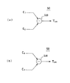
ここで、図2のティルトエラー算出回路50は、例えば図7(a)に示されるような加算器AD1、AD2、及び減算器SUBから構成され、クロストーク除去回路40内において生成されれた上記フィルタ係数C1、C3、C4及びC6を用いた以下の演算を実行することによりティルトエラー信号TERRを求める。
【0026】
【数2】
TERR=(C1+C3)−(C4+C6)
又は、
【0027】
【数3】
TERR=(C4+C6)−(C1+C3)
すなわち、読取対象となっている記録トラックの内周側に隣接する記録トラック(T+1)からのクロストークを除去すべく生成されたフィルタ係数(C1、C3)と、外周側に隣接する記録トラック(T−1)からのクロストークを除去すべく生成されたフィルタ係数(C4、C6)との大小バランスに基づき、ピックアップ100及び記録ディスク3間の傾きに対応したティルトエラー信号TERRを得るのである。
【0028】
以上の如く、本発明によるティルトエラー検出装置は、クロストーク除去回路40及びティルトエラー算出回路50から構成される。
ここで、かかるティルトエラー検出装置の動作を説明するにあたり、先ず、クロストーク除去回路40の動作について、図6(a)〜図6(c)を参照しつつ説明する。
【0029】
先ず、図6(a)は、ピックアップ100と記録ディスク3の記録面との間にティルトが生じていない場合に、ピックアップ100からの情報読取ビームを記録トラックT上の位置A1に照射した際に形成されるビームスポットPBの形態を示す図である。
図6(a)に示されるように、ピックアップ100と記録ディスク3の記録面との間にティルトが生じていない場合には、記録トラックT上の位置A1を中心にしてほぼ真円のビームスポットPBが形成される。
【0030】
一方、ピックアップ100と記録ディスク3の記録面との間に図6(b)に示されるが如きティルトが生じていると、かかる図6(b)に示されるようにビームスポットPBはディスク内周側に延びた形態となる。この際、ビームスポットPBは、記録トラックTのディスク内周側に隣接する記録トラック(T+1)上の一部、例えば、記録トラックT上の位置A1の真横の位置A6を照射することになる。更に、この記録トラックTよりもディスク外周側には、サイドローブPSが形成される。この際、かかるサイドローブPSは、記録トラックTのディスク外周側に隣接する記録トラック(T−1)上における、上記位置A1よりも読取方向において前後に以下に示す距離Ltだけ離れた位置A2及びA3を照射することになる。
【0031】
【数4】
{(0.65*λ/NA)2-Tp2}1/2 < Lt < {(λ/NA)2-Tp2}1/2
λ:読取ビームの波長
NA:対物レンズ106の開口数
Tp:記録トラック間のピッチ
従って、ピックアップ100と記録ディスク3の記録面との間に上記図6(b)に示されるが如きティルトが生じている場合に、ピックアップ100が記録トラックT上の位置A1から記録情報の読み取りを行った際に得られた読取サンプル値系列SB中には、
ディスク内周側に隣接している記録トラック(T+1)上の位置A6
ディスク外周側に隣接している記録トラック(T−1)上の位置A2及びA3
各々からのクロストークが重畳することになるのである。
【0032】
一方、ピックアップ100と記録ディスク3の記録面との間に、図6(c)に示されるが如きティルトが生じている場合には、かかる図6(c)に示されるようにビームスポットPBはディスク外周側に延びた形態となる。この際、かかるビームスポットPBは、記録トラックTのディスク外周側に隣接する記録トラック(T−1)上の一部、例えば、記録トラックT上の位置A1の真横の位置A7を照射することになる。更に、この記録トラックTよりもディスク内周側には、サイドローブPSが形成される。この際、かかるサイドローブPSは、記録トラックTのディスク内周側に隣接する記録トラック(T+1)上における、上記位置A1よりも読取方向において前後に以下に示す距離Ltだけ離れた位置A4及びA5を照射することになる。
【0033】
【数5】
{(0.65*λ/NA)2-Tp2}1/2 < Lt < {(λ/NA)2-Tp2}1/2
λ:読取ビームの波長
NA:対物レンズ106の開口数
Tp:記録トラック間のピッチ
従って、ピックアップ100と記録ディスク3の記録面との間に上記図6(c)に示されるが如きティルトが生じている場合に、ピックアップ100が記録トラックT上の位置A1から記録情報の読み取りを行った際に得られた読取サンプル値系列SB中には、
ディスク外周側に隣接している記録トラック(T−1)上の位置A7、
ディスク内周側に隣接している記録トラック(T+1)上の位置A4及びA5
各々からのクロストークが重畳することになるのである。
【0034】
このように、ピックアップ100及び記録ディスク3間にティルトがあると、記録トラックT上の位置A1から読み取られた読取信号中には、かかる記録トラックTに隣接している記録トラック(T+1)又は(T−1)上における上記位置A1から読取方向に前後Ltだけ離れた位置(A4及びA5、又はA2及びA3)からのクロストークが重畳されるのである。
【0035】
そこで、図4に示されるクロストーク除去回路40においては、先ず、上記図6に示されている記録トラック(T+1)上における位置A5、A6、及びA4各々からのクロストーク成分、並びに記録トラック(T−1)上における位置A3、A7、及びA2各々からのクロストーク成分を求める。ここで、これらクロストーク成分各々を、記録トラックT上における位置A1から読み取られた読取サンプル値から減算することにより、クロストークの除去された読取サンプル値系列を得るのである。
【0036】
このように、隣接記録トラック(T+1)からのクロストーク成分と、隣接記録トラック(T−1)からのクロストーク成分との大小バランスは、そのまま図6に示されるが如きピックアップ100と記録ディスク3の記録面との間に生じているティルトに対応している。
従って、記録トラック(T+1)からのクロストーク成分を除去すべく生成された上記フィルタ係数C1及びC3と、記録トラック(T−1)からのクロストーク成分を除去すべく生成された上記フィルタ係数C4及びC6との大小バランスによっても、図6に示されるが如きティルト状態を検知することが出来るのである。
【0037】
尚、図7(a)に示される演算では、フィルタ係数C1及びC3を夫々加算した値と、フィルタ係数C4及びC6を夫々加算した値との差分をティルトエラーとしているが、上記フィルタ係数C1とC4との差分、又はフィルタ係数C3とC6との差分によりティルトエラーを求めるようにしても良い。
例えば、ティルトエラー算出回路50の内部構成を図7(b)に示されるが如きものとし、記録トラック(T+1)からのクロストーク成分を除去すべく生成された上記フィルタ係数C1と、記録トラック(T−1)からのクロストーク成分を除去すべく生成された上記フィルタ係数C4との差分、すなわち、
【0038】
【数6】
TERR=C1−C4
又は、
【0039】
【数7】
TERR=C4−C1
なる演算にてティルトエラー信号TERRを求めるのである。
又、ティルトエラー算出回路50の内部構成を図7(c)に示されるが如きものとして、記録トラック(T+1)からのクロストーク成分を除去すべく生成されたフィルタ係数C3と、記録トラック(T−1)からのクロストーク成分を除去すべく生成されたフィルタ係数C6との差分、すなわち、
【0040】
【数8】
TERR=C3−C6
又は、
【0041】
【数9】
TERR=C6−C3
なる演算によってティルトエラー信号TERRを求めるのである。
更に、上記フィルタ係数C1とC6との差分、又はフィルタ係数C3とC4との差分によりティルトエラーを求めるようにしても良い。
【0042】
例えば、ティルトエラー算出回路50の内部構成を図8(a)に示されるが如きものとし、記録トラック(T+1)からのクロストーク成分を除去すべく生成された上記フィルタ係数C1と、記録トラック(T−1)からのクロストーク成分を除去すべく生成された上記フィルタ係数C6との差分、すなわち、
【0043】
【数10】
TERR=C1−C6
又は、
【0044】
【数11】
TERR=C6−C1
なる演算にてティルトエラー信号TERRを求めるのである。
又、ティルトエラー算出回路50の内部構成を図8(b)に示されるが如きものとし、記録トラック(T+1)からのクロストーク成分を除去すべく生成された上記フィルタ係数C3と、記録トラック(T−1)からのクロストーク成分を除去すべく生成された上記フィルタ係数C4との差分、すなわち、
【0045】
【数12】
TERR=C3−C4
又は、
【0046】
【数13】
TERR=C4−C3
なる演算にてティルトエラー信号TERRを求めるのである。
要するに、読取対象となっている記録トラックから読み取られた読取信号に生じている誤差値とディスク内周側に隣接する記録トラックから読み取られた読取信号との相関により求めた第1フィルタ係数(C1、C3)と、上記誤差値とディスク外周側に隣接する記録トラックから読み取られた読取信号との相関により求めた第2フィルタ係数(C4、C6)との大小バランスによってティルトエラーを求めるような構成であれば良いのである。
【0047】
よって、かかる構成によれば、記録情報再生装置内にティルトセンサ等を設置せずとも精度良くティルト検出を行うことが可能となるのである。
【図面の簡単な説明】
【図1】ティルトセンサ4を備えた記録情報再生装置の構成の一例を示す図である。
【図2】本発明によるティルト検出装置を備えた記録情報再生装置の構成を示す図である。
【図3】ビームスポットPA〜PCと、記録ディスク3上の各記録トラックとの位置関係を示す図である。
【図4】クロストーク除去回路40の内部構成を示す図である。
【図5】フィルタ係数演算回路401〜406各々の内部構成の一例を示す図である。
【図6】ビームスポットと中央の記録トラック及び隣接する記録トラックとの位置関係を説明する為の図である。
【図7】ティルトエラー算出回路50の内部構成の一例を示す図である。
【図8】ティルトエラー算出回路50の内部構成の一例を示す図である。
【主要部分の符号の説明】
3 記録ディスク
40 クロストーク除去回路
50 ティルトエラー算出回路
100 ピックアップ
401〜406 フィルタ係数演算回路[0001]
BACKGROUND OF THE INVENTION
The present invention relates to a tilt detection apparatus that detects an inclination generated between an information reading unit that reads recorded information from a recording disk as a recording medium and the recording disk.
[0002]
[Prior art]
In order to accurately read recorded information from a recording disk as an optical recording medium, it is necessary to irradiate a reading beam perpendicular to the recording surface of the recording disk. However, if the recording disk itself is warped, it becomes impossible to irradiate the reading beam perpendicularly to the recording surface of the recording disk, and the information reading accuracy is lowered.
[0003]
Therefore, in a recording information reproducing apparatus that reproduces recording information from such a recording disk, a tilt sensor is provided in order to detect an inclination generated between the pickup as the information reading means and the recording disk. At this time, the entire pickup is tilted by an amount corresponding to the tilt detected by the tilt sensor, or a desired signal processing corresponding to the tilt is performed on the read signal read by the pickup, thereby obtaining information. This reduces the decrease in reading accuracy.
[0004]
FIG. 1 is a diagram showing a schematic configuration when a tilt sensor 4 for detecting an inclination generated between a recording disk and a pickup as described above is installed in a recorded information reproducing apparatus.
In FIG. 1, the beam generator 41 in the tilt sensor 4 irradiates divergent light that irradiates two different positions on the recording surface of the
[0005]
Here, when the parallel relationship between the recording surface of the
[0006]
However, when such a tilt sensor 4 is mounted in a recorded information reproducing apparatus, there arises a problem that the scale of the apparatus becomes large. Further, when the tilt sensor 4 is attached, the tilt sensor 4 is placed in a position that maintains a parallel relationship with the pickup. There is a problem that installation accuracy is required because it must be installed accurately.
[0007]
[Problems to be solved by the invention]
The present invention has been made to solve such a problem, and provides a tilt detection device capable of accurately detecting an inclination generated between a recording disk and a pickup with a small configuration. For the purpose.
[0008]
[Means for Solving the Problems]
Claim 1The tilt detection device according to the present invention is a tilt detection device that detects an inclination generated between an information reading means for reading recorded information from a recording disk on which a recording track is formed and the recording disk., Of the three recording tracks adjacent to each otherThe first read signal read from the first adjacent recording track adjacent to the inner circumference side of the central recording trackAnd mistakeObtain the first filter coefficient by correlation with the difference valueA first filter coefficient calculating unit configured to generate a first crosstalk signal indicating crosstalk from the first adjacent recording track by performing a filtering process based on the first filter coefficient on the first read signal; 1 filter andThe second filter coefficient is obtained from the correlation between the second read signal read from the second adjacent recording track adjacent to the outer peripheral side of the disk of the central recording track and the error value.SecondFilter coefficient calculation means;A second filter that generates a second crosstalk signal indicating crosstalk from the second adjacent recording track by performing a filtering process on the second read signal based on the second filter coefficient; and the central recording. Subtracting means for generating a crosstalk removal read signal by subtracting the first crosstalk signal and the second crosstalk signal from the main read signal read from the track, and an error between the crosstalk removal read signal and a predetermined value And error detection means for detecting the error value as the error value;,A crosstalk removing means comprising:Between the first filter coefficient and the second filter coefficient;differenceBased on the recording diskAgainst the surface ofSaid information reading meansIn the radial direction of the diskMeans for obtaining an inclination.
According to a second aspect of the present invention, there is provided a tilt detection apparatus between an information reading means for obtaining a read signal by photoelectrically converting reflected light when a read beam is irradiated onto a recording disk on which a recording track is formed, and the recording disk. A tilt detecting device for detecting a tilt occurring in the disk, wherein a position of the central recording track among the three recording tracks adjacent to each other is determined based on a reading position by the information reading means. The first filter coefficient is determined by the correlation between the first read signal read from each position separated by a predetermined distance back and forth in the reading direction from the reading position on the first adjacent recording track adjacent to the circumferential side and the error value. First filter coefficient calculation means to be obtained, and applying a filtering process based on the first filter coefficient to the first read signal A first filter for generating a first crosstalk signal indicating crosstalk from the first adjacent recording track, and reading from the reading position on the second adjacent recording track adjacent to the outer peripheral side of the disk of the central recording track Second filter coefficient computing means for obtaining a second filter coefficient by correlation between the second read signal read from each position separated by the predetermined distance back and forth in the direction and the error value, and for the second read signal A second filter that generates a second crosstalk signal indicating crosstalk from the second adjacent recording track by performing a filtering process based on the second filter coefficient; and the first crosstalk signal from the main read signal; Subtracting means for generating a crosstalk removal read signal by subtracting the second crosstalk signal; An error detection unit that detects an error between the talk removal read signal and a predetermined value and obtains the error value as the error value, and based on a difference between the first filter coefficient and the second filter coefficient. Means for obtaining an inclination of the information reading means in the disk radial direction with respect to the surface of the recording disk..
[0009]
DETAILED DESCRIPTION OF THE INVENTION
Examples of the present invention will be described below.
FIG. 2 is a diagram showing a configuration of a recorded information reproducing apparatus provided with a tilt detecting apparatus according to the present invention.
In FIG. 2, a laser beam emitted from a
[0010]
FIG. 3 is a diagram showing each beam spot generated on the recording surface of the
As shown in FIG. 3, when the central beam spot PB is formed on the track T, the beam spot PA is formed on the adjacent track (T + 1). Further, a beam spot PC is formed on the track (T-1) adjacent to the track T.
[0011]
Reflected light from each of these beam spots PA, PB, and PC is applied to the
The photodetector 107a supplies a read signal obtained by photoelectrically converting the reflected light from the beam spot PA supplied through the
[0012]
As shown in FIG. 3, the beam spots PA and PB are separated by a distance L in the reading direction, and the beam spots PB and PC are also separated by the distance L.
Each of the A /
[0013]
The delay circuit 7 supplies to the crosstalk removal circuit 40 a delayed read sample value series SB ′ obtained by delaying the read sample value series SB by (L / V) time. The
[0014]
Note that “L” is the distance between the beam spot PB and PC (PA) as shown in FIG. 3, and “V” is the reading linear velocity of the
That is, as shown in FIG. 3, one read sample value in the read sample value series SA is at a position Q on the recording track (T + 1).11 read sample value in the delayed read sample value series SB ', the position Q on the recording track T is read.2Is read from. At this time, one read sample value in the delayed read sample value series SC 'is a position Q on the recording track (T-1).ThreeIs read from. These positions Q1~ QThreeEach exists on the same radial line on the
[0015]
As described above, the
Based on the read sample value series SA and the delayed read sample value series and SC ′, the
[0016]
FIG. 4 is a diagram showing an internal configuration of the
The
[0017]
In FIG. 4, the filter
[0018]
The filter
[0019]
The filter coefficient
[0020]
The filter
[0021]
The filter
[0022]
The filter
[0023]
The
The
[0024]
Each of the filter coefficient
In FIG. 5, the correlation calculation circuit M is connected to the read sample value series (SA, SAd1, SAd2, SC ’, SCd1, SCd2) And the error value e, and the correlation value is supplied to the integrator IN. The correlation calculation circuit M obtains a correlation value corresponding to the correlation between the read sample value series and the error value e, for example. The integrator IN integrates the correlation value and outputs the integration result as a filter coefficient C. For example, the filter
[0025]
Here, the tilt
[0026]
[Expression 2]
TERR= (C1+ CThree)-(CFour+ C6)
Or
[0027]
[Equation 3]
TERR= (CFour+ C6)-(C1+ CThree)
That is, the filter coefficient (C) generated to remove crosstalk from the recording track (T + 1) adjacent to the inner circumference side of the recording track to be read.1, CThree) And a filter coefficient (C) generated to remove crosstalk from the recording track (T-1) adjacent to the outer peripheral side.Four, C6) And a tilt error signal T corresponding to the inclination between the
[0028]
As described above, the tilt error detection apparatus according to the present invention includes the
Here, in describing the operation of the tilt error detection apparatus, first, the operation of the
[0029]
First, FIG. 6A shows an information reading beam from the
As shown in FIG. 6A, when there is no tilt between the
[0030]
On the other hand, when a tilt as shown in FIG. 6B occurs between the
[0031]
[Expression 4]
{(0.65 * λ / NA)2-Tp2}1/2 <Lt <{(Λ / NA)2-Tp2}1/2
λ: Reading beam wavelength
NA: Numerical aperture of the
Tp: Pitch between recording tracks
Accordingly, when the tilt as shown in FIG. 6B occurs between the
Position A on the recording track (T + 1) adjacent to the inner circumference side of the disc6
Position A on the recording track (T-1) adjacent to the outer periphery of the disc2And AThree
Crosstalk from each will be superimposed.
[0032]
On the other hand, when a tilt as shown in FIG. 6 (c) occurs between the
[0033]
[Equation 5]
{(0.65 * λ / NA)2-Tp2}1/2 <Lt <{(Λ / NA)2-Tp2}1/2
λ: Reading beam wavelength
NA: Numerical aperture of the
Tp: Pitch between recording tracks
Accordingly, when the tilt as shown in FIG. 6C occurs between the
Position A on the recording track (T-1) adjacent to the outer periphery of the disc7,
Position A on the recording track (T + 1) adjacent to the inner circumference side of the discFourAnd AFive
Crosstalk from each will be superimposed.
[0034]
Thus, if there is a tilt between the
[0035]
Therefore, in the
[0036]
In this way, the magnitude balance between the crosstalk component from the adjacent recording track (T + 1) and the crosstalk component from the adjacent recording track (T-1) is directly shown in FIG. This corresponds to the tilt occurring between the recording surface and the recording surface.
Therefore, the filter coefficient C generated to remove the crosstalk component from the recording track (T + 1).1And CThreeAnd the filter coefficient C generated to remove the crosstalk component from the recording track (T-1).FourAnd C6The tilt state as shown in FIG. 6 can also be detected by the magnitude balance.
[0037]
In the calculation shown in FIG. 7A, the filter coefficient C1And CThreeAnd the filter coefficient CFourAnd C6The difference from the value obtained by adding each of the values is defined as a tilt error.1And CFourOr filter coefficient CThreeAnd C6The tilt error may be obtained based on the difference between.
For example, the internal configuration of the tilt
[0038]
[Formula 6]
TERR= C1-CFour
Or
[0039]
[Expression 7]
TERR= CFour-C1
The tilt error signal TERRIs demanded.
Further, assuming that the internal structure of the tilt
[0040]
[Equation 8]
TERR= CThree-C6
Or
[0041]
[Equation 9]
TERR= C6-CThree
The tilt error signal TERRIs demanded.
Further, the filter coefficient C1And C6Or filter coefficient CThreeAnd CFourThe tilt error may be obtained based on the difference between.
[0042]
For example, the internal configuration of the tilt
[0043]
[Expression 10]
TERR= C1-C6
Or
[0044]
## EQU11 ##
TERR= C6-C1
The tilt error signal TERRIs demanded.
Also, the internal configuration of the tilt
[0045]
[Expression 12]
TERR= CThree-CFour
Or
[0046]
[Formula 13]
TERR= CFour-CThree
The tilt error signal TERRIs demanded.
In short, the first filter coefficient (C) obtained from the correlation between the error value generated in the read signal read from the recording track to be read and the read signal read from the recording track adjacent to the inner circumference side of the disc.1, CThree) And the second filter coefficient (C) obtained by the correlation between the error value and the read signal read from the recording track adjacent to the outer periphery of the disk.Four, C6It is sufficient if the tilt error is obtained by a balance between the above and the other.
[0047]
Therefore, according to such a configuration, it is possible to accurately detect the tilt without installing a tilt sensor or the like in the recorded information reproducing apparatus.
[Brief description of the drawings]
FIG. 1 is a diagram illustrating an example of a configuration of a recorded information reproducing apparatus including a tilt sensor 4;
FIG. 2 is a diagram showing a configuration of a recorded information reproducing apparatus including a tilt detecting device according to the present invention.
3 is a diagram showing a positional relationship between beam spots PA to PC and recording tracks on the
4 is a diagram showing an internal configuration of a
FIG. 5 is a diagram illustrating an example of an internal configuration of each of filter coefficient
FIG. 6 is a diagram for explaining the positional relationship between a beam spot, a central recording track, and an adjacent recording track.
7 is a diagram showing an example of an internal configuration of a tilt
8 is a diagram showing an example of an internal configuration of a tilt
[Explanation of main part codes]
3 recording discs
40 Crosstalk elimination circuit
50 Tilt error calculation circuit
100 pickup
401-406 Filter coefficient arithmetic circuit
Claims (4)
互いに隣接する3本の記録トラックの内の中央の記録トラックのディスク内周側に隣接する第1隣接記録トラックから読み取られた第1読取信号と誤差値との相関により第1フィルタ係数を求める第1フィルタ係数演算手段と、前記第1読取信号に対して前記第1フィルタ係数に基づくフィルタリング処理を施すことにより前記第1隣接記録トラックからのクロストークを示す第1クロストーク信号を生成する第1フィルタと、前記中央の記録トラックのディスク外周側に隣接する第2隣接記録トラックから読み取られた第2読取信号と前記誤差値との相関により第2フィルタ係数を求める第2フィルタ係数演算手段と、前記第2読取信号に対して前記第2フィルタ係数に基づくフィルタリング処理を施すことにより前記第2隣接記録トラックからのクロストークを示す第2クロストーク信号を生成する第2フィルタと、前記中央の記録トラックから読み取られたメイン読取信号から前記第1クロストーク信号及び第2クロストーク信号を減算することによりクロストーク除去読取信号を生成する減算手段と、前記クロストーク除去読取信号と所定値との誤差を検出しこれを前記誤差値として得る誤差検出手段と、からなるクロストーク除去手段と、
前記第1フィルタ係数と前記第2フィルタ係数との差に基づき前記記録ディスクの表面に対する前記情報読取手段のディスク半径方向における傾きを求める手段と、を有することを特徴とするティルト検出装置。A tilt detection device for detecting an inclination generated between an information reading means for reading recorded information from a recording disk on which a recording track is formed and the recording disk ,
Determining a first filter coefficient by the correlation between the erroneous difference value between the first read signal read from the first adjacent recording tracks adjacent to the disk inner circumference side of the recording track center of the three adjacent recording tracks from each other A first filter coefficient calculating unit configured to generate a first crosstalk signal indicating crosstalk from the first adjacent recording track by performing a filtering process based on the first filter coefficient on the first read signal; A first filter and second filter coefficient calculation means for obtaining a second filter coefficient based on a correlation between the second read signal read from the second adjacent recording track adjacent to the outer periphery of the disk of the central recording track and the error value; the second adjacent recording tracks by performing filtering processing based on the second filter coefficients for the second read signal And a second filter for generating a second crosstalk signal indicating crosstalk from the main recording signal, and subtracting the first crosstalk signal and the second crosstalk signal from the main read signal read from the central recording track. A crosstalk removing unit comprising: a subtracting unit that generates a talk removal read signal; and an error detection unit that detects an error between the crosstalk removal read signal and a predetermined value and obtains the error as the error value ;
A tilt detection apparatus comprising: means for obtaining an inclination of the information reading means in the disk radial direction with respect to the surface of the recording disk based on a difference between the first filter coefficient and the second filter coefficient.
互いに隣接する3本の記録トラックの内の中央の記録トラックに対する前記情報読取手段による読取位置を基準とし、前記中央の記録トラックのディスク内周側に隣接する第1隣接記録トラック上での前記読取位置よりも読取方向において前後に所定距離だけ離れた位置各々から読み取られた第1読取信号と誤差値との相関により第1フィルタ係数を求める第1フィルタ係数演算手段と、前記第1読取信号に対して前記第1フィルタ係数に基づくフィルタリング処理を施すことにより前記第1隣接記録トラックからのクロストークを示す第1クロストーク信号を生成する第1フィルタと、前記中央の記録トラックのディスク外周側に隣接する第2隣接記録トラック上での前記読取位置よりも読取方向において前後に前記所定距離だけ離れた位置各々から読み取られた第2読取信号と前記誤差値との相関により第2フィルタ係数を求める第2フィルタ係数演算手段と、前記第2読取信号に対して前記第2フィルタ係数に基づくフィルタリング処理を施すことにより前記第2隣接記録トラックからのクロストークを示す第2クロストーク信号を生成する第2フィルタと、前記メイン読取信号から前記第1クロストーク信号及び第2クロストーク信号を減算することによりクロストーク除去読取信号を生成する減算手段と、前記クロストーク除去読取信号と所定値との誤差を検出しこれを前記誤差値として得る誤差検出手段と、からなるクロストーク除去手段と、
前記第1フィルタ係数と前記第2フィルタ係数との差に基づき前記記録ディスクの表面に対する前記情報読取手段のディスク半径方向における傾きを求める手段と、を有することを特徴とするティルト検出装置。 A tilt detection device that detects an inclination generated between an information reading means for obtaining a read signal by photoelectrically converting reflected light when a reading beam is irradiated onto a recording disk on which a recording track is formed, and the recording disk. There,
The reading on the first adjacent recording track adjacent to the inner peripheral side of the disk of the central recording track with reference to the reading position by the information reading means with respect to the central recording track among the three recording tracks adjacent to each other First filter coefficient calculation means for obtaining a first filter coefficient by correlation between a first read signal read from each position separated by a predetermined distance back and forth in the reading direction from the position and an error value; and the first read signal A filtering process based on the first filter coefficient is applied to the first filter that generates a first crosstalk signal indicating crosstalk from the first adjacent recording track, and a disk outer periphery side of the central recording track The position separated by the predetermined distance in the reading direction from front to back in the reading direction from the reading position on the adjacent second adjacent recording track. Second filter coefficient calculation means for obtaining a second filter coefficient by correlation between the second read signal read from each and the error value; and a filtering process based on the second filter coefficient is performed on the second read signal. Thus, a second filter that generates a second crosstalk signal indicating crosstalk from the second adjacent recording track, and a crossover by subtracting the first crosstalk signal and the second crosstalk signal from the main read signal. A crosstalk removing unit comprising: a subtracting unit that generates a talk removal read signal; and an error detection unit that detects an error between the crosstalk removal read signal and a predetermined value and obtains the error as the error value;
A tilt detection apparatus comprising: means for obtaining an inclination of the information reading means in the disk radial direction with respect to the surface of the recording disk based on a difference between the first filter coefficient and the second filter coefficient .
{(0.65 ・λ/ NA) 2 -Tp 2 } 1/2 < 前記所定距離 < {( λ/ NA) 2 -Tp 2 } 1/2
λ:前記読取ビームの波長
NA :前記読取手段の対物レンズの開口数
Tp :記録トラック間のピッチ
であることを特徴とする請求項2記載のティルト検出装置。 The predetermined distance is
{(0.65 · λ / NA) 2 -Tp 2 } 1/2 < The predetermined distance < {( Λ / NA) 2 -Tp 2 } 1/2
λ: wavelength of the reading beam
NA : Numerical aperture of the objective lens of the reading means
Tp : Pitch between recording tracks
Tilt detecting device according to claim 2, wherein a is.
Priority Applications (2)
| Application Number | Priority Date | Filing Date | Title |
|---|---|---|---|
| JP06896898A JP3882969B2 (en) | 1998-03-18 | 1998-03-18 | Tilt detector |
| US09/268,831 US6243337B1 (en) | 1998-03-18 | 1999-03-16 | Tilt detector |
Applications Claiming Priority (1)
| Application Number | Priority Date | Filing Date | Title |
|---|---|---|---|
| JP06896898A JP3882969B2 (en) | 1998-03-18 | 1998-03-18 | Tilt detector |
Publications (2)
| Publication Number | Publication Date |
|---|---|
| JPH11273113A JPH11273113A (en) | 1999-10-08 |
| JP3882969B2 true JP3882969B2 (en) | 2007-02-21 |
Family
ID=13388994
Family Applications (1)
| Application Number | Title | Priority Date | Filing Date |
|---|---|---|---|
| JP06896898A Expired - Fee Related JP3882969B2 (en) | 1998-03-18 | 1998-03-18 | Tilt detector |
Country Status (2)
| Country | Link |
|---|---|
| US (1) | US6243337B1 (en) |
| JP (1) | JP3882969B2 (en) |
Families Citing this family (6)
| Publication number | Priority date | Publication date | Assignee | Title |
|---|---|---|---|---|
| JP2002092918A (en) * | 2000-09-01 | 2002-03-29 | Samsung Electro Mech Co Ltd | Tilt detector |
| KR20040030950A (en) * | 2001-08-10 | 2004-04-09 | 코닌클리케 필립스 일렉트로닉스 엔.브이. | Optical scanning device |
| JP4423670B2 (en) | 2003-11-27 | 2010-03-03 | 日本電気株式会社 | Information recording medium reproducing method and information recording or reproducing apparatus |
| JP2006172524A (en) * | 2004-12-10 | 2006-06-29 | Toshiba Corp | Optical disk drive and tilt control method |
| CN100426395C (en) * | 2005-12-23 | 2008-10-15 | 鸿富锦精密工业(深圳)有限公司 | Device and method for controlling light beam bias of optic recording/reproducing device |
| JP2014053054A (en) * | 2012-09-06 | 2014-03-20 | Sony Corp | Inclination detection method and optical disk device |
Family Cites Families (2)
| Publication number | Priority date | Publication date | Assignee | Title |
|---|---|---|---|---|
| US5253239A (en) * | 1989-11-24 | 1993-10-12 | Matsushita Electric Industrial Co., Ltd. | Control apparatus for tracking a light beam on a track of an optical recording medium |
| US5703855A (en) * | 1993-04-06 | 1997-12-30 | Hitachi, Ltd. | Optical disk apparatus and recording and reading method for an optical disk using the same |
-
1998
- 1998-03-18 JP JP06896898A patent/JP3882969B2/en not_active Expired - Fee Related
-
1999
- 1999-03-16 US US09/268,831 patent/US6243337B1/en not_active Expired - Fee Related
Also Published As
| Publication number | Publication date |
|---|---|
| US6243337B1 (en) | 2001-06-05 |
| JPH11273113A (en) | 1999-10-08 |
Similar Documents
| Publication | Publication Date | Title |
|---|---|---|
| US6507544B1 (en) | Error signal detection apparatus and reproduction signal detection apparatus for optical recording/reproducing system and method therefor | |
| EP0776003A2 (en) | Apparatus for and method of recording information on or reproducing information from a recording medium | |
| JP3882969B2 (en) | Tilt detector | |
| JP3879060B2 (en) | Servo error detection circuit for optical disk | |
| JP3497724B2 (en) | Tracking control device | |
| JP2630151B2 (en) | Optical disk drive | |
| KR20030015150A (en) | Information reproduction apparatus and optical recording medium | |
| JPH0664746B2 (en) | Light spot position detector | |
| US6163518A (en) | Crosstalk eliminating method for use in a recorded information reproducing apparatus | |
| JPS58118039A (en) | Tracking device of optical disk track | |
| JP3687943B2 (en) | Recorded information reproducing apparatus and tilt detection method in recorded information reproducing apparatus | |
| JP2001307359A (en) | Method for detecting tilt of optical disk, optical pickup device and optical disk device | |
| KR100670446B1 (en) | Apparatus and method for servo control in optical disc system | |
| JPH0836773A (en) | Method and apparatus for detecting tilt of optical information head | |
| US7440364B2 (en) | Tracking error signal generation device and tracking error signal generation method | |
| JP3698891B2 (en) | Optical disk device | |
| JPH11175990A (en) | Tracking control method in recorded information reproducing device and tracking controller | |
| JP2000090464A (en) | Optical pickup and information reproducing device | |
| JPH1166579A (en) | Tracking control apparatus and method | |
| JP2001266385A (en) | Tilt detecting method and optical disk device using the method | |
| JPH08263855A (en) | Optical head transfer controller | |
| JP3013413B2 (en) | Defect inspection method of guide groove of optical disk | |
| JPH076391A (en) | Optical information recording and reproducing device | |
| JPH0154780B2 (en) | ||
| JPH09259455A (en) | Tracking error detecting circuit and method therefor |
Legal Events
| Date | Code | Title | Description |
|---|---|---|---|
| A521 | Written amendment |
Free format text: JAPANESE INTERMEDIATE CODE: A523 Effective date: 20040427 |
|
| A621 | Written request for application examination |
Free format text: JAPANESE INTERMEDIATE CODE: A621 Effective date: 20040427 |
|
| A977 | Report on retrieval |
Free format text: JAPANESE INTERMEDIATE CODE: A971007 Effective date: 20050323 |
|
| A131 | Notification of reasons for refusal |
Free format text: JAPANESE INTERMEDIATE CODE: A131 Effective date: 20060112 |
|
| A521 | Written amendment |
Free format text: JAPANESE INTERMEDIATE CODE: A523 Effective date: 20060313 |
|
| TRDD | Decision of grant or rejection written | ||
| A01 | Written decision to grant a patent or to grant a registration (utility model) |
Free format text: JAPANESE INTERMEDIATE CODE: A01 Effective date: 20061108 |
|
| A61 | First payment of annual fees (during grant procedure) |
Free format text: JAPANESE INTERMEDIATE CODE: A61 Effective date: 20061108 |
|
| R150 | Certificate of patent or registration of utility model |
Free format text: JAPANESE INTERMEDIATE CODE: R150 |
|
| LAPS | Cancellation because of no payment of annual fees |