JP3882069B2 - Abnormality determination method and abnormality determination device for artificial heart pump - Google Patents
Abnormality determination method and abnormality determination device for artificial heart pump Download PDFInfo
- Publication number
- JP3882069B2 JP3882069B2 JP2001206189A JP2001206189A JP3882069B2 JP 3882069 B2 JP3882069 B2 JP 3882069B2 JP 2001206189 A JP2001206189 A JP 2001206189A JP 2001206189 A JP2001206189 A JP 2001206189A JP 3882069 B2 JP3882069 B2 JP 3882069B2
- Authority
- JP
- Japan
- Prior art keywords
- flow rate
- artificial heart
- characteristic data
- pump
- determined
- Prior art date
- Legal status (The legal status is an assumption and is not a legal conclusion. Google has not performed a legal analysis and makes no representation as to the accuracy of the status listed.)
- Expired - Lifetime
Links
Images


Landscapes
- Control Of Non-Positive-Displacement Pumps (AREA)
- Details And Applications Of Rotary Liquid Pumps (AREA)
- Structures Of Non-Positive Displacement Pumps (AREA)
- Control Of Positive-Displacement Pumps (AREA)
- External Artificial Organs (AREA)
Description
【0001】
【発明の属する技術分野】
この発明は生体の心臓の代わりに、或いは生体の心臓と共に用いる人工心臓用ポンプに関し、特にこのような人工心臓用ポンプの異常を判定する方法、及びこのような異常を判定する装置に関する。
【0002】
【従来の技術】
我が国においても、臓器移植法が施行され、脳死からの心臓移植が可能となっているが、実情はドナー不足のため、なお残る患者を救う道は人工心臓しかない。人工心臓の研究は古くから行われ、臨床使用も多数報告されている。人工心臓には、生体心臓を切除しないで並列に入れる補助人工心臓と、切除して結合する完全置換人工心臓とがある。従来これらは、ベッドサイトに制御装置を設置した空気駆動型のものがほとんどであったが、近年は腹部埋め込みが可能で、ベルトないしリュックにつけたバッテリを用いて電気駆動する補助人工心臓も開発され、現在の製品ではそのサイズの点から体格の大きい患者用に限られるものの、在宅治療もできる人工心臓が用いられるようになっている。
【0003】
このような人工心臓をポンプ形式の点から分類すると、大別して拍動流式及び連続流式の2方式が存在する。拍動流型は、1回の拍出毎に定量の血液を送出する方式であり、臨床応用が進んだ補助人工心臓では年単位の使用実績を有するものもある。連続流型は回転機構により連続的に血液を送出する方式であり、送出量がポンプ容積には直接関係せず小型化が容易で、体内埋め込み型の補助人工心臓用に有望である。無拍動流が生体に与える影響については、いくつかの動物実験によると、生理的問題なく生存することが報告されている。ただし、生理的には拍動流が好ましいとされているため、連続流ポンプは生体心臓を残して付ける補助人工心臓として開発が進められている。
【0004】
連続流型人工心臓の開発は我が国が進んでおり、連続流型ポンプには遠心式、軸流式、回転容積式などの個別形式があり、いずれもポンプ特性は、圧力、流量、電力、回転数の関係で特徴づけることができる。本発明は、この連続流型人工心臓に関するものである。
【0005】
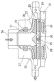
具体例として、本発明者によって図4に示すような人工心臓用遠心ポンプが発明され、特許第2807786号として特許されている(特開平10−33664号)。この人工心臓ポンプによると、図4に示すように遠心式インペラ22を2つの軸受26−28及び25−30で支えている。ケーシング27の下部にはインペラ駆動装置31を設け、その内部で磁石33が回転することにより、インペラ内蔵の磁石群24を回転駆動している。それによりケーシング上部に形成した流入口34から血液が流入し、ケーシングの下部周囲に設けた流出口からこれを吐出することができるようになっている。なお、上記のような磁気カップリングによりインペラを回転する手段として、可動部分33を電磁石群に置換したダイレクトドライブ方式の駆動装置を採用したものも開発されている。
【0006】
【発明が解決しようとする課題】
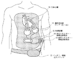
上記のようなポンプの開発によって、連続流型の人工心臓ポンプの実用化が間近であり、その際には例えば図3に示すような状態で体内に埋め込んで使用される。即ち、生体心臓10に対して前記のような左右2個の連続流血液ポンプ11の流入口及び吐出口を生体心臓10に連結し、生体心臓の作動と並列に各ポンプで血液を送る作動をなすように結合する。このような連続流血液ポンプ11は、図示実施例においては患者が着帯して所持しているバッテリ・情報入出力ユニット12から腹部外に付着させた体外エネルギー・情報送受信部13にエネルギー及び各種情報を送り、腹部内に埋設した体内エネルギー・情報送受信部14でこれを電磁力及び電磁信号として取り込み、生体内に埋め込まれた制御装置15によってその駆動電力を調節しつつ前記各血液ポンプを駆動する。なお、本発明においては後述するように、制御装置15によって各人工心臓ポンプの作動状態を検出し、そのデータを前記エネルギー・情報送受信系を介して外部に取り出すことが可能となる。
【0007】
連続流型の人工心臓ポンプを実際に上記のような形態で使用するに際しては、このポンプを体内に埋め込んで使用するため、頻繁に取り出すことは困難であり、一度これを埋め込んだ後はできる限り取り出すことがないように長期間このまま使用することが好ましい。また、万が一異常が発生したときには、決定的な破損等に至る前に修理を行う必要があり、そのためこのようなポンプの使用に際して的確なメンテナンスが必要であり、また、万が一ポンプに故障が発生したときにはこれを直ちに取り出して修理し、或いは交換を行う必要がある。
【0008】
人工心臓用ポンプの不調、或いは故障等の異常としては、ポンプ機構部分の機械的な破損の他、例えば軸受部分を初めとするポンプ内部に血流のよどみが発生し、血液凝固が生じてこれが拡大し、ポンプの機能に大きな影響を及ぼし、これがポンプから剥がれて流出するときには重要な血管を閉塞することも考えられる。したがってこれらのポンプの不調、或いは故障等の異常をできる限り早く、正確に検出することが重要であり、その対策が必要となる。
【0009】
その対策の一つとして、この人工心臓を使用している人の体調を、例えば血圧、脈拍、血流中の各種成分の分析を行ってそのデータを常時計測し、ポンプの異常の発生の結果変化すると思われる要素を精密に監視することによってポンプの不調、或いは故障等の異常を検出することが考えられる。
【0010】
しかしながら、上記のような利用者の体調を種々の手段で計測するものにおいては、その計測値の変化がポンプの作動不良によるものか、利用者本人の他の要素によるものかを正確に検出する技術は未だ確立していない。
【0011】
したがって、本発明は人工心臓用ポンプの不調、或いは故障等の異常を正確に、かつ素早く検出することができるようにした人工心臓用ポンプの異常判定方法及び異常判定装置を提供することを目的としている。
【0012】
【課題を解決するための手段】
本発明は、上記課題を解決するため、人工心臓用ポンプの回転数、吐出流量、圧力上昇、及び消費電力を予め検出して回転数毎の圧力−流量特性データ、及び回転数毎の電力−流量特性データを取得し、生体に接続し作動中の前記人工心臓用ポンプの回転数、吐出流量、圧力上昇、及び消費電力を検出して前記記憶した特性データと比較し、前記回転数毎の圧力−流量特性データと所定の範囲内で一致していないと判別され、且つ前記回転数毎の電力−流量特性データと所定の範囲内で一致していると判別されたとき、作動中の前記人工心臓用ポンプに幾何学的形状異常が発生したものと判定し、前記回転数毎の電力−流量特性データと所定の範囲内で一致していると判別され、且つ前記回転数毎の電力−流量特性データと所定の範囲内で一致していないと判別されたとき、作動中の前記人工心臓用ポンプ内で血液異常が発生したものと判定することを特徴とする人工心臓用ポンプの異常判定方法としたものである。
【0015】
また、請求項2に係る発明は、人工心臓用ポンプの回転数、吐出流量、圧力上昇、及び消費電力を予め検出して回転数毎の圧力−流量特性データ、及び回転数毎の電力−流量特性データを取得し記憶する記憶手段と、生体に接続し作動中の前記人工心臓用ポンプの回転数、吐出流量、圧力上昇、及び消費電力を検出する各センサと、前記各センサの検出値と前記記憶した特性データと比較する比較判別手段とを備え、前記比較判別手段は、前記回転数毎の圧力−流量特性データと所定の範囲内で一致していないと判別され、且つ前記回転数毎の電力−流量特性データと所定の範囲内で一致していると判別されたとき、作動中の前記人工心臓用ポンプに幾何学的形状異常が発生したものと判定し、前記回転数毎の電力−流量特性データと所定の範囲内で一致していると判別され、且つ前記回転数毎の電力−流量特性データと所定の範囲内で一致していないと判別されたとき、作動中の前記人工心臓用ポンプ内で血液異常が発生したものと判定することを特徴とする人工心臓用ポンプの異常判定装置としたものである。
【0018】
【発明の実施の形態】
本発明の実施例を図面に沿って説明する。図1は本発明による人工心臓用遠心ポンプの一実施例における駆動特性を示すグラフの例であり、(a)はこのポンプの圧力上昇(kPa)と流量(L/min)の関係を、ポンプの回転数毎に表した圧力−流量曲線であり、(b)はこのポンプの作動による吐出血液の消費電力(w)と流量(L/min)の関係を、ポンプの回転数毎に表した消費電力−流量曲線である。
【0019】
これらのグラフはこの人工心臓用ポンプを体内に埋め込む前に予め各回転数に設定して、血液または血液と同じ性状を有する液体を用い、ポンプから吐出される流体の流量を0から徐々に上昇させ、各流量における吐出流体の圧力上昇、及びそのときの消費電力を検出することにより得られ、このデータを制御装置に記憶させておく。なお、前記消費電力の検出に際して、これをポンプに対して与えた電流を検出することによっても同様のデータを得ることができる。また、図示されたような回転数以外の回転数部分については、補完法等によりデータを補完し、実質的に全回転数に対応した上記特性のデータを得ることもできる。
【0020】
上記のようなデータを得た後、この人工心臓ポンプを図3のように体内に埋め込み使用する。このような使用中は常時制御装置15により各人工心臓用ポンプ11の作動状態を監視しており、予めポンプの吐出口内壁に圧力センサを設け、必要に応じてポンプの流入口にも同様の圧力センサを設けることにより、このポンプの圧力上昇値を得ることができる。また、流量は同様にポンプの吐出口に超音波流量計等の任意の流量計を設けておくことにより、その計測値を得ることができる。
【0021】
制御装置15ではこのような計測データを常時入力し、この実施例においてはこれを送信用データとしてエネルギー・情報送受信部13、14を介してバッテリ・情報入出力ユニット12に信号を出力する。バッテリー・情報入出力ユニット12では、予めプログラムされたデータ監視手段によりこのデータを分析し、現在作動しているポンプが前記図1に示す特性に対応しているか否かを比較して調べる。なお、このようなデータの比較に際して、例えばポンプが2000回転の時図1(a)の2000rpmの特性になるはずではあるが、測定誤差を考慮して、予め定めた許容範囲内にそのデータが入っているか否かを判別することが好ましい。
【0022】
実際の人工心臓用ポンプの使用に際して、例えば医者が患者の体調が良くないと思ったときにはその原因を探すため、一応ポンプの作動が正常であるか否か、即ち異常ではないかをチェックする必要がある。そのときにはポンプの作動状態を検出したデータと図1(a)及び(b)の特性曲線のデータと各センサの計測データとを比較し、例えば図2に示す異常判別処理によって各種の判別を行うことができる。図2に示す人工心臓用ポンプの異常判別処理に際しては、最初、作動中のポンプの計測データが前記「圧力−流量」の特性曲線にのっているか否かを判別する(ステップS1)。この判別に際しては、図示する所定の特性曲線に対して誤差の許容範囲を設定し、その範囲内に入っているか否かにより判別を行う。
【0023】
前記ステップS1の判別の結果、「圧力−流量」の特性曲線にのっていると判別されたときには、作動中のポンプの計測データが前記「消費電力−流量」の特性曲線にのっているか否かを判別する(ステップS2)。この判別に際しても前記と同様に、図示する所定の特性曲線に対して誤差の許容範囲を設定し、その範囲内に入っているか否かにより判別を行う。
【0024】
このステップS2の判別の結果、「消費電力−流量」の特性曲線にのっていると判別されたときにはポンプは正常であると判別し(ステップS3)、前記のような患者の体調の不調はポンプが原因となっているものではなく、患者の他の部分の異常、或いはポンプの接続チューブの異常等が原因であると判定する。それに対して前記ステップS2の判別の結果、「消費電力−流量」の特性曲線にのっていないと判別されたときには、現在作動中のポンプ内で、例えば血栓の形成等、血液の異常が発生していると判定する(ステップS4)。
【0025】
また、前記ステップS1において「圧力−流量」の特性曲線にのっていないと判別されたときには、作動中のポンプの計測データが前記「消費電力−流量」の特性曲線にのっているか否かを判別する(ステップS5)。この判別に際しても前記と同様に、図示する所定の特性曲線に対して誤差の許容範囲を設定し、その範囲内に入っているか否かにより判別を行う。
【0026】
前記ステップS5の判別の結果「消費電力−流量」の特性曲線にのっていると判別されたときには、現在作動中のポンプは前記ステップS1で判別したように「圧力−流量」の特性曲線にのっていないと判別されているので、ポンプに例えば羽根損傷のような幾何学的異常が発生しているものと判定する(ステップS6)。
【0027】
また、ステップS5において、「消費電力−流量」の特性曲線にのっていないと判別されたときには、前記ステップS1において「圧力−流量」の特性曲線にのっていないと判別されているので、ポンプに例えば羽根損傷のような幾何学的異常が発生しているものと判定され、更にステップS5において、「消費電力−流量」の特性曲線にのっていないと判別された結果、現在作動中のポンプ内で例えば血栓の形成等、血液の異常が発生していると判定する(ステップS7)。
【0028】
以上のような判別手法によって人工心臓用ポンプが異常であるか否か、また異常であるときにはそれが羽根の損傷等のポンプ自体の幾何学的な異常であるか否か、更にはポンプ内で血栓等が発生する等による血液異常が発生していることによるかを容易に判定することができる。
【0029】
上記実施例においては、本発明による人工心臓用ポンプの異常判定方法及び異常判定装置として、図4に示したような本発明者が先に提案した遠心ポンプを用いた例について説明したが、本発明は上記のような遠心ポンプに限らず、軸流式は回転容積型など各種の形態の羽根を備え、各種の駆動形式を採用し、更に各種の軸受構造を備えた連続流型人工心臓に適用することができる。
【0030】
【発明の効果】
本発明は以上のように構成したので、人工心臓用ポンプの不調、或いは故障等の異常を人工心臓を体内から取り出すことなく、正確に、かつ素早く検出することができる。
【図面の簡単な説明】
【図1】本発明による人工心臓用ポンプの異常判定を行う際に用いる人工心臓用ポンプの特性の例を示すグラフである。
【図2】本発明を実施する作動フロー図である。
【図3】体内に埋め込む人工心臓用ポンプの使用態様を示す模式図である。
【図4】本発明者が先に提案した人工心臓用遠心ポンプの主要部を示す断面図である。[0001]
BACKGROUND OF THE INVENTION
The present invention relates to an artificial heart pump used in place of or together with a living heart, and more particularly to a method for determining an abnormality of such an artificial heart pump and an apparatus for determining such an abnormality.
[0002]
[Prior art]
In Japan, an organ transplantation method has been implemented, and heart transplantation from brain death is possible. However, since the actual situation is a lack of donors, the only way to save the remaining patients is artificial heart. Artificial heart has been studied for a long time, and many clinical uses have been reported. The artificial heart includes an auxiliary artificial heart that can be placed in parallel without excising the living heart, and a complete replacement artificial heart that is excised and combined. In the past, most of these were air-driven types with a control device installed at the bed site, but recently, an abdomen can be implanted, and an auxiliary artificial heart that is electrically driven using a battery attached to a belt or backpack has been developed. Although current products are limited to patients with large physiques due to their size, artificial hearts that can also be used at home are being used.
[0003]
When such an artificial heart is classified from the point of the pump type, there are roughly two types, a pulsating flow type and a continuous flow type. The pulsatile flow type is a method of delivering a fixed amount of blood for each stroke, and some auxiliary artificial hearts that have advanced clinical applications have a track record of use on a yearly basis. The continuous flow type is a system in which blood is continuously sent out by a rotating mechanism, and the delivery amount is not directly related to the pump volume and is easily reduced in size, which is promising for an implantable auxiliary artificial heart. Regarding the effects of non-pulsatile flow on living bodies, some animal experiments have reported that they survive without physiological problems. However, since pulsatile flow is preferred physiologically, the continuous flow pump is being developed as an auxiliary artificial heart that leaves a living heart.
[0004]
The development of continuous flow type artificial heart is progressing in Japan, and there are individual types of continuous flow type pumps such as centrifugal type, axial flow type, rotary volume type, etc., all pump characteristics are pressure, flow rate, power, rotation It can be characterized in terms of numbers. The present invention relates to this continuous flow type artificial heart.
[0005]
As a specific example, a centrifugal pump for artificial heart as shown in FIG. 4 was invented by the present inventor and patented as Japanese Patent No. 2807786 (Japanese Patent Laid-Open No. 10-33664). According to this artificial heart pump, the
[0006]
[Problems to be solved by the invention]
With the development of the pump as described above, the continuous flow type artificial heart pump is about to be put into practical use, and in that case, for example, it is used by being implanted in the body in the state shown in FIG. That is, the inflow and discharge ports of the two continuous flow blood pumps 11 on the left and right sides of the
[0007]
When the continuous flow type artificial heart pump is actually used in the above-mentioned form, it is difficult to take out frequently because it is embedded in the body. It is preferable to use it as it is for a long time so as not to take it out. In the unlikely event that an abnormality occurs, it is necessary to carry out repairs before decisive damage, etc. Therefore, proper maintenance is required when using such a pump, and a failure has occurred in the pump. Sometimes it is necessary to take it out immediately for repair or replacement.
[0008]
Abnormalities such as malfunction or failure of the pump for artificial heart include mechanical damage of the pump mechanism part, stagnation of blood flow inside the pump including the bearing part, and blood coagulation. It can also enlarge and have a major effect on the functioning of the pump, which can also occlude important blood vessels when it detaches from the pump and flows out. Therefore, it is important to detect malfunctions or malfunctions of these pumps as quickly and accurately as possible, and countermeasures are required.
[0009]
As one of the countermeasures, the physical condition of the person using this artificial heart is analyzed, for example, blood pressure, pulse, and various components in the blood flow, and the data is constantly measured. It is conceivable to detect abnormalities such as malfunctions or malfunctions of the pump by precisely monitoring elements that may change.
[0010]
However, in the case of measuring the physical condition of the user by various means as described above, it is accurately detected whether the change in the measured value is due to malfunction of the pump or other factors of the user. Technology has not yet been established.
[0011]
SUMMARY OF THE INVENTION Accordingly, an object of the present invention is to provide an abnormality determination method and an abnormality determination device for an artificial heart pump that can accurately and quickly detect malfunctions such as malfunction or failure of the artificial heart pump. Yes.
[0012]
[Means for Solving the Problems]
In order to solve the above-mentioned problems, the present invention detects in advance the rotation speed, discharge flow rate, pressure rise, and power consumption of an artificial heart pump, pressure-flow rate characteristic data for each rotation speed, and power for each rotation speed- The flow rate characteristic data is acquired, and the rotation speed, discharge flow rate, pressure increase, and power consumption of the artificial heart pump connected to the living body and operating are detected and compared with the stored characteristic data. When it is determined that the pressure-flow rate characteristic data does not match within a predetermined range , and the power-flow rate characteristic data for each rotation speed is determined to match within a predetermined range, It is determined that a geometrical shape abnormality has occurred in the artificial heart pump, and it is determined that the power-flow rate characteristic data for each rotation speed matches the predetermined range , and the power for each rotation speed- Within the specified range with the flow characteristics data If it is judged to not is obtained by a method of determining a failure of an artificial heart pump, characterized in that determined that blood abnormality occurs in the artificial heart pump in operation.
[0015]
In the invention according to
[0018]
DETAILED DESCRIPTION OF THE INVENTION
Embodiments of the present invention will be described with reference to the drawings. FIG. 1 is an example of a graph showing drive characteristics in an embodiment of an artificial heart centrifugal pump according to the present invention. FIG. 1 (a) shows the relationship between the pump pressure increase (kPa) and the flow rate (L / min). (B) represents the relationship between the power consumption (w) and the flow rate (L / min) of the discharged blood by the operation of the pump for each number of rotations of the pump. It is a power consumption-flow rate curve.
[0019]
These graphs set each rotation speed in advance before implanting this artificial heart pump into the body, and use blood or liquid having the same properties as blood, and gradually increase the flow rate of fluid discharged from the pump from 0 This is obtained by detecting the pressure rise of the discharged fluid at each flow rate and the power consumption at that time, and this data is stored in the control device. Note that similar data can be obtained by detecting the current applied to the pump when detecting the power consumption. Further, with respect to the rotational speed portion other than the rotational speed as shown in the drawing, the data can be supplemented by a complementing method or the like to obtain data having the above characteristics substantially corresponding to the total rotational speed.
[0020]
After obtaining the above data, the artificial heart pump is implanted in the body as shown in FIG. During such use, the operation state of each artificial heart pump 11 is constantly monitored by the
[0021]
The
[0022]
When using an artificial heart pump, for example, when a doctor thinks that the patient is not in good health, it is necessary to check whether the pump is operating normally, that is, to find out the cause. There is. At that time, the data for detecting the operating state of the pump, the data of the characteristic curves in FIGS. 1A and 1B, and the measurement data of each sensor are compared, and various determinations are made by, for example, the abnormality determination process shown in FIG. be able to. In the abnormality determination process of the artificial heart pump shown in FIG. 2, it is first determined whether or not the measurement data of the pump in operation is on the “pressure-flow rate” characteristic curve (step S1). In this determination, an allowable range of error is set for a predetermined characteristic curve shown in the figure, and the determination is made based on whether or not the predetermined characteristic curve is within the range.
[0023]
As a result of the determination in the step S1, if it is determined that the characteristic curve of “pressure-flow rate” is on, the measured data of the operating pump is on the characteristic curve of “power consumption-flow rate”. It is determined whether or not (step S2). In this determination as well, as described above, an allowable range of error is set for the predetermined characteristic curve shown in the figure, and the determination is made based on whether or not it is within the range.
[0024]
As a result of the determination in step S2, it is determined that the pump is normal when it is determined that it is on the characteristic curve of “power consumption-flow rate” (step S3). It is determined not to be caused by the pump but to be caused by an abnormality in another part of the patient or an abnormality in the connection tube of the pump. On the other hand, if it is determined as a result of the determination in step S2 that the characteristic curve of “power consumption-flow rate” is not on, a blood abnormality such as thrombus formation occurs in the currently operating pump. (Step S4).
[0025]
If it is determined in step S1 that the characteristic curve of “pressure-flow rate” is not on, the measurement data of the operating pump is on the characteristic curve of “power consumption-flow rate”. Is discriminated (step S5). In this determination as well, as described above, an allowable range of error is set for the predetermined characteristic curve shown in the figure, and the determination is made based on whether or not it is within the range.
[0026]
When it is determined that the characteristic curve of “power consumption-flow rate” is on the characteristic curve as a result of the determination in step S5, the currently operating pump has a characteristic curve of “pressure-flow rate” as determined in step S1. Since it is determined that it is not mounted, it is determined that a geometric abnormality such as blade damage has occurred in the pump (step S6).
[0027]
Further, when it is determined in step S5 that it is not on the “power consumption-flow rate” characteristic curve, it is determined in step S1 that it is not on the “pressure-flow rate” characteristic curve. It is determined that a geometrical abnormality such as blade damage has occurred in the pump, for example. Further, in step S5, it is determined that the pump is not on the "power consumption-flow rate" characteristic curve. It is determined that a blood abnormality such as thrombus formation has occurred in the pump (step S7).
[0028]
Whether or not the artificial heart pump is abnormal by the discrimination method as described above, and if abnormal, whether it is a geometric abnormality of the pump itself, such as blade damage, It is possible to easily determine whether a blood abnormality due to a thrombus or the like has occurred.
[0029]
In the above embodiment, the example in which the centrifugal pump previously proposed by the inventor as shown in FIG. 4 is used as the abnormality determination method and abnormality determination apparatus for the artificial heart pump according to the present invention has been described. The invention is not limited to the centrifugal pump as described above, but the axial flow type is provided with various types of blades such as a rotary displacement type, adopts various drive types, and further provides a continuous flow type artificial heart having various bearing structures. Can be applied.
[0030]
【The invention's effect】
Since the present invention is configured as described above, an abnormality such as malfunction or failure of the artificial heart pump can be detected accurately and quickly without removing the artificial heart from the body.
[Brief description of the drawings]
FIG. 1 is a graph showing an example of characteristics of an artificial heart pump used when determining an abnormality of an artificial heart pump according to the present invention.
FIG. 2 is an operation flow chart for carrying out the present invention.
FIG. 3 is a schematic view showing a usage mode of an artificial heart pump implanted in a body.
FIG. 4 is a cross-sectional view showing a main part of a centrifugal pump for artificial heart previously proposed by the present inventor.
Claims (2)
生体に接続し作動中の前記人工心臓用ポンプの回転数、吐出流量、圧力上昇、及び消費電力を検出して前記記憶した特性データと比較し、
前記回転数毎の圧力−流量特性データと所定の範囲内で一致していないと判別され、且つ前記回転数毎の電力−流量特性データと所定の範囲内で一致していると判別されたとき、作動中の前記人工心臓用ポンプに幾何学的形状異常が発生したものと判定し、
前記回転数毎の電力−流量特性データと所定の範囲内で一致していると判別され、且つ前記回転数毎の電力−流量特性データと所定の範囲内で一致していないと判別されたとき、作動中の前記人工心臓用ポンプ内で血液異常が発生したものと判定することを特徴とする人工心臓用ポンプの異常判定方法。Detecting the rotation speed, discharge flow rate, pressure rise, and power consumption of the artificial heart pump in advance to obtain pressure-flow rate characteristic data for each rotation number, and power-flow rate characteristic data for each rotation number,
The rotation speed, discharge flow rate, pressure rise, and power consumption of the artificial heart pump that is connected to the living body and is operating are detected and compared with the stored characteristic data,
When it is determined that the pressure-flow rate characteristic data for each rotation number does not match within a predetermined range, and it is determined that the pressure-flow rate characteristic data for each rotation number matches within a predetermined range , Determining that a geometric abnormality has occurred in the artificial heart pump in operation,
When it is determined that the power-flow rate characteristic data for each rotation number is in agreement within a predetermined range, and it is determined that the power-flow rate characteristic data for each rotation number is not in agreement within a predetermined range An abnormality determination method for an artificial heart pump, wherein it is determined that a blood abnormality has occurred in the artificial heart pump in operation.
生体に接続し作動中の前記人工心臓用ポンプの回転数、吐出流量、圧力上昇、及び消費電力を検出する各センサと、
前記各センサの検出値と前記記憶した特性データと比較する比較判別手段とを備え、
前記比較判別手段は、前記回転数毎の圧力−流量特性データと所定の範囲内で一致していないと判別され、且つ前記回転数毎の電力−流量特性データと所定の範囲内で一致していると判別されたとき、作動中の前記人工心臓用ポンプに幾何学的形状異常が発生したものと判定し、
前記回転数毎の電力−流量特性データと所定の範囲内で一致していると判別され、且つ前記回転数毎の電力−流量特性データと所定の範囲内で一致していないと判別されたとき、作動中の前記人工心臓用ポンプ内で血液異常が発生したものと判定することを特徴とする人工心臓用ポンプの異常判定装置。Storage means for detecting the rotational speed, discharge flow rate, pressure rise, and power consumption of the artificial heart pump in advance to acquire and store pressure-flow characteristic data for each rotational speed and power-flow characteristic data for each rotational speed; ,
Each sensor that detects the rotation speed, discharge flow rate, pressure increase, and power consumption of the artificial heart pump connected to the living body and operating;
Comparing and determining means for comparing the detected value of each sensor with the stored characteristic data,
The comparison determination means determines that the pressure-flow rate characteristic data for each rotation speed does not match within a predetermined range, and matches the power-flow rate characteristic data for each rotation speed within a predetermined range. When it is determined that there is a geometric abnormality in the operating artificial heart pump,
When it is determined that the power-flow rate characteristic data for each rotation number is in agreement within a predetermined range, and it is determined that the power-flow rate characteristic data for each rotation number is not in agreement within a predetermined range An abnormality determination device for an artificial heart pump, wherein it is determined that a blood abnormality has occurred in the artificial heart pump in operation.
Priority Applications (1)
| Application Number | Priority Date | Filing Date | Title |
|---|---|---|---|
| JP2001206189A JP3882069B2 (en) | 2001-07-06 | 2001-07-06 | Abnormality determination method and abnormality determination device for artificial heart pump |
Applications Claiming Priority (1)
| Application Number | Priority Date | Filing Date | Title |
|---|---|---|---|
| JP2001206189A JP3882069B2 (en) | 2001-07-06 | 2001-07-06 | Abnormality determination method and abnormality determination device for artificial heart pump |
Publications (2)
| Publication Number | Publication Date |
|---|---|
| JP2003019197A JP2003019197A (en) | 2003-01-21 |
| JP3882069B2 true JP3882069B2 (en) | 2007-02-14 |
Family
ID=19042363
Family Applications (1)
| Application Number | Title | Priority Date | Filing Date |
|---|---|---|---|
| JP2001206189A Expired - Lifetime JP3882069B2 (en) | 2001-07-06 | 2001-07-06 | Abnormality determination method and abnormality determination device for artificial heart pump |
Country Status (1)
| Country | Link |
|---|---|
| JP (1) | JP3882069B2 (en) |
Families Citing this family (14)
| Publication number | Priority date | Publication date | Assignee | Title |
|---|---|---|---|---|
| JP2005066013A (en) * | 2003-08-25 | 2005-03-17 | Miwatec:Kk | Method and apparatus for controlling continuous flow rotary blood pump |
| DE102007007198A1 (en) * | 2007-02-09 | 2008-08-14 | Maquet Cardiopulmonary Ag | Method and device for monitoring and optimizing a blood circulation caused by a pump |
| DE102009060668A1 (en) * | 2009-12-28 | 2011-06-30 | Fresenius Medical Care Deutschland GmbH, 61352 | Apparatus and method for monitoring extracorporeal blood treatment |
| EP2585129B8 (en) * | 2010-06-22 | 2017-07-12 | Tc1 Llc | Fluid delivery system and method for monitoring fluid delivery system |
| JP5763940B2 (en) * | 2011-03-22 | 2015-08-12 | 京セラメディカル株式会社 | External motor system for centrifugal blood pump |
| JP5962894B2 (en) * | 2012-03-09 | 2016-08-03 | 国立大学法人広島大学 | Blood flow control device and extracorporeal circulation device |
| KR101524052B1 (en) * | 2014-09-29 | 2015-05-29 | 남택무 | Pump unit and emergency operation method thereof |
| JP2020033871A (en) * | 2017-01-05 | 2020-03-05 | 日本電産テクノモータ株式会社 | Pump device and method for controlling pump device |
| DE102018201030A1 (en) | 2018-01-24 | 2019-07-25 | Kardion Gmbh | Magnetic coupling element with magnetic bearing function |
| DE102018207611A1 (en) | 2018-05-16 | 2019-11-21 | Kardion Gmbh | Rotor bearing system |
| DE102018208541A1 (en) | 2018-05-30 | 2019-12-05 | Kardion Gmbh | Axial pump for a cardiac assist system and method of making an axial pump for a cardiac assist system |
| DE102018210076A1 (en) * | 2018-06-21 | 2019-12-24 | Kardion Gmbh | Method and device for detecting a state of wear of a cardiac support system, method and device for operating a cardiac support system and cardiac support system |
| DE102018212153A1 (en) | 2018-07-20 | 2020-01-23 | Kardion Gmbh | Inlet line for a pump unit of a cardiac support system, cardiac support system and method for producing an inlet line for a pump unit of a cardiac support system |
| DE102020102474A1 (en) | 2020-01-31 | 2021-08-05 | Kardion Gmbh | Pump for conveying a fluid and method for manufacturing a pump |
-
2001
- 2001-07-06 JP JP2001206189A patent/JP3882069B2/en not_active Expired - Lifetime
Also Published As
| Publication number | Publication date |
|---|---|
| JP2003019197A (en) | 2003-01-21 |
Similar Documents
| Publication | Publication Date | Title |
|---|---|---|
| EP3600478B1 (en) | Pressure sensing ventricular assist devices | |
| JP3882069B2 (en) | Abnormality determination method and abnormality determination device for artificial heart pump | |
| US6176822B1 (en) | Intracardiac blood pump | |
| JP4179634B2 (en) | Intracardiac blood pump | |
| JP3534419B2 (en) | Blood flow circulating assist device using continuous flow blood pump and diagnostic device for blood flow circulating state of living body | |
| EP2988795B1 (en) | Biomedical apparatus for pumping blood of a human or an animal patient through a secondary intra- or extracorporeal blood circuit | |
| EP3233152B1 (en) | System and method for peritoneal dialysis | |
| JP4769937B2 (en) | Centrifugal pump flow rate and head measurement device, and circulating state evaluation device for pulsating circulation system | |
| EP2945661B1 (en) | Backflow detection for centrifugal blood pump | |
| JP4761134B2 (en) | Mass flow meter | |
| EP3013383B1 (en) | Monitoring of a cardiac assist device | |
| US10420870B2 (en) | Heart rate determination based on VAD current waveform | |
| JP2005192687A (en) | Indirect measuring method for pressure, flow rate and natural cardiac output in partial assist using rotating artificial heart pump | |
| WO2024131262A1 (en) | Method and device for measuring blood pressure at outlet of blood pump | |
| US20040133061A1 (en) | Methods for detecting an abnormal condition of a blood pump system | |
| US20230390468A1 (en) | Peritoneal dialysis system including manifold assembly and peristaltic pump | |
| JP2004073875A (en) | Blood flow circulation auxiliary device using continuous flow blood pump, and diagnostic apparatus for examining blood flow circulation state of living body | |
| JP2005080982A (en) | Method of detecting abnormality in blood pump system | |
| Kosaka et al. | Noninvasive blood-flow meter using a curved cannula with zero compensation for an axial flow blood pump |
Legal Events
| Date | Code | Title | Description |
|---|---|---|---|
| A131 | Notification of reasons for refusal |
Free format text: JAPANESE INTERMEDIATE CODE: A131 Effective date: 20060207 |
|
| A521 | Written amendment |
Free format text: JAPANESE INTERMEDIATE CODE: A523 Effective date: 20060406 |
|
| A131 | Notification of reasons for refusal |
Free format text: JAPANESE INTERMEDIATE CODE: A131 Effective date: 20060801 |
|
| A521 | Written amendment |
Free format text: JAPANESE INTERMEDIATE CODE: A523 Effective date: 20060920 |
|
| TRDD | Decision of grant or rejection written | ||
| A01 | Written decision to grant a patent or to grant a registration (utility model) |
Free format text: JAPANESE INTERMEDIATE CODE: A01 Effective date: 20061024 |
|
| R150 | Certificate of patent or registration of utility model |
Ref document number: 3882069 Country of ref document: JP Free format text: JAPANESE INTERMEDIATE CODE: R150 Free format text: JAPANESE INTERMEDIATE CODE: R150 |
|
| S533 | Written request for registration of change of name |
Free format text: JAPANESE INTERMEDIATE CODE: R313533 |
|
| R350 | Written notification of registration of transfer |
Free format text: JAPANESE INTERMEDIATE CODE: R350 |
|
| EXPY | Cancellation because of completion of term |