JP3877397B2 - Sheet transfer device - Google Patents
Sheet transfer device Download PDFInfo
- Publication number
- JP3877397B2 JP3877397B2 JP30881097A JP30881097A JP3877397B2 JP 3877397 B2 JP3877397 B2 JP 3877397B2 JP 30881097 A JP30881097 A JP 30881097A JP 30881097 A JP30881097 A JP 30881097A JP 3877397 B2 JP3877397 B2 JP 3877397B2
- Authority
- JP
- Japan
- Prior art keywords
- frame
- sheet
- reversing
- state
- cover
- Prior art date
- Legal status (The legal status is an assumption and is not a legal conclusion. Google has not performed a legal analysis and makes no representation as to the accuracy of the status listed.)
- Expired - Fee Related
Links
- 239000000123 paper Substances 0.000 description 4
- 239000000463 material Substances 0.000 description 2
- 125000002066 L-histidyl group Chemical group [H]N1C([H])=NC(C([H])([H])[C@](C(=O)[*])([H])N([H])[H])=C1[H] 0.000 description 1
- 238000007599 discharging Methods 0.000 description 1
- 230000000694 effects Effects 0.000 description 1
- 238000012840 feeding operation Methods 0.000 description 1
- 238000012423 maintenance Methods 0.000 description 1
- 239000002184 metal Substances 0.000 description 1
- 229920003002 synthetic resin Polymers 0.000 description 1
- 239000000057 synthetic resin Substances 0.000 description 1
- 238000011144 upstream manufacturing Methods 0.000 description 1
Images


Landscapes
- Registering Or Overturning Sheets (AREA)
- Sheets, Magazines, And Separation Thereof (AREA)
Description
【0001】
【発明の属する技術分野】
この発明は、シート加工機の給紙ホッパに段ボールシート等のシートを連続して供給する給紙装置等のシート移送装置に関するものである。
【0002】
【従来の技術】
一般に、印刷機等のシート加工機に設けられた給紙ホッパに対する段ボールシート等のシートの供給には、シートを連続して供給することができる給紙装置が用いられる。
【0003】
上記給紙装置として、特公昭58−56694号公報および特開昭63−22437号公報に記載されたものが従来から知られている。
【0004】
上記給紙装置においては、機台の両側に設けられた一対のサイドフレーム間にシート反転装置を設けている。シート反転装置は、上記サイドフレームに揺動自在に支持された一対の反転アームを有し、その反転アームに対して交差方向に張り出すテーブルを反転アームの長さ方向に移動自在に支持している。
【0005】
上記給紙装置は、積み重ねられた多数のシートをテーブルで支持したのち、反転アームを水平方向に揺動させて各シートを側縁が下側となる立てかけた状態に姿勢を変更した後、そのシートを前倒し、あるいは後倒して先頭のシートから順に前方に搬送させるようにしている。
【0006】
【発明が解決しようとする課題】
ところで、上記給紙装置においては、装置の小型化を図った上で、長いシートであっても移送し、加工処理できるよう、機台のサイドフレーム間の間隔を長いシートの長さより短かくして、サイドフレームの後方に張り出すテーブルによって積み重ねられたシートを受け入れるようにしている。
【0007】
従って、長いシートの場合、シートの両側部それぞれが一対のサイドフレームからはみ出した状態となる。
【0008】
このため、サイドフレームの高さは、長いシートを水平状態から立てかけた状態へ姿勢を変更する際、サイドフレームが邪魔とならないようにするため、その高さ寸法を低く抑える必要が生じ、その高さは、シートが供給される給紙ホッパとの関係から1m程度とされている。
【0009】
上記のように、給紙装置のサイドフレームは低く、運転中に作業者は腰を折り曲げることによってサイドフレームと起立状態の反転アームとの間に身をのり出したり、そこへ転倒したりするおそれがある。また、そこへ身をのり出して落ちたシートを取り除こうとしたり、メンテナンスを行なったりしようとするおそれがある。
【0010】
このとき、シート反転装置の反転アームが伏倒してくると、その反転アームとサイドフレーム間に上半身や手が挟まれる危険があり、安全性の向上を図るうえにおいて改善すべき点が残されている。
【0011】
特公昭57−16058号公報においては、水平な状態で搬送されてくるシート束を人手によってシート反転装置上に立てかけ、そのシート反転装置上に複数のシート束を立てかけたのち、シート反転装置を起立させてシート束を積み重ね状態とし、その状態でシート反転装置から積み重ねシートを取り出すようにしたボード積上げ装置が記載されている。
【0012】
上記ボード積上げ装置においてもシート反転装置を揺動させるため、上記給紙装置の場合と同様に機台とシート反転装置とで体の一部が挟まれる危険がある。
【0013】
この発明の課題は、シート反転装置を有する給紙装置やボード積上げ装置等のシート移送装置の安全性の向上を図ることである。
【0014】
【課題を解決するための手段】
上記の課題を解決するために、この発明においては、機台に設けられた一対のサイドフレーム間に、水平な状態と一側縁が下となる立てかけた状態との間でシートの姿勢を変更するシート反転装置を設け、そのシート反転装置が前記サイドフレームに揺動自在に支持され、起立状態において上部が前記サイドフレーム上に張り出す反転枠と、その反転枠と交差し、反転枠の一端部から他端部に向けて移動自在に設けられたテーブルとを有し、そのテーブル上に送りこまれた山積みシートを反転枠の水平方向への揺動により一側縁が下となる立てかけた状態としてテーブルの移動により前方に搬送するようにしたシート移送装置において、前記サイドフレームと前記反転枠との間に、その反転枠の起立方向への揺動により、その反転枠で引き上げられてサイドフレーム上で扇形に展開するカバーを設けた構成を採用している。
【0015】
ここで、カバーは、前記反転枠の揺動中心軸に一端部が回動自在に支持された複数の帯板を有し、各帯板に上記揺動中心軸を中心とする弧状の長孔を半径方向に位置をずらして設け、各長孔に挿入されるガイドピンを隣接する帯板に取付けた構成のものであってもよい。
【0016】
上記のように構成すれば、シート反転装置の反転枠が起立する方向にその反転枠を揺動させると、カバーが扇形に展開し、そのカバーによって反転枠の上部とサイドフレーム間を閉塞することができるため、サイドフレーム上から装置内に身をのり出すことを防止することができ、装置の安全性の向上を図ることができる。
【0017】
【発明の実施の形態】
以上、この発明の実施の形態を図面に基づいて説明する。図は、シート移送装置として、給紙装置を示す。
【0018】
図1乃至図3に示すように、機台1の両側に設けられたサイドフレーム2間の後部にはシート反転装置10が設けられている。
【0019】
シート反転装置10は反転枠11と、その反転枠11に対して交差状に設けられたテーブル12とを有し、上記反転枠11は一対の反転アーム13間に対向一対のレール14の複数を間隔をおいて平行に設けている。
【0020】
反転枠11は、サイドフレーム2に支持された軸15を中心として揺動自在に支持され、上記サイドフレーム2に支持されたシリンダ16の作動によって垂直の状態から上端が少し前かがみに傾斜する状態と略水平の状態との間で揺動される。
【0021】
一対の反転アーム13の両端部間にはスプロケット軸17a、17bが回転自在に支持され、各スプロケット軸17a、17bに複数のスプロケット18が取付けられている。反転枠11の両端方向で対向する上記スプロケット18間にはチェーン19がかけ渡され、各チェーン19は対向一対のレール14間に配置されている。
【0022】
チェーン19は、反転枠11に支持されたモータ20の駆動によって移動される。このチェーン19には複数の覆板21が取付けられ、その覆板21の表面はレール14の表面より僅かに突出している。
【0023】
テーブル12は、前記チェーン19に連結され、対向一対のレール14に沿って移動自在に支持された走行体22と、その走行体22に支持された軸23を中心にして揺動自在に支持されたシートアーム24とから成り、上記シートアーム24は、走行体22に支持されてエアの給排により伸縮するベローズ25によって揺動される。
【0024】
前記反転枠11において、対向一対の組となるレール14の隣接部間には板状態のサポート26が設けられている。このサポート26は、シリンダ27の作動によってスプロケット軸17bを中心として揺動される。
【0025】
機台1のサイドフレーム2の外側にはカバー30が設けられている。
カバー30は、反転枠11の揺動中心となる軸15に一端部が回動自在に支持された複数の帯板31から成る。帯板31は合成樹脂や金属等の硬質の材料から成り、その各帯板31に上記軸15を中心とする円弧状の長孔32が半径方向に位置をずらして設けられている。また、帯板31には、図4に示すように、隣接する帯板31の長孔32と対向する位置に段付きのピン孔33が設けられ、各ピン孔33に挿入されたフランジ付きのガイドピン34が隣接する帯板31の長孔32に挿入されて抜け止めされている。
【0026】
ガイドピン34の抜け止めに際し、ここでは、長孔32を段付きとし、その幅寸法の大きい長孔部32aにワッシャ35を挿入し、このワッシャ35に挿入したビス36をガイドピン34の先端面に形成されたねじ孔37にねじ込んでガイドピン34の先端面にワッシャ35を固定しており、ビス36の頭部表面およびガイドピン34のフランジ34aの表面は帯板32の表面から没入された状態に保持されている。
【0027】
上記の構成から成るカバー30は、サイドフレーム2と反転枠11との間に形成された間隔が小さく、その間隔内にカバー30を組込むことができないので、図3および図6に示すように、サイドフレーム2の外部に設けられる。このとき、サイドフレーム2および反転枠11の外側面にカバー取付枠40、41を取付け、一方のカバー取付枠40にカバー30の一側に位置する帯板31を連結し、他方のカバー取付枠41にカバー30の他側に位置する帯板31を連結する。
【0028】
一方、サイドフレーム2と反転枠11の間にカバー30を組込み可能な間隔がある場合は、図7に示すように、その空間内にカバー30を組込み、一側の帯板31を反転枠11に、他側の帯板31をサイドフレーム2にそれぞれ連結する。
【0029】
前記サイドフレーム2間の前側部にはコンベヤフレーム50の後端部が配置され、そのコンベヤフレーム50は昇降用シリンダ51の作動によってサイドフレーム2に支持された軸52を中心に揺動される。
【0030】
コンベヤフレーム50には第1搬送コンベヤ53と、第2搬送コンベヤ54が設けられている。第1搬送コンベヤ53の上流側にはシート反転装置10と第1搬送コンベヤ53との間でシートSの受け渡しを行なう受渡しコンベヤ55が設けられている。
【0031】
実施の形態で示す給紙装置は上記の構造から成り、給紙に際しては、反転枠揺動用シリンダ16の作動により反転枠11を起立方向に揺動させ、下降停止位置に保持されたテーブル12のシートアーム24上に積み重ねられた山積みシートS0 を送り込む。
【0032】
このとき、サポート26は垂直状態に保持しておき、そのサポート26によってテーブル12上に送り込まれる山積みシートS0 の前側部を支持する。
【0033】
山積みシートS0 がテーブル12上に載置されると、反転枠揺動用シリンダ16の作動により、反転枠11が水平方向に向けて揺動され、その揺動によって山積みシートS0 の前側部がサポート26で受けられる。
【0034】
サポート26は山積みシートS0 の前側部を受けると、サポート揺動用シリンダ27の作用によって反転枠11に向けて揺動される。サポート26がレール14の対向部間に完全に納まる位置まで揺動して停止すると、山積みシートS0 の一側部が覆板21によって受けられる。
【0035】
図5に示すように、反転枠11が略水平となる位置まで揺動して停止すると、山積みシートS0 は上端が後方に倒れる傾斜状に保持される。その後、ベローズ25の伸長によりシートアーム24が揺動して山積みシートS0 を前倒しの状態とする。その後、チェーン19が移動し、チェーン19に取付けられた覆板21およびシートアーム24の移動により山積みシートS0 は先頭のシートSから順に前方の受渡しコンベヤ55に送られ、第1搬送コンベヤ53および第2搬送コンベヤ54によってさらに前方に搬送される。
【0036】
山積みシートS0 の全体が反転枠11上から送り出されると、反転枠11を起立方向に揺動させ、その反転枠11を前かがみに傾斜する起立状態に戻したのち、サポート26を垂直方向に揺動させて次の山積みシートS0 の受け入れの準備をする。
【0037】
上記のような給紙作業において、略水平な状態とされた反転枠11を前かがみに傾斜する起立状態に戻すと、複数の帯板31は、反転枠11側の帯板31から順に引き上げられる。
【0038】
このため、カバー30はサイドフレーム2上において扇形に展開し、そのカバー30によってサイドフレーム2と反転枠11の上部間は閉塞されることになり、給紙装置内への作業者の侵入を防止し、安全性の向上を図ることができる。
【0039】
上記カバー30は、反転枠11を水平方向に揺動させたとき、図6および図7に示すように、扁平な状態に折畳まれる。
【0040】
なお、図5の鎖線で示すように、反転枠11の後端部両側に扇形の板体60を取付け、上記反転枠11を略水平としたとき、その板体60によって反転枠11の後端部下方を覆うようにすることによって、反転枠11の後端部下方への作業者の侵入を防止することができるため、安全性をより向上させることができる。
【0041】
実施の形態において示したカバー30のように、複数の帯板31が硬質の材料から成り、これらが扇形に展開可能に連結したものが作業者の侵入防止の点ではより効果的であるが、カバー30はこれに限定されるものではない。例えば、扇形に展開可能な蛇腹であってもよく、あるいは、展開状態において扇形となるフレキシブルなシートであってもよい。
【0042】
また、実施の形態では、シート移送装置として給紙装置を例にとって説明したが、シート移送装置はこれに限定されず、特公昭57−16058号公報に記載されたボード積上げ装置であってもよい。
【0043】
【発明の効果】
以上のように、この発明においては、サイドフレームに揺動自在に支持された反転枠を起立方向に揺動させると、カバーがサイドフレーム上で扇形に展開して、サイドフレームと反転枠の上部間を閉塞するため、作業者がサイドフレーム上から装置内に身を乗り出したり、転倒するのを防止することができ、安全性の向上を図ることができる。
【図面の簡単な説明】
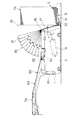
【図1】この発明に係るシート移送装置の実施の形態を示す正面図
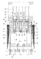
【図2】同上のシート反転装置部分を拡大して示す一部切欠正面図
【図3】同上の平面図
【図4】(I)は同上のカバーにおける帯板の連結部を示す断面図、(II)は分解斜視図
【図5】同上の山積みシートの反転状態を示す正面図
【図6】図3のVI−VI線に沿った断面図
【図7】同上カバーの他の取付け例を示す断面図
【符号の説明】
1 機台
2 サイドフレーム
10 シート反転装置
11 反転枠
12 テーブル
30 カバー
31 帯板
34 ガイドピン[0001]
BACKGROUND OF THE INVENTION
The present invention relates to a sheet transfer apparatus such as a sheet feeding apparatus that continuously supplies sheets such as cardboard sheets to a sheet feeding hopper of a sheet processing machine.
[0002]
[Prior art]
In general, a sheet feeding device capable of continuously supplying sheets is used to supply a sheet such as a corrugated cardboard sheet to a sheet feeding hopper provided in a sheet processing machine such as a printing press.
[0003]
As the paper feeding device, those described in Japanese Patent Publication No. 58-56694 and Japanese Patent Laid-Open No. 63-22437 are conventionally known.
[0004]
In the sheet feeding device, a sheet reversing device is provided between a pair of side frames provided on both sides of the machine base. The sheet reversing device has a pair of reversing arms supported by the side frames so as to be swingable, and supports a table extending in a crossing direction with respect to the reversing arms so as to be movable in the length direction of the reversing arms. Yes.
[0005]
The sheet feeding device supports a large number of stacked sheets on a table, swings the reversing arm in the horizontal direction, and changes the posture of each sheet to a leaning state with the side edge on the lower side. The sheet is moved forward or backward and conveyed forward from the first sheet.
[0006]
[Problems to be solved by the invention]
By the way, in the above-described paper feeding device, the size of the device is reduced, and even a long sheet can be transferred and processed so that the interval between the side frames of the machine base is shorter than the length of the long sheet, The stacked sheets are received by a table projecting behind the side frame.
[0007]
Therefore, in the case of a long sheet, both side portions of the sheet protrude from the pair of side frames.
[0008]
For this reason, the height of the side frame needs to be kept low so that the side frame does not get in the way when changing the posture of the long sheet from the horizontal state to the state of leaning. This is set to about 1 m from the relationship with the sheet feeding hopper to which the sheet is supplied.
[0009]
As described above, the side frame of the paper feeder is low, and an operator may bend his / her hips during operation, so that he / she may stick out between the side frame and the inverted arm in the standing state, or may fall over there. There is. Further, there is a risk of trying to remove the sheet that has fallen out of it or to perform maintenance.
[0010]
At this time, if the reversing arm of the sheet reversing device falls down, there is a risk that the upper body and hands will be caught between the reversing arm and the side frame, and there are points to be improved in order to improve safety. Yes.
[0011]
In Japanese Examined Patent Publication No. 57-16058, a sheet bundle conveyed in a horizontal state is manually leaned on a sheet reversing device, and a plurality of sheet bundles are leaned on the sheet reversing device, and then the sheet reversing device is erected. A board stacking device is described in which the sheet bundle is put into a stacked state and the stacked sheets are taken out from the sheet reversing device in that state.
[0012]
Also in the board stacking device, since the sheet inverting device is swung, there is a risk that a part of the body is caught between the machine base and the sheet inverting device as in the case of the sheet feeding device.
[0013]
An object of the present invention is to improve the safety of a sheet transfer device such as a sheet feeding device or a board stacking device having a sheet reversing device.
[0014]
[Means for Solving the Problems]
In order to solve the above problems, in the present invention, the posture of the seat is changed between a pair of side frames provided on the machine base between a horizontal state and a leaning state where one side edge is down. A sheet reversing device that is swingably supported by the side frame, and in an upright state, a reversing frame in which an upper portion projects on the side frame, intersects the reversing frame, and is one end of the reversing frame. state part possess a table provided to be movable toward the other end portion from one side edge by swinging in the horizontal direction of the reversing frame a pile sheet fed on the table is leaned against the lower in the sheet transport device which is adapted to convey forward by movement of the table as, between the side frame and the inversion frame by swinging of the upright direction of the reversing frame, pulling on that inverted frame It is to employ a structure in which a cover to expand in a fan on the side frame.
[0015]
Here, the cover has a plurality of strips whose one ends are rotatably supported on the swing center axis of the reversal frame, and each strip has an arc-shaped elongated hole centering on the swing center axis. May be provided by shifting the position in the radial direction and attaching the guide pin inserted into each elongated hole to the adjacent strip.
[0016]
With the above configuration, when the reversing frame is swung in the direction in which the reversing frame of the sheet reversing device stands up, the cover expands in a fan shape, and the cover closes the upper portion of the reversing frame and the side frame. Therefore, it is possible to prevent the body from sticking into the apparatus from the side frame, and to improve the safety of the apparatus.
[0017]
DETAILED DESCRIPTION OF THE INVENTION
The embodiments of the present invention have been described with reference to the drawings. The figure shows a sheet feeding device as a sheet conveying device.
[0018]
As shown in FIGS. 1 to 3, a
[0019]
The
[0020]
The
[0021]
[0022]
The
[0023]
The table 12 is connected to the
[0024]
In the
[0025]
A
The
[0026]
In order to prevent the
[0027]
The
[0028]
On the other hand, when there is an interval in which the
[0029]
A rear end portion of the
[0030]
The
[0031]
The sheet feeding device shown in the embodiment has the above-described structure. During feeding, the reversing
[0032]
In this case,
[0033]
When the piled sheets S 0 are placed on the table 12, the reversing
[0034]
When the
[0035]
As shown in FIG. 5, when the
[0036]
When the entire pile sheet S 0 is fed from the top
[0037]
In the paper feeding operation as described above, when the reversing
[0038]
For this reason, the
[0039]
When the
[0040]
As shown by a chain line in FIG. 5, when fan-shaped
[0041]
Like the
[0042]
In the embodiment, the sheet feeding device is described as an example of the sheet feeding device. However, the sheet feeding device is not limited to this, and may be a board stacking device described in Japanese Patent Publication No. 57-16058. .
[0043]
【The invention's effect】
As described above, in the present invention, when the reversing frame that is swingably supported by the side frame is swung in the upright direction, the cover expands in a fan shape on the side frame, and the top of the side frame and the reversing frame. Since the gap is closed, it is possible to prevent the operator from getting into the apparatus from the side frame or falling down, and safety can be improved.
[Brief description of the drawings]
FIG. 1 is a front view showing an embodiment of a sheet conveying apparatus according to the present invention. FIG. 2 is a partially cutaway front view showing an enlarged portion of the sheet reversing apparatus. FIG. (I) is a cross-sectional view showing the connecting portion of the band plate in the cover, (II) is an exploded perspective view (FIG. 5) is a front view showing the inverted state of the piled sheets (FIG. 6) VI- of FIG. Sectional view along line VI [Fig. 7] Sectional view showing another example of mounting the cover same as above [Explanation of symbols]
DESCRIPTION OF
Claims (2)
Priority Applications (1)
| Application Number | Priority Date | Filing Date | Title |
|---|---|---|---|
| JP30881097A JP3877397B2 (en) | 1997-11-11 | 1997-11-11 | Sheet transfer device |
Applications Claiming Priority (1)
| Application Number | Priority Date | Filing Date | Title |
|---|---|---|---|
| JP30881097A JP3877397B2 (en) | 1997-11-11 | 1997-11-11 | Sheet transfer device |
Publications (2)
| Publication Number | Publication Date |
|---|---|
| JPH11139584A JPH11139584A (en) | 1999-05-25 |
| JP3877397B2 true JP3877397B2 (en) | 2007-02-07 |
Family
ID=17985592
Family Applications (1)
| Application Number | Title | Priority Date | Filing Date |
|---|---|---|---|
| JP30881097A Expired - Fee Related JP3877397B2 (en) | 1997-11-11 | 1997-11-11 | Sheet transfer device |
Country Status (1)
| Country | Link |
|---|---|
| JP (1) | JP3877397B2 (en) |
Families Citing this family (2)
| Publication number | Priority date | Publication date | Assignee | Title |
|---|---|---|---|---|
| JP7495856B2 (en) * | 2020-09-28 | 2024-06-05 | 日立建機株式会社 | Construction Machinery |
| JP7689504B2 (en) * | 2022-03-24 | 2025-06-06 | 日立建機株式会社 | Work Machine |
-
1997
- 1997-11-11 JP JP30881097A patent/JP3877397B2/en not_active Expired - Fee Related
Also Published As
| Publication number | Publication date |
|---|---|
| JPH11139584A (en) | 1999-05-25 |
Similar Documents
| Publication | Publication Date | Title |
|---|---|---|
| JPS58147346A (en) | Inserting device for sheet | |
| JP5421619B2 (en) | Method and apparatus for folding and loading food dough | |
| JPH01267208A (en) | Device for cleaning belt and scraper used in said device | |
| US4042234A (en) | Blank feeding machine | |
| JP3877397B2 (en) | Sheet transfer device | |
| US3575281A (en) | Suspended tray conveyor | |
| US1801906A (en) | Belt conveyer | |
| US4262897A (en) | Vertical-to-horizontal conveyor system | |
| JP2872608B2 (en) | Conveyance sheet loading device | |
| JPH06219548A (en) | Thin plate transport system | |
| JP2623626B2 (en) | Tray device | |
| US4930625A (en) | Conveyor belt dumping mechanism using horizontal idlers of varying lengths | |
| JP2002347971A (en) | Sheet feeder | |
| JP2563059B2 (en) | Transport supply device | |
| US5037369A (en) | Vertical folding stacker | |
| US2741358A (en) | Article supporting conveyor apparatus | |
| JPH02261Y2 (en) | ||
| JPH1156328A (en) | Spherical crop supply device | |
| JPS63196450A (en) | Movable tray type sorter | |
| JP2001122416A (en) | Wavy conveyor | |
| JP2910992B2 (en) | Transfer arm of sorting conveyor device and sorting conveyor device using the transfer arm | |
| JPH019796Y2 (en) | ||
| JPH06247619A (en) | Sheet folding device | |
| JPH0141719Y2 (en) | ||
| JPS6143764Y2 (en) |
Legal Events
| Date | Code | Title | Description |
|---|---|---|---|
| A621 | Written request for application examination |
Free format text: JAPANESE INTERMEDIATE CODE: A621 Effective date: 20040816 |
|
| A977 | Report on retrieval |
Free format text: JAPANESE INTERMEDIATE CODE: A971007 Effective date: 20060317 |
|
| A131 | Notification of reasons for refusal |
Free format text: JAPANESE INTERMEDIATE CODE: A131 Effective date: 20060328 |
|
| A521 | Written amendment |
Free format text: JAPANESE INTERMEDIATE CODE: A523 Effective date: 20060523 |
|
| TRDD | Decision of grant or rejection written | ||
| A01 | Written decision to grant a patent or to grant a registration (utility model) |
Free format text: JAPANESE INTERMEDIATE CODE: A01 Effective date: 20061017 |
|
| A61 | First payment of annual fees (during grant procedure) |
Free format text: JAPANESE INTERMEDIATE CODE: A61 Effective date: 20061031 |
|
| R150 | Certificate of patent or registration of utility model |
Free format text: JAPANESE INTERMEDIATE CODE: R150 |
|
| FPAY | Renewal fee payment (event date is renewal date of database) |
Free format text: PAYMENT UNTIL: 20091110 Year of fee payment: 3 |
|
| FPAY | Renewal fee payment (event date is renewal date of database) |
Free format text: PAYMENT UNTIL: 20091110 Year of fee payment: 3 |
|
| FPAY | Renewal fee payment (event date is renewal date of database) |
Free format text: PAYMENT UNTIL: 20101110 Year of fee payment: 4 |
|
| FPAY | Renewal fee payment (event date is renewal date of database) |
Free format text: PAYMENT UNTIL: 20101110 Year of fee payment: 4 |
|
| FPAY | Renewal fee payment (event date is renewal date of database) |
Free format text: PAYMENT UNTIL: 20111110 Year of fee payment: 5 |
|
| FPAY | Renewal fee payment (event date is renewal date of database) |
Free format text: PAYMENT UNTIL: 20111110 Year of fee payment: 5 |
|
| FPAY | Renewal fee payment (event date is renewal date of database) |
Free format text: PAYMENT UNTIL: 20121110 Year of fee payment: 6 |
|
| FPAY | Renewal fee payment (event date is renewal date of database) |
Free format text: PAYMENT UNTIL: 20121110 Year of fee payment: 6 |
|
| FPAY | Renewal fee payment (event date is renewal date of database) |
Free format text: PAYMENT UNTIL: 20121110 Year of fee payment: 6 |
|
| FPAY | Renewal fee payment (event date is renewal date of database) |
Free format text: PAYMENT UNTIL: 20131110 Year of fee payment: 7 |
|
| R250 | Receipt of annual fees |
Free format text: JAPANESE INTERMEDIATE CODE: R250 |
|
| R250 | Receipt of annual fees |
Free format text: JAPANESE INTERMEDIATE CODE: R250 |
|
| R250 | Receipt of annual fees |
Free format text: JAPANESE INTERMEDIATE CODE: R250 |
|
| R250 | Receipt of annual fees |
Free format text: JAPANESE INTERMEDIATE CODE: R250 |
|
| LAPS | Cancellation because of no payment of annual fees |