JP3877333B2 - Fluid pressure auxiliary power unit - Google Patents
Fluid pressure auxiliary power unit Download PDFInfo
- Publication number
- JP3877333B2 JP3877333B2 JP50291498A JP50291498A JP3877333B2 JP 3877333 B2 JP3877333 B2 JP 3877333B2 JP 50291498 A JP50291498 A JP 50291498A JP 50291498 A JP50291498 A JP 50291498A JP 3877333 B2 JP3877333 B2 JP 3877333B2
- Authority
- JP
- Japan
- Prior art keywords
- fluid pressure
- auxiliary
- frame
- power
- supported
- Prior art date
- Legal status (The legal status is an assumption and is not a legal conclusion. Google has not performed a legal analysis and makes no representation as to the accuracy of the status listed.)
- Expired - Fee Related
Links
- 239000012530 fluid Substances 0.000 title claims abstract description 69
- 239000002689 soil Substances 0.000 claims description 18
- 239000000463 material Substances 0.000 claims description 14
- 238000011084 recovery Methods 0.000 claims description 11
- 238000002485 combustion reaction Methods 0.000 claims description 10
- 238000002347 injection Methods 0.000 claims description 6
- 239000007924 injection Substances 0.000 claims description 6
- 238000010586 diagram Methods 0.000 description 9
- OKTJSMMVPCPJKN-UHFFFAOYSA-N Carbon Chemical compound [C] OKTJSMMVPCPJKN-UHFFFAOYSA-N 0.000 description 6
- 238000000034 method Methods 0.000 description 4
- 239000007788 liquid Substances 0.000 description 3
- 229910052799 carbon Inorganic materials 0.000 description 2
- 239000007789 gas Substances 0.000 description 2
- 230000002706 hydrostatic effect Effects 0.000 description 2
- 239000002364 soil amendment Substances 0.000 description 2
- 239000003516 soil conditioner Substances 0.000 description 2
- 230000001419 dependent effect Effects 0.000 description 1
- 238000009434 installation Methods 0.000 description 1
- 238000009413 insulation Methods 0.000 description 1
- 238000010008 shearing Methods 0.000 description 1
- 239000007921 spray Substances 0.000 description 1
- 238000005507 spraying Methods 0.000 description 1
Images


Classifications
-
- E—FIXED CONSTRUCTIONS
- E02—HYDRAULIC ENGINEERING; FOUNDATIONS; SOIL SHIFTING
- E02F—DREDGING; SOIL-SHIFTING
- E02F5/00—Dredgers or soil-shifting machines for special purposes
- E02F5/02—Dredgers or soil-shifting machines for special purposes for digging trenches or ditches
- E02F5/06—Dredgers or soil-shifting machines for special purposes for digging trenches or ditches with digging elements mounted on an endless chain
-
- B—PERFORMING OPERATIONS; TRANSPORTING
- B09—DISPOSAL OF SOLID WASTE; RECLAMATION OF CONTAMINATED SOIL
- B09C—RECLAMATION OF CONTAMINATED SOIL
- B09C1/00—Reclamation of contaminated soil
-
- B—PERFORMING OPERATIONS; TRANSPORTING
- B09—DISPOSAL OF SOLID WASTE; RECLAMATION OF CONTAMINATED SOIL
- B09C—RECLAMATION OF CONTAMINATED SOIL
- B09C1/00—Reclamation of contaminated soil
- B09C1/06—Reclamation of contaminated soil thermally
-
- E—FIXED CONSTRUCTIONS
- E02—HYDRAULIC ENGINEERING; FOUNDATIONS; SOIL SHIFTING
- E02F—DREDGING; SOIL-SHIFTING
- E02F3/00—Dredgers; Soil-shifting machines
- E02F3/04—Dredgers; Soil-shifting machines mechanically-driven
- E02F3/96—Dredgers; Soil-shifting machines mechanically-driven with arrangements for alternate or simultaneous use of different digging elements
- E02F3/963—Arrangements on backhoes for alternate use of different tools
-
- E—FIXED CONSTRUCTIONS
- E02—HYDRAULIC ENGINEERING; FOUNDATIONS; SOIL SHIFTING
- E02F—DREDGING; SOIL-SHIFTING
- E02F9/00—Component parts of dredgers or soil-shifting machines, not restricted to one of the kinds covered by groups E02F3/00 - E02F7/00
- E02F9/08—Superstructures; Supports for superstructures
- E02F9/0858—Arrangement of component parts installed on superstructures not otherwise provided for, e.g. electric components, fenders, air-conditioning units
- E02F9/0866—Engine compartment, e.g. heat exchangers, exhaust filters, cooling devices, silencers, mufflers, position of hydraulic pumps in the engine compartment
-
- B—PERFORMING OPERATIONS; TRANSPORTING
- B09—DISPOSAL OF SOLID WASTE; RECLAMATION OF CONTAMINATED SOIL
- B09C—RECLAMATION OF CONTAMINATED SOIL
- B09C2101/00—In situ
-
- Y—GENERAL TAGGING OF NEW TECHNOLOGICAL DEVELOPMENTS; GENERAL TAGGING OF CROSS-SECTIONAL TECHNOLOGIES SPANNING OVER SEVERAL SECTIONS OF THE IPC; TECHNICAL SUBJECTS COVERED BY FORMER USPC CROSS-REFERENCE ART COLLECTIONS [XRACs] AND DIGESTS
- Y10—TECHNICAL SUBJECTS COVERED BY FORMER USPC
- Y10S—TECHNICAL SUBJECTS COVERED BY FORMER USPC CROSS-REFERENCE ART COLLECTIONS [XRACs] AND DIGESTS
- Y10S60/00—Power plants
- Y10S60/916—Unitary construction
Landscapes
- Engineering & Computer Science (AREA)
- Mining & Mineral Resources (AREA)
- Structural Engineering (AREA)
- General Engineering & Computer Science (AREA)
- Civil Engineering (AREA)
- Environmental & Geological Engineering (AREA)
- Mechanical Engineering (AREA)
- Soil Sciences (AREA)
- Life Sciences & Earth Sciences (AREA)
- Physics & Mathematics (AREA)
- Thermal Sciences (AREA)
- Processing Of Solid Wastes (AREA)
- Fluid-Pressure Circuits (AREA)
- Supply Devices, Intensifiers, Converters, And Telemotors (AREA)
- Braking Systems And Boosters (AREA)
- Power Steering Mechanism (AREA)
- Luminescent Compositions (AREA)
- Stereo-Broadcasting Methods (AREA)
- Liquid Developers In Electrophotography (AREA)
- Auxiliary Drives, Propulsion Controls, And Safety Devices (AREA)
Abstract
Description
発明の分野
本発明は一般に加圧状態下の流体圧流体を産業用機器に供給する流体圧式補助動力装置に関するもので、更に詳細には車両に設置し、流体圧式補助動力を、車両と関連する補助機器並びに現場で作動中の付属設備に供給するようになっている流体圧式補助動力装置に関するものである。
発明の背景
一般に、地上移動装置として使用されるトラック車両にはトラック、関節アーム又は工具リフター用の、例えば油圧のような流体圧(以後、単に「油圧」という。)動力を発生出来る搭載型油圧動力システムが装備されている。その上、この搭載型油圧システムは、通常1つの工具用の単一の油圧タップにより或る限定された量の付加的油圧動力を補助装置に提供出来る。
油圧式補助装置の動力要求すなわち台数の増加に伴い、油圧動力に対する要求が搭載型システムの能力を凌駕することになる。この状態が生じると、車両又は機器の性能は劣化し、作動不能又は危険な状態になることすらあり得る。過去、これら搭載型油圧システムを要求量依存型の優先弁で改変する試みがなされた。しかしながら、これらの試みは1台以上の装置が同時に油圧動力を要求する場合、その成功が限定されていた。
本発明は、車両上に取り付ける独立式補助油圧動力装置を提供することにより補助動力に対するこのような必要性に対処しようとしている。この動力装置は、動力装置に導入される多数の付属装置と同様多数の補助装置に対して制御及び補助油圧動力を提供出来る。この補助動力装置は、車両に土壌改良システムといった要求度の高い装置が装備されている場合、最も必要とされる。
発明の要約
本発明は油圧式補助動力装置に関するものである。この動力装置は、車両上に設置し、車両と関連する油圧にて駆動される油圧駆動機器と、油圧にて駆動される油圧駆動補助装置とに対して補助的油圧動力を供給するようになっている。
この動力装置はフレームを有し、このフレームは、車両の後端部に設置して燃焼エンジンとこの燃焼エンジンにより動力を受ける油圧ポンプとを支持するようになっている。油圧溜めもフレームにより支持され、油圧流体を貯蔵し、その油圧流体を油圧ポンプに供給する。
更に、この動力装置にはフレームにより支持された補助機器プラットホームが含まれている。このプラットホームは、限定されるものではないが、流体ポンプ、送風機、流体貯蔵容器及び空気処理キャニスターを含む油圧で駆動される油圧駆動補助装置及び関連付属部品を設置する目的に使用される。
この動力装置には更に、油圧動力を動力装置の補助装置に差し向け、且つ車両と関連する補助機器に差し向ける油圧分配システムが含まれている。この分配システムは油圧ポンプから分離されるか又は油圧ポンプと併せて導入可能である。
この動力装置には更に、制御卓及びそのオペレーターに近接して車両上に設置するようになっている関連回路が含まれている。制御卓は動力装置の補助装置及び車両と関連する補助機器を制御し作動させる目的に使用される。
本発明の好適実施態様においては、動力装置は軌道駆動(track drive)掘削機、特にジョン・ディール(John Deere)製の型式690E掘削機に設置される。この掘削機は、油圧にて駆動される関節ブームを備え、このブームには、トレンチング(みぞ掘り)、ドリル又は剪断工具等の車両と関連した油圧にて駆動される油圧駆動補助機器が設置される。
油圧式補助動力装置のフレームは掘削機の後部に設置され、釣り合い重錘を保持するために掘削機に設けられたボルト孔パターンとボルトにより取り付けられる。このフレームは、釣り合い重錘背後の掘削機の後部に、又は釣り合い重錘が除去された状態で取り付けることが出来る。このフレームは、フレームに組み込まれた内サブ・フレームにより掘削機に取り付けられ、車両及び釣り合い重錘のボルトとボルト孔パターンに適合している。説明する好適実施態様は690Eジョン・ディール掘削機に取り付けられるものとするが、サブ・フレームのボルト孔パターンは他の車両に取り付け可能である。
説明する実施態様において、油圧駆動補助機器は、汚染された土を処理する土壌改良装置のトレンチ工具である。このトレンチ工具は土中に穿入し、現場の土を複数個のチェーン駆動カーバイド付き刃で掘削し、一方、土が掘削されて工具で破砕される際改良流体がこの土内に排出される。この改良流体は、限定はされるものではないが、非汚染流体又は加熱空気を含む。
トレンチ工具に近接する形態で改良流体を排出すべく改良流体噴射装置が車両に設置してある。噴射装置にはトレンチ工具の長さに沿って設けられた複数個の噴射機が含まれている。噴射機には車両により支持され、改良流体分配システムに接続された管を通じて改良流体が供給される。
説明されている実施態様における改良流体分配システムは、動力装置上に設置された油圧にて駆動される油圧駆動補助装置である。この分配システムには油圧にて駆動される静圧ポンプ及び非汚染流体を貯蔵する液体貯蔵タンクが含まれる。このポンプは流体を管を通じて噴射機に移動させる目的で設けてある。噴射機には加熱された空気を提供出来る。加熱された空気の供給源は、動力装置又は車両又はこの両者の燃焼エンジンにより発生し、断熱管を通じて噴射機に供給される排気である。
土壌改良機器には又、トレンチ工具上方で掘削機のブームに設置され、作動中に放出される土壌内又は改良流体内の揮発性材料からの蒸気放出物を回収する目的に使用される蒸気放出回収フードも含まれている。結局、動力装置の付属設備にはフードで捕獲された蒸気放出物を除去して処理する蒸気放出物回収システムが含まれている。放出物回収システムには真空圧搾空気を提供する油圧的動力を受ける送風機、励起されるカーボン・フィルター及びコンデンサー・ユニットが含まれている。真空は車両及び動力装置で支持された管を通じてフードに付加される。蒸気放出物は真空によってフードから除去され、管を通じてカーボン・フィルターとコンデンサー・ユニットに搬送される。送風機によって提供される圧搾空気は又、大気を提供して汚染材料を処理する噴射搬送システムに接続可能である。
この現場での土壌改良処理装置とその方法については、ここで参照として含まれている米国特許出願第8,287,275号及び関連ある出願に説明がされている。
【図面の簡単な説明】
図1は、本発明に従った動力装置の図である。
図2aは、釣り合い重錘が装備されている車両に取り付けられた図示の本発明に従った油圧式補助動力装置の図である。
図2bは、釣り合い重錘が装備されていない車両に取り付けた図示されている本発明に従った油圧式補助動力装置の図である。
図3は、サブ・フレームによって車両に取り付けられボルトにより締め付けられ、且つ支持部材により支持された本発明に従った動力装置の図である。
図4は、本発明に従って制御卓の図である。
図5は、図4に示され制御卓及び関連ある回路ユニットの電気回路図である。
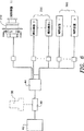
図6は、動力装置の油圧分配システムの図である。
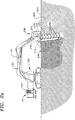
図7は、本発明の動力装置を使用している土壌改良装置の蒸気回収フードの図である。
これらの図面において同一参照番号は同一要素を表している。
発明の詳細な説明
図1は、全体的に番号10で参照されている油圧式補助動力装置を示す。動力装置10は(図3に示された)車両100上に設置するようになっており、以下に説明する如く(図2a及び図2bに示された)車両100と関連する油圧動力を受ける機器に、また油圧動力を受ける補助機器に補助油圧動力を供給する。
動力装置10は、サブ・フレーム24によって車両100の端部に設置するようになっているフレーム20を備えている。フレーム20は燃焼エンジン30、エンジンにより動力を受ける油圧ポンプ40を支持するようになっている。燃焼エンジン30はラジエーター32で冷却される。この動力装置には更に、フレーム20で支持された油圧溜め42が含まれている。溜め42は油圧流体を貯蔵し、この油圧流体を油圧ポンプ40に供給する。
動力装置10には更にフレーム20で支持された補助機器プラットホーム22が含まれている。このプラットホーム22は、これに限定されるものではないが、ポンプ50、送風機52、流体貯蔵容器54及び空気処理キャニスター56を含む、油圧にて駆動される油圧駆動補助装置及び関連付属装置を固定する目的に使用される。
動力装置10には更にフレーム20で支持された油圧分配システム44が含まれている。油圧分配システム44は油圧動力を動力装置10上の付属装置並びに車両100と関連する付属機器200に向ける。分配システム44は(図示の如く)油圧ポンプ40から分離することもでき、又(不図示の)油圧ポンプに組み込むことができる。
動力装置10には更に、制御盤420と関連の電気的センサー構成要素とを有し、オペレーターに近接した状態で車両100上に設置するようになっている制御卓400が含まれている。制御卓400は付属装置及び車両と関連した付属機器を制御し、作動させる目的に使用される。
制御卓400は制御回路60に接続され、且つ動力装置10上のフレーム20に取り付けられる。制御回路60は(図示の如く)動力装置10内に組み込むこんでも良く、又(不図示の)車両上に設置しても良い。制御卓400はワイヤリング・ハーネス62によりエンジン30、ポンプ40、油圧分配システム44及び付属装置に相互に接続される。
図2a及び図2bを参照すると、ここには本発明の好適実施態様が示されている。動力装置10は、ジョン・ディール社製の型式690E掘削機と類似した軌道駆動掘削機100に設置される。この掘削機は、油圧で駆動される関節ブーム120を備え、このブーム120には、油圧で駆動される油圧駆動補助機器200が設置してある。
油圧式補助動力装置10は、掘削機100の後部に設置され、釣り合い重錘130を保持すべく(図1に示された)ボルト孔パターン26及び掘削機100に装備されたボルト126により取り付けられる。動力装置10は(それぞれ図2b及び図2aに示された)釣り合い重錘130を備えるか又は備えていなくとも、掘削機100の後部に取り付けることが出来る。
図3を参照すると、動力装置10はサブ・フレーム24により掘削機100に取り付けられ、このサブ・フレームはボルト126及びボルト孔パターン26に適合している。サブ・フレーム24は動力装置のフレーム内に導入される。本発明の好適実施態様においては、動力装置10は好適にはジョン・ディール型式690E掘削機に取り付けられるが、サブ・フレーム24とフレーム20は(非図示の)他の車両に取り付け可能である。
図4を参照すると、制御卓400には動力装置、補助装置及び補助機器の作動を制御する電気的機械的スイッチ及びレバーを含む(図示の目的にのみ示されている)制御装置430が含まれている。制御盤420は、油圧計、温度計、電流計、電圧計及びエンジン速度計を含む機械的及び電気的指示計器440を表示する。図5は、制御卓400と関連する制御回路60の好適実施態様を示している。制御卓400はワイヤリン・ハーネス62及び関連するコネクター63によって回路60に相互に接続されている。
図2a、図2bを参照すると、説明されている実施態様における油圧駆動補助機器200は土壌改良装置である。この装置200は汚染された土壌等の汚染された材料500を処理する目的に設けてある。この装置200には所定位置の土壌をトレンチ処理する油圧的に動力を受けるトレンチ工具220が含まれている。トレンチ工具220は材料の表面520を穿入し、複数個のチェーン駆動カーバイド付き刃240により土壌を掘削する。この方法については、米国特許出願第8,287,275号及び参照として本明細書に導入されている関連ある出願で更に説明されている。
油圧駆動補助機器200には又、これも掘削機100のブーム120に設置されている蒸気放出物回収フード250が含まれている。このフードはトレンチ工具220の作動中に発生する蒸気放出物260を回収する目的に使用される。
改良流体噴射装置270はトレンチ工具220に設置してある。噴射装置270はトレンチ工具220に近接した状態で改良流体を噴出する目的に使用される。噴射装置270にはトレンチ工具220の長さに沿って設けられた複数個の噴射機280が含まれている。噴射機280には車両100で支持され、補助装置、改良流体分配システム48のいずれか一方に接続された供給管140により改良流体が供給される。改良流体には、これに限定されるものではないが、非汚染流体又は加熱空気等の液体又は気体の使用が含まれる。改良流体分配システム48は改良流体を噴射装置270に搬送し、分配する。
分配システム48には油圧的に駆動される静圧ポンプ50と液体貯蔵タンク54が含まれている。このタンク54は改良流体又は気体を貯蔵するために設けられ、ポンプ50は噴射装置270に接続された管140を通じて流体を搬送する目的に設けられる。
加うるに、補助機器には更にフード250で捕獲された蒸気放出物260を除去し、処理する蒸気放出物回収システム46が含まれている。放出物回収システム46には真空圧搾空気を提供する送風機52、活性炭・コンデンサ ユニット56が含まれている。真空は、車両100と動力装置10で支持された(不図示の)管を通じてフードに付加される。蒸気放出物260はフード250から真空によって除去され、その処理を受ける活性炭・コンデンサ ユニット56内へ(不図示の)管を通じて搬送される。
図6は油圧模式図を示している。このシステムには溜め42、エンジン30で駆動されるポンプ40及び分配システム44が含まれている。本発明の好適実施態様においては、補助機器200と補助装置300は、分配システム44に接続されている。一例として、トレンチ装置200の油圧モーター210は分配システム44に接続された状態で示してある。
本発明の好適実施態様において、図7は蒸気放出物を回収すべく真空回収マニホルド252と管254を備えた蒸気回収フード250の好適実施態様を示している。
圧搾空気はこれも大気を供給して汚染材料を処理する噴射送付システム48に接続されている管140を通じて送風機52により提供可能とされる。汚染された材料を処理するため(不図示の)断熱耐熱管を通じて補助装置により加熱空気が供給可能である。加熱された空気の供給源は動力装置10又は(不図示の)車両の、又は両方の燃焼エンジン30により発生する排気である。
本発明はその技術思想若しくは本質的貢献内容から逸脱せずに他の特定化された形式にて具体化可能であり、従って、参照は本発明の範囲を示している前掲の明細書よりむしろ添付の請求の範囲を参照すべきである。FIELD OF THE INVENTION The present invention relates generally to a hydraulic auxiliary power device for supplying hydraulic fluid under pressure to industrial equipment, and more particularly to installation in a vehicle, wherein the hydraulic auxiliary power is associated with the vehicle. The present invention relates to a hydraulic auxiliary power unit that is to be supplied to auxiliary equipment and ancillary equipment operating on site.
BACKGROUND OF THE INVENTION Generally, truck vehicles used as ground mobile devices are mounted hydraulics that can generate fluid pressure (hereinafter simply referred to as “hydraulic pressure”), such as hydraulic pressure, for trucks, joint arms, or tool lifters. Equipped with a power system. Moreover, this on-board hydraulic system can provide a limited amount of additional hydraulic power to the auxiliary device, usually with a single hydraulic tap for one tool.
As the power requirement of the hydraulic auxiliary device, that is, the number of units increases, the demand for hydraulic power exceeds the capability of the on-board system. When this condition occurs, the performance of the vehicle or equipment may deteriorate and become inoperable or even dangerous. In the past, attempts have been made to modify these onboard hydraulic systems with demand-dependent priority valves. However, these attempts have had limited success if more than one device requires hydraulic power at the same time.
The present invention seeks to address this need for auxiliary power by providing a stand-alone auxiliary hydraulic power unit for mounting on a vehicle. This power unit can provide control and auxiliary hydraulic power to a number of auxiliary devices as well as a number of auxiliary devices introduced into the power unit. This auxiliary power unit is most needed when the vehicle is equipped with a highly demanding device such as a soil improvement system.
SUMMARY OF THE INVENTION The present invention relates to a hydraulic auxiliary power unit. This power unit is installed on a vehicle and supplies auxiliary hydraulic power to a hydraulic drive device driven by hydraulic pressure related to the vehicle and a hydraulic drive auxiliary device driven by hydraulic pressure. ing.
This power unit has a frame, and this frame is installed at the rear end of the vehicle and supports a combustion engine and a hydraulic pump that receives power from the combustion engine. The hydraulic reservoir is also supported by the frame, stores hydraulic fluid, and supplies the hydraulic fluid to the hydraulic pump.
In addition, the power unit includes an auxiliary equipment platform supported by a frame. The platform is used for the purpose of installing hydraulically driven hydraulic drive aids and associated accessories including, but not limited to, fluid pumps, blowers, fluid storage containers and air treatment canisters.
The power plant further includes a hydraulic distribution system that directs hydraulic power to an auxiliary device of the power plant and to an auxiliary device associated with the vehicle. This distribution system can be separated from the hydraulic pump or introduced in conjunction with the hydraulic pump.
The power plant further includes associated circuitry adapted to be installed on the vehicle in close proximity to the control console and its operator. The control console is used for the purpose of controlling and operating auxiliary equipment of the power unit and auxiliary equipment associated with the vehicle.
In a preferred embodiment of the invention, the power plant is installed in a track drive excavator, in particular a model 690E excavator manufactured by John Deere. This excavator is equipped with a joint boom that is driven by hydraulic pressure, and this boom is provided with hydraulic drive auxiliary equipment that is driven by hydraulic pressure related to the vehicle, such as trenching, a drill or a shearing tool. Is done.
The frame of the hydraulic auxiliary power unit is installed at the rear of the excavator and is attached by bolt hole patterns and bolts provided in the excavator to hold the counterweight. This frame can be attached to the rear of the excavator behind the counterweight or with the counterweight removed. This frame is attached to the excavator by an inner sub-frame built into the frame and conforms to the bolts and bolt hole patterns of the vehicle and the counterweight. Although the preferred embodiment described is intended to be attached to a 690E John Deal excavator, the sub-frame bolt hole pattern can be attached to other vehicles.
In the described embodiment, the hydraulic drive assist device is a trench tool of a soil conditioner that treats contaminated soil. This trench tool penetrates into the soil and excavates the soil in the field with a plurality of blades with chain drive carbide, while the improved fluid is drained into the soil when the soil is excavated and crushed with the tool . The modifying fluid includes, but is not limited to, non-contaminating fluid or heated air.
An improved fluid ejection device is installed in the vehicle to discharge the improved fluid in a form proximate to the trench tool. The injector includes a plurality of injectors provided along the length of the trench tool. The injector is supplied with improved fluid through a tube supported by the vehicle and connected to an improved fluid distribution system.
The improved fluid distribution system in the described embodiment is a hydraulic drive aid that is hydraulically driven on the power plant. The distribution system includes a hydraulically driven hydrostatic pump and a liquid storage tank for storing non-contaminated fluid. This pump is provided for the purpose of moving fluid through a tube to the injector. The injector can be provided with heated air. The source of heated air is the exhaust generated by the power plant and / or the combustion engine of the vehicle and supplied to the injector through a heat insulation tube.
Soil amendment equipment is also installed on the excavator boom above the trench tool and is used for the purpose of recovering vapor emissions from volatile materials in the soil or in the amendment fluid that are released during operation. A collection hood is also included. Ultimately, the power equipment ancillary equipment includes a steam emissions recovery system that removes and processes the steam emissions captured in the hood. The discharge recovery system includes a hydraulically powered blower that provides vacuum compressed air, an excited carbon filter, and a condenser unit. A vacuum is applied to the hood through a tube supported by the vehicle and power unit. Vapor emissions are removed from the hood by vacuum and transported through a tube to a carbon filter and condenser unit. The compressed air provided by the blower can also be connected to a jet transport system that provides atmospheric air to treat contaminated material.
This field soil treatment apparatus and method is described in U.S. Patent Application No. 8,287,275 and related applications, incorporated herein by reference.
[Brief description of the drawings]
FIG. 1 is a diagram of a power plant according to the present invention.
FIG. 2a is a diagram of a hydraulic auxiliary power unit according to the invention as shown attached to a vehicle equipped with a counterweight.
FIG. 2b is a diagram of the hydraulic auxiliary power unit according to the present invention shown attached to a vehicle not equipped with a counterweight.
FIG. 3 is a diagram of a power plant according to the present invention attached to a vehicle by a sub-frame and fastened by a bolt and supported by a support member.
FIG. 4 is a diagram of a control console in accordance with the present invention.
FIG. 5 is an electrical diagram of the control console and associated circuit units shown in FIG.
FIG. 6 is a diagram of a hydraulic distribution system of the power unit.
FIG. 7 is a diagram of a steam recovery hood of a soil conditioner using the power unit of the present invention.
In these drawings, the same reference numerals represent the same elements.
DETAILED DESCRIPTION OF THE INVENTION FIG. 1 shows a hydraulic auxiliary power unit, generally designated by the
The
The
The
The
The
Referring to FIGS. 2a and 2b, there is shown a preferred embodiment of the present invention. The
The hydraulic
Referring to FIG. 3, the
Referring to FIG. 4, the
2a and 2b, the hydraulic
The hydraulic
The improved
The
In addition, the auxiliary equipment further includes a vapor
FIG. 6 shows a hydraulic schematic diagram. The system includes a
In a preferred embodiment of the present invention, FIG. 7 shows a preferred embodiment of a
Compressed air can also be provided by the
The present invention may be embodied in other specific forms without departing from its spirit or essential contribution, and therefore references are appended rather than the foregoing specification showing the scope of the invention. Reference should be made to the appended claims.
Claims (3)
前記車両に取り付けるためのフレーム(20)と、
前記フレームにより支持された燃焼エンジン(30)と、
前記フレームにより支持され、前記燃焼エンジンによる動力を受ける流体圧ポンプ(40)であって、前記補助機器に流体圧動力を供給する流体圧ポンプと、
前記フレームにより支持され、流体圧流体を貯蔵するとともに、それを前記流体圧ポンプに供給する流体圧溜め(42)と、
前記フレームにより支持され、流体圧で駆動される流体圧駆動補助装置を固定するための補助プラットホーム(22)と、
前記フレームにより支持され、流体圧動力を前記補助装置と前記補助機器に差し向けるための流体圧分配システム(44)と、
オペレーターに近接して車両上に設置し、前記流体圧式補助動力装置と前記流体圧駆動補助機器とを制御し、作動させるための制御卓(400)と、
を有することを特徴とする流体圧式補助動力装置。Fluid pressure type auxiliary power that can be attached to the vehicle for supplying auxiliary fluid pressure power to the fluid pressure driven auxiliary device (200) that can be attached to the boom of the vehicle (100). A device (10) comprising:
A frame (20) for attachment to the vehicle;
A combustion engine (30) supported by the frame;
A fluid pressure pump (40) supported by the frame and receiving power from the combustion engine, the fluid pressure pump supplying fluid pressure power to the auxiliary equipment;
A fluid pressure reservoir (42) supported by the frame for storing fluid pressure fluid and supplying it to the fluid pressure pump;
An auxiliary platform (22) for fixing a fluid pressure driving auxiliary device supported by the frame and driven by fluid pressure;
A fluid pressure distribution system (44) supported by the frame for directing fluid pressure power to the auxiliary device and the auxiliary device;
A control console (400) installed on the vehicle in the vicinity of an operator to control and operate the fluid pressure type auxiliary power unit and the fluid pressure driving auxiliary device;
A hydraulic auxiliary power device characterized by comprising:
前記軌道駆動掘削機の一端に取り付けられるフレーム(24)と、
前記フレームにより支持された燃焼エンジン(30)と、
前記フレームにより支持され、前記燃焼エンジンによる動力を受ける流体圧ポンプであって、前記補助機器に補助流体圧動力を供給する流体圧ポンプと、
前記フレームにより支持され、流体圧流体を貯蔵するとともに、それを前記流体圧ポンプに供給する流体圧溜めと、
前記フレームにより支持され、流体圧で駆動される流体圧駆動補助装置を固定するための補助プラットホームと、
前記フレームにより支持され、補助流体圧動力を前記補助装置と前記補助機器に差し向けるための流体圧分配システムと、
オペレーターに近接して軌道駆動掘削機上に設置し、前記流体圧式補助動力装置と前記流体圧駆動補助機器とを制御し、作動させるために適合された制御卓と、
を有し、
前記流体圧駆動補助機器は汚染土壌を処理するための土壌改良装置であり、前記土壌改良装置は、
所定位置にて土壌をトレンチするためのトレンチ工具(220)と、
前記トレンチ工具の作動中に発生する蒸気放出物を回収するための蒸気放出物回収フード(250)と、
改良処理材をトレンチ工具に近接して噴射するために前記トレンチ工具に設置された改良処理材噴射装置(270)と、を有し、
前記補助装置(300)は、前記改良処理材を前記噴射装置に搬送し分与する改良処理材分配システム(48)、及び前記フードから前記蒸気放出物を除去し、処理するための蒸気放出物回収システムを有することを特徴とする流体圧式補助動力装置。 Auxiliary fluid pressure power is supplied to a fluid pressure drive auxiliary device attached to a track driven excavator (100) having a joint boom (120) driven by fluid pressure and driven by fluid pressure attached to the boom. A hydraulic auxiliary power device (10) for
A frame (24) attached to one end of the track-driven excavator;
A combustion engine (30) supported by the frame;
A fluid pressure pump supported by the frame and receiving power from the combustion engine, the fluid pressure pump supplying auxiliary fluid pressure power to the auxiliary equipment;
A fluid pressure reservoir supported by the frame for storing fluid pressure fluid and supplying it to the fluid pressure pump;
An auxiliary platform for fixing a fluid pressure driving auxiliary device supported by the frame and driven by fluid pressure;
A fluid pressure distribution system supported by the frame for directing auxiliary fluid pressure power to the auxiliary device and the auxiliary device;
A control console installed on a track-driven excavator proximate to an operator and adapted to control and operate the fluid pressure auxiliary power unit and the fluid pressure driven auxiliary device;
Have
The fluid pressure drive auxiliary device is a soil improvement device for treating contaminated soil, the soil improvement device,
A trench tool (220) for trenching the soil in place;
A steam discharge recovery hood (250) for recovering steam discharge generated during operation of the trench tool;
An improved treatment material injection device (270) installed in the trench tool for injecting the improved treatment material proximate to the trench tool;
The auxiliary device (300) includes an improved treatment material distribution system (48) for transporting and dispensing the improved treatment material to the injection device, and a vapor discharge for removing and treating the vapor discharge from the hood. it characterized by having a recovery system Fluid pressure auxiliary power unit.
所定位置にて土壌をトレンチするためのトレンチ工具と、
前記トレンチ工具の作動中に発生する蒸気放出物を回収するための蒸気放出物回収フードと、
改良処理材をトレンチ工具に近接して噴射するために前記トレンチ工具に設置された改良処理材噴射装置と、を有し、
前記補助流体圧動力は前記補助装置に供給され、該補助装置は、前記改良処理材を前記噴射装置に搬送し分与する改良処理材分配システム、及び前記フードから前記蒸気放出物を除去し、処理するための蒸気放出物回収システムを有することを特徴とする請求項1の流体圧式補助動力装置。The fluid pressure drive auxiliary device has a soil improvement device, the soil improvement device,
A trench tool for trenching the soil in place;
A steam discharge recovery hood for recovering steam discharge generated during operation of the trench tool;
An improved treatment material injection device installed in the trench tool for injecting the improved treatment material close to the trench tool,
The auxiliary fluid pressure power is supplied to the auxiliary device, the auxiliary device removes the vapor discharge from the improved processing material distribution system for conveying and distributing the improved processing material to the injection device, and the hood; 2. The hydraulic auxiliary power unit of claim 1 having a vapor discharge recovery system for processing.
Applications Claiming Priority (3)
| Application Number | Priority Date | Filing Date | Title |
|---|---|---|---|
| US08/664,903 US5809779A (en) | 1996-06-17 | 1996-06-17 | Auxiliary hydraulic power unit |
| US08/664,903 | 1996-06-17 | ||
| PCT/US1997/002727 WO1997048917A1 (en) | 1996-06-17 | 1997-02-26 | An auxiliary hydraulic power unit |
Publications (3)
| Publication Number | Publication Date |
|---|---|
| JP2000512701A JP2000512701A (en) | 2000-09-26 |
| JP2000512701A5 JP2000512701A5 (en) | 2004-11-25 |
| JP3877333B2 true JP3877333B2 (en) | 2007-02-07 |
Family
ID=24667926
Family Applications (1)
| Application Number | Title | Priority Date | Filing Date |
|---|---|---|---|
| JP50291498A Expired - Fee Related JP3877333B2 (en) | 1996-06-17 | 1997-02-26 | Fluid pressure auxiliary power unit |
Country Status (7)
| Country | Link |
|---|---|
| US (1) | US5809779A (en) |
| EP (1) | EP0912837B1 (en) |
| JP (1) | JP3877333B2 (en) |
| AT (1) | ATE264435T1 (en) |
| AU (1) | AU2133997A (en) |
| DE (1) | DE69728670T2 (en) |
| WO (1) | WO1997048917A1 (en) |
Families Citing this family (26)
| Publication number | Priority date | Publication date | Assignee | Title |
|---|---|---|---|---|
| DE69831285T2 (en) * | 1997-05-23 | 2006-06-08 | Kabushiki Kaisha Kobe Seiko Sho Also Known As Kobe Steel Ltd. | Battery operated construction machine |
| DE19839783B4 (en) * | 1997-09-04 | 2006-04-06 | Kubota Corp. | Control valve mechanism for a work vehicle with a rotatable structure |
| DE29804856U1 (en) | 1998-03-18 | 1998-07-09 | Karl Schaeff GmbH & Co. Maschinenfabrik, 74595 Langenburg | Excavators, in particular mini excavators |
| US6116006A (en) * | 1999-05-27 | 2000-09-12 | Deere & Company | Hydraulic system for a detachable implement |
| US7703473B1 (en) | 2003-01-24 | 2010-04-27 | Hurco Technologies, Inc. | Valve tester suspension assembly |
| US7415376B1 (en) | 2003-01-24 | 2008-08-19 | Hurley Lyndon J | Valve tester control enhancements |
| US7607624B1 (en) | 2003-01-24 | 2009-10-27 | Hurco Technologies, Inc. | Valve tester suspension assembly |
| US7861537B2 (en) * | 2005-06-08 | 2011-01-04 | Jeffery Givens | Device and method of providing portable electrical, hydraulic and air pressure utilities for on-site tool applications |
| US7291934B2 (en) | 2005-08-30 | 2007-11-06 | Caterpillar Inc. | Machine with an electrical system |
| US20090263259A1 (en) * | 2006-07-25 | 2009-10-22 | Black Rock Systems Llc | Hydraulic pump adaptation for an auxiliary power unit |
| US7917324B2 (en) | 2007-05-07 | 2011-03-29 | Hurley Lyndon J | Flow testing system for fluid networks |
| US7983869B1 (en) | 2007-05-07 | 2011-07-19 | Hurley Lyndon J | Flow testing system for fluid networks |
| GB2449110B (en) * | 2007-05-11 | 2012-07-25 | Prestige Air Technology Ltd | An improved decontamination system and method |
| DE102008009940B4 (en) * | 2008-02-20 | 2010-06-02 | Christian Durner | Electrical attachment unit for attachment to machines |
| US8375711B2 (en) * | 2009-01-19 | 2013-02-19 | Vaculift, Inc. | Compact vacuum material handler |
| US8775035B2 (en) | 2012-12-03 | 2014-07-08 | Deere & Company | Hydraulic management system and method based on auxiliary work tool usage |
| US9641047B2 (en) * | 2013-02-11 | 2017-05-02 | Parker-Hannifan Corporation | Auxiliary power module |
| US9551366B2 (en) * | 2014-06-12 | 2017-01-24 | Caterpillar Inc. | Accessory attachment system for machine |
| JP5841688B1 (en) * | 2015-07-06 | 2016-01-13 | 公信 山▲崎▼ | Soil purification system and soil purification method |
| JP5873594B1 (en) * | 2015-08-19 | 2016-03-01 | 公信 山▲崎▼ | Soil purification system |
| JP5899365B1 (en) * | 2015-11-05 | 2016-04-06 | 公信 山▲崎▼ | Soil purification system |
| US9719630B1 (en) | 2016-02-08 | 2017-08-01 | Hurco Technologies, Inc. | Pivoting support assembly |
| US9835285B1 (en) | 2016-02-08 | 2017-12-05 | Hurco Technologies, Inc. | Pivoting support assembly |
| CA2999317A1 (en) * | 2017-03-29 | 2018-09-29 | Coach Truck & Tractor Llc | Hydraulic supply systems |
| JP7051631B2 (en) * | 2018-07-20 | 2022-04-11 | 株式会社クボタ | Working machine |
| US12024849B2 (en) * | 2021-05-05 | 2024-07-02 | Workhorse Atv, Llc | System and methods for a universal, mobile backhoe system |
Family Cites Families (6)
| Publication number | Priority date | Publication date | Assignee | Title |
|---|---|---|---|---|
| US2959923A (en) * | 1958-03-27 | 1960-11-15 | Warner Swasey Co | Material handling apparatus |
| US4000784A (en) * | 1975-04-24 | 1977-01-04 | The Manitowoc Company, Inc. | Demountable self-propelled crane transport assembly |
| US4776409A (en) * | 1984-09-04 | 1988-10-11 | Manchak Frank | Insitu waste impoundment treating apparatus and method of using same |
| GB8613266D0 (en) * | 1986-05-31 | 1986-07-02 | Lamb Moto X Developments Vic | Mobile source of power |
| AU6828794A (en) | 1993-05-03 | 1994-11-21 | Bruce L. Bruso | Method and apparatus for in situ soil remediation |
| US5540006A (en) * | 1994-11-14 | 1996-07-30 | Lloyd; Claud A. | Pickup truck-mounted hydraulic tool carrier |
-
1996
- 1996-06-17 US US08/664,903 patent/US5809779A/en not_active Expired - Fee Related
-
1997
- 1997-02-26 AT AT97906719T patent/ATE264435T1/en not_active IP Right Cessation
- 1997-02-26 AU AU21339/97A patent/AU2133997A/en not_active Abandoned
- 1997-02-26 JP JP50291498A patent/JP3877333B2/en not_active Expired - Fee Related
- 1997-02-26 EP EP97906719A patent/EP0912837B1/en not_active Expired - Lifetime
- 1997-02-26 WO PCT/US1997/002727 patent/WO1997048917A1/en active IP Right Grant
- 1997-02-26 DE DE69728670T patent/DE69728670T2/en not_active Expired - Fee Related
Also Published As
| Publication number | Publication date |
|---|---|
| JP2000512701A (en) | 2000-09-26 |
| US5809779A (en) | 1998-09-22 |
| EP0912837A4 (en) | 2000-03-15 |
| EP0912837B1 (en) | 2004-04-14 |
| DE69728670T2 (en) | 2005-04-21 |
| DE69728670D1 (en) | 2004-05-19 |
| ATE264435T1 (en) | 2004-04-15 |
| WO1997048917A1 (en) | 1997-12-24 |
| EP0912837A1 (en) | 1999-05-06 |
| AU2133997A (en) | 1998-01-07 |
Similar Documents
| Publication | Publication Date | Title |
|---|---|---|
| JP3877333B2 (en) | Fluid pressure auxiliary power unit | |
| US5988947A (en) | Multi-section soil remediation device | |
| US11634024B2 (en) | Working machine | |
| US5544669A (en) | System for washing a tank and recovering and treating residual tank liquid | |
| CN101614148B (en) | Construction machinery | |
| US20060117612A1 (en) | Digging and backfill apparatus | |
| WO2004043832A3 (en) | Material handling apparatus and method for operating | |
| US5180108A (en) | Truck with a power spray device | |
| EP1367176A1 (en) | Dust control system for a road working machine | |
| US4407035A (en) | Modularized pneumatic tractor with debris liquefier | |
| US6517639B2 (en) | Method and device for decontaminating interior spaces | |
| US6857837B2 (en) | Utility pole installation system | |
| CA2258204C (en) | An auxiliary hydraulic power unit | |
| US20090183924A1 (en) | Tracked Hydrovacuum Vehicle | |
| US20040089734A1 (en) | Vehicle engine powered high pressure water sewer clearing apparatus and method | |
| JPH0754306A (en) | Road-surface finishing machine | |
| US5606768A (en) | Emissions collection and venting system for van-mounted cleaning apparatus | |
| JP2000054336A (en) | Ground face treatment vehicle | |
| US20040001747A1 (en) | Utility pole installation system with articulated chassis | |
| JP2968482B2 (en) | Concrete hanging and cutting equipment | |
| JP6445507B2 (en) | Water channel sediment removal device | |
| JP2006263532A (en) | Contaminated soil treatment system and contaminated soil treatment method | |
| JP3868282B2 (en) | Gas transfer and filling equipment | |
| JP6615668B2 (en) | Asphalt finisher | |
| JP3408857B2 (en) | Sediment transport equipment |
Legal Events
| Date | Code | Title | Description |
|---|---|---|---|
| A521 | Request for written amendment filed |
Free format text: JAPANESE INTERMEDIATE CODE: A523 Effective date: 20040216 |
|
| A621 | Written request for application examination |
Free format text: JAPANESE INTERMEDIATE CODE: A621 Effective date: 20040216 |
|
| A131 | Notification of reasons for refusal |
Free format text: JAPANESE INTERMEDIATE CODE: A131 Effective date: 20060523 |
|
| A521 | Request for written amendment filed |
Free format text: JAPANESE INTERMEDIATE CODE: A523 Effective date: 20060822 |
|
| TRDD | Decision of grant or rejection written | ||
| A01 | Written decision to grant a patent or to grant a registration (utility model) |
Free format text: JAPANESE INTERMEDIATE CODE: A01 Effective date: 20061010 |
|
| A61 | First payment of annual fees (during grant procedure) |
Free format text: JAPANESE INTERMEDIATE CODE: A61 Effective date: 20061031 |
|
| R150 | Certificate of patent or registration of utility model |
Free format text: JAPANESE INTERMEDIATE CODE: R150 |
|
| LAPS | Cancellation because of no payment of annual fees |