JP3876243B2 - Medical guide wire and manufacturing method thereof - Google Patents
Medical guide wire and manufacturing method thereof Download PDFInfo
- Publication number
- JP3876243B2 JP3876243B2 JP2003323590A JP2003323590A JP3876243B2 JP 3876243 B2 JP3876243 B2 JP 3876243B2 JP 2003323590 A JP2003323590 A JP 2003323590A JP 2003323590 A JP2003323590 A JP 2003323590A JP 3876243 B2 JP3876243 B2 JP 3876243B2
- Authority
- JP
- Japan
- Prior art keywords
- fluororesin
- guide wire
- coating layer
- medical guide
- particulate matter
- Prior art date
- Legal status (The legal status is an assumption and is not a legal conclusion. Google has not performed a legal analysis and makes no representation as to the accuracy of the status listed.)
- Expired - Lifetime
Links
- 238000004519 manufacturing process Methods 0.000 title claims description 18
- 239000011247 coating layer Substances 0.000 claims description 57
- 239000002245 particle Substances 0.000 claims description 52
- 239000006185 dispersion Substances 0.000 claims description 34
- 239000010410 layer Substances 0.000 claims description 25
- 229910052751 metal Inorganic materials 0.000 claims description 25
- 239000002184 metal Substances 0.000 claims description 25
- 239000011248 coating agent Substances 0.000 claims description 23
- 238000000576 coating method Methods 0.000 claims description 23
- 239000011236 particulate material Substances 0.000 claims description 23
- 239000013618 particulate matter Substances 0.000 claims description 22
- 238000002844 melting Methods 0.000 claims description 21
- 230000008018 melting Effects 0.000 claims description 21
- 229920001343 polytetrafluoroethylene Polymers 0.000 claims description 17
- 239000004810 polytetrafluoroethylene Substances 0.000 claims description 17
- 238000010304 firing Methods 0.000 claims description 15
- 229920005989 resin Polymers 0.000 claims description 15
- 239000011347 resin Substances 0.000 claims description 15
- 238000000034 method Methods 0.000 claims description 13
- YCKRFDGAMUMZLT-UHFFFAOYSA-N Fluorine atom Chemical compound [F] YCKRFDGAMUMZLT-UHFFFAOYSA-N 0.000 claims description 12
- 239000011737 fluorine Substances 0.000 claims description 12
- 229910052731 fluorine Inorganic materials 0.000 claims description 12
- 239000007787 solid Substances 0.000 claims description 11
- 229920001577 copolymer Polymers 0.000 claims description 5
- -1 polytetrafluoroethylene Polymers 0.000 claims description 5
- 239000002033 PVDF binder Substances 0.000 claims description 4
- 238000002156 mixing Methods 0.000 claims description 4
- 239000000203 mixture Substances 0.000 claims description 4
- 229920002493 poly(chlorotrifluoroethylene) Polymers 0.000 claims description 4
- 239000005023 polychlorotrifluoroethylene (PCTFE) polymer Substances 0.000 claims description 4
- 229920002620 polyvinyl fluoride Polymers 0.000 claims description 4
- 229920002981 polyvinylidene fluoride Polymers 0.000 claims description 4
- 239000000919 ceramic Substances 0.000 claims description 2
- 229920000840 ethylene tetrafluoroethylene copolymer Polymers 0.000 claims description 2
- 239000011521 glass Substances 0.000 claims description 2
- 229920003023 plastic Polymers 0.000 claims description 2
- 239000004033 plastic Substances 0.000 claims description 2
- 239000000126 substance Substances 0.000 claims 3
- NBVXSUQYWXRMNV-UHFFFAOYSA-N fluoromethane Chemical compound FC NBVXSUQYWXRMNV-UHFFFAOYSA-N 0.000 claims 1
- 239000010954 inorganic particle Substances 0.000 claims 1
- 239000002923 metal particle Substances 0.000 claims 1
- 239000002904 solvent Substances 0.000 claims 1
- 239000002987 primer (paints) Substances 0.000 description 25
- 229910045601 alloy Inorganic materials 0.000 description 11
- 239000000956 alloy Substances 0.000 description 11
- OJMOMXZKOWKUTA-UHFFFAOYSA-N aluminum;borate Chemical compound [Al+3].[O-]B([O-])[O-] OJMOMXZKOWKUTA-UHFFFAOYSA-N 0.000 description 6
- 239000011162 core material Substances 0.000 description 6
- 238000005259 measurement Methods 0.000 description 6
- 229910004337 Ti-Ni Inorganic materials 0.000 description 5
- 229910011209 Ti—Ni Inorganic materials 0.000 description 5
- 230000000052 comparative effect Effects 0.000 description 5
- 238000007598 dipping method Methods 0.000 description 5
- KHYBPSFKEHXSLX-UHFFFAOYSA-N iminotitanium Chemical compound [Ti]=N KHYBPSFKEHXSLX-UHFFFAOYSA-N 0.000 description 5
- 238000001035 drying Methods 0.000 description 4
- 238000001816 cooling Methods 0.000 description 3
- 239000010419 fine particle Substances 0.000 description 3
- 239000007788 liquid Substances 0.000 description 3
- 239000000463 material Substances 0.000 description 3
- 229920005749 polyurethane resin Polymers 0.000 description 3
- 229910052782 aluminium Inorganic materials 0.000 description 2
- 238000000149 argon plasma sintering Methods 0.000 description 2
- 230000002093 peripheral effect Effects 0.000 description 2
- 239000000843 powder Substances 0.000 description 2
- 229910017535 Cu-Al-Ni Inorganic materials 0.000 description 1
- 229910017777 Cu—Al—Zn Inorganic materials 0.000 description 1
- 229910018643 Mn—Si Inorganic materials 0.000 description 1
- 229910003310 Ni-Al Inorganic materials 0.000 description 1
- 239000002253 acid Substances 0.000 description 1
- XAGFODPZIPBFFR-UHFFFAOYSA-N aluminium Chemical compound [Al] XAGFODPZIPBFFR-UHFFFAOYSA-N 0.000 description 1
- 230000015572 biosynthetic process Effects 0.000 description 1
- 230000017531 blood circulation Effects 0.000 description 1
- 210000004204 blood vessel Anatomy 0.000 description 1
- 230000001680 brushing effect Effects 0.000 description 1
- 239000013256 coordination polymer Substances 0.000 description 1
- DTPCFIHYWYONMD-UHFFFAOYSA-N decaethylene glycol Polymers OCCOCCOCCOCCOCCOCCOCCOCCOCCOCCO DTPCFIHYWYONMD-UHFFFAOYSA-N 0.000 description 1
- 230000000694 effects Effects 0.000 description 1
- 238000002474 experimental method Methods 0.000 description 1
- 238000010438 heat treatment Methods 0.000 description 1
- 239000003779 heat-resistant material Substances 0.000 description 1
- 238000011065 in-situ storage Methods 0.000 description 1
- 238000007689 inspection Methods 0.000 description 1
- 230000001678 irradiating effect Effects 0.000 description 1
- 238000000691 measurement method Methods 0.000 description 1
- ZPIRTVJRHUMMOI-UHFFFAOYSA-N octoxybenzene Chemical compound CCCCCCCCOC1=CC=CC=C1 ZPIRTVJRHUMMOI-UHFFFAOYSA-N 0.000 description 1
- 238000010791 quenching Methods 0.000 description 1
- 230000000171 quenching effect Effects 0.000 description 1
- 239000004065 semiconductor Substances 0.000 description 1
- 229910001285 shape-memory alloy Inorganic materials 0.000 description 1
- 238000005507 spraying Methods 0.000 description 1
- GPRLSGONYQIRFK-MNYXATJNSA-N triton Chemical compound [3H+] GPRLSGONYQIRFK-MNYXATJNSA-N 0.000 description 1
- 229910052725 zinc Inorganic materials 0.000 description 1
Images


Description
本発明は、検査及び治療において人体内へ直接、又は血管を通して挿入されるカテーテルを誘導するために用いられる医療用ガイドワイヤーとその製造方法に関するものである。 The present invention relates to a medical guide wire used for guiding a catheter inserted directly into a human body or through a blood vessel in examination and treatment, and a manufacturing method thereof.
人体に対する医療行為は患者に多大な負担を掛けるため、従来の切開術式に代わり体腔内へ直接カテーテル等の医療器具を挿入し、その状態において体内の検査また治療が導入されるようになってきた。このようにカテーテルを使用する場合、目的とする体内の部位まで導入するカテーテル内にガイドワイヤーを挿通させ、ガイドワイヤーに誘導させてカテーテルを目的とする部位まで導くものである。 Since medical practice on the human body places a great burden on the patient, a medical instrument such as a catheter is inserted directly into the body cavity instead of the conventional incision method, and in-situ inspection or treatment is introduced in that state. It was. When a catheter is used in this way, a guide wire is inserted into the catheter to be introduced to the target site in the body, and the guide wire is guided to the target site.
カテーテルを挿入する際にガイドとなるガイドワイヤーを先に挿入し、ガイドワイヤー沿いにカテーテルを体内に挿入するに際し、カテーテルとガイドワイヤーの隙間はクリアランスが狭く、また人体へ挿入する際に血液が流入し摩擦抵抗が生じて、カテーテル内周面にガイドワイヤーが密着したりしてトラブルが発生し易い。従って、ガイドワイヤーとカテーテルとの摩擦抵抗を下げるために、芯線となるガイドワイヤー上にフッ素樹脂をコーティングし、ガイドワイヤーがカテーテル内へ円滑に進行するように図られている(特許文献1)。 When a catheter is inserted, the guide wire that serves as a guide is inserted first, and when the catheter is inserted into the body along the guide wire, the clearance between the catheter and the guide wire has a narrow clearance, and blood flows when inserted into the human body. However, friction resistance is generated, and the guide wire is brought into close contact with the inner peripheral surface of the catheter, so that trouble is likely to occur. Accordingly, in order to reduce the frictional resistance between the guide wire and the catheter, a fluororesin is coated on the guide wire serving as a core wire so that the guide wire can smoothly advance into the catheter (Patent Document 1).
しかし、芯線表面にフッ素樹脂を平滑にコーティングしたガイドワイヤーは、フッ素樹脂が持つ低摩擦性によって摩擦抵抗は低下するものの、平滑であるために内周面に密着し、フッ素樹脂の効果は十分でなかった。そこで、更にカテーテルとガイドワイヤーとの摩擦抵抗を小さくするために、ガイドワイヤー自体の外周面に凹凸状に成形したり(特許文献2)、外側にヘリカルコイルを巻いた例(特許文献3〜4)が提案されている。
しかし、前記従来例は、いずれの場合においても芯材を加工する必要があり、工程は複雑化し、さらに芯材の加工によるワイヤーの強度や弾性率等の特性の変化を起こしたり、また、芯材加工によるコストアップの問題もあり、摩擦抵抗もそれほど改善されていないという問題があった。 However, the conventional example needs to process the core material in any case, and the process becomes complicated, and further changes in properties such as the strength and elastic modulus of the wire due to the processing of the core material, There was also a problem of cost increase due to material processing, and there was a problem that frictional resistance was not improved so much.
本発明は、前記従来の問題を解決するため、製造コストが低く、強度に影響を与えず、かつ摩擦抵抗も低い医療用ガイドワイヤー及びその製造方法を提供することを目的とする。 In order to solve the above-described conventional problems, an object of the present invention is to provide a medical guide wire that has a low manufacturing cost, does not affect strength, and has a low frictional resistance, and a manufacturing method thereof.
前記目的を達成するため、本発明の医療用ガイドワイヤーは、金属製ワイヤーの表面に少なくともフッ素樹脂被膜層が形成されている医療用ガイドワイヤーであって、
前記金属製ワイヤーはストレート状又は先端先細のテーパー状であり、
前記フッ素樹脂被膜層に粒子状物質が存在し、前記フッ素樹脂被膜層形成時に前記フッ素樹脂被膜層を構成するフッ素樹脂の融点以上で焼成することにより、
前記フッ素樹脂被膜層は粒子状物質を覆い、かつ前記粒子状物質の少なくとも一部は表面凸形状の突起に形成されていることを特徴とする。
In order to achieve the above object, the medical guide wire of the present invention is a medical guide wire in which at least a fluororesin coating layer is formed on the surface of a metal wire,
The metal wire is straight or tapered at the tip,
Particulate matter is present in the fluororesin coating layer, and when the fluororesin coating layer is formed, by firing at a melting point or higher of the fluororesin constituting the fluororesin coating layer,
The fluororesin coating layer covers the particulate matter, and at least a part of the particulate matter is formed as a protrusion having a convex surface.
本発明の医療用ガイドワイヤーの製造方法は、金属製ワイヤーの表面に少なくともフッ素樹脂被膜層を形成した医療用ガイドワイヤーの製造方法であって、
前記金属製ワイヤーはストレート状又は先端先細のテーパー状であり、
フッ素樹脂ディスパージョン中に突起用粒子状物質を混合してコーティング溶液を調製し、
前記溶液を前記金属製ワイヤーの表面に塗布し、乾燥後、前記フッ素樹脂ディスパージョンのフッ素樹脂の融点以上に加熱焼成することにより、
前記フッ素樹脂被膜層に前記粒子状物質を存在させ、
前記フッ素樹脂被膜層は前記粒子状物質を覆い、かつ前記粒子状物質の少なくとも一部を表面凸形状の突起に形成することを特徴とする。
The method for producing a medical guide wire of the present invention is a method for producing a medical guide wire in which at least a fluororesin coating layer is formed on the surface of a metal wire,
The metal wire is straight or tapered at the tip,
Prepare the coating solution by mixing the particulate material for protrusions in the fluororesin dispersion,
The solution is applied to the surface of the metal wire, dried, and heated and fired above the melting point of the fluororesin of the fluororesin dispersion.
The particulate matter is present in the fluororesin coating layer;
The fluorine resin coating layer is characterized that you form of protruding surface convex at least a portion of said particulate material has covered, and the particulate matter.
本発明の別の医療用ガイドワイヤーの製造方法は、金属製ワイヤーの表面にプライマー層とフッ素樹脂被膜層をこの順番で形成した医療用ガイドワイヤーの製造方法であって、
前記金属製ワイヤーはストレート状又は先端先細のテーパー状であり、
プライマー溶液及びフッ素樹脂ディスパージョン溶液から選ばれる少なくとも一つの溶液中に粒子状物質を混合し、
前記プライマー溶液とフッ素樹脂ディスパージョン溶液を前記金属製ワイヤーの表面にこの順番に塗布し、乾燥し、
最終工程で前記フッ素樹脂ディスパージョンのフッ素樹脂の融点以上に加熱焼成することにより、最外層の前記フッ素樹脂被膜層が前記粒子状物質を覆い、かつ前記粒子状物質の少なくとも一部を表面凸形状の突起に形成することを特徴とする。
Another method for producing a medical guide wire of the present invention is a method for producing a medical guide wire in which a primer layer and a fluororesin coating layer are formed in this order on the surface of a metal wire,
The metal wire is straight or tapered at the tip,
Mix particulate matter in at least one solution selected from a primer solution and a fluororesin dispersion solution,
The primer solution and the fluororesin dispersion solution are applied to the surface of the metal wire in this order and dried.
By firing than the fluorine resin dispersion of the fluororesin melting point in the final step, the fluorine resin coating layer of the outermost layer is not covered with the particulate material, and at least part of the surface projection of the particulate material characterized that you formed in the shape of a protrusion.
本発明の医療用ガイドワイヤーは、金属製ワイヤーはストレート状又は先端先細のテーパー状であり、前記フッ素樹脂被膜層に粒子状物質が存在し、前記フッ素樹脂被膜層形成時に前記フッ素樹脂被膜層を構成するフッ素樹脂の融点以上で焼成することにより、前記フッ素樹脂被膜層は粒子状物質を覆い、かつ前記粒子状物質の少なくとも一部は表面凸形状の突起に形成されているため、カテーテルとガイドワイヤーとの摩擦抵抗を低減させることができ、カテーテルの体内挿入の操作が容易になる。また、芯材それ自体は変形などの加工をする必要がないので、芯材の持つ強度、弾性率などの特徴をそのまま生かすことができる。 In the medical guide wire of the present invention, the metal wire has a straight shape or a tapered shape with a tapered tip, the particulate material is present in the fluororesin coating layer, and the fluororesin coating layer is formed when the fluororesin coating layer is formed. Since the fluororesin coating layer covers the particulate material by firing at a melting point or higher of the fluororesin constituting, and at least a part of the particulate material is formed as a convex protrusion on the surface , the catheter and guide The frictional resistance with the wire can be reduced, and the operation of inserting the catheter into the body is facilitated. Further, since the core material itself does not need to be subjected to processing such as deformation, the characteristics of the core material such as strength and elastic modulus can be utilized as they are.
また本発明の方法は、本発明の医療用ガイドワイヤーを効率よく合理的に、しかも安価に製造できる。 The method of the present invention can produce the medical guide wire of the present invention efficiently, rationally, and inexpensively.
本発明においては、粒子状物質をプライマー層又はフッ素樹脂被膜層に入れてもよいし、両層に入れても良い。最終工程で前記フッ素樹脂ディスパージョンのフッ素樹脂の融点以上に加熱焼成することにより、最外層のフッ素樹脂被膜層が粒子状物質を覆う。粒子状物質は所定の平均粒子径のものを用いるが、その中でも比較的大きなものや凝集粒子が表面凸形状の突起を形成する。
In the present invention, the particulate material may be placed in the primer layer or the fluororesin coating layer, or in both layers. In the final step, the outermost fluororesin coating layer covers the particulate matter by heating and baking to the melting point of the fluororesin of the fluororesin dispersion. Although particulate matter used as the predetermined average particle size, relatively large and agglomerated particles among them is that to form a projection of the surface convex.
本発明の好ましい例において、フッ素樹脂被膜層と突出した凸状のフッ素樹脂部とは、一体化焼成されている。これにより、凸状フッ素樹脂粒子は滑らかな突起に形成され、これが摩擦抵抗を下げるのに寄与する。すなわち、滑らかな突起であれば、これと接触する物体(樹脂製チューブ)とは点接触になり、摩擦抵抗が下がる。この結果、カテーテルなどの医療用ガイドワイヤーに有用となる。 In a preferred example of the present invention, the fluororesin coating layer and the protruding convex fluororesin portion are integrally fired. Thereby, the convex fluororesin particles are formed into smooth protrusions, which contribute to lowering the frictional resistance. That is, if it is a smooth protrusion, it will be a point contact with the object (resin tube) which contacts this, and a frictional resistance will fall. As a result, it is useful for medical guide wires such as catheters.
前記において、滑らかな突起か否かは、走査型電子顕微鏡(SEM)により倍率220倍で観察して判断する。倍率があまりに小さいと(例えば肉眼観察)、多くの突起は相対的に滑らかに見え、逆に倍率があまりに高いと(例えば1000倍)、多くの突起は相対的に急峻に見える。従って、倍率を決めることは重要である。なお、220倍の倍率であれば、例えば直径約0.35mm程度の医療用ガイドワイヤーの直径部分が1視野に入り、直径部分の全体観察ができるので都合が良い。 In the above description, whether or not the projection is smooth is determined by observing at a magnification of 220 times with a scanning electron microscope (SEM). If the magnification is too small (eg, naked eye observation), many protrusions appear relatively smooth, and conversely, if the magnification is too high (eg, 1000 times), many protrusions appear relatively steep. Therefore, it is important to determine the magnification. If the magnification is 220 times, for example, the diameter portion of the medical guide wire having a diameter of about 0.35 mm enters one field of view, and the entire diameter portion can be observed conveniently.
フッ素樹脂被膜層に粒子状物質を含ませる場合は、粒子状物質がフッ素樹脂であることが好ましい。両者は一部相溶し、より強固に一体化焼成される。 When the particulate material is included in the fluororesin coating layer, the particulate material is preferably a fluororesin. Both are partially compatible and more strongly integrated and fired.
フッ素樹脂被膜層及びフッ素樹脂突起は、ポリテトラフルオロエチレン(PTFE)、テトラフルオロエチレン−パーフルオロアルキルビニルエーテル共重合体(PFA)、ポリクロロトリフルオロエチレン(PCTFE)、ポリ弗化ビニリデン(PVDF)、ポリ弗化ビニル(PVF)、テトラフルオロエチレン−ヘキサフルオロプロピレン共重合体(FEP)、テトラフルオロエチレン−エチレン共重合体(PETFE)から選ばれる少なくとも一つを含むことが好ましい。この中でもポリテトラフルオロエチレン(PTFE)及びテトラフルオロエチレン−パーフルオロアルキルビニルエーテル共重合体(PFA)から選ばれる少なくとも一つであることが好ましい。融点が比較的高く、人体に安全だからである。 The fluororesin coating layer and the fluororesin protrusion are polytetrafluoroethylene (PTFE), tetrafluoroethylene-perfluoroalkyl vinyl ether copolymer (PFA), polychlorotrifluoroethylene (PCTFE), polyvinylidene fluoride (PVDF), It preferably contains at least one selected from polyvinyl fluoride (PVF), tetrafluoroethylene-hexafluoropropylene copolymer (FEP), and tetrafluoroethylene-ethylene copolymer (PETFE). Among these, at least one selected from polytetrafluoroethylene (PTFE) and tetrafluoroethylene-perfluoroalkyl vinyl ether copolymer (PFA) is preferable. This is because the melting point is relatively high and safe for the human body.
前記フッ素樹脂被膜層の厚みが、1.0μm以上50μm以下であることが好ましい。この厚さであれば、ワイヤーの医療操作に影響を与えないからである。また、前記突起の平均高さが、0.1μm以上20μm以下であることが好ましい。この範囲であれば摩擦を低くするのに好適である。また、前記フッ素樹脂被膜層表面は、平坦部と多数の凸部が混在していることが好ましい。このような形態は、摩擦性の向上に好適である。さらに、前記凸状のフッ素樹脂部の密度が、平均1個/0.01mm2以上であることが、摩擦を下げるために好ましい。 The thickness of the fluororesin coating layer is preferably 1.0 μm or more and 50 μm or less. This is because the thickness does not affect the medical operation of the wire. The average height of the protrusions is preferably 0.1 μm or more and 20 μm or less. If it is this range, it is suitable for making a friction low. Moreover, it is preferable that the surface of the said fluororesin coating layer is mixed with a flat part and many convex parts. Such a form is suitable for improving friction. Furthermore, the average density of the convex fluororesin portions is preferably 1 piece / 0.01 mm 2 or more in order to reduce friction.
また、フッ素樹脂被膜層表面の凸状の突起形状を望ましいものにし、滑り性を向上させるためには、ワイヤー表面にフッ素樹脂をコーティングし焼成することにより、フッ素樹脂被膜層は溶融し平坦部分を形成し、突起用フッ素樹脂粒子も焼成により溶融一体化するが、焼成後も滑らかな粒子形状をとどめて凸部分を形成し、滑り性に寄与させることが好ましい。そのためにはフッ素樹脂ディスパージョンは未焼成フッ素樹脂粒子を液体中に分散させたものが好ましく、また前記突起用フッ素樹脂粒子は焼成された粒子を混合することが好ましい。 In addition, in order to make the convex shape of the projection on the surface of the fluororesin coating layer desirable and improve the slipperiness, the fluororesin coating layer is melted by coating the fluororesin on the surface of the wire and firing, so that the flat part is The fluororesin particles for protrusions are also melted and integrated by firing, but it is preferable to retain the smooth particle shape after firing to form convex portions and contribute to slipperiness. For this purpose, the fluororesin dispersion is preferably one in which unfired fluororesin particles are dispersed in a liquid, and the fluororesin particles for protrusions are preferably mixed with fired particles.
また融点の異なるフッ素樹脂を混合することも好ましく、融点の低いフッ素樹脂ディスパージョンにそれよりも融点の高いフッ素樹脂粒子を混合することによりフッ素樹脂粒子の溶融変形を抑え滑り性の優れたフッ素樹脂被膜層を形成することができる。例えばFEP(融点255〜265℃)やPFA(融点305℃)のディスパージョンに突起用PTFE(融点327℃)粒子を混合したものや、未焼成PTFEディスパージョンに焼成された突起用PTFE粒子を混合することができ、条件によってこれらを種々組み合わせることができる。 It is also preferable to mix fluororesins having different melting points, and by mixing fluororesin particles having a higher melting point with fluororesin dispersions having a lower melting point, the fluororesin having excellent slipperiness can be suppressed by suppressing melting deformation of the fluororesin particles. A coating layer can be formed. For example, a mixture of FEP (melting point 255 to 265 ° C.) or PFA (melting point 305 ° C.) with projection PTFE (melting point 327 ° C.) particles, or a mixture of projection PTFE particles fired into an unfired PTFE dispersion These can be combined in various ways depending on the conditions.
また本発明の医療用ガイドワイヤーの製造方法は金属製ワイヤーの表面にフッ素樹脂層を成形した医療用ガイドワイヤーの製造方法であって、フッ素樹脂ディスパージョンの中に突起用フッ素樹脂粒子を混合してコーティング溶液を調整し、前記溶液を前記金属製ワイヤーの表面に塗布し、前記フッ素樹脂ディスパージョンの融点以上に加熱焼成することにより前記金属製ワイヤーの表面にフッ素樹脂被膜と前記フッ素樹脂被膜から突出した凸状のフッ素樹脂部とを一体化して滑らかな突起を形成する。 The method for producing a medical guide wire of the present invention is a method for producing a medical guide wire in which a fluororesin layer is formed on the surface of a metal wire, and the projection fluororesin particles are mixed in the fluororesin dispersion. The coating solution is prepared, the solution is applied to the surface of the metal wire, and heated and fired to a temperature equal to or higher than the melting point of the fluororesin dispersion, whereby the surface of the metal wire is coated with the fluororesin coating and the fluororesin coating. A smooth projection is formed by integrating the protruding convex fluororesin portion.
ガイドワイヤー表面へのフッ素樹脂ディスパージョンあるいはプライマー溶液の塗布方法は、刷毛塗り、スプレーなどいずれの方法でも良いが、均一に塗布するためにはディッピング方法が好ましい。またフッ素樹脂の焼成温度は300〜450℃になるためフッ素樹脂コーティングワイヤーを焼成後、フッ素樹脂の溶融状態から急冷することにより、金属性ワイヤーが焼鈍され剛性を失うことを防ぐことができるとともに、フッ素樹脂層も急冷されることにより硬い被膜層を得ることができる。ここで急冷とは、フッ素樹脂の溶融状態から50〜100℃/秒程度の速度で冷却することをいう。好ましい条件は金属性ワイヤーの線径や材質あるいはフッ素樹脂の厚み、焼成温度などによって決めることができる。 The method of applying the fluororesin dispersion or the primer solution to the surface of the guide wire may be any method such as brushing or spraying, but a dipping method is preferred for uniform application. In addition, since the firing temperature of the fluororesin is 300 to 450 ° C., it is possible to prevent the metallic wire from being annealed and losing rigidity by rapidly cooling from the molten state of the fluororesin after firing the fluororesin coated wire, A hard coating layer can be obtained by quenching the fluororesin layer. Here, rapid cooling refers to cooling at a rate of about 50 to 100 ° C./second from the molten state of the fluororesin. Preferred conditions can be determined by the wire diameter and material of the metallic wire, the thickness of the fluororesin, the firing temperature, and the like.
本発明方法においては、前記被覆用フッ素樹脂ディスパージョン中のフッ素固形分濃度が、20〜60重量%であることが好ましい。前記の範囲であれば、ディスパージョンとして安定である。 In the method of the present invention, the fluorine solid content concentration in the coating fluororesin dispersion is preferably 20 to 60% by weight. If it is the said range, it is stable as a dispersion.
また、前記凸部形成用フッ素樹脂粒子の添加量をA、前記フッ素樹脂ディスパージョン中の固形分をBとしたとき、[A/(A+B)]×100が1〜60重量%であることが好ましい。好ましい低摩擦性を付与するためである。前記フッ素樹脂ディスパージョン中の被膜用フッ素樹脂微粒子の平均粒子径は、光散乱法の測定で約0.20〜0.30μmが好ましい。前記突起用フッ素樹脂粒子の平均粒子径は、0.5μm以上30μm以下であることが好ましい。この範囲であれば摩擦を低くするのに好適である。なお、突起用フッ素樹脂粒子の直径がフッ素樹脂被膜の厚みより大きい場合は、被膜用フッ素樹脂と一体化焼成されるので、ほとんどは溶融変形して滑らかな突起となる。突起用フッ素樹脂粒子の直径がフッ素樹脂被膜の厚みより小さい場合は、突起用フッ素樹脂粒子の添加量を多くし、粒子を積層させることにより被膜から突出させる。 [A / (A + B)] × 100 is 1 to 60% by weight, where A is the amount of the fluororesin particles for forming the convex portions and B is the solid content in the fluororesin dispersion. preferable. This is to provide a preferable low friction property. The average particle diameter of the fluororesin fine particles for coating in the fluororesin dispersion is preferably about 0.20 to 0.30 μm as measured by a light scattering method. The average particle diameter of the fluororesin particles for protrusions is preferably 0.5 μm or more and 30 μm or less. If it is this range, it is suitable for making a friction low. When the diameter of the fluororesin particles for projection is larger than the thickness of the fluororesin coating, the projection is integrally fired with the fluororesin for coating, so that most of them are melt deformed and become smooth projections. When the diameter of the fluororesin particles for protrusions is smaller than the thickness of the fluororesin coating, the amount of the fluororesin particles for protrusions is increased and the particles are stacked to protrude from the coating.
本発明においては、プライマー層に粒子状物質を混合しておいても良い。このようにすると、最外層の前記フッ素樹脂被膜層が粒子状物質を覆い、かつ表面凸形状の突起に形成できる。ここでプライマー層とは、ガイドワイヤーの金属表面と最外層のフッ素樹脂層との密着性を向上する層のことである。この場合粒子状物質は、フッ素樹脂か又はフッ素樹脂被膜層よりも融点の高い耐熱性物質が好ましい。フッ素樹脂を焼成した後も明瞭に粒子の突起が形成されるからである。粒子状物質はフッ素樹脂、ガラス、金属、プラスチック、無機粉末及びセラミックスから選ばれる少なくとも一つの粒子であっても良い。粒子状物質の平均粒子径はプライマー層の被膜厚み以上であって平均粒子径が0.5〜30μmの範囲であることが好ましい。また、前記フッ素樹脂被膜層の厚みは、1μm以上50μm以下であることが好ましい。また、前記突起の平均高さが、0.1μm、以上20μm以下であることが好ましい。前記粒子状物質の存在量は、前記プライマー溶液の固形分重量に対して1〜50重量%であることが好ましい。 In the present invention, particulate matter may be mixed in the primer layer. In this way, the outermost fluororesin coating layer covers the particulate material and can be formed into a convex surface projection. Here, the primer layer is a layer that improves the adhesion between the metal surface of the guide wire and the outermost fluororesin layer. In this case, the particulate material is preferably a fluororesin or a heat resistant material having a higher melting point than the fluororesin coating layer. This is because the protrusions of the particles are clearly formed even after the fluororesin is fired. The particulate material may be at least one particle selected from fluororesin, glass, metal, plastic, inorganic powder, and ceramics. The average particle diameter of the particulate material is preferably equal to or greater than the thickness of the primer layer and the average particle diameter is in the range of 0.5 to 30 μm. Moreover, it is preferable that the thickness of the said fluororesin coating layer is 1 micrometer or more and 50 micrometers or less. The average height of the protrusions is preferably 0.1 μm or more and 20 μm or less. The amount of the particulate matter is preferably 1 to 50% by weight based on the solid content weight of the primer solution.
本発明において、金属製ワイヤーは、太さがストレート状又は先端先細のテーパー状のものに好適に適用できる。材料は超弾性合金が好ましく、例えばTi-Ni(Ni:49-51 atomic%, Ti-Niに第3元素を添加したものも含む), Cu-Al-Zn(Al:3-8 atomic%,Zn:15-28 atomic%), Fe-Mn-Si(Mn:30 atomic%,Si:5 atomic%), Cu-Al-Ni(Ni:3-5 atomic%,Al:28-29 atomic%), Ni-Al(Al:36-38 atomic%), Mn-Cu(Cu:5-35 atomic%), Au-Cd(Cd:46-50 atomic%)などである。これらの合金は、超弾性合金又は形状記憶合金として知られている。この中でもTi−Ni合金が好ましい。太さは組み合わせて使用されるカテーテルの内径によって選定することが好ましい。具体的には約0.3mm〜約1mm程度の径のワイヤーがよく利用される。 In the present invention, the metal wire can be suitably applied to a wire having a straight shape or a tapered shape with a tapered tip. The material is preferably a superelastic alloy, such as Ti-Ni (Ni: 49-51 atomic%, including Ti-Ni added with a third element), Cu-Al-Zn (Al: 3-8 atomic%, Zn: 15-28 atomic%), Fe-Mn-Si (Mn: 30 atomic%, Si: 5 atomic%), Cu-Al-Ni (Ni: 3-5 atomic%, Al: 28-29 atomic%) Ni-Al (Al: 36-38 atomic%), Mn-Cu (Cu: 5-35 atomic%), Au-Cd (Cd: 46-50 atomic%), and the like. These alloys are known as superelastic alloys or shape memory alloys. Among these, a Ti-Ni alloy is preferable. The thickness is preferably selected according to the inner diameter of the catheter used in combination. Specifically, a wire having a diameter of about 0.3 mm to about 1 mm is often used.
以下実施例を用いて、本発明をさらに具体的に説明する。
(1)摩擦抵抗値の測定方法
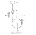
図3に示すように、直径90mmの金属製治具3にポリウレタン樹脂製チューブ(内径2.5mm、外径4.0mm長さ200mm)2を半周分にわたり接着固定しこの治具3を引張試験機の固定チャック7に取り付けた。
Hereinafter, the present invention will be described more specifically with reference to examples.
(1) Friction resistance measurement method As shown in FIG. 3, a polyurethane resin tube (inner diameter 2.5 mm, outer diameter 4.0 mm, length 200 mm) 2 is bonded to a
その後前記フッ素樹脂被覆ワイヤー1を前記ポリウレタン樹脂チューブに挿入しワイヤーの一方を引張試験機5のクリップ4に固定し、他方はフリーの状態で矢印6の方向に1分間に50mmの速度で引張り、このときの荷重を測定することによりワイヤー1とポリウレタン樹脂製チューブとの摩擦抵抗を測定した。引張り強さが小さいほど摩擦抵抗は小さいことになる。測定は、ガイドワイヤーの任意の点の50mm部分の摩擦抵抗値を引張試験機で測定し、その値をチャートに記録させそのデータより平均値を算出した。
(2)フッ素樹脂で被覆された突起部の高さの測定方法
日本のキーエンス社製、超深度形状測定顕微鏡"VK-8550"を用いて、下記の条件で測定した。
照射レーザ:半導体レーザ、波長685nm
出力:0.45mW
倍率:100倍
測定深さ:5μm
移動ピッチ:0.05μm
レーザスキャン:9Hz
レーザ照射角度:垂直(上方からストレートに照射し、反射光を受光部で受光する。)
測定方法は、図8に示すように、レーザ光a1をストレートに照射し、反射光a2を図示しない受光部で受光し、その焦点距離からこの部分の距離(深さ)を測定する。このように突起部14でも同様にレーザ光b1の照射により、反射光b2を受光し、その焦点距離より、この位置の距離を測定する。すなわち、試料の一定面積部において試料の凹凸状態をその焦点距離から順次測定し、a1照射部を平坦部として、突起部14の高さを算出する。測定は、1サンプル5箇所の測定値より平均値で算出した。
Thereafter, the fluororesin-coated wire 1 is inserted into the polyurethane resin tube, and one of the wires is fixed to the clip 4 of the
(2) Method for Measuring Height of Projection Part Covered with Fluorine Resin Measurement was performed under the following conditions using an ultra-deep shape measurement microscope “VK-8550” manufactured by Keyence Corporation of Japan.
Irradiation laser: Semiconductor laser, wavelength 685 nm
Output: 0.45mW
Magnification: 100 times Measurement depth: 5 μm
Moving pitch: 0.05μm
Laser scan: 9Hz
Laser irradiation angle: vertical (irradiates straight from above, and the reflected light is received by the light receiving unit)
As shown in FIG. 8, the laser beam a1 is irradiated straight, the reflected light a2 is received by a light receiving unit (not shown), and the distance (depth) of this part is measured from the focal length. Thus, the
(実施例1)
長さ2m、直径0.35mmのTi-Ni(Ni:49-51 atomic%)超弾性合金ワイヤーに、粘度110cp(23℃)に調整したプライマー溶液(固形分濃度35%の"855-300"(デュポン社製商品名))を乾燥後の厚さで約1μmの厚さにコーティングし、10分間常温で自然乾燥した。その後、150℃で30分間加熱した。
Example 1
Primer solution ("855-300" with a solid content concentration of 35%) adjusted to a viscosity of 110 cp (23 ° C) on a Ti-Ni (Ni: 49-51 atomic%) superelastic alloy wire with a length of 2 m and a diameter of 0.35 mm (Trade name, manufactured by DuPont) was coated to a thickness of about 1 μm after drying, and naturally dried at room temperature for 10 minutes. Then, it heated at 150 degreeC for 30 minutes.
別に、最外層のフッ素樹脂として、"855-510"(デュポン社製商品名)の被膜用フッ素樹脂ディスパージョンを用いた。フッ素樹脂固形分濃度は50重量%であった。このディスパージョンに突起形成用PTFE粒子(旭硝子社製商品名“L150J”)(平均粒子径約9μm)を前記ディスパージョンのフッ素樹脂重量に対して20重量%添加して混合し、これをコーティング液とした。 Separately, a fluororesin dispersion for coating of “855-510” (trade name, manufactured by DuPont) was used as the outermost fluororesin. The fluororesin solid content concentration was 50% by weight. Protrusion-forming PTFE particles (trade name “L150J” manufactured by Asahi Glass Co., Ltd.) (average particle diameter of about 9 μm) were added to and mixed with this dispersion in an amount of 20 wt% with respect to the fluororesin weight of the dispersion. It was.
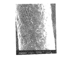
このコーティング液を、前記プライマー溶液をコートしたワイヤーにコーティングし、1分間常温(25℃)で自然乾燥し、200℃で10分間加熱し、その後450℃で1分間焼成し、室温まで冷却した。フッ素樹脂被膜層の平滑な部分の厚さは約5μm、突起部の平均高さは約3.5μmであった。 This coating solution was coated on the wire coated with the primer solution, naturally dried at room temperature (25 ° C.) for 1 minute, heated at 200 ° C. for 10 minutes, then baked at 450 ° C. for 1 minute, and cooled to room temperature. The thickness of the smooth portion of the fluororesin coating layer was about 5 μm, and the average height of the protrusions was about 3.5 μm.
このようにして得られたフッ素樹脂被覆ワイヤーの外観を図1に示す。図1は走査型電子顕微鏡(SEM)により倍率220倍で観察した写真である。図1から明らかなとおり、フッ素樹脂被膜層とそのフッ素樹脂被膜層表面に少なくとも平均1個/0.01mm2
以上の割合で凸状物が成形され、フッ素樹脂粒子とフッ素樹脂が一体化焼成され、凸状フッ素樹脂粒子は滑らかな突起を形成していることがわかる。
The appearance of the fluororesin-coated wire thus obtained is shown in FIG. FIG. 1 is a photograph observed at a magnification of 220 times with a scanning electron microscope (SEM). As is apparent from FIG. 1, the fluororesin coating layer and the fluororesin coating layer surface have an average of at least 1 piece / 0.01 mm @
Is convex particle is formed at a rate of above, fluorine resin particles and fluorine resin are integrated firing, convex fluororesin particles seen to form a smooth projection.
図2は、図1の模式的断面図である。フッ素樹脂被覆ワイヤー1は、超弾性合金ワイヤー11の表面に、プライマー層12とフッ素樹脂被膜層13とフッ素樹脂粒子による突起14が一体化焼成されていた。
FIG. 2 is a schematic cross-sectional view of FIG. In the fluororesin-coated wire 1, the
得られたフッ素樹脂被覆ワイヤーの摩擦抵抗値を測定した。この結果、実施例1のワイヤーの平均摩擦抵抗値は2.0gであった。 The friction resistance value of the obtained fluororesin-coated wire was measured. As a result, the average frictional resistance value of the wire of Example 1 was 2.0 g.
(実施例2)
実施例1において被膜用フッ素樹脂ディスパージョンにPTFEよりも融点が低いPFA微粒子分散ディスパージョンを用い、フッ素樹脂被膜形成時の焼成温度を変更した以外は実施例1と同様に実験を行った。PFA微粒子分散ディスパージョンに突起形成用PTFE粒子(平均粒子径約9μm)をフッ素樹脂重量に対して20重量%添加して混合し、長さ2m、直径0.35mmの超弾性合金ワイヤーにコーティングした。コーティング終了後、1分間常温で自然乾燥し、200℃で10分間加熱し、その後380℃で1分間焼成し、室温まで冷却した。フッ素樹脂被膜の平らな部分の厚さは約5μm、突起部の平均高さは約4μmであった。また、実施例2のワイヤーの平均摩擦抵抗値は1.8gであった。
(Example 2)
An experiment was conducted in the same manner as in Example 1 except that a PFA fine particle dispersion dispersion having a melting point lower than that of PTFE was used for the fluororesin dispersion for coating, and the firing temperature at the time of forming the fluororesin coating was changed. PTFE particles for protrusion formation (average particle diameter of about 9 μm) were added to and mixed with PFA fine particle-dispersed dispersion, and coated on a superelastic alloy wire having a length of 2 m and a diameter of 0.35 mm. . After coating, it was naturally dried at room temperature for 1 minute, heated at 200 ° C. for 10 minutes, then baked at 380 ° C. for 1 minute, and cooled to room temperature. The thickness of the flat part of the fluororesin coating was about 5 μm, and the average height of the protrusions was about 4 μm. Moreover, the average frictional resistance value of the wire of Example 2 was 1.8 g.
(比較例1)
実施例1において、突起形成用PTFE粒子をフッ素樹脂ディスパージョンに添加しなかった以外は、実施例1と同様にフッ素樹脂被膜を形成した。
(Comparative Example 1)
In Example 1, a fluororesin film was formed in the same manner as in Example 1 except that the protrusion-forming PTFE particles were not added to the fluororesin dispersion.
フッ素樹脂被覆ワイヤーの外観を図4に示す。図4は走査型電子顕微鏡(SEM)により倍率220倍で観察した写真である。図4から明らかなとおり、均一な厚さのフッ素樹脂被膜層が形成されていた。 The appearance of the fluororesin-coated wire is shown in FIG. FIG. 4 is a photograph observed with a scanning electron microscope (SEM) at a magnification of 220 times. As is clear from FIG. 4, a fluororesin coating layer having a uniform thickness was formed.
このフッ素樹脂被覆ワイヤーの摩擦抵抗値を実施例1と同様に測定したところ、ワイヤーの平均摩擦抵抗値は4.5gであった。 When the frictional resistance value of this fluororesin-coated wire was measured in the same manner as in Example 1, the average frictional resistance value of the wire was 4.5 g.
(比較例2)
平均粒子径9μmのPTFE粒子をワイヤー表面に粉体塗装し450℃の温度で1分間フッ素樹脂を焼成した。
(Comparative Example 2)
PTFE particles having an average particle diameter of 9 μm were powder-coated on the wire surface, and the fluororesin was baked at a temperature of 450 ° C. for 1 minute.
フッ素樹脂被覆ワイヤーの外観を図5に示す。図5は走査型電子顕微鏡(SEM)により倍率220倍で観察した写真である。図5から明らかなとおり、フッ素樹脂被膜層は凸凹状であった。 The appearance of the fluororesin-coated wire is shown in FIG. FIG. 5 is a photograph observed with a scanning electron microscope (SEM) at a magnification of 220 times. As is apparent from FIG. 5, the fluororesin coating layer was uneven.
このフッ素樹脂被覆ワイヤーの摩擦抵抗を実施例1と同様に測定したところ、ワイヤーの平均摩擦抵抗値は3.8gであった。 When the frictional resistance of this fluororesin-coated wire was measured in the same manner as in Example 1, the average frictional resistance value of the wire was 3.8 g.
(実施例3)
長さ2m、直径0.35mmのTi-Ni(Ni:49-51 atomic%)超弾性合金ワイヤーを用意した。次いでプライマー溶液として固形分濃度35%の"855-300"(デュポン社製商品名)に平均粒子径3μmのホウ酸アルミニウム"PF03"(四国化成工業社製商品名)を10wt%混合分散させ、粘度110cp(23℃)に調整した。前記プライマーを乾燥後の厚さが約1.0μmの厚さになるよう浸漬方法でコーティングし、10分間常温で自然乾燥しその後、150℃で30分間加熱した。乾燥後のプライマー被膜面は多数の凸形状のホウ酸アルミニウムがワイヤー表面に析出したような形でプライマー被膜とともにコーティングされていた。
(Example 3)
A Ti—Ni (Ni: 49-51 atomic%) superelastic alloy wire having a length of 2 m and a diameter of 0.35 mm was prepared. Next, 10 wt% of aluminum borate “PF03” (trade name, manufactured by Shikoku Kasei Kogyo Co., Ltd.) having an average particle diameter of 3 μm is mixed and dispersed in “855-300” (trade name, manufactured by DuPont) having a solid content concentration of 35% as a primer solution. The viscosity was adjusted to 110 cp (23 ° C.). The primer was coated by a dipping method so that the thickness after drying was about 1.0 μm, naturally dried at room temperature for 10 minutes, and then heated at 150 ° C. for 30 minutes. The surface of the primer coating after drying was coated with the primer coating in such a manner that a number of convex aluminum borates were deposited on the wire surface.
次に最外層のフッ素樹脂層としてPTFEからなるフッ素樹脂微粒子の平均直径が光散乱法の測定で約0.20μmである被膜用フッ素樹脂ディスパージョン(旭硝子社製商品名"AD−1")を用いた。フッ素樹脂固形分濃度は60wt%であり(トライトン)ポリオキシエチレン(10)オクチルフェニルエーテルを用い150CPの粘度に調整しこのディスパージョンを最外フッ素樹脂層のコーティング液とした。 Next, a fluororesin dispersion for coating (trade name “AD-1” manufactured by Asahi Glass Co., Ltd.) whose average diameter of fluororesin particles made of PTFE is about 0.20 μm as measured by a light scattering method as the outermost fluororesin layer. Using. The fluororesin solid content concentration was 60 wt% (Triton) polyoxyethylene (10) octylphenyl ether, and the viscosity was adjusted to 150 CP. This dispersion was used as the coating liquid for the outermost fluororesin layer.
このコーティング液を、前記プライマーをコートしたワイヤー表面にディッピングによりコーティングし、1分間常温で自然乾燥し、200℃で10分間加熱し、その後400℃で1分間焼成し、室温まで冷却した。フッ素樹脂被膜層の平滑な部分の厚さは約6μmであり突起部の平均高さは約2.0μmであった。 This coating liquid was coated on the surface of the wire coated with the primer by dipping, naturally dried at room temperature for 1 minute, heated at 200 ° C. for 10 minutes, then baked at 400 ° C. for 1 minute, and cooled to room temperature. The thickness of the smooth portion of the fluororesin coating layer was about 6 μm, and the average height of the protrusions was about 2.0 μm.
このようにして得られたフッ素樹脂被覆ワイヤーの外観を図6に示す。図6は走査型電子顕微鏡(SEM)により倍率220倍で観察した写真である。図6から明らかなとおり、フッ素樹脂被膜層表面にプライマー溶液に混合したホウ酸アルミニウム粒子の凸状の形状がフッ素樹脂に被覆された状態で滑らかな凸形状に成形されて被覆層を有するガイドワイヤーを得た。 The appearance of the fluororesin-coated wire thus obtained is shown in FIG. FIG. 6 is a photograph observed at a magnification of 220 times with a scanning electron microscope (SEM). As is clear from FIG. 6, the guide wire having a coating layer formed on the surface of the fluororesin coating layer in a state where the convex shape of the aluminum borate particles mixed with the primer solution is covered with the fluororesin and having a smooth projection shape. Got.
図7は、本実施例のガイドワイヤーの模式的断面図である。フッ素樹脂被覆ワイヤー20は、超弾性合金ワイヤー21の表面に、ホウ酸アルミニウム粒子25を混合したプライマー層22とフッ素樹脂被膜層23が積層され、ホウ酸アルミニウム粒子25がフッ素樹脂層で被覆された突起24が滑らかな凸状に被覆されていた。
FIG. 7 is a schematic cross-sectional view of the guide wire of the present embodiment. In the fluororesin-coated
得られたフッ素樹脂被覆ワイヤーの平均摩擦抵抗値は1.5gであった。 The average frictional resistance value of the obtained fluororesin-coated wire was 1.5 g.
(実施例4)
実施例3のプライマー溶液に、ホウ酸アルミニウムに換え、PTFE粒子(旭硝子社製商品名“L150J”)(平均粒子径約9μm)を前記プライマー溶液の固形分濃度に対し20重量%添加して混合し、これをプライマー溶液とし浸漬方法によって長さ2m、直径0.35mmの超弾性合金ワイヤーに2μmの厚みにコーティングした。その後10分間常温で自然乾燥し、150℃で30分間加熱乾燥した。乾燥後のプライマー被膜面は多数の凸形状のフッ素樹脂がワイヤー表面に析出したような形でプライマー被膜とともにコーティングされていた。その後PTFEよりも融点が低いPFA微粒子分散ディスパージョンを用い浸漬方法によりコーティング後、1分間常温で自然乾燥し、200℃で10分間加熱し、その後380℃で1分間焼成し、室温まで冷却した。フッ素樹脂被膜の平らな部分の厚さは約7μm、突起部の高さ約5μmであった。また、平均摩擦抵抗値は1.8gであった。
Example 4
To the primer solution of Example 3, instead of aluminum borate, PTFE particles (trade name “L150J” manufactured by Asahi Glass Co., Ltd.) (average particle diameter of about 9 μm) were added at 20 wt% with respect to the solid content concentration of the primer solution and mixed. Then, this was used as a primer solution and coated on a superelastic alloy wire having a length of 2 m and a diameter of 0.35 mm by a dipping method to a thickness of 2 μm. Thereafter, it was naturally dried at room temperature for 10 minutes and then heat-dried at 150 ° C. for 30 minutes. The surface of the primer film after drying was coated with the primer film in such a manner that a number of convex fluororesins were deposited on the wire surface. Thereafter, coating was performed by a dipping method using a PFA fine particle dispersion having a melting point lower than that of PTFE, and then naturally dried at room temperature for 1 minute, heated at 200 ° C. for 10 minutes, then baked at 380 ° C. for 1 minute, and cooled to room temperature. The flat part of the fluororesin film had a thickness of about 7 μm, and the height of the protrusions was about 5 μm. The average frictional resistance value was 1.8 g.
以上の実施例及び比較例から明らかなとおり、本発明のフッ素樹脂被膜層と突起形成用フッ素樹脂粒子とが一体化焼成され、凸状フッ素樹脂粒子が滑らかな突起を形成しているワイヤーは、摩擦抵抗値がもっとも低かった。 As is clear from the above Examples and Comparative Examples, wire with the fluorine resin coating layer of the present invention a protrusion for forming the fluororesin particles are integrated firing, convex fluororesin particles form a smooth projection, The frictional resistance value was the lowest.
1,20 フッ素樹脂被覆ワイヤー
2 樹脂製チューブ
3 金属製治具
4 クリップ
5 引張試験機
7 固定チャック
11,21 超弾性合金ワイヤー
12,22 プライマー層
13,23 フッ素樹脂被膜層
14,24 突起
25 ホウ酸アルミニウム粒子
DESCRIPTION OF
Claims (18)
前記金属製ワイヤーはストレート状又は先端先細のテーパー状であり、
前記フッ素樹脂被膜層に粒子状物質が存在し、前記フッ素樹脂被膜層形成時に前記フッ素樹脂被膜層を構成するフッ素樹脂の融点以上で焼成することにより、
前記フッ素樹脂被膜層は粒子状物質を覆い、かつ前記粒子状物質の少なくとも一部は表面凸形状の突起に形成されている医療用ガイドワイヤー。 A medical guide wire in which at least a fluororesin coating layer is formed on the surface of a metal wire,
The metal wire is straight or tapered at the tip,
Particulate matter is present in the fluororesin coating layer, and when the fluororesin coating layer is formed, by firing at a melting point or higher of the fluororesin constituting the fluororesin coating layer,
The fluororesin coating layer covers a particulate material, and at least a part of the particulate material is a medical guide wire formed on a protrusion having a convex surface.
前記プライマー層及びフッ素樹脂被膜層から選ばれる少なくとも一つの層に粒子状物質が存在し、
最外層の前記フッ素樹脂被膜層は前記粒子状物質を覆い、かつ前記粒子状物質の少なくとも一部は表面凸形状の突起に形成されている請求項1に記載の医療用ガイドワイヤー。 A primer layer is further formed on the inner layer of the fluororesin coating layer,
Particulate matter is present in at least one layer selected from the primer layer and the fluororesin coating layer,
The medical guide wire according to claim 1, wherein the outermost fluororesin coating layer covers the particulate matter, and at least a part of the particulate matter is formed as a convex protrusion on the surface.
前記金属製ワイヤーはストレート状又は先端先細のテーパー状であり、
フッ素樹脂ディスパージョン中に突起用粒子状物質を混合してコーティング溶液を調製し、
前記溶液を前記金属製ワイヤーの表面に塗布し、乾燥後、前記フッ素樹脂ディスパージョンのフッ素樹脂の融点以上に加熱焼成することにより、
前記フッ素樹脂被膜層に前記粒子状物質を存在させ、
前記フッ素樹脂被膜層は前記粒子状物質を覆い、かつ前記粒子状物質の少なくとも一部を表面凸形状の突起に形成することを特徴とする医療用ガイドワイヤーの製造方法。 A method for producing a medical guide wire in which at least a fluororesin coating layer is formed on the surface of a metal wire,
The metal wire is straight or tapered at the tip,
Prepare the coating solution by mixing the particulate material for protrusions in the fluororesin dispersion,
The solution is applied to the surface of the metal wire, dried, and heated and fired above the melting point of the fluororesin of the fluororesin dispersion.
The particulate matter is present in the fluororesin coating layer;
Production method of the fluorine resin coating layer is not covering the particulate matter, and a medical guidewire, wherein that you forming at least a portion the projection of the surface convex shape of the particulate material.
前記金属製ワイヤーはストレート状又は先端先細のテーパー状であり、
プライマー溶液及びフッ素樹脂ディスパージョン溶液から選ばれる少なくとも一つの溶液中に粒子状物質を混合し、
前記プライマー溶液とフッ素樹脂ディスパージョン溶液を前記金属製ワイヤーの表面にこの順番に塗布し、乾燥し、
最終工程で前記フッ素樹脂ディスパージョンのフッ素樹脂の融点以上に加熱焼成することにより、最外層の前記フッ素樹脂被膜層が前記粒子状物質を覆い、かつ前記粒子状物質の少なくとも一部を表面凸形状の突起に形成することを特徴とする医療用ガイドワイヤーの製造方法。 A method for producing a medical guide wire in which a primer layer and a fluororesin coating layer are formed in this order on the surface of a metal wire,
The metal wire is straight or tapered at the tip,
Mix particulate matter in at least one solution selected from a primer solution and a fluororesin dispersion solution,
The primer solution and the fluororesin dispersion solution are applied to the surface of the metal wire in this order and dried.
By firing than the fluorine resin dispersion of the fluororesin melting point in the final step, the fluorine resin coating layer of the outermost layer is not covered with the particulate material, and at least part of the surface projection of the particulate material method for producing a medical guide wire which is characterized that you formed in the shape of a protrusion.
Priority Applications (1)
| Application Number | Priority Date | Filing Date | Title |
|---|---|---|---|
| JP2003323590A JP3876243B2 (en) | 2002-09-20 | 2003-09-16 | Medical guide wire and manufacturing method thereof |
Applications Claiming Priority (2)
| Application Number | Priority Date | Filing Date | Title |
|---|---|---|---|
| JP2002276139 | 2002-09-20 | ||
| JP2003323590A JP3876243B2 (en) | 2002-09-20 | 2003-09-16 | Medical guide wire and manufacturing method thereof |
Publications (3)
| Publication Number | Publication Date |
|---|---|
| JP2004130123A JP2004130123A (en) | 2004-04-30 |
| JP2004130123A5 JP2004130123A5 (en) | 2006-09-07 |
| JP3876243B2 true JP3876243B2 (en) | 2007-01-31 |
Family
ID=32301796
Family Applications (1)
| Application Number | Title | Priority Date | Filing Date |
|---|---|---|---|
| JP2003323590A Expired - Lifetime JP3876243B2 (en) | 2002-09-20 | 2003-09-16 | Medical guide wire and manufacturing method thereof |
Country Status (1)
| Country | Link |
|---|---|
| JP (1) | JP3876243B2 (en) |
Families Citing this family (12)
| Publication number | Priority date | Publication date | Assignee | Title |
|---|---|---|---|---|
| JP2006068497A (en) * | 2004-08-03 | 2006-03-16 | Ist:Kk | Method for manufacturing medical wire and medical wire |
| JP2006320638A (en) * | 2005-05-20 | 2006-11-30 | Ist Corp | Method for manufacturing medical wire |
| AU2006292664A1 (en) * | 2005-09-15 | 2007-03-29 | Wilson-Cook Medical Inc. | Multiple stage wire guide |
| JP2008086575A (en) | 2006-10-02 | 2008-04-17 | Ist Corp | Manufacturing method for colored medical tool |
| JP5249591B2 (en) * | 2007-03-23 | 2013-07-31 | テルモ株式会社 | Guide wire |
| US9028427B2 (en) | 2007-03-14 | 2015-05-12 | Terumo Kabushiki Kaisha | Guide wire |
| JP2016168063A (en) * | 2013-07-29 | 2016-09-23 | テルモ株式会社 | Guide wire |
| JP2018103109A (en) * | 2016-12-27 | 2018-07-05 | 東洋紡株式会社 | Electret filter and method for manufacturing electret filter |
| JP2018103108A (en) * | 2016-12-27 | 2018-07-05 | 東洋紡株式会社 | Electret filter |
| JP2018188621A (en) * | 2017-04-28 | 2018-11-29 | アクロス株式会社 | Coat for slide members and slide member having the same |
| CN116322860A (en) * | 2020-10-02 | 2023-06-23 | 朝日英达科株式会社 | Long medical appliance |
| JPWO2022130632A1 (en) * | 2020-12-18 | 2022-06-23 |
-
2003
- 2003-09-16 JP JP2003323590A patent/JP3876243B2/en not_active Expired - Lifetime
Also Published As
| Publication number | Publication date |
|---|---|
| JP2004130123A (en) | 2004-04-30 |
Similar Documents
| Publication | Publication Date | Title |
|---|---|---|
| KR101062613B1 (en) | Medical guide wire and its manufacturing method | |
| JP3876243B2 (en) | Medical guide wire and manufacturing method thereof | |
| JP5412013B2 (en) | Medical catheter tube and manufacturing method thereof | |
| AU2012255972B2 (en) | Implantable materials having engineered surfaces and method of making same | |
| JP2002505167A (en) | Flexible and kink-resistant low friction guidewire having a formable tip and method of manufacturing the same | |
| JP2009515604A (en) | Lubricating compounds and medical devices made therefrom | |
| JP6251903B2 (en) | Medical guidewire | |
| JPWO2006077951A1 (en) | Catheter and method for manufacturing the same | |
| Drevet et al. | Thermal treatment optimization of electrodeposited hydroxyapatite coatings on Ti6Al4V substrate | |
| JP2019177222A (en) | Biofilm resistant medical implant | |
| JP5763086B2 (en) | Surgical needle coating and method | |
| JP2015100664A (en) | Fluorine coated wire | |
| JP2019130880A (en) | Polytetrafluoroethylene tube | |
| Feig et al. | Actively triggerable metals via liquid metal embrittlement for biomedical applications | |
| Olsson et al. | Production of osseointegrating (bone bonding) surfaces on titanium screws by laser melt disruption | |
| JP2006068497A (en) | Method for manufacturing medical wire and medical wire | |
| US20070096357A1 (en) | Medical tube and method for manufacturing the same | |
| WO2018174108A1 (en) | Resin moulded body, and method for producing resin moulded body | |
| JP2020533129A (en) | Coated surgical suture needle | |
| JP2008086575A (en) | Manufacturing method for colored medical tool | |
| US20190201065A1 (en) | Method for fabricating medical device and applications thereof | |
| TW201929980A (en) | Method for fabricating medical device and applications thereof | |
| Gradinaru et al. | Preliminary Results on Pulsed Laser Deposition of PMMA on Nitinol Substrate | |
| US20220296861A1 (en) | Guide wire | |
| JP5082058B2 (en) | Medical instruments |
Legal Events
| Date | Code | Title | Description |
|---|---|---|---|
| A521 | Request for written amendment filed |
Free format text: JAPANESE INTERMEDIATE CODE: A523 Effective date: 20050920 |
|
| A621 | Written request for application examination |
Free format text: JAPANESE INTERMEDIATE CODE: A621 Effective date: 20050920 |
|
| A521 | Request for written amendment filed |
Free format text: JAPANESE INTERMEDIATE CODE: A523 Effective date: 20050926 |
|
| A521 | Request for written amendment filed |
Free format text: JAPANESE INTERMEDIATE CODE: A523 Effective date: 20060721 |
|
| A871 | Explanation of circumstances concerning accelerated examination |
Free format text: JAPANESE INTERMEDIATE CODE: A871 Effective date: 20060721 |
|
| A975 | Report on accelerated examination |
Free format text: JAPANESE INTERMEDIATE CODE: A971005 Effective date: 20060810 |
|
| A131 | Notification of reasons for refusal |
Free format text: JAPANESE INTERMEDIATE CODE: A131 Effective date: 20060824 |
|
| A521 | Request for written amendment filed |
Free format text: JAPANESE INTERMEDIATE CODE: A523 Effective date: 20061002 |
|
| TRDD | Decision of grant or rejection written | ||
| A01 | Written decision to grant a patent or to grant a registration (utility model) |
Free format text: JAPANESE INTERMEDIATE CODE: A01 Effective date: 20061024 |
|
| A61 | First payment of annual fees (during grant procedure) |
Free format text: JAPANESE INTERMEDIATE CODE: A61 Effective date: 20061030 |
|
| R150 | Certificate of patent or registration of utility model |
Ref document number: 3876243 Country of ref document: JP Free format text: JAPANESE INTERMEDIATE CODE: R150 Free format text: JAPANESE INTERMEDIATE CODE: R150 |
|
| FPAY | Renewal fee payment (event date is renewal date of database) |
Free format text: PAYMENT UNTIL: 20101102 Year of fee payment: 4 |
|
| R250 | Receipt of annual fees |
Free format text: JAPANESE INTERMEDIATE CODE: R250 |
|
| FPAY | Renewal fee payment (event date is renewal date of database) |
Free format text: PAYMENT UNTIL: 20101102 Year of fee payment: 4 |
|
| FPAY | Renewal fee payment (event date is renewal date of database) |
Free format text: PAYMENT UNTIL: 20111102 Year of fee payment: 5 |
|
| R250 | Receipt of annual fees |
Free format text: JAPANESE INTERMEDIATE CODE: R250 |
|
| FPAY | Renewal fee payment (event date is renewal date of database) |
Free format text: PAYMENT UNTIL: 20111102 Year of fee payment: 5 |
|
| FPAY | Renewal fee payment (event date is renewal date of database) |
Free format text: PAYMENT UNTIL: 20121102 Year of fee payment: 6 |
|
| R250 | Receipt of annual fees |
Free format text: JAPANESE INTERMEDIATE CODE: R250 |
|
| S111 | Request for change of ownership or part of ownership |
Free format text: JAPANESE INTERMEDIATE CODE: R313113 |
|
| FPAY | Renewal fee payment (event date is renewal date of database) |
Free format text: PAYMENT UNTIL: 20121102 Year of fee payment: 6 |
|
| R350 | Written notification of registration of transfer |
Free format text: JAPANESE INTERMEDIATE CODE: R350 |
|
| FPAY | Renewal fee payment (event date is renewal date of database) |
Free format text: PAYMENT UNTIL: 20121102 Year of fee payment: 6 |
|
| FPAY | Renewal fee payment (event date is renewal date of database) |
Free format text: PAYMENT UNTIL: 20131102 Year of fee payment: 7 |
|
| R250 | Receipt of annual fees |
Free format text: JAPANESE INTERMEDIATE CODE: R250 |
|
| R250 | Receipt of annual fees |
Free format text: JAPANESE INTERMEDIATE CODE: R250 |
|
| R250 | Receipt of annual fees |
Free format text: JAPANESE INTERMEDIATE CODE: R250 |
|
| S111 | Request for change of ownership or part of ownership |
Free format text: JAPANESE INTERMEDIATE CODE: R313113 |
|
| R360 | Written notification for declining of transfer of rights |
Free format text: JAPANESE INTERMEDIATE CODE: R360 |
|
| R350 | Written notification of registration of transfer |
Free format text: JAPANESE INTERMEDIATE CODE: R350 |
|
| S303 | Written request for registration of pledge or change of pledge |
Free format text: JAPANESE INTERMEDIATE CODE: R316303 |
|
| R350 | Written notification of registration of transfer |
Free format text: JAPANESE INTERMEDIATE CODE: R350 |
|
| RD03 | Notification of appointment of power of attorney |
Free format text: JAPANESE INTERMEDIATE CODE: R3D03 |
|
| R250 | Receipt of annual fees |
Free format text: JAPANESE INTERMEDIATE CODE: R250 |
|
| S803 | Written request for registration of cancellation of provisional registration |
Free format text: JAPANESE INTERMEDIATE CODE: R316803 |
|
| R350 | Written notification of registration of transfer |
Free format text: JAPANESE INTERMEDIATE CODE: R350 |
|
| S111 | Request for change of ownership or part of ownership |
Free format text: JAPANESE INTERMEDIATE CODE: R313113 |
|
| R350 | Written notification of registration of transfer |
Free format text: JAPANESE INTERMEDIATE CODE: R350 |
|
| R250 | Receipt of annual fees |
Free format text: JAPANESE INTERMEDIATE CODE: R250 |
|
| R250 | Receipt of annual fees |
Free format text: JAPANESE INTERMEDIATE CODE: R250 |
|
| R250 | Receipt of annual fees |
Free format text: JAPANESE INTERMEDIATE CODE: R250 |
|
| R250 | Receipt of annual fees |
Free format text: JAPANESE INTERMEDIATE CODE: R250 |
|
| R250 | Receipt of annual fees |
Free format text: JAPANESE INTERMEDIATE CODE: R250 |
|
| R250 | Receipt of annual fees |
Free format text: JAPANESE INTERMEDIATE CODE: R250 |
|
| R250 | Receipt of annual fees |
Free format text: JAPANESE INTERMEDIATE CODE: R250 |
|
| EXPY | Cancellation because of completion of term |