JP3874392B2 - Chair - Google Patents
Chair Download PDFInfo
- Publication number
- JP3874392B2 JP3874392B2 JP09881299A JP9881299A JP3874392B2 JP 3874392 B2 JP3874392 B2 JP 3874392B2 JP 09881299 A JP09881299 A JP 09881299A JP 9881299 A JP9881299 A JP 9881299A JP 3874392 B2 JP3874392 B2 JP 3874392B2
- Authority
- JP
- Japan
- Prior art keywords
- shell
- backrest
- bent
- upper shell
- frame
- Prior art date
- Legal status (The legal status is an assumption and is not a legal conclusion. Google has not performed a legal analysis and makes no representation as to the accuracy of the status listed.)
- Expired - Fee Related
Links
Images


Classifications
-
- A—HUMAN NECESSITIES
- A47—FURNITURE; DOMESTIC ARTICLES OR APPLIANCES; COFFEE MILLS; SPICE MILLS; SUCTION CLEANERS IN GENERAL
- A47C—CHAIRS; SOFAS; BEDS
- A47C7/00—Parts, details, or accessories of chairs or stools
- A47C7/36—Support for the head or the back
- A47C7/40—Support for the head or the back for the back
- A47C7/405—Support for the head or the back for the back with double backrests
-
- A—HUMAN NECESSITIES
- A47—FURNITURE; DOMESTIC ARTICLES OR APPLIANCES; COFFEE MILLS; SPICE MILLS; SUCTION CLEANERS IN GENERAL
- A47C—CHAIRS; SOFAS; BEDS
- A47C1/00—Chairs adapted for special purposes
- A47C1/02—Reclining or easy chairs
- A47C1/031—Reclining or easy chairs having coupled concurrently adjustable supporting parts
- A47C1/032—Reclining or easy chairs having coupled concurrently adjustable supporting parts the parts being movably-coupled seat and back-rest
- A47C1/03261—Reclining or easy chairs having coupled concurrently adjustable supporting parts the parts being movably-coupled seat and back-rest characterised by elastic means
- A47C1/03283—Reclining or easy chairs having coupled concurrently adjustable supporting parts the parts being movably-coupled seat and back-rest characterised by elastic means with fluid springs
-
- A—HUMAN NECESSITIES
- A47—FURNITURE; DOMESTIC ARTICLES OR APPLIANCES; COFFEE MILLS; SPICE MILLS; SUCTION CLEANERS IN GENERAL
- A47C—CHAIRS; SOFAS; BEDS
- A47C7/00—Parts, details, or accessories of chairs or stools
- A47C7/36—Support for the head or the back
- A47C7/40—Support for the head or the back for the back
- A47C7/44—Support for the head or the back for the back with elastically-mounted back-rest or backrest-seat unit in the base frame
- A47C7/445—Support for the head or the back for the back with elastically-mounted back-rest or backrest-seat unit in the base frame with bar or leaf springs
-
- A—HUMAN NECESSITIES
- A47—FURNITURE; DOMESTIC ARTICLES OR APPLIANCES; COFFEE MILLS; SPICE MILLS; SUCTION CLEANERS IN GENERAL
- A47C—CHAIRS; SOFAS; BEDS
- A47C7/00—Parts, details, or accessories of chairs or stools
- A47C7/36—Support for the head or the back
- A47C7/40—Support for the head or the back for the back
- A47C7/46—Support for the head or the back for the back with special, e.g. adjustable, lumbar region support profile; "Ackerblom" profile chairs
-
- Y—GENERAL TAGGING OF NEW TECHNOLOGICAL DEVELOPMENTS; GENERAL TAGGING OF CROSS-SECTIONAL TECHNOLOGIES SPANNING OVER SEVERAL SECTIONS OF THE IPC; TECHNICAL SUBJECTS COVERED BY FORMER USPC CROSS-REFERENCE ART COLLECTIONS [XRACs] AND DIGESTS
- Y10—TECHNICAL SUBJECTS COVERED BY FORMER USPC
- Y10S—TECHNICAL SUBJECTS COVERED BY FORMER USPC CROSS-REFERENCE ART COLLECTIONS [XRACs] AND DIGESTS
- Y10S297/00—Chairs and seats
- Y10S297/02—Molded
Landscapes
- Health & Medical Sciences (AREA)
- Dentistry (AREA)
- General Health & Medical Sciences (AREA)
- Chair Legs, Seat Parts, And Backrests (AREA)
- Chairs Characterized By Structure (AREA)
- Chairs For Special Purposes, Such As Reclining Chairs (AREA)
- Special Chairs (AREA)
Description
【0001】
【発明の属する技術分野】
本発明は、パーソナルコンピュータ等のOA機器の操作に適するとともに、リクライニング時に安定した姿勢を確保できるようにした椅子に関する。
【0002】
【従来の技術】
パーソナルコンピュータ等のOA機器を使用したデスクワークにおける様々な姿勢や、作業姿勢の変化に対応して、適切に体を支持するために、座面や背もたれを、傾斜又はリクライニングさせる機構を搭載した椅子は公知である。
【0003】
このような椅子には、背もたれ部分が後方へ傾斜したときに、背もたれの上部を後傾角度と常時同じ角度に保つようにしたもの、或いは、背もたれ部分のリクライニング角度に拘わらず、背もたれの上部を常に同じ傾斜角度を保つようにしたパラレルリンク機構を内蔵したものがある。
【0004】
【発明が解決しようとする課題】
しかし、前述した従来の椅子のうち、前者では、後傾した時に、頭部の位置が後方に大きく移動し、パーソナルコンピュータのディスプレィ等が、見づらくなるという難点がある。即ち、背もたれにもたれ掛かった状態では、自然な視線の方向が水平よりも上方を向いてしまい、机上のモニタ画面を見る角度として、一般に適当であると言われている水平から5゜〜10゜下方を見るような姿勢を、従来の椅子で無理に採ろうとすると、頭部を前に起こさなければならず、肩こりや首の疲れの原因となる。
【0005】
また、無理に頭部を前方へ起こした場合には、背もたれの形状と、背中のカーブとが合わず、背もたれから身体が浮いてしまう部分が生じるため、姿勢が不安定な状態となり、その結果、安定した後傾姿勢を採ることができなくなり、疲労の原因となる。
【0006】
前述した従来の椅子のうち、後者では、背もたれのリクライニング角度に拘わらず、背もたれの上部を常に同じ傾斜角度に保つため、背もたれのリクライニング時に、着席者は、猫背姿勢を余儀なくされ、圧迫感を感じるようになる。
【0007】
本発明は、従来の技術が有する上述のような問題点に鑑みてなされたもので、さまざまに姿勢が変化する作業を行う場合に、常に適切な姿勢を保持することができるようにした椅子を提供することを目的としている。
また、パーソナルコンピュータ等のOA機器を使用する際に、視線をディスプレィに向けながらもリラックスした姿勢を採ることのできる椅子を提供することを目的としている。
【0008】
【課題を解決するための手段】
本発明は、次のようにして上記課題を解決している。
(1) 着座部の後部に、背もたれフレームを立設し、この背もたれフレームの前面に取り付けられる背もたれ板を、上部シェルと下部シェルとを有するものとし、前記上部シェルの上部と下部シェルの下部とを、それぞれ前記背もたれフレームの上部と下部とに取り付けるとともに、前記上部シェルの下部と下部シェルの上部とを、前後方向に弾性撓曲可能とした折れ曲がり部を介して互いに連結し、前記背もたれ板が後方に押圧されたときに、前記上部シェルは、前記下部シェルに対して前記折れ曲がり部において前方へ傾動し、前記背もたれ板の上部から下部にかけて連続する屈曲面を形成するようにする。
【0009】
(2) 上記(1)項において、上部シェルの上部と下部シェルの下部とのいずれか一方を、背もたれフレームの上部または下部に、ほぼ上下方向にスライド可能として取り付ける。
【0010】
(3) 上記(1)または(2)項において、上部シェルの上部と下部シェルの下部との少なくともいずれか一方を、背もたれフレームの上部または下部に、前後方向に傾動可能として取り付ける。
【0011】
(4) 上記(1)〜(3)項のいずれかにおいて、上部シェルと下部シェルとの間に、中間部シェルを設け、前記上部シェルと中間部シェルと下部シェルとの相互の間を、前後方向に弾性撓曲可能とした折れ曲がり部を介して互いに連結する。
【0012】
(5) 上記(1)〜(4)項のいずれかにおいて、折れ曲がり部を、側面視波形とする。
【0013】
(6) 上記(1)〜(5)項のいずれかにおいて、上部シェルの上部または下部シェルの下部に設けた枢軸を、背もたれフレームの上部または下部に設けたほぼ上下方向を向くスライド溝に嵌合し、かつ、このスライド溝を前方に凸となるように湾曲させる。
【0014】
(7) 上記(1)〜(6)項のいずれかにおいて、背もたれ板を、弾性を有する硬質合成樹脂材料等を成形して、少なくとも上部シェルと下部シェルと折れ曲がり部とが一体となるように形成する。
【0015】
(8) 上記(1)〜(7)項のいずれかにおいて、背もたれフレームを、着座部の下面に設けられた支基付近の支点を中心として傾動可能とする。
【0016】
(9) 上記(1)〜(8)項のいずれかにおいて、背もたれ板と背もたれフレームとの間に、前記背もたれ板の折れ曲がり部と等高位置で屈撓可能で、かつ前記背もたれフレーム及び前記背もたれ板の少なくとも一方に対してスライド可能な補強材を介在させる。
【0017】
(10) 上記(1)〜(9)項のいずれかにおいて、着席者の背中の荷重が掛からないときの背もたれ板の側面形状を、中間部が後方に凹入するように屈曲する形状とする。
【0018】
【発明の実施の形態】
次に、本発明に係る椅子の実施形態を、添付図面を参照しながら説明する。
【0019】
図1は、本発明の第1の実施形態の椅子の要部である背もたれ部分の構造を示した分解斜視図である。同図に示すように、本実施形態の椅子の背もたれ部分は、背もたれフレーム(10)と、左右1対の補強材(12)(12)と、背もたれ板(14)と、背クッション材(16)等とから構成されている。
【0020】
背もたれフレーム(10)は、左右1対のパイプ材からなり、その下端部である横杆部(10a)は、前方へ延出し、その先端は、図示しない座板に取り付けられ、後述する支基を支点として、後方へ傾動可能になっている。
【0021】
一方、縦杆部(10b)は、2箇所でくの字状に屈曲して形成されている。左右の縦杆部(10b)(10b)の上部間及び下部間は、平行な2本の水平杆(18)(18)によって連結されている。
【0022】
背もたれフレーム(10)の縦杆部(10b)の上部と下部との間には、左右に1対ずつ、弾性体の帯状の補強材(12)(12)が取り付けられている。このうち、縦杆部(10b)の上部には、角度可変となるように、1対のブラケット(20)(20)が各縦杆部(10b)を両側から挟み込むようにして枢支され、ブラケット(20)の前部には、鍔部を有するガイドピン(20a)が突設されている。ガイドピン(20a)には、補強材(12)の上部に穿設された上下方向に長いガイド孔(12b)が嵌合しており、補強材(12)の上端部を一定範囲で上下にスライド自在に案内している。
【0023】
補強材(12)は、弾性を有する材料、例えば樹脂等で形成されており、一定の張力をもって、背もたれフレーム(10)の上部及び下部間を連結している。補強材(12)のほぼ中央部には、後部側にくの字状に屈曲した屈曲部(12a)が形成されており、背もたれ板(14)の取付時に、後述する両側の折れ曲がり部(14c)(14c)が、それぞれ嵌合して、後述するように、背もたれ板(14)と等高位置で屈撓可能になっている。
【0024】
背もたれ板(14)は、上部シェル(14a)と下部シェル(14b)とを備え、折れ曲がり部(14c)を境に、その端部間が前後方向に屈撓可能に連結されている。下部シェル(14b)の下端は補強材(12)の下部に、上部シェル(14a)の上端は補強材(12)の上部にそれぞれ止めねじ(22)によって取り付けられ、これにより、補強材(12)は、背もたれ板(14)と、背もたれフレーム(10)との間に介在されることになる。
【0025】
上部シェル(14a)の両側上端には、縦長のスライド孔(24)が穿設され、このスライド孔(24)は、前述したガイドピン(20a)と嵌合して上下動可能に案内されている。これにより、背もたれ板(14)は、補強材(12)が上下動すると、一体となって上下方向に移動するようになっている。
【0026】
背もたれ板(14)は、通常、図1および図2に示すように、後述する背クッション材(16)の裏面のカーブと同一の、側面視において中間部が後方に凹入する円弧状の曲面とされているが、下部シェル(14b)に後ろ向きの力が加わると、折れ曲がり部(14c)を境に上部シェル(14a)が前方に傾動する弾性を有している。
【0027】
背もたれ板(14)の表面には、背クッション材(16)が所定の手段によって取り付けられ、椅子の背部を形成している。
【0028】
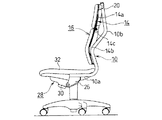
図2は、図1の椅子の背部を含む椅子全体を示す側面図である。図2に示すように、背もたれフレーム(10)の横杆部(10a)は、取付片(26)を介して、椅子の座板(28)に設けられた支基(30)に傾動可能に取り付けられている。座板(28)には、座クッション材(32)が取り付けられている。
【0029】
次に、本実施形態の椅子の作用について説明する。
【0030】
図3は、椅子の背もたれを後方に傾動させた状態を示している。背もたれ全体を後傾させると、背もたれ板(14)の下部シェル(14b)に力が加わり、支基(30)を支点として下部シェル(14b)が後傾する。下部シェル(14b)の後方への移動に伴って、図1で示したガイド孔(12b)をガイドピン(20a)が案内して、補強材(12)を下方へスライドさせ、さらに荷重がかかると、ガイド孔(12b)の内側上部にガイドピン(20a)が当接して、補強材(12)は、屈曲部(12a)で屈曲する。
【0031】
すると、背もたれ板(14)は、補強材(12)が、その屈曲部(12a)が屈曲するのに伴って折れ曲がり部(14c)を境に、上部シェル(14a)が下部シェル(14b)に対して前傾し、背クッション材(16)の上部を前方に押し出す。即ち、図4に示すように、着席者が、通常の直立した姿勢から、図5に示す姿勢に移行した場合には、背中の上部を背クッション材(16)によって前方へ押して支持する。
【0032】
このために、本実施形態の椅子によれば、着席者の後傾する度合いに応じて、上部シェル(14a)が前方に傾動する角度が変化し、着席者にとって最適な角度となるように背クッション材(16)の上部を前方に押し出して、着席者の背中の上部を支持する。これにより、例えば、パソコン等のOA機器を使用する場合に、頭部を前に起こしてモニタ画面を見ながら、腰部より下の部分は後傾させるリラックスした姿勢を容易に採ることができる。
【0033】
また、本実施形態の椅子において、図5に示すように、後傾姿勢を採った場合は、上部シェル(14a)が前方に傾動し、着席者の背中を押すように支持するので、着席者の視線は、ほぼ水平となる。このため、モニタ画面を見るのに適した水平から5゜〜10゜下方を見る姿勢を容易に採ることができる。
【0034】
さらに、後傾姿勢の度合いに応じて、上部シェル(14a)の前方へ折れ曲がる角度が変わるので、圧迫感のない自然な座り心地が得られるとともに、姿勢変化に背クッション材(16)が滑らかに追従するため、背中のカーブにフィットして圧迫感のない座り心地を実現できる。
【0035】
即ち、図6に示すように、背中を図5の曲げた状態から伸ばした状態にした場合には、上部シェル(14a)がなめらかに後方へ傾動して背中の動きに追従するため、着席者にとって最もリラックスした姿勢を容易に採ることができ、長時間、椅子に座った際の疲労が少なくなる。
【0036】
加えて、椅子の左右に補強材(12)を設けてあるので、左右方向への体重移動に対しての背もたれ板(14)の追従性がよくなり、作業時の姿勢変化に柔軟に対応できる。さらに、椅子の背部の上方に、機構部を集中させてあるので、従来のものに比較して、小型軽量化が可能となるとともに、デザイン的にも洗練されたものとなる。
【0037】
なお、本実施形態では、補強材(12)を、背もたれ板(14)と、背もたれフレーム(10)との間に介在させているが、補強材(12)を介在させることなく、背もたれ板(14)だけでも同様の機能を発揮させることができる。
【0038】
本実施形態では、補強材(12)及び背もたれ板(14)の双方を、背もたれフレーム(10)の上端にスライド可能に取り付けているが、これらのうち、一方をスライド可能に取り付けるようにしてもよい。
【0039】
図7〜図9は、本発明の第2の実施形態を示す。なお、上述の第1の実施形態におけるのと同一または対応する部材には同一の符号を付して図示してある。
【0040】
第2の実施形態の背もたれフレーム(10)は、左右1対の金属または硬質合成樹脂製の杆材からなり、その下部の横杆部(10a)は前方へ延出し、その先端は支基(30)に取り付けられた、いわゆる背座シンクロリクライニングメカニズムに装着され、支基(30)付近の支点を中心として、後方へ傾動可能になっている。
【0041】
左右1対の上部の縦杆部(10b)は、上下2箇所で互いに逆向きのくの字状に屈曲して形成されている。すなわち、下部では、前方に凸に、上部では、後方に凸に屈曲されている。
【0042】
この縦杆部(10b)の上端部の前面には、上下方向のスライド溝(34a)を有する取付部(34)が前方に突出するようにして固定されている。スライド溝(34a)は、前方に凸の円弧状をなしており、その外側及び少なくとも上部が開放されている。
また、縦杆部(10b)の下部の屈曲部の前面には、上部が開口した水平軸受(36)が前方に突出するようにして固定されている。
【0043】
背もたれ板(14)は、例えば弾性を有する硬質の合成樹脂材料の成型品であって、上部シェル(14a)と下部シェル(14b)とからなり、上部シェル(14a)と下部シェル(14b)との境目は、上述の縦杆部(10b)の後方に凸の上部の屈曲部と等高の位置とされている。この位置は、着座者の胸椎と腰椎との境目に当たる。
【0044】
上部シェル(14a)の下端部と下部シェル(14b)の上端部とは、側面視で波形に形成されることにより、前後方向に弾性撓曲可能とした左右1対の折れ曲がり部(14c)により互いに連結されている。
【0045】
この実施形態では、折れ曲がり部(14c)は、上下部シェル(14a)(14b)と一体成型されたものとして示されている。しかし、一般に、折れ曲がり部(14c)は、上下部シェル(14a)(14b)と別体であってもよい。また、折れ曲がり部(14c)は、左右両端の2列に限らず、複数列設けることができる。
【0046】
上部シェル(14a)の上端には、互いに内方を向く左右1対の枢軸すなわち水平軸(38)が、側縁から後方に張り出すようにして形成されている。水平軸(38)は、前述の縦杆部(10b)の上端のスライド溝(34a)に嵌合されている。
【0047】
下部シェル(14b)の両側縁部には、前述の縦杆部(10b)の水平軸受(36)に対応する位置に開口(40)が形成されており、その中央には、左右方向を向く水平軸(40a)が開口(40)を跨ぐようにして、また前方に突出するようにして形成されている。
【0048】
組立に当たっては、縦杆部(10b)の上端のスライド溝(34a)に、上部シェル(14a)の上端の水平軸(38)を上方から嵌め込み、縦杆部(10b)の下部の水平軸受(36)に、下部シェル(14b)の水平軸(40a)を上方から落とし込んで弾性的に保持させる。このようにして、背もたれフレーム(10)に背もたれ板(14)を取り付け、次いで、背もたれ板(14)の表面及び裏面には、背クッション材(16)を所定の手段によって取り付け、椅子の背部を形成させている。なお、図7〜図9では、背もたれ板(14)の裏面側に取り付けられる背クッションの図示を省略している。
【0049】
次に、本実施形態の作用について、図8及び図9を参照して説明する。
【0050】
着席者が直立座位姿勢で座った状態(図8)から、背中で背もたれ部を後方へ押して、リクライニング姿勢に背もたれ全体を後傾させる時、背もたれ板(14)に作用する後向きの力により、背もたれフレーム(10)が支基(30)付近の支点を中心として後傾する(図9)。
【0051】
また、着席者の背中による後方への押圧力は、上部シェル(14a)の下部と下部シェル(14b)の上部とにそれぞれ作用し、図9に示すように、折れ曲がり部(14c)が、上下部シェル(14a)(14b)の交差角が小となるように若干弾性撓曲させられ、その結果、下部シェル(14b)は背もたれフレーム(10)に対してさらに後傾させられ、また上部シェル(14a)は、背もたれフレーム(10)及び下部シェル(14b)に対しては前傾させられるが、絶対レベルでは、背もたれフレーム(10)や下部シェル(14b)の後傾角度より小さい角度をもって緩やかに後傾させられる。
【0052】
この際、水平軸受(36)に支持された水平軸(40a)は、その位置で下部シェル(14b)と一体となって回動し、上部シェル(14a)の上端部に設けられた水平軸(38)は、背もたれ板(14)がく字状に屈曲して縮んだ分だけ、スライド溝(34a)に沿って下降する。
【0053】
その他の作用、及び効果は、第1の実施形態のものと同様である。
【0054】
図10は、本発明の第3の実施形態を示す。
本実施形態においては、背もたれ板(14)を、上部シェル(14a)と下部シェル(14b)とそれらの間の1個または複数個(本実施形態では2個)の中間部シェル(14d)とにより形成し、上部シェル(14a)の上部に設けた水平軸(38)を、背もたれフレーム(10)の上部に設けた取付部(34)のスライド溝(34a)に、ほぼ上下方向にスライド可能、かつ前後方向に若干傾動可能として取り付け、下部シェル(14b)の下部を、背もたれフレーム(10)の下部に設けた水平軸受(36)に、水平軸(40a)をもって枢着することにより、前後方向に若干傾動可能として取り付け、上部シェル(14a)と中間部シェル(14d)と下部シェル(14b)との相互の間を、前後方向に弾性撓曲可能とした側面視前向きU字状の折れ曲がり部(14c)を介して互いに連結してある。
【0055】
この第3の実施形態によると、リクライニング時に、背もたれ全体が着席者の背になじむように、ほぼ円弧状に屈曲するので、着座感がよいという利点がある。その他の構成、作用、及び効果は、第1の実施形態のものとほぼ同様である。
なお、背もたれ(14)は、着席者の背中の荷重が掛からない場合にも、図10に実線で示すように、中間部が後方に凹入するように、予め屈曲させておくのがよい。
【0056】
本発明によると、以上の他にも、幾多の変化変更が可能である。例えば上述の背もたれフレーム(10)の上部に、上部シェル(14a)の上端部を、前後方向に若干傾動可能として取り付け、かつ背もたれフレーム(10)の下部に、下部シェル(14b)の下部を、ほぼ上下方向にスライド可能、かつ前後方向に若干傾動可能として取り付けてもよい。
【0057】
【発明の効果】
請求項1記載の発明によれば、着席者がリクライニング姿勢をとり、背もたれ板が後方に押圧されたときに、上部シェルは、後傾角度が背もたれフレームの後傾角度より小となるように、また下部シェルは、後傾角度が背もたれフレームの後傾角度より大となるように作用し、上部シェルは、下部シェルに対して、折れ曲がり部において前方へ傾動し、例えば、パーソナルコンピュータ等のOA機器を使用する場合に、頭部を前に起こしてモニタ画面を見ながら、腰部より下の部分は後傾させるリラックスした姿勢を容易にとることができる。
【0058】
また、後傾姿勢を採った場合は、上部シェルも、背もたれフレームの後傾角度より小さい角度ではあるが、緩やかに後傾するので、従来のパラレルリンク装置を用いた、上部シェルの傾斜角度が変化しないようにしたもののように、着席者が猫背姿勢を余儀なくされ、圧迫感を感じるということはない。
【0059】
さらに、着席者がもたれ掛かる後傾姿勢の度合いに応じて、上部シェルの前方へ折れ曲がる角度が変わるので、圧迫感のない自然な座り心地が得られるとともに、姿勢変化に背クッション材が滑らかに追従するため、背中のカーブにフィットして圧迫感のない座り心地を実現できる。
【0060】
すなわち、背中を曲げた状態から延ばした状態にした場合には、背中の動きに追従して、上部シェルの下部と下部シェルの上部とが滑らかに前方へ移動し、上部シェルと下部シェルとがほぼ一直線状に並び、着席者にとって最もリラックスした姿勢を容易にとることができ、長時間椅子に座った際の疲労が少なくなる。
【0061】
請求項2記載の発明によれば、上部シェルの上部と下部シェルの下部とのいずれか一方を、背もたれフレームの上部または下部に対してほぼ上下方向にスライド可能としたことにより、背もたれ板のく字状屈曲時の上下端間の距離の変動を吸収し、背もたれ板が円滑にく字状に屈曲できるようになる。
【0062】
請求項3記載の発明によれば、上部シェル及び下部シェルが前後方向に円滑に傾動することができるようになる。
【0063】
請求項4記載の発明によれば、上部シェルと下部シェルとの間に、中間部シェルを設け、前記上部シェルと中間部シェルと下部シェルとの相互の間を、前後方向に弾性撓曲可能とした折れ曲がり部を介して互いに連結してあるので、着席者の背中への背もたれの追従性が向上し、座り心地がさらによくなる。
【0064】
請求項5記載の発明によれば、折れ曲がり部を、側面視波形としてあるので、折れ曲がり部の可撓性が向上するとともに、上部シェルの下端と下部シェルの上端とが、着席者の背中の動きに追従して位置ずれしたときのその位置ずれを吸収することができ、作動の円滑性がさら増す。
【0065】
請求項6記載の発明によれば、背もたれ板がく字状に屈曲する際の上部シェルの上端部または下部シェルの上端部の移動を円滑に案内することができ、特に、ガイド溝を前方に凸となるように湾曲させたことにより、上部シェルの上端部または下部シェルの上端部を、起立時には前方に移動し、く字状屈曲時には後下方または後上方に移動して、着席者の背中の動きに追従するように、適切に案内することができる。
【0066】
請求項7記載の発明によれば、部品点数が少なくなり、成形、組立のコストを低減することができる。
【0067】
請求項8記載の発明によれば、背もたれフレームの傾動と上部シェル及び下部シェルの傾動との組合せにより、リクライニング時において、従来と同様の背もたれ全体を後傾させたリクライニング姿勢と、背上部を若干持ち上げて、視線を無理なく前方または前下方に向けることができる姿勢との2つの態様をとることができ、利便性が向上する。
【0068】
請求項9記載の発明によれば、背もたれ板と、背もたれフレームとの間に、補強材を介在させているので、後傾時における姿勢変化に対して背クッション材の追従性がよくなり、座り心地が向上する。
【0069】
請求項10記載の発明によれば、着席者の背中の荷重が掛からないときの背もたれ板の側面形状を、中間部が後方に凹入するように屈曲する形状としてあるので、着席者が背凭れに凭れ掛かったときに、背もたれの中間部が後方に弾性撓曲し易くなる。
【図面の簡単な説明】
【図1】 本発明の第1の実施形態の椅子の要部を示す分解斜視図である。
【図2】 同じく、椅子の側面図である。
【図3】 同じく、背もたれを後傾させた状態を示す椅子の側面図である。
【図4】 同じく、椅子の使用状態を示す側面図である。
【図5】 同じく、背もたれを後傾させた使用状態を示す側面図である。
【図6】 同じく、背もたれを後傾させ、背中を伸ばした使用状態を示す側面図である。
【図7】 本発明の第2の実施形態の分解斜視図である。
【図8】 同じく、この実施形態の直立座位状態における側面図である。
【図9】 同じく、後傾座位状態における側面図である。
【図10】 本発明の第3の実施形態の要部の概略説明図である。
【符号の説明】
(10)背もたれフレーム
(10a)横杆部
(10b)縦杆部
(12)補強材
(12a)屈曲部
(12b)ガイド孔
(14)背もたれ板
(14a)上部シェル
(14b)下部シェル
(14c)折れ曲がり部
(14d)中間部シェル
(16)背クッション材
(18)水平杆
(20)ブラケット
(20a)ガイドピン
(22)止めねじ
(24)スライド孔
(26)取付片
(28)座板
(30)支基
(32)座クッション材
(34)取付部
(34a)スライド溝
(36)水平軸受
(38)水平軸(枢軸)
(40)開口
(40a)水平軸(枢軸)[0001]
BACKGROUND OF THE INVENTION
The present invention relates to a chair that is suitable for operating OA equipment such as a personal computer and that can ensure a stable posture during reclining.
[0002]
[Prior art]
A chair equipped with a mechanism that tilts or reclines the seat and back in order to support the body appropriately in response to changes in various postures and work postures in desk work using OA equipment such as personal computers. It is known.
[0003]
In such a chair, when the backrest part tilts backward, the upper part of the backrest is always kept at the same angle as the rearward tilting angle, or the upper part of the backrest is maintained regardless of the reclining angle of the backrest part. Some have a built-in parallel link mechanism that always maintains the same tilt angle.
[0004]
[Problems to be solved by the invention]
However, among the conventional chairs described above, the former has a drawback that when the head is tilted backward, the position of the head greatly moves backward, and the display of the personal computer becomes difficult to see. That is, when leaning against the backrest, the direction of the natural line of sight is directed upward from the horizontal, and the angle of viewing the monitor screen on the desk is generally 5 ° to 10 ° which is said to be appropriate. If you try to take the posture of looking down with a conventional chair, you will have to raise your head forward, which may cause stiff shoulders and neck fatigue.
[0005]
Also, if you forcibly raise your head forward, the shape of the backrest and the curve of the back do not match, causing a part where the body floats from the backrest, resulting in an unstable posture, and as a result It becomes impossible to take a stable rearward tilting posture, which causes fatigue.
[0006]
Among the conventional chairs mentioned above, the latter always keeps the upper part of the backrest at the same inclination angle regardless of the reclining angle of the backrest. It becomes like this.
[0007]
The present invention has been made in view of the above-described problems of the prior art, and a chair that can always maintain an appropriate posture when performing various work changes in posture. It is intended to provide.
Another object of the present invention is to provide a chair that can take a relaxed posture while turning its line of sight toward the display when using an OA device such as a personal computer.
[0008]
[Means for Solving the Problems]
The present invention solves the above problems as follows.
(1) A back frame is erected at the rear part of the seating part, and a back plate attached to the front surface of the back frame has an upper shell and a lower shell, and the upper part of the upper shell and the lower part of the lower shell Are attached to the upper and lower portions of the back frame, respectively, and the lower portion of the upper shell and the upper portion of the lower shell are connected to each other via a bent portion that can be elastically bent in the front-rear direction. When pressed backward, the upper shell tilts forward at the bent portion with respect to the lower shell, and forms a continuous bent surface from the upper part to the lower part of the backrest plate .
[0009]
(2) In the above item (1), either the upper part of the upper shell or the lower part of the lower shell is attached to the upper part or the lower part of the backrest frame so as to be slidable substantially vertically.
[0010]
(3) In the above item (1) or (2), at least one of the upper part of the upper shell and the lower part of the lower shell is attached to the upper part or the lower part of the backrest frame so as to be tiltable in the front-rear direction.
[0011]
(4) In any of the above (1) to (3) section, between the upper shell and a lower shell, a medium The inter shell provided, between each other and the upper shell and the intermediate portion shell and a lower shell They are connected to each other via a bent portion that can be elastically bent in the front-rear direction.
[0012]
(5) In any one of the above items (1) to (4), the bent portion is a side view waveform.
[0013]
(6) In any of the above items (1) to (5), the pivot provided at the upper part of the upper shell or the lower part of the lower shell is fitted into the slide groove provided in the upper part or the lower part of the backrest frame and directed substantially vertically. And the slide groove is curved so as to be convex forward.
[0014]
(7) In any one of the above items (1) to (6), the backrest plate is formed of an elastic hard synthetic resin material or the like so that at least the upper shell, the lower shell, and the bent portion are integrated. Form.
[0015]
(8) In any one of the above items (1) to (7), the backrest frame is tiltable about a fulcrum in the vicinity of the fulcrum provided on the lower surface of the seating portion.
[0016]
( 9 ) In any one of the above items (1) to ( 8 ), between the backrest plate and the backrest frame, the backrest frame and the backrest can be bent at the same position as the bent portion of the backrest plate. A slidable reinforcing material is interposed with respect to at least one of the plates.
[0017]
( 10 ) In any one of the above items (1) to ( 9 ), the side shape of the backrest plate when the load on the back of the seated person is not applied is a shape that bends so that the intermediate portion is recessed backward. .
[0018]
DETAILED DESCRIPTION OF THE INVENTION
Next, an embodiment of a chair according to the present invention will be described with reference to the accompanying drawings.
[0019]
FIG. 1 is an exploded perspective view showing a structure of a backrest part which is a main part of a chair according to a first embodiment of the present invention. As shown in the figure, the back portion of the chair of the present embodiment includes a back frame (10), a pair of left and right reinforcing members (12) and (12), a back plate (14), and a back cushion material (16 ) Etc.
[0020]
The back frame (10) is made of a pair of left and right pipe members, and the horizontal flange (10a), which is the lower end of the back frame, extends forward, and its tip is attached to a seat plate (not shown). It is possible to tilt backward with fulcrum as the fulcrum.
[0021]
On the other hand, the vertical hook portion (10b) is formed to be bent in a dogleg shape at two locations. The upper and lower portions of the left and right vertical hooks (10b) and (10b) are connected by two parallel horizontal hooks (18) and (18).
[0022]
Between the upper part and the lower part of the vertical collar part (10b) of the backrest frame (10), a pair of elastic reinforcement members (12), (12) of elastic bodies are attached to the left and right. Among them, a pair of brackets (20) and (20) are pivotally supported on the upper part of the vertical hook part (10b) so as to sandwich each vertical hook part (10b) from both sides so that the angle is variable. A guide pin (20a) having a flange is projected from the front portion of the bracket (20). The guide pin (20a) is fitted with a vertically long guide hole (12b) drilled in the upper part of the reinforcing material (12), and the upper end of the reinforcing material (12) is vertically moved within a certain range. The guide is slidable.
[0023]
The reinforcing material (12) is made of an elastic material, such as a resin, and connects the upper and lower portions of the backrest frame (10) with a certain tension. A bent portion (12a) bent in a U-shape is formed on the rear side of the reinforcing material (12), and when the backrest plate (14) is attached, bent portions (14c) on both sides, which will be described later, are formed. ) And (14c) are respectively fitted and can be bent at the same height as the backrest plate (14), as will be described later.
[0024]
The backrest plate (14) includes an upper shell (14a) and a lower shell (14b), and the bent portions (14c) are connected to bend in the front-rear direction between the ends. The lower end of the lower shell (14b) is attached to the lower portion of the reinforcing member (12), and the upper end of the upper shell (14a) is attached to the upper portion of the reinforcing member (12) by a set screw (22). ) Is interposed between the backrest plate (14) and the backrest frame (10).
[0025]
A vertical slide hole (24) is formed at the upper end of each side of the upper shell (14a), and this slide hole (24) is fitted to the above-described guide pin (20a) and guided so as to move up and down. Yes. As a result, the backrest plate (14) moves together in the vertical direction when the reinforcing member (12) moves up and down.
[0026]
As shown in FIGS. 1 and 2, the backrest plate (14) is generally the same as the curve of the back surface of the back cushion material (16), which will be described later, and an arcuate curved surface with a middle portion recessed backward in a side view. However, when a backward force is applied to the lower shell (14b), the upper shell (14a) has elasticity that tilts forward with respect to the bent portion (14c).
[0027]
A back cushion material (16) is attached to the surface of the backrest plate (14) by a predetermined means to form a back portion of the chair.
[0028]
FIG. 2 is a side view showing the entire chair including the back of the chair of FIG. As shown in FIG. 2, the recumbent portion (10a) of the backrest frame (10) can be tilted to the support base (30) provided on the seat plate (28) of the chair via the mounting piece (26). It is attached. A seat cushion material (32) is attached to the seat plate (28).
[0029]
Next, the operation of the chair of this embodiment will be described.
[0030]
FIG. 3 shows a state in which the chair back is tilted backward. When the entire backrest is tilted backward, a force is applied to the lower shell (14b) of the backrest plate (14), and the lower shell (14b) tilts backward with the support base (30) as a fulcrum. As the lower shell (14b) moves rearward, the guide pin (20a) guides the guide hole (12b) shown in FIG. 1, and the reinforcing member (12) is slid downward, and further load is applied. Then, the guide pin (20a) abuts on the inner upper portion of the guide hole (12b), and the reinforcing member (12) is bent at the bent portion (12a).
[0031]
Then, the back plate (14) has the reinforcing member (12) as the bent portion (14c) is bent as the bent portion (12a) is bent, and the upper shell (14a) is changed to the lower shell (14b). It leans forward and pushes the upper part of the back cushion material (16) forward. That is, as shown in FIG. 4, when the seated person shifts from the normal upright posture to the posture shown in FIG. 5, the upper part of the back is pushed forward and supported by the back cushion material (16).
[0032]
For this reason, according to the chair of the present embodiment, the angle at which the upper shell (14a) tilts forward changes according to the degree to which the seated person tilts backward, and the back is set to an optimum angle for the seated person. The upper part of the cushion material (16) is pushed forward to support the upper part of the back of the seated person. Thus, for example, when using an OA device such as a personal computer, a relaxed posture in which the portion below the waist is tilted backward while the head is raised and the monitor screen is viewed can be easily taken.
[0033]
Further, in the chair of the present embodiment, as shown in FIG. 5, when the rear shell is tilted, the upper shell (14a) is tilted forward and supported so as to push the back of the seated person. The line of sight becomes almost horizontal. For this reason, it is possible to easily take an attitude of looking downward from 5 ° to 10 ° from the horizontal suitable for viewing the monitor screen.
[0034]
In addition, the angle at which the upper shell (14a) bends forward changes according to the degree of the leaning posture, so that a natural sitting comfort without a feeling of pressure is obtained, and the back cushion material (16) is smooth for posture changes. Because it follows, it can fit on the curve of the back and realize a comfortable seat without any pressure.
[0035]
That is, as shown in FIG. 6, when the back is extended from the bent state of FIG. 5, the upper shell (14a) smoothly tilts backward to follow the movement of the back. Can easily take the most relaxed posture, and less fatigue when sitting in a chair for a long time.
[0036]
In addition, because the reinforcements (12) are provided on the left and right sides of the chair, the back plate (14) can follow the weight shift in the left-right direction, and can flexibly respond to changes in posture during work. . Furthermore, since the mechanism part is concentrated above the back part of the chair, it is possible to reduce the size and weight as compared with the conventional one, and to refine the design.
[0037]
In the present embodiment, the reinforcing material (12) is interposed between the backrest plate (14) and the backrest frame (10), but without the reinforcing material (12) interposed, the backrest plate ( The same function can be demonstrated by 14) alone.
[0038]
In this embodiment, both the reinforcing member (12) and the backrest plate (14) are slidably attached to the upper end of the backrest frame (10), but one of them may be slidably attached. Good.
[0039]
7 to 9 show a second embodiment of the present invention. In addition, the same code | symbol is attached | subjected and illustrated to the member which is the same as that of the above-mentioned 1st Embodiment, or respond | corresponds.
[0040]
The back frame (10) of the second embodiment is made of a pair of left and right metal or hard synthetic resin saddles, and the lower horizontal part (10a) of the lower part extends forward, and its tip is a support base ( It is attached to a so-called back seat synchro reclining mechanism attached to 30), and can be tilted backward about a fulcrum near the fulcrum (30).
[0041]
A pair of upper and lower vertical hooks (10b) are formed by bending in the shape of a pair of oppositely opposite shapes at two locations. In other words, the lower part is bent forward and the upper part is bent backward.
[0042]
An attachment portion (34) having a vertical slide groove (34a) is fixed to the front surface of the upper end portion of the vertical flange portion (10b) so as to protrude forward. The slide groove (34a) has an arc shape protruding forward, and the outside and at least the top thereof are open.
Further, a horizontal bearing (36) having an open top is fixed to the front surface of the lower bent portion of the vertical flange (10b) so as to protrude forward.
[0043]
The backrest plate (14) is, for example, a molded product of a hard synthetic resin material having elasticity, and includes an upper shell (14a) and a lower shell (14b), and the upper shell (14a) and the lower shell (14b) The boundary is set at the same level as the bent portion of the upper part protruding rearward of the above-described vertical saddle portion (10b). This position is the boundary between the seated person's thoracic vertebra and lumbar spine.
[0044]
The lower end portion of the upper shell (14a) and the upper end portion of the lower shell (14b) are formed in a corrugated shape in a side view, and are formed by a pair of left and right bent portions (14c) that can be elastically bent in the front-rear direction. Are connected to each other.
[0045]
In this embodiment, the bent portion (14c) is shown as being integrally formed with the upper and lower shells (14a) and (14b). However, in general, the bent portion (14c) may be separated from the upper and lower shells (14a) and (14b). Further, the bent portion (14c) is not limited to the two rows at the left and right ends, and a plurality of rows can be provided.
[0046]
At the upper end of the upper shell (14a), a pair of left and right pivots, i.e., horizontal axes (38) facing inward, are formed so as to protrude rearward from the side edges. The horizontal shaft (38) is fitted in the slide groove (34a) at the upper end of the above-described vertical flange (10b).
[0047]
Openings (40) are formed on the side edges of the lower shell (14b) at positions corresponding to the horizontal bearings (36) of the vertical flange (10b) described above, with the center facing the left-right direction. The horizontal axis (40a) is formed so as to straddle the opening (40) and protrude forward.
[0048]
In assembly, the horizontal shaft (38) at the upper end of the upper shell (14a) is fitted from above into the slide groove (34a) at the upper end of the vertical flange (10b), and the horizontal bearing ( 36), the horizontal shaft (40a) of the lower shell (14b) is dropped from above to be elastically held. In this way, the back plate (14) is attached to the back frame (10), and then the back cushion material (16) is attached to the front and back surfaces of the back plate (14) by a predetermined means, and the back of the chair is attached. It is formed. 7 to 9, the illustration of the back cushion attached to the back side of the backrest plate (14) is omitted.
[0049]
Next, the effect | action of this embodiment is demonstrated with reference to FIG.8 and FIG.9.
[0050]
When the seated person is sitting in the upright position (Fig. 8), when the backrest is pushed backward with the back and the entire backrest is tilted back to the reclining position, the backrest is applied by the backward force acting on the backrest plate (14). The frame (10) tilts backward about the fulcrum near the fulcrum (30) (FIG. 9).
[0051]
Further, the backward pressing force by the seated person's back acts on the lower part of the upper shell (14a) and the upper part of the lower shell (14b), respectively, and as shown in FIG. 9, the bent part (14c) moves up and down. The lower shell (14b) is further tilted backward with respect to the backrest frame (10) and the upper shell is further bent. (14a) can be tilted forward with respect to the back frame (10) and the lower shell (14b), but at an absolute level, it is gentle with an angle smaller than the back tilt angle of the back frame (10) and the lower shell (14b). Tilted backwards.
[0052]
At this time, the horizontal shaft (40a) supported by the horizontal bearing (36) rotates integrally with the lower shell (14b) at that position, and the horizontal shaft provided at the upper end of the upper shell (14a). (38) descends along the slide groove (34a) by the amount the backrest plate (14) is bent and contracted in a square shape.
[0053]
Other operations and effects are the same as those of the first embodiment.
[0054]
FIG. 10 shows a third embodiment of the present invention.
In the present embodiment, the back plate (14) includes an upper shell (14a), a lower shell (14b), and one or more (two in this embodiment) intermediate shells (14d) therebetween. The horizontal shaft (38) provided on the upper part of the upper shell (14a) can be slid almost vertically in the slide groove (34a) of the mounting part (34) provided on the upper part of the backrest frame (10). The lower shell (14b) is attached to the horizontal bearing (36) provided at the lower part of the backrest frame (10) with the horizontal shaft (40a). It is attached so that it can be slightly tilted in the direction, and the U-shaped bend in the front view is bent between the upper shell (14a), the middle shell (14d) and the lower shell (14b) so that it can be elastically bent in the front-rear direction. They are connected to each other via the part (14c).
[0055]
According to the third embodiment, at the time of reclining, there is an advantage that the seating feeling is good because the entire backrest is bent in a substantially arc shape so as to fit the back of the seated person. Other configurations, operations, and effects are substantially the same as those of the first embodiment.
It should be noted that the backrest (14) is preferably bent in advance so that the intermediate portion is recessed backward as shown by the solid line in FIG. 10 even when the load on the back of the seated person is not applied.
[0056]
According to the present invention, many other changes can be made in addition to the above. For example, an upper end of the upper shell (14a) is attached to the upper portion of the backrest frame (10) so as to be slightly tiltable in the front-rear direction, and a lower portion of the lower shell (14b) is attached to the lower portion of the backrest frame (10). It may be attached so that it can slide substantially vertically and can be tilted slightly in the front-rear direction.
[0057]
【The invention's effect】
According to the invention of claim 1 Symbol placement, occupant takes the reclining posture, when the backrest plate is pressed rearward, the upper shell, as the rear tilt angle becomes smaller than the reclining angle of the back frame Further, the lower shell acts so that the rearward tilt angle is larger than the rearward tilt angle of the backrest frame, and the upper shell tilts forward at the bent portion with respect to the lower shell, for example, an OA of a personal computer or the like. When using the device, it is possible to easily take a relaxed posture in which the portion below the waist is tilted backward while raising the head forward and looking at the monitor screen.
[0058]
In addition, when the rearward tilting posture is adopted, the upper shell also tilts slowly, although the angle is smaller than the rearward tilting angle of the backrest frame. Therefore, the tilt angle of the upper shell using the conventional parallel link device is There is no feeling of oppression because the seated person is forced to be stooped like something that is not changed.
[0059]
In addition, the angle at which the upper shell bends forward changes according to the degree of the leaning posture on which the seated person leans, so that a natural sitting comfort without a feeling of pressure is obtained, and the back cushion material smoothly follows the change in posture. Therefore, it can be fitted to the curve of the back and provide a comfortable seat without any pressure.
[0060]
That is, when the back is extended from the bent state, following the movement of the back, the lower part of the upper shell and the upper part of the lower shell smoothly move forward, and the upper shell and the lower shell are Lined up almost in a straight line, it is easy for the seated person to take the most relaxed posture, and fatigue when sitting in a chair for a long time is reduced.
[0061]
According to the second aspect of the present invention, since one of the upper part of the upper shell and the lower part of the lower shell can be slid substantially vertically with respect to the upper part or the lower part of the back frame, The fluctuation of the distance between the upper and lower ends when the character is bent is absorbed, and the backrest plate can be smoothly bent into a letter shape.
[0062]
According to the invention of claim 3, the upper shell and the lower shell can be smoothly tilted in the front-rear direction.
[0063]
According to the fourth aspect of the invention, between an upper shell and a lower shell, a medium The inter shell provided, between each other and the upper shell and the intermediate portion shell and a lower shell, the front-rear direction elastically flexing Since they are connected to each other via the bendable portion, the followability of the backrest of the seated person to the back is improved, and the sitting comfort is further improved.
[0064]
According to the fifth aspect of the present invention, since the bent portion has a side-view waveform, the flexibility of the bent portion is improved, and the lower end of the upper shell and the upper end of the lower shell are the movements of the seated person's back. The position shift when the position shifts following the movement can be absorbed, and the smoothness of the operation is further increased.
[0065]
According to the sixth aspect of the present invention, it is possible to smoothly guide the movement of the upper end portion of the upper shell or the upper end portion of the lower shell when the backrest plate is bent like a letter, and in particular, the guide groove is projected forward. So that the upper end of the upper shell or the upper end of the lower shell moves forward when standing and moves rearward or rearward upward when bent, It is possible to guide appropriately so as to follow the movement.
[0066]
According to the seventh aspect of the invention, the number of parts is reduced, and the molding and assembly costs can be reduced.
[0067]
According to the eighth aspect of the present invention, the reclining posture in which the entire backrest is tilted backward as in the prior art, and the upper part of the back is slightly changed by the combination of the tilting of the backrest frame and the tilting of the upper shell and the lower shell. It is possible to take two modes, that is, a posture in which the user can lift and point the line of sight forward or forward and downward without difficulty, and convenience is improved.
[0068]
According to the ninth aspect of the present invention, since the reinforcing material is interposed between the backrest plate and the backrest frame, the back cushioning material can follow the posture change when the vehicle is tilted backward, and can be seated. Comfort is improved.
[0069]
According to the invention described in
[Brief description of the drawings]
FIG. 1 is an exploded perspective view showing a main part of a chair according to a first embodiment of the present invention.
FIG. 2 is also a side view of the chair.
FIG. 3 is also a side view of the chair showing a state where the backrest is tilted backward.
FIG. 4 is a side view of the chair in use.
FIG. 5 is also a side view showing a use state in which the backrest is tilted backward.
FIG. 6 is also a side view showing a use state in which the backrest is tilted backward and the back is extended.
FIG. 7 is an exploded perspective view of a second embodiment of the present invention.
FIG. 8 is a side view of the embodiment in an upright sitting position.
FIG. 9 is a side view of the vehicle in a backward tilted position.
FIG. 10 is a schematic explanatory diagram of a main part of a third embodiment of the present invention.
[Explanation of symbols]
(10) Back frame
(10a) Yokohama
(10b) Vertical saddle
(12) Reinforcing material
(12a) Bending part
(12b) Guide hole
(14) Back plate
(14a) Upper shell
(14b) Lower shell
(14c) Bent part
(14d) Middle shell
(16) Back cushion material
(18) Horizontal fence
(20) Bracket
(20a) Guide pin
(22) Set screw
(24) Slide hole
(26) Mounting piece
(28) Seat plate
(30) Support base
(32) Seat cushion material
(34) Mounting part
(34a) Slide groove
(36) Horizontal bearing
(38) Horizontal axis (Axis)
(40) Opening
(40a) Horizontal axis (Axis)
Claims (10)
Priority Applications (4)
| Application Number | Priority Date | Filing Date | Title |
|---|---|---|---|
| JP09881299A JP3874392B2 (en) | 1998-07-09 | 1999-04-06 | Chair |
| JP09881199A JP3884186B2 (en) | 1998-07-09 | 1999-04-06 | Chair |
| DE19930922A DE19930922B4 (en) | 1998-07-09 | 1999-07-06 | chair |
| US09/342,574 US6257665B1 (en) | 1998-07-09 | 1999-07-08 | Chair |
Applications Claiming Priority (5)
| Application Number | Priority Date | Filing Date | Title |
|---|---|---|---|
| JP19387198 | 1998-07-09 | ||
| JP10-193871 | 1998-07-09 | ||
| JP09881299A JP3874392B2 (en) | 1998-07-09 | 1999-04-06 | Chair |
| JP09881199A JP3884186B2 (en) | 1998-07-09 | 1999-04-06 | Chair |
| JP09881399A JP4181266B2 (en) | 1999-04-06 | 1999-04-06 | Chair |
Related Child Applications (1)
| Application Number | Title | Priority Date | Filing Date |
|---|---|---|---|
| JP2006157304A Division JP4015674B2 (en) | 1998-07-09 | 2006-06-06 | Chair |
Publications (3)
| Publication Number | Publication Date |
|---|---|
| JP2000079034A JP2000079034A (en) | 2000-03-21 |
| JP2000079034A5 JP2000079034A5 (en) | 2006-07-13 |
| JP3874392B2 true JP3874392B2 (en) | 2007-01-31 |
Family
ID=27468674
Family Applications (2)
| Application Number | Title | Priority Date | Filing Date |
|---|---|---|---|
| JP09881199A Expired - Fee Related JP3884186B2 (en) | 1998-07-09 | 1999-04-06 | Chair |
| JP09881299A Expired - Fee Related JP3874392B2 (en) | 1998-07-09 | 1999-04-06 | Chair |
Family Applications Before (1)
| Application Number | Title | Priority Date | Filing Date |
|---|---|---|---|
| JP09881199A Expired - Fee Related JP3884186B2 (en) | 1998-07-09 | 1999-04-06 | Chair |
Country Status (3)
| Country | Link |
|---|---|
| US (1) | US6257665B1 (en) |
| JP (2) | JP3884186B2 (en) |
| DE (1) | DE19930922B4 (en) |
Cited By (2)
| Publication number | Priority date | Publication date | Assignee | Title |
|---|---|---|---|---|
| WO2009060644A1 (en) * | 2007-11-09 | 2009-05-14 | Uchida Yoko Co., Ltd. | Installation structure for chair backrest |
| US11109683B2 (en) | 2019-02-21 | 2021-09-07 | Steelcase Inc. | Body support assembly and method for the use and assembly thereof |
Families Citing this family (101)
| Publication number | Priority date | Publication date | Assignee | Title |
|---|---|---|---|---|
| JP3999453B2 (en) * | 2000-10-16 | 2007-10-31 | コクヨ株式会社 | Chair |
| JP2002119366A (en) | 2000-10-16 | 2002-04-23 | Kokuyo Co Ltd | Chair |
| JP4477766B2 (en) * | 2000-10-30 | 2010-06-09 | 株式会社岡村製作所 | Chair backboard |
| AU2002220143A1 (en) * | 2000-11-01 | 2002-05-15 | Cascade Designs, Inc. | Adjustable quick release seatback system particularly for use with wheelchairs |
| US6848744B1 (en) * | 2001-06-13 | 2005-02-01 | Paoli, Inc. | Chair back and chair formed therewith |
| US7014269B2 (en) * | 2001-06-15 | 2006-03-21 | Hon Technology Inc. | Chair back construction |
| JP4626929B2 (en) * | 2001-06-27 | 2011-02-09 | コクヨ株式会社 | Chair |
| JP4627931B2 (en) * | 2001-07-13 | 2011-02-09 | 株式会社イトーキ | Chair back support mechanism |
| US6565153B2 (en) * | 2001-07-31 | 2003-05-20 | Johnson Controls Technology Corporation | Upper back support for a seat |
| US20030127896A1 (en) * | 2001-12-14 | 2003-07-10 | Deimen Michael L. | Chair with lumbar support and conforming back |
| KR100434997B1 (en) * | 2002-01-02 | 2004-06-09 | 주식회사 일룸 | the back of a chair |
| CN100420404C (en) * | 2002-10-11 | 2008-09-24 | 国誉株式会社 | Structure of chair backrest |
| KR100474392B1 (en) * | 2002-12-03 | 2005-03-10 | 주식회사 일룸 | a tilting chair |
| US6726278B1 (en) * | 2003-06-13 | 2004-04-27 | First Source Furniture Group Llc | Back pad for chair back |
| US7322653B2 (en) * | 2003-06-13 | 2008-01-29 | Vlad Dragusin | Integrated videogaming and computer workstation |
| US6974188B2 (en) * | 2003-08-13 | 2005-12-13 | Cosco Management, Inc. | Chair with pivotable chair back |
| DE10337881A1 (en) * | 2003-08-18 | 2005-03-24 | Schukra Gerätebau AG | lumbar support |
| US7063384B2 (en) * | 2004-01-09 | 2006-06-20 | Huang Chang Liu | Flexible chair back |
| US7234773B2 (en) * | 2004-06-14 | 2007-06-26 | Hni Technologies Inc. | Backrest for a chair, with a retractor |
| US7854481B2 (en) * | 2004-06-15 | 2010-12-21 | Star Cushion Products, Inc. | Methods and apparatus for assembling a wheel chair |
| US20060138821A1 (en) * | 2004-12-27 | 2006-06-29 | Oasyschair Co., Ltd. | Chair backrest |
| CN105832035B (en) * | 2005-03-01 | 2019-04-23 | 霍沃思公司 | Backrest with waist and pelvic supports |
| CN100407964C (en) * | 2006-01-24 | 2008-08-06 | 吴文进 | Method for supporting waist on chair |
| ATE479361T1 (en) * | 2005-10-03 | 2010-09-15 | Vitra Patente Ag | CHAIR |
| JP5002835B2 (en) | 2005-10-27 | 2012-08-15 | コクヨ株式会社 | Member connection structure |
| JP4719905B2 (en) | 2005-10-27 | 2011-07-06 | コクヨ株式会社 | Chair |
| JP4747311B2 (en) | 2005-11-11 | 2011-08-17 | コクヨ株式会社 | Chair |
| JP4721183B2 (en) * | 2005-11-11 | 2011-07-13 | コクヨ株式会社 | Spring mounting structure |
| JP4945781B2 (en) | 2005-11-11 | 2012-06-06 | コクヨ株式会社 | Chair |
| US7226127B1 (en) | 2005-12-21 | 2007-06-05 | Tk Canada Limited | Ergonomic chair backrest |
| WO2007071891A1 (en) * | 2005-12-23 | 2007-06-28 | Springvale Leisure Limited | Upholstery component |
| EP2004020B1 (en) * | 2006-03-24 | 2014-11-19 | Herman Miller Inc. | Seating arrangement |
| EP1998649B1 (en) * | 2006-03-24 | 2013-03-13 | Herman Miller Inc. | Ergonomic seat |
| WO2007124609A2 (en) * | 2006-04-27 | 2007-11-08 | Vitra Patente Ag | Mechanism for a chair |
| JP4964507B2 (en) * | 2006-06-13 | 2012-07-04 | 株式会社岡村製作所 | Chair |
| JP5041510B2 (en) * | 2006-06-13 | 2012-10-03 | テイ・エス テック株式会社 | Vehicle seat |
| JP5301446B2 (en) | 2006-10-04 | 2013-09-25 | フォームウェイ ファーニチャー リミテッド | Chair |
| JP5079307B2 (en) * | 2006-11-10 | 2012-11-21 | 株式会社岡村製作所 | Attaching the backboard in the chair |
| DE102007026327A1 (en) * | 2007-06-06 | 2008-12-11 | Klöber GmbH | Flexible backrest for a work chair |
| USD591986S1 (en) | 2007-09-21 | 2009-05-12 | Herman Miller, Inc. | Body support structure |
| CN104605647B (en) * | 2007-09-20 | 2019-10-08 | 赫尔曼米勒有限公司 | Load support structure |
| JP2009165663A (en) * | 2008-01-16 | 2009-07-30 | Kokuyo Co Ltd | Chair |
| NO328092B1 (en) * | 2008-03-10 | 2009-12-07 | Efg Europ Furniture Group Ab | Rygge Stott device |
| US7775601B2 (en) * | 2008-03-17 | 2010-08-17 | Yao-Chuan Wu | Back structure for a chair |
| IL200365A (en) * | 2008-08-18 | 2013-05-30 | Ass For Public Health Services | Posture trainer |
| US8991930B2 (en) * | 2008-09-22 | 2015-03-31 | Johnson Controls Technology Company | Closed cell foam vehicle interior component and method of making same |
| KR100903215B1 (en) * | 2008-10-10 | 2009-06-18 | 주식회사 시디즈 | Tilting chair |
| JP5434211B2 (en) * | 2009-04-09 | 2014-03-05 | トヨタ紡織株式会社 | Assembly structure of sheet-like elastic body for vehicle seat |
| FR2947775B1 (en) * | 2009-07-08 | 2011-08-05 | Cera | MOTOR VEHICLE SEAT REINFORCEMENT |
| US8991932B2 (en) * | 2009-11-12 | 2015-03-31 | Okamura Corporation | Backrest mechanism for chair |
| JP5513212B2 (en) * | 2010-03-30 | 2014-06-04 | 日本発條株式会社 | Vehicle seat back and vehicle seat provided with the same |
| US8408647B2 (en) * | 2010-05-21 | 2013-04-02 | Yao-Chuan Wu | Movable chair backrest |
| USD659417S1 (en) | 2010-06-04 | 2012-05-15 | Herman Miller, Inc. | Chair and components thereof |
| JP5279773B2 (en) * | 2010-08-16 | 2013-09-04 | 株式会社イトーキ | Chair back support mechanism |
| JP5284339B2 (en) * | 2010-12-02 | 2013-09-11 | 株式会社岡村製作所 | Chair headrest device |
| US8567864B2 (en) | 2011-08-12 | 2013-10-29 | Hni Corporation | Flexible back support member with integrated recline stop notches |
| JP5611919B2 (en) * | 2011-09-21 | 2014-10-22 | 株式会社イトーキ | Chair back plate and seat plate |
| US9609952B2 (en) * | 2012-05-04 | 2017-04-04 | Itoki Corporation | Chair, especially, office chair |
| USD707995S1 (en) | 2012-05-23 | 2014-07-01 | Hni Technologies Inc. | Chair |
| US9198514B2 (en) | 2012-05-23 | 2015-12-01 | Hni Technologies Inc. | Chair with pivot function and method of making |
| US8820835B2 (en) | 2012-08-29 | 2014-09-02 | Hni Technologies Inc. | Resilient chair incorporating multiple flex zones |
| US11304528B2 (en) | 2012-09-20 | 2022-04-19 | Steelcase Inc. | Chair assembly with upholstery covering |
| US11229294B2 (en) | 2012-09-20 | 2022-01-25 | Steelcase Inc. | Chair assembly with upholstery covering |
| USD697729S1 (en) | 2012-09-20 | 2014-01-21 | Steelcase Inc. | Chair |
| USD697726S1 (en) | 2012-09-20 | 2014-01-21 | Steelcase Inc. | Chair |
| US8973990B2 (en) | 2012-09-20 | 2015-03-10 | Steelcase Inc. | Chair assembly |
| US8998339B2 (en) * | 2012-09-20 | 2015-04-07 | Steelcase Inc. | Chair assembly with upholstery covering |
| US9913540B2 (en) | 2012-09-21 | 2018-03-13 | Steelcase Inc. | Chair construction |
| CA2881691C (en) * | 2012-09-21 | 2019-04-09 | Steelcase Inc. | Chair and chair back assemblies |
| JP6106398B2 (en) * | 2012-10-12 | 2017-03-29 | 株式会社岡村製作所 | Chair |
| JP2014094597A (en) * | 2012-11-07 | 2014-05-22 | Shiroki Corp | Lumber support device |
| JP5566438B2 (en) * | 2012-11-26 | 2014-08-06 | 株式会社イトーキ | Chair back support mechanism |
| WO2014196630A1 (en) * | 2013-06-06 | 2014-12-11 | 株式会社イトーキ | Chair |
| US9340162B2 (en) * | 2013-07-01 | 2016-05-17 | Ford Global Technologies, Llc | Seat cushion assembly |
| US9357849B2 (en) * | 2013-10-10 | 2016-06-07 | James E. Grove | Dynamic lumbar support for a chair |
| CN105682511B (en) * | 2013-10-29 | 2018-09-28 | 株式会社冈村制作所 | Chair |
| JP6192220B2 (en) * | 2013-10-29 | 2017-09-06 | 株式会社岡村製作所 | Chair |
| JP6235303B2 (en) * | 2013-10-29 | 2017-11-22 | 株式会社岡村製作所 | Chair |
| JP5829722B2 (en) * | 2014-06-03 | 2015-12-09 | 株式会社岡村製作所 | Chair |
| US9173492B1 (en) * | 2014-06-06 | 2015-11-03 | Jacques Fortin | Self-reclining chair |
| US9789790B2 (en) * | 2014-10-03 | 2017-10-17 | Ford Global Technologies, Llc | Tuned flexible support member and flexible suspension features for comfort carriers |
| DE102014220695A1 (en) * | 2014-10-13 | 2016-04-28 | Haworth Gmbh | Chair, especially office chair |
| US9560917B2 (en) * | 2014-11-26 | 2017-02-07 | Steelcase Inc. | Recline adjustment system for chair |
| WO2016115488A1 (en) | 2015-01-16 | 2016-07-21 | Herman Miller, Inc. | Zoned suspension seating structure |
| US11259637B2 (en) | 2015-04-13 | 2022-03-01 | Steelcase Inc. | Seating arrangement |
| US10966527B2 (en) | 2017-06-09 | 2021-04-06 | Steelcase Inc. | Seating arrangement and method of construction |
| US10194750B2 (en) | 2015-04-13 | 2019-02-05 | Steelcase Inc. | Seating arrangement |
| US10021984B2 (en) | 2015-04-13 | 2018-07-17 | Steelcase Inc. | Seating arrangement |
| JP6451501B2 (en) * | 2015-05-25 | 2019-01-16 | トヨタ紡織株式会社 | Vehicle seat |
| JP6817694B2 (en) * | 2015-11-09 | 2021-01-20 | 株式会社イトーキ | Chair |
| JP6770306B2 (en) * | 2015-11-09 | 2020-10-14 | 株式会社イトーキ | Body support of the chair |
| DE102016102556A1 (en) * | 2016-02-15 | 2017-08-17 | Interstuhl Büromöbel GmbH & Co. KG | Backrest for an office chair |
| US9717343B1 (en) * | 2016-03-07 | 2017-08-01 | Oasyschair Co., Ltd. | Chair backrest panel positioning device |
| JP6455471B2 (en) | 2016-03-16 | 2019-01-23 | トヨタ自動車株式会社 | Vehicle seat |
| US10279714B2 (en) | 2016-08-26 | 2019-05-07 | Ford Global Technologies, Llc | Seating assembly with climate control features |
| WO2019032971A1 (en) * | 2017-08-10 | 2019-02-14 | Hni Corporation | Chairs including flexible frames |
| JP6465525B2 (en) * | 2017-10-26 | 2019-02-06 | 株式会社オカムラ | Chair |
| KR101917582B1 (en) * | 2018-08-17 | 2018-11-09 | 주식회사 대하정공 | A chair including a backrest with tension |
| US11357329B2 (en) | 2019-12-13 | 2022-06-14 | Steelcase Inc. | Body support assembly and methods for the use and assembly thereof |
| US11690457B2 (en) * | 2020-02-04 | 2023-07-04 | Hni Technologies Inc. | Chair with flexible internal support |
| CN113180953B (en) * | 2021-06-15 | 2022-09-13 | 宁波欣雷医疗设备有限公司 | Back lifting mechanism of nursing bed |
Family Cites Families (7)
| Publication number | Priority date | Publication date | Assignee | Title |
|---|---|---|---|---|
| US4892356A (en) * | 1988-07-27 | 1990-01-09 | Chromcraft Furniture Corp. | Chair shell |
| US5114210A (en) * | 1989-01-11 | 1992-05-19 | Maxton Fox Commercial Furniture Pty. Ltd. | Tilting chair with improved lumbar support |
| JP2584939B2 (en) * | 1992-08-31 | 1997-02-26 | 池田物産株式会社 | Seat equipment |
| US5597203A (en) | 1994-06-14 | 1997-01-28 | Board Of Trustees Operating Michigan State University | Seat with biomechanical articulation |
| DE4427754C2 (en) * | 1994-08-05 | 1997-09-11 | Mauser Office Gmbh | Chair, especially swivel chair |
| US5538326A (en) * | 1994-11-14 | 1996-07-23 | Milsco Manufacturing Company | Flexible unitary seat shell |
| KR960030854A (en) * | 1995-02-15 | 1996-09-17 | 김명숙 | Chair with separate backrest |
-
1999
- 1999-04-06 JP JP09881199A patent/JP3884186B2/en not_active Expired - Fee Related
- 1999-04-06 JP JP09881299A patent/JP3874392B2/en not_active Expired - Fee Related
- 1999-07-06 DE DE19930922A patent/DE19930922B4/en not_active Expired - Lifetime
- 1999-07-08 US US09/342,574 patent/US6257665B1/en not_active Expired - Lifetime
Cited By (7)
| Publication number | Priority date | Publication date | Assignee | Title |
|---|---|---|---|---|
| WO2009060644A1 (en) * | 2007-11-09 | 2009-05-14 | Uchida Yoko Co., Ltd. | Installation structure for chair backrest |
| JP2009112728A (en) * | 2007-11-09 | 2009-05-28 | Uchida Yoko Co Ltd | Backrest attaching structure for chair |
| CN101854835A (en) * | 2007-11-09 | 2010-10-06 | 株式会社内田洋行 | Installation structure for chair backrest |
| CN101854835B (en) * | 2007-11-09 | 2013-05-29 | 株式会社内田洋行 | Installation structure for chair backrest |
| US11109683B2 (en) | 2019-02-21 | 2021-09-07 | Steelcase Inc. | Body support assembly and method for the use and assembly thereof |
| US11602223B2 (en) | 2019-02-21 | 2023-03-14 | Steelcase Inc. | Body support assembly and methods for the use and assembly thereof |
| US11910934B2 (en) | 2019-02-21 | 2024-02-27 | Steelcase Inc. | Body support assembly and methods for the use and assembly thereof |
Also Published As
| Publication number | Publication date |
|---|---|
| US6257665B1 (en) | 2001-07-10 |
| JP3884186B2 (en) | 2007-02-21 |
| JP2000079034A (en) | 2000-03-21 |
| DE19930922A1 (en) | 2000-05-04 |
| JP2000287782A (en) | 2000-10-17 |
| DE19930922B4 (en) | 2004-02-26 |
Similar Documents
| Publication | Publication Date | Title |
|---|---|---|
| JP3874392B2 (en) | Chair | |
| JP2000079034A5 (en) | ||
| US7806478B1 (en) | Task chair with dual tilting capabilities | |
| US6669294B2 (en) | Chair | |
| US5411316A (en) | Single piece chair shell | |
| US7226127B1 (en) | Ergonomic chair backrest | |
| US6722735B2 (en) | Chair with synchronously moving seat and seat back | |
| JP3142518B2 (en) | Chair | |
| US20090195040A1 (en) | Variable configuration seating | |
| JP3330145B2 (en) | Interlocking support mechanism for chair back and seat | |
| CN101410037A (en) | Ergonomic side chair | |
| JPH0591931A (en) | Shell structure in chair having synchronously operated back and seat | |
| JP4546991B2 (en) | Chair | |
| JP4015674B2 (en) | Chair | |
| JP4159850B2 (en) | Chair with backrest | |
| JP4074007B2 (en) | Chair | |
| JP4181266B2 (en) | Chair | |
| US20190159596A1 (en) | Chair | |
| JP2013000445A (en) | Chair | |
| JP2021106758A (en) | Chair with headrest | |
| JP4015236B2 (en) | Chair | |
| JP2538278Y2 (en) | Chair | |
| JP4960689B2 (en) | Chair | |
| JP4707060B2 (en) | Chair | |
| JP2024034826A (en) | Chair |
Legal Events
| Date | Code | Title | Description |
|---|---|---|---|
| A621 | Written request for application examination |
Free format text: JAPANESE INTERMEDIATE CODE: A621 Effective date: 20050405 |
|
| A521 | Request for written amendment filed |
Free format text: JAPANESE INTERMEDIATE CODE: A523 Effective date: 20060529 |
|
| A871 | Explanation of circumstances concerning accelerated examination |
Free format text: JAPANESE INTERMEDIATE CODE: A871 Effective date: 20060609 |
|
| A975 | Report on accelerated examination |
Free format text: JAPANESE INTERMEDIATE CODE: A971005 Effective date: 20060711 |
|
| A131 | Notification of reasons for refusal |
Free format text: JAPANESE INTERMEDIATE CODE: A131 Effective date: 20060725 |
|
| A521 | Request for written amendment filed |
Free format text: JAPANESE INTERMEDIATE CODE: A523 Effective date: 20060925 |
|
| TRDD | Decision of grant or rejection written | ||
| A01 | Written decision to grant a patent or to grant a registration (utility model) |
Free format text: JAPANESE INTERMEDIATE CODE: A01 Effective date: 20061017 |
|
| A61 | First payment of annual fees (during grant procedure) |
Free format text: JAPANESE INTERMEDIATE CODE: A61 Effective date: 20061023 |
|
| R150 | Certificate of patent or registration of utility model |
Free format text: JAPANESE INTERMEDIATE CODE: R150 |
|
| FPAY | Renewal fee payment (event date is renewal date of database) |
Free format text: PAYMENT UNTIL: 20091102 Year of fee payment: 3 |
|
| FPAY | Renewal fee payment (event date is renewal date of database) |
Free format text: PAYMENT UNTIL: 20101102 Year of fee payment: 4 |
|
| FPAY | Renewal fee payment (event date is renewal date of database) |
Free format text: PAYMENT UNTIL: 20111102 Year of fee payment: 5 |
|
| FPAY | Renewal fee payment (event date is renewal date of database) |
Free format text: PAYMENT UNTIL: 20121102 Year of fee payment: 6 |
|
| FPAY | Renewal fee payment (event date is renewal date of database) |
Free format text: PAYMENT UNTIL: 20121102 Year of fee payment: 6 |
|
| FPAY | Renewal fee payment (event date is renewal date of database) |
Free format text: PAYMENT UNTIL: 20131102 Year of fee payment: 7 |
|
| R250 | Receipt of annual fees |
Free format text: JAPANESE INTERMEDIATE CODE: R250 |
|
| R250 | Receipt of annual fees |
Free format text: JAPANESE INTERMEDIATE CODE: R250 |
|
| R250 | Receipt of annual fees |
Free format text: JAPANESE INTERMEDIATE CODE: R250 |
|
| R250 | Receipt of annual fees |
Free format text: JAPANESE INTERMEDIATE CODE: R250 |
|
| LAPS | Cancellation because of no payment of annual fees |