JP3873092B2 - Distributed inspection and measurement system - Google Patents
Distributed inspection and measurement system Download PDFInfo
- Publication number
- JP3873092B2 JP3873092B2 JP05478097A JP5478097A JP3873092B2 JP 3873092 B2 JP3873092 B2 JP 3873092B2 JP 05478097 A JP05478097 A JP 05478097A JP 5478097 A JP5478097 A JP 5478097A JP 3873092 B2 JP3873092 B2 JP 3873092B2
- Authority
- JP
- Japan
- Prior art keywords
- data
- raw data
- terminal device
- maintenance
- measurement
- Prior art date
- Legal status (The legal status is an assumption and is not a legal conclusion. Google has not performed a legal analysis and makes no representation as to the accuracy of the status listed.)
- Expired - Fee Related
Links
Images


Description
【0001】
【発明が属する技術分野】
本願発明は、複数の検査・測定用端末装置を通信回線を介して中央管理装置に接続して構成される分散型検査・測定システムに関し、端末装置ごとの測定特性のバラツキや経時的な特性の変化に対応して、複数の端末装置から送信されるデータを中央管理装置において一元的に管理することができるようにしたものに関する。
【0002】
【発明の背景】
たとえば、糖尿病や肝臓病等の長期間の治療を要する慢性疾患患者の体力的負担を軽減するために、このような患者を在宅のまま管理したり、在宅療養を支援するためのシステムとして、特開平2−279056号公報に見られるように、糖尿病患者の血糖値データを電話回線を介して中央のマイクロコンピュータに送信入力し、患者別にデータを蓄積するとともに、集団データとしての管理をも行うことができるようにしたものが提案されている。
【0003】
上記のシステムにおいては、多数の患者宅に端末装置を設置し、各端末装置から電話回線を介して中央のマイクロコンピュータに送信された血糖値データ等の臨床データによって、患者別の健康管理をしたり、集団データとして蓄積して統計処理をしたりする。
【0004】
ところで、患者宅に設置される端末装置は、初期設定当初においては、各端末が正確な臨床データを検出することができるように調整されているが、端末装置の設置環境や使用条件の相違等により、たとえば出力レベルが経時的に変化する場合があり、定期的に保守点検をする必要がある。
【0005】
しかしながら、設置される端末装置数が増大すると、上記のような定期的な保守点検作業を人員を派遣して行うことに困難性が生じてくる。
【0006】
本願発明は、このような事情のもとで考え出されたものであって、複数の検査・測定端末装置を通信回線を介して中央管理装置に接続して分散型の検査・測定システムを構築する場合において、各端末装置の特性の相違やその経時的な変化に対応して、中央管理装置が正確なデータ管理を行うことができるようにすることをその課題としている。
【0007】
【発明の開示】
上記の課題を解決するため、本願発明では、次の技術的手段を採用した。
【0008】
本願発明に係る分散型検査・測定システムは、中央管理装置と、この中央管理装置に通信回線を介して接続可能な複数の検査・測定用端末装置とを備えており、上記各端末装置は、サンプルからデータを採集するデータ採集部と、このデータ採集部が採集したデータを上記中央管理装置に送信するデータ送信手段とを備えており、上記データ採集部は、このデータ採集部に設置された基準サンプルを測定して保守用データを採集する保守用データ採集手段を備えており、上記中央管理装置は、上記端末装置から受信した保守用データを基準値と比較して、当該端末装置から送信されてくる上記保守用データ以外のデータを調整するデータ調整手段を備えていることを特徴としている。
【0009】
各端末装置は、測定対象のサンプルを測定して測定データを採集するが、あわせて、データ採集部にあらかじめ装備された基準サンプルを測定し、そのデータを保守用データとして採集する。これらの測定データおよび保守用データは、通信回線を介して中央管理装置に送信される。本願発明に係るシステムにおいては、中央管理装置に複数の端末装置が通信回線を介して接続され、中央管理装置が測定データの統計処理を行うような場合には、この端末装置の設置数は膨大数にのぼることがある。この場合においても、各端末装置に装備される基準サンプルは、同一規格のサンプルである。
【0010】
ところで、端末装置のデータ採集部は、センサ部からの出力を増幅部によって増幅するように構成する場合、各端末装置ごとの初期設定のバラツキや、経時的な変化によって、同一規格の基準サンプルを測定した場合においても、増幅部の出力レベルがまちまちとなる場合がある。すなわち、増幅部のゲインやオフセット量が各端末装置ごとに相違していることがある。本願発明においては、基準サンプルから得られる保守用データを中央管理装置において基準サンプルに対応する基準値と比較して、データを調整する。具体的には、たとえば、増幅部のゲインのみを調整する場合には、上記保守用データの値と基準値との比を誤差係数とし、この誤差係数を用いて、測定対象のサンプルを計測して得られるデータを調整するのである。また、オフセット量まで調整する場合には、2種の基準サンプルを測定して、当該端末装置における増幅部の特性を表す関数を特定し、この関数を用いてデータを調整する。
【0011】
好ましい実施形態においては、各端末装置は、サンプルの生データを採集してこれを中央管理装置に送信し、中央管理装置では、上記の生データを演算して測定データを得る構成としている。この場合、基準サンプルを測定して得られるデータも生データである。中央管理装置では、生データの段階でデータを調整するか、または演算後のデータの段階での調整を行う。
【0012】
いずれにしても、このように構成する結果、本願発明に係る分散型検査・測定システムによれば、検査・測定用端末装置の数が膨大数に及び、かつ各端末装置の特性のバラツキや経時的な変化に起因して測定データに誤差が生じることがあっても、いちいち各端末装置の保守点検作業を要することなく、このようなデータ上の誤差を中央管理装置が一元的に修正して、正確な測定データを蓄積してゆくことができる。
【0013】
好ましい実施形態においては、上記各端末装置における上記生データ採集部は、校正用サンプルを測定して、測定生データから測定データを演算するに必要な校正用生データを採集する校正用生データ採集手段をさらに備えており、上記中央管理装置における上記データ演算手段は、各端末装置から受信した測定生データまたは上記データ調整手段によって調整された測定生データと、各端末装置から受信した校正用生データとを用いて測定データを生成するデータ演算手段を含んでいる。
【0014】
すなわち、たとえば、分光分析法によって尿中の特定成分の濃度を測定するように本願発明のシステムを構成する場合、各端末装置には、上記のような、主として増幅部の出力レベルのバラツキに起因するデータ上の誤差を中央管理装置において一元的に修正するために用いる基準サンプルの他に、たとえば、濃度が規定された好ましくは複数の校正用サンプルがあらかじめ装備される。このような校正用サンプルから得られる校正用生データにより、中央管理装置は検量線を作成し、この検量線に照らして、測定対象サンプル、すなわち、患者がセットした尿サンプル中の特性成分の濃度を演算する。この場合においても、すべての生データは、前述したように、誤差調整されているので、このようにして蓄積される測定データは、端末装置ごとの増幅部の特性のバラツキにかかわらず、正確なものとなる。なお、本願発明において、生データとは、上記のような臨床検査の場合、臨床データとしての意味をもつ以前の出力データをいう。すなわち、光学的方法、電気化学的方法、光音響的方法、その他測定対象に適した方法を利用した出力値を電気的信号に変換した段階のデータである。こうして採集された生データは通信回線を介して中央管理装置に送信され、中央管理装置において初めて、上記のようなデータ調整を経た上で、分析・演算(校正)が行われて、臨床データとして意味をもつ測定データが得られる。
【0015】
このようにすれば、たとえば上記の例の分散型検査・測定システムにおいて、患者宅に設置するべき端末装置は、基本機能として、検査対象(各サンプルを含む)を測定してその生データを生成する機能と、この生データを通信回線にのせて中央管理装置に送信するという、最小限の機能を備えておれば足り、分析・演算(校正)アルゴリズムによって測定サンプル中の特定成分の濃度を算出するといった複雑な機能を各端末装置が備えている必要はなくなる。
【0016】
好ましい実施形態においては、上記端末装置における上記生データ採集部は、中央管理装置からの指令によって作動する出力レベル調整部を備えており、上記中央管理装置は、端末装置から受信した保守用生データの基準値からの偏差が所定以上である場合に、当該端末装置のデータ出力レベルを所定のように調整するべく指令を発する端末データ出力レベル調整手段を備えている。データ出力レベルの調整は、上記の保守用生データの基準値からの偏差がなくなるように行われる。もちろん、この出力レベル調整によっては上記の保守用生データの誤差をなくすことができなくとも、中央管理装置が内蔵する上記のデータ調整手段を併用することによって、測定データの正確性を担保することができる。
【0017】
好ましい実施形態においては、上記中央管理装置は、端末装置から受信した保守用生データの基準値からの偏差が所定以上である場合に、当該端末装置が異常であることを報知する異常報知手段を備えている。
【0018】
このような場合は、端末データ出力レベルの調整によっても、あるいは、中央管理装置において行うデータ調整手段の作用によっても、測定データを修正できない程度までに端末装置が不調を来した場合である。たとえば、このような異常報知は、システム保守会社や端末装置に向けて発せられる。このような事態になって初めて、各端末装置は、保守要員による保守・点検作業を受ける。
【0019】
本願発明のその他の特徴および利点は、図面を参照して以下に行う詳細な説明から、より明らかとなろう。
【0020】
【発明の実施の形態】
以下に説明する分散型検査・測定システムは、長期治療が必要な在宅患者の自宅等に設置した臨床検査用端末装置を通信回線を介して中央管理装置に接続してなる、分散型健康管理システムに本願発明を適用したものである。図1は、この分散型健康管理システム10の概念を示している。
【0021】
この分散型健康管理システム10は、中央管理装置20と、この中央管理装置20に通信回線15を介して接続可能な複数の端末装置30とを備えている。中央管理装置20は、たとえば大学病院等の高機能医療機関の内部に設置する場合もあるし、医療機関とは独立した監視センターなどに設置する場合もある。各端末装置30は、原則として、患者宅に設置されるが、たとえば過疎地診療所等の小規模な医療機関内に設置する場合も考えられる。中央管理装置20を高機能医療機関とは独立したものとする場合、図1に表れているように、この分散型健康管理システム10の成果を有効に患者処方に反映させるために、高機能医療機関60や特定の患者の主治医が所属する医療機関と通信回線15を介して連係可能に構成される。通信回線15は、一般的には公衆電話回線が使用されるが、場合によっては、インターネットの回線を使用することも考えられる。
【0022】
図2は、上記各端末装置30の構成を示すブロック図である。各端末装置30は、CPU31、ROM32、RAM33、ゲートアレイ34、NCU35、モデム36、EEPROM37、操作部38、生データ採集部40および表示部39を備えている。CPU31、ROM32、RAM33、ゲートアレイ34、NCU35、モデム36およびEEPROM37は、バス線によって相互に接続されている。ゲートアレイ34には、操作部38、表示部39および上記生データ採集部40が接続されている。NCU35は、モデム36および通信回線15に接続されている。なお、生データ採集部40には、保守用生データ採集手段50および校正用生データ採集手段51が形成されるが(図5参照)、この具体的構成については、後述する。
【0023】
CPU31は、端末装置30全体を制御する。ROM32は、各種のプログラムなどを記憶している。RAM33は、CPU31により処理されたデータなどの各種のデータを記憶する。ゲートアレイ34は、CPU31に対する入出力を制御する。NCU35は、通信回線に接続されて網制御を行う。モデム36は、受信データを復調し、送信データを変調する。EEPROM37は、フラグなどを記憶する。操作部38は、キースイッチなどからなる。表示部39は、LCDなどからなり、CPU31に接続されて各種の表示を行う。
【0024】
図3は、端末装置30の生データ採集部40の構成例を模式的に示している。この生データ採集部40は、分光分析の手法によって患者の尿中の特定成分の濃度分析を行うための生データを採集するように構成されている。サンプル装填部41は、複数のサンプルを装填してスライドできるようになっている。このサンプル装填部41に装填されるサンプルの第1は、検査対象である患者から採取した尿(測定サンプル42)である。この尿は、所定のセルに入れられた状態で装填される。サンプルの第2は、増幅部45の出力レベルのずれに起因するデータ上の誤差の調整をするための保守用生データを得るための基準サンプルである。この基準サンプル42Aは、たとえばガラス板などによって構成することができ、また、複数の基準サンプル42Aが装備されることもある。サンプルの第3は、端末装置30で採集した生データを臨床データとして意味のあるデータに演算(校正)するために、校正用生データを得るための校正用サンプル42Bである。この校正用サンプル42Bは、具体的には、規定された濃度の特定成分を含む模擬サンプル、あるいは実サンプルである。より好ましくは、互いに異なる濃度の特定成分を含む複数の校正用サンプル42Bが準備される。中央管理装置20において、検量線を作成するためである。なお、上記基準サンプル42Aの一部が上記校正用サンプル42Bを兼ねることができる場合も考えられる。上記基準サンプル42Aおよび校正用サンプル42Bは、各端末装置30ごとに同一規格のものがあらかじめ装備される。
【0025】
上記サンプル装填部41は、発光部43と受光部44との間でスライド移動して、上記各サンプルを測定位置に順次案内する。測定時には、受光部44が受けた光強度信号が増幅部45を介して出力される。より具体的には、サンプルに入射させるべき選択された波長での入射光強度と、各選択された波長でのサンプル透過光強度とを表す電気信号が増幅部45を介してこの生データ採集部40から出力される。なお、波長選択には、たとえば、発光部43に、色の異なる複数のフィルタを配置したり、分光器によって分光された光のうちの選択した波長の光をサンプルに透過させるようにすることもできる。
【0026】
上記測定対象である尿サンプル42についての出力電気信号が測定生データであり、基準サンプル42Aについての出力電気信号が保守用生データであり、校正用サンプル42Bについての出力電気信号が校正用生データである。また、図3に表れているように、本実施形態においては、上記増幅部45の出力レベルは、出力レベル調整部46によって変更可能となっている。出力レベル調整部46は、後述する中央管理装置20からの指令によって作動する。このようにして得られた各生データは、モデム36、通信回線15を介して中央管理装置20に送信される。
【0027】
図4は、中央管理装置20の構成を示すブロック図である。中央管理装置20は、基本的には、通信およびデータ処理が可能な大型コンピュータである。すなわち、この中央管理装置20は、プロッセッサ21、ROM22aやRAM22bやEEPROM22cやハードディスク22dなどのメモリ、ゲートアレイ25、モデム26、NCU27、操作部28、表示部29および記録部23などを備えている。プロセッサ21、ROM22a、RAM22b、ゲートアレイ25、EEPROM22c、モデム26、ハードディスク22dおよびNCU27は、バス線によって相互に接続されている。ゲートアレイ25には、操作部28、表示部29および記録部23が接続されている。NCU27は、モデム26および通信回線15に接続されている。
【0028】
プロセッサ21は、中央管理装置20全体を制御する。ROM22aは、各種のプログラムやデータなどを記憶する。RAM22bは、プロセッサ21により処理されたデータなどの各種のデータを記憶する。ゲートアレイ25は、プロセッサ21に対する入出力を制御する。EEPROM22cは、フラグなどを記憶する。ハードディスク22dは大容量のメモリであり、個人別または集団用の臨床データファイルあるは各端末装置30のための保守データファイルなどが形成される。モデム26は受信データを復調し、送信データを変調する。NCU27は、通信回線15に接続されて網制御を行う。操作部28は、各種のスイッチ群などからなり、使用者の操作に応じた操作信号を出力する。表示部29は、CRTなどからなり、プロセッサ21に制御されて各種の表示を行う。記録部23は、各種のデータを記録紙上に記録する。
【0029】
上記中央管理装置20には、図5のブロック図に示されるように、実質的にプログラムによって実現される各種の機能が与えられている。すなわち、大きく分けて、上記端末装置30から送信されてきた各生データを用いて臨床データを演算するデータ演算手段210、こうして得られた臨床データを用いて患者別の統計的管理を行う臨床データ管理手段220、および、各端末装置の保守データの管理や統計的処理を行うシステム管理手段230である。
【0030】
本実施形態においては、上記データ演算手段210には、各端末装置30から送信されてくる保守用生データを用いて各端末装置30の出力レベルの相違に起因するデータ上の誤差を調整するデータ調整手段214、および、各端末装置30から送信されてくる校正用生データを用いて、測定生データから測定データ(臨床データ)の演算(校正)を行うデータ校正手段215が含まれる。
【0031】
本実施形態においては、上記臨床データ管理手段220には、各端末装置30と対応する患者の健康状態を管理する個人別臨床データ管理手段221と、各端末装置30と対応する臨床データを統計処理して集団としての正常範囲を決定するなどの処理を行う集団用統計処理手段222とが含まれ、上記個人別臨床データ管理手段221には、各端末装置30に対応する個人別臨床データを統計処理して個人別の正常範囲を決定するなどの処理を行う個人別統計処理手段223、各端末装置30から送信された生データから演算された臨床データが上記集団としての正常範囲および/または個人別の正常範囲に照らして異常である場合には異常報告を発する異常報告手段224、各端末装置30から送信された生データから演算された臨床データが上記集団としての正常範囲および/または上記個人別の正常範囲に照らして異常である場合に異常臨床データを上記中央管理装置20が通信回線15を介して接続可能な医療機関60等に転送する異常データ転送手段225が包含される。
【0032】
本実施形態においては、上記システム管理手段230には、端末装置30毎にその保守データを統計処理し、あるいは、保守履歴を記録する端末別保守データ統計処理手段231、全端末装置30についての保守データを統計処理する全端末保守データ統計処理手段232、端末装置30から送信されてくる保守用生データが所定の条件範囲に入る場合に端末装置30にその増幅部45の出力レベル調整指令を発する端末データ出力レベル調整手段233および端末装置30から送信されてくる保守用生データが端末装置30の不調または異常を示している場合等に端末異常報知を行う端末異常報知手段234が含まれる。
【0033】
次に、端末装置30および中央管理装置20の動作の一例を説明する。
【0034】
まず、図6は、端末装置30の動作の一例を示すフローチャートである。たとえば、糖尿病の在宅患者は、自宅に設置された上記端末装置30のサンプル装填部41に、好ましくは毎朝の決まった時間に採取した尿を所定のセルに入れた測定サンプル42をセットする。このように測定サンプル42がセットされると(S101:YES)、端末装置30の生データ採集部40が自動的に基準サンプル42A、校正用サンプル42Bおよび測定サンプル42を順次測定し、保守用生データ、校正用生データ、および測定生データを採集する(S102,S103,S104)。上記の各生データは、増幅部45によって所定の増幅条件によって増幅されたデータである。
【0035】
上記保守用生データ、校正用生データおよび測定生データは、次に、データ送信手段(図5、符号55)により自動的に中央管理装置20に向けて送信される(S105)。より具体的には、上記電気信号は、A/D変換された上、モデム36を介して送信される。この場合、送信データ中には、個々の端末装置30あるいはこの端末装置30に対応する患者を特定するためのID符号が付与される。
【0036】
次に、所定時間内に先に送信した生データに関して中央管理装置20から出力レベル変更およびデータ再送信指令を受信した場合には(S106:YES)、指令に基づいて増幅部45の増幅条件が調整され(S107)、上記S102〜S105のステップを繰り返す。S106において中央管理装置20から増幅条件変更およびデータ再送信指令を受信しない場合には(S106:NO)、処理を終了する。
【0037】
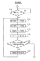
図7は、中央管理装置20の処理の一例を示すフローチャートである。端末装置30から上記の生データ、すなわち、保守用生データ、校正用生データおよび測定生データの受信があると(S201:YES)、データのID符号をチェックして、どの患者に関するデータであるかが特定される(S202)。次いで、保守用生データの値が基準値と比較され、その偏差が第1の設定値以下であるかどうかが判断される(S203)。すなわち、すべての端末装置30に装備された同一規格の保守用サンプルを計測して得られるべき生データの基準値と、実際に各端末装置30から送信されてきた保守用生データとが比較されるのであって、これらの間に偏差が存在する場合は、その端末装置30から送られてくる生データには、端末装置30の増幅部45の出力レベルのずれに起因する誤差が含まれていることを意味する。この誤差が増幅部45のゲインのずれによるものである場合には、上記保守用生データの値を基準値で除して誤差係数を得、測定生データをこの誤差係数で除することにより、測定生データから誤差が除かれる。上記S203において、保守用生データの値と基準値との偏差が第1の設定値以下である場合には、S204において、上記誤差係数を用いて測定生データから誤差を除去する測定生データ調整が行われる。なお、各端末装置30間の増幅部45の出力レベルのずれには、上記のようなゲインのずれのほか、オフセット量のずれが含まれる場合もあるが、このような場合の出力レベルを調整するためには、少なくとも2種の基準サンプル42Aを測定して増幅部45の線型特性を調べ、この線型特性に基づいて測定生データの調整を行うことになる。なお、調整するべき生データとしては、測定サンプル42から得られる測定生データと、校正用サンプル42Bから得られる校正用生データがある。いずれも、出力レベルのずれが生じる増幅部45を介して出力されたものだからである。
【0038】
次いで、上記のように調整された測定生データから、測定データの演算(校正)を行う(S205)。具体的には、2種の校正用サンプル42Bから得られた上記の調整後の校正用生データによって検量線を作成し、この検量線から、上記調整後の測定生データの値に対応する尿中特定成分の濃度を演算する。
【0039】
こうして得られた臨床データとしての測定データは、集団としての正常範囲に照らして正常であるかどうかが判断され(S206)、異常である場合には(S206:YES)、異常報告が行われる(S214)。具体的には、この異常報告は、異常報告信号を端末装置30に送信してその表示部39に表示させたり、その患者の担当医師が所属する医療機関60に通信によって報告するなどして行われる。そして、医療機関60に上記の異常報告が行われる場合には、あわせて、上記の異常データもまた、当該医療機関60に転送される(S215)。
【0040】
そして、上記臨床データは、個人別統計処理(S207)および集団統計処理(S208)に付される。すなわち、個人別統計処理においては、同一のID符号ごとに臨床データを蓄積してゆき、所定の統計処理が行われる。長期の在宅治療を行う場合、上記臨床データを個人別に蓄積してゆくことにより、その患者個人としての正常範囲を規定することができるようになり、その正常範囲は、通常、集団としての正常範囲より狭い。したがって、このような個人別の正常範囲に照らして毎回採集される臨床データをチェックすることにより、在宅患者の健康状態の変化をきめ細かく管理することができるようになる。また、集団統計処理においては、ID符号にかかわりなく、すべての臨床データについて、所定の統計処理が行われ、集団としての正常範囲が規定される。
【0041】
S203において、保守用生データの基準値に対する偏差が第1の設定値よりも大きい場合には(S203:NO)、この保守用生データの基準値に対する偏差が第2の設定値以下であるかどうかが判断される(S211)。通常、第2の設定値は第1の設定値よりも大きく設定される。上記偏差が第2の設定値以下である場合には(S211:YES)、端末装置30に対し、増幅条件変更およびデータ再送信指令が送信される(S212)。すなわち、この実施形態においては、端末装置30から送信されてくる保守用生データの出力レベルのずれが比較的小さい場合には、前述したように中央管理装置20の内部処理において各生データのデータ調整で対応するが、上記出力レベルのずれが比較的大きい場合には、中央管理装置20でのデータ調整で対応するのではなく、端末装置30の増幅部45の増幅条件の変更によって対応する。このような増幅条件の変更およびデータ再送信指令を受信した端末装置30内での処理については、前述したとおりである。端末装置30からは、増幅条件変更後に採集した測定生データ、校正用生データが再送信されてくるが、この場合には、S201〜S203の処理が再度実行される。
【0042】
S211において、上記保守用生データの基準値に対する偏差が第2の設定値よりも大きい場合には(S211:NO)、端末装置30が保守点検を必要とする程度に不調をきたすにいたったものとして、端末異常報知がなされる(S213)。具体的には、この端末異常報知は、この分散型健康管理システム10のシステム保守会社、端末装置30、あるいは関連医療機関60などに対して行われ、医療事故防止措置が講じられる。
【0043】
保守用生データや増幅条件変更の履歴は、端末別保守データ統計処理に付され、たとえば、基準値に対する偏差が、経時的にどのように変化しているか、あるいは、増幅条件変更がどのような経緯でなされたかが記録される。このような統計処理によって、たとえば、保守用生データの偏差の変化傾向の予測が可能となり、これにより、端末装置30の保守点検時期の予測等が可能となる。
【0044】
保守用生データや増幅条件変更の履歴はまた、全端末装置30を対象とした保守データ統計処理に付される(S210)。これにより、たとえば、保守用生データの基準値からの偏差の全体的な傾向が判り、このような情報は、システム保守に有効に利用することができる。
【0045】
以上説明してきたように、本実施形態に係る分散型健康管理システム10においては、各端末装置30がそれぞれ備える生データ採集部40と、中央管理装置20が備えるデータ演算手段210とが協働して完結した臨床検査機能を発揮する。すなわち、生データを用いて演算を実行して臨床データとして意味をもつ測定データを得る機能は、大型コンピュータによって構成される中央管理装置20が一括して担当する。したがって、患者の自宅に設置するべき端末装置30は、生データ採集機能と、データ送信機能という必要最小限の機能を備えた簡単なものとして構成することができる。そのため、端末装置30は比較的安価なものとなり、この種の在宅健康管理サービス、あるいは在宅治療支援サービスを希望する患者は、比較的経済的負担少なく、このようなサービスを受けることが可能となる。
【0046】
そして、上記のような端末装置30を安価に提供できることは、臨床データの統計処理の面からも、きわめて意義深い。すなわち、多数設置された端末装置30から送信されてくる多くのデータを母集団とすることができるので、より精度のよい統計処理が可能となる。
【0047】
さらには、各端末装置30ごとの出力レベルのずれに起因するデータの誤差は、たとえば、各端末装置30に装備させた同一規格の基準サンプル42Aを測定して得られる保守用生データを用いて、たとえばこの保守用生データを中央管理装置20内で基準値と比較し、その結果にもとづいて測定生データを調整するという、簡単な手法によって実質的に除去することができる。また、誤差の傾向によって、端末装置30の異常を中央管理装置20が把握することもできる。したがって、中央管理装置20に蓄積されるとともに患者の健康状態の把握に使用され、かつ統計処理される臨床データとしての測定データの信頼性を著しく高めることができる。また、膨大数の端末装置30を中央管理装置20につなげて分散型の検査・測定システムを構築する場合において、各端末装置30の保守管理が著しく簡略化される。このように、統計処理を前提とし、膨大数の端末装置30をもち、しかも信頼性のある分散型検査・測定システムの実現が、本願発明によって初めて可能となる。
【0048】
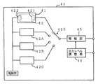
もちろん、本願発明の範囲は上述した実施形態に限定されるものではない。たとえば、各端末装置30が備える生データ採集部40として、上記の実施形態では、図3に示されるように、分光分析の手法によってサンプル中の特定成分の測定を行うべく生データを採集しているが、電気化学的手法によって生データを採集する場合には、図8に示すように構成することができる。すなわち、測定電極421と、対極422とを備えるサンプル装填部41と、濃度の違いに対応した複数の基準抵抗42A,42B,42Cとが並列に配置され、これらサンプル装填部41と各基準抵抗42A,42B,42Cは、切り換えスイッチ42Sを介して増幅部45に切り換え接続可能となっている。増幅部45は、出力レベル調整部46によって中央管理装置20からの指令によって出力レベルを調整しうる。この場合、複数の基準抵抗のいずれか一つまたは複数が基準用サンプルとして機能し、いずれか一つまたは複数がデータ校正用サンプルとして機能する。
【0049】
また、実施形態においては、端末装置30において生データを採集し、これを中央管理装置20に送って処理するようにしているが、可能であれば、たとえば臨床的な意味をもつ測定データを各端末装置30で得て、これを中央管理装置20に送信して統計処理するような場合にも、同様に本願発明を適用することができる。要するに、本願発明は、中央管理装置20においてデータ調整、すなわち、増幅部45の出力レベルのずれに起因するデータ上の誤差の調整をするために、基準サンプル42Aを各端末装置30で測定して保守用データを採集するようにしたものであり、かかる思想を採用するすべての分散型検査・測定システムは、すべて本願発明の範囲に包摂される。
【0050】
さらに、校正用データを用いて中央管理装置20において校正を行う手段として、多変量回帰分析法を用いて複数の尿中成分を同時に定量分析する場合も、もちろん本願発明の範囲に包摂される。
【0051】
さらに、上記述の実施形態では、端末装置30において、測定サンプル42の生データ採集を行うたびごとに、毎回基準サンプル42Aの生データ、すなわち、端末装置30の保守のための生データを採集して中央管理装置20に送信するようにしているが、たとえば、逐次、中央管理装置20からの指令にしたがって、保守用生データを採集してこれを中央管理装置20に送信するようにしてもよいし、定期的に保守用生データを採集して、これを中央管理装置20に送信するようにしてもよい。
【図面の簡単な説明】
【図1】 本願発明の分散型検査・測定システムの一例としての分散型健康管理システムの概念図である。
【図2】 上記分散型健康管理システムを構成する端末装置のブロック図である。
【図3】 上記端末装置が有する生データ採集部(分光分析手段)の構成例の概略図である。
【図4】 上記分散型健康管理システムを構成する中央管理装置のブロック図である。
【図5】 上記分散型健康管理システムを構成する端末装置および中央管理装置の機能ブロック図である。
【図6】 上記端末装置における処理の一例を示すフローチャートである。
【図7】 上記中央管理装置における処理の一例を示すフローチャートである。
【図8】 上記端末装置が有する生データ採集部(電気化学的手法)の構成例の概略図である。
【符号の説明】
10 分散型健康管理システム
20 中央管理装置
30 端末装置
40 生データ採集部
41 サンプル装填部
42A 基準サンプル
42B 校正用サンプル
50 保守用データ採集手段
210 データ演算手段
214 データ調整手段
220 臨床データ管理手段
230 システム管理手段
233 端末データ出力レベル調整手段[0001]
[Technical field to which the invention belongs]
The present invention relates to a distributed inspection / measurement system configured by connecting a plurality of inspection / measurement terminal devices to a central management device via a communication line. The present invention relates to a configuration in which data transmitted from a plurality of terminal devices can be managed centrally in a central management device in response to changes.
[0002]
BACKGROUND OF THE INVENTION
For example, long-term treatment such as diabetes and liver disease Cost As a system for managing such patients while staying at home or supporting home medical care in order to reduce the physical burden of patients with chronic diseases, as shown in JP-A-2-279056, a diabetic patient It has been proposed that blood glucose level data can be transmitted and input to a central microcomputer via a telephone line so that data can be stored for each patient and managed as group data.
[0003]
In the above system, terminal devices are installed in a large number of patient homes, and health management for each patient is performed by clinical data such as blood glucose level data transmitted from each terminal device to a central microcomputer via a telephone line. Or collect it as group data and perform statistical processing.
[0004]
By the way, the terminal device installed in the patient's home is initially adjusted so that each terminal can detect accurate clinical data, but the terminal device installation environment and use conditions are different. Therefore, for example, the output level may change over time, and it is necessary to periodically perform maintenance and inspection.
[0005]
However, when the number of installed terminal devices increases, it becomes difficult to perform regular maintenance and inspection work as described above by dispatching personnel.
[0006]
The present invention has been conceived under such circumstances, and a distributed inspection / measurement system is constructed by connecting a plurality of inspection / measurement terminal devices to a central management device via a communication line. In this case, it is an object of the present invention to enable the central management device to perform accurate data management in response to the difference in characteristics of each terminal device and changes with time.
[0007]
DISCLOSURE OF THE INVENTION
In order to solve the above problems, the present invention employs the following technical means.
[0008]
The distributed inspection / measurement system according to the present invention includes a central management device and a plurality of inspection / measurement terminal devices that can be connected to the central management device via a communication line. A data collection unit that collects data from a sample; and a data transmission unit that transmits data collected by the data collection unit to the central management device. The data collection unit includes: Installed in this data collection department Maintenance data collecting means for measuring a reference sample and collecting maintenance data is provided, and the central management device compares the maintenance data received from the terminal device with a reference value. Other than the maintenance data transmitted from the terminal device It is characterized by comprising data adjustment means for adjusting data.
[0009]
Each terminal device measures a sample to be measured and collects measurement data. At the same time, the terminal device measures a reference sample installed in advance in the data collection unit, and collects the data as maintenance data. These measurement data and maintenance data are transmitted to the central management apparatus via a communication line. In the system according to the present invention, when a plurality of terminal devices are connected to the central management device via a communication line and the central management device performs statistical processing of measurement data, the number of installed terminal devices is enormous. There are numbers. Even in this case, the reference sample provided in each terminal device is a sample of the same standard.
[0010]
By the way, when the data collection unit of the terminal device is configured to amplify the output from the sensor unit by the amplification unit, a reference sample of the same standard is obtained due to variations in initial settings for each terminal device and changes over time. Even in the case of measurement, the output level of the amplifying unit may vary. That is, the gain and offset amount of the amplification unit may be different for each terminal device. In the present invention, the maintenance data obtained from the reference sample is compared with the reference value corresponding to the reference sample in the central management device, and the data is adjusted. Specifically, for example, when adjusting only the gain of the amplifying unit, a ratio between the value of the maintenance data and the reference value is used as an error coefficient, and the sample to be measured is measured using the error coefficient. It adjusts the data that is obtained. When adjusting to the offset amount, two types of reference samples are measured, a function representing the characteristics of the amplification unit in the terminal device is specified, and data is adjusted using this function.
[0011]
In a preferred embodiment, each terminal device collects sample raw data and transmits it to the central management device, and the central management device is configured to obtain the measurement data by calculating the raw data. In this case, data obtained by measuring the reference sample is also raw data. In the central management device, the data is adjusted at the raw data stage or adjusted at the post-computation data stage.
[0012]
In any case, as a result of such a configuration, according to the distributed inspection / measurement system according to the present invention, the number of inspection / measurement terminal devices is enormous, and the characteristics of each terminal device vary with time. Even if there is an error in the measurement data due to a general change, the central management device can unify such errors in the data centrally without requiring maintenance work for each terminal device. Accurate measurement data can be accumulated.
[0013]
In a preferred embodiment, the raw data collection unit in each terminal device measures a calibration sample and collects calibration raw data necessary for calculating measurement data from the measurement raw data. The data calculation means in the central management device further includes measurement raw data received from each terminal device or measurement raw data adjusted by the data adjustment means, and calibration raw data received from each terminal device. Data calculation means for generating measurement data using the data is included.
[0014]
That is, for example, when the system of the present invention is configured to measure the concentration of a specific component in urine by spectroscopic analysis, each terminal device is mainly caused by variations in the output level of the amplification unit as described above. In addition to the reference sample used for centrally correcting the error in the data to be processed in the central management device, for example, preferably a plurality of calibration samples having a prescribed concentration are provided in advance. From the calibration raw data obtained from such a calibration sample, the central control unit creates a calibration curve, and in light of this calibration curve, the concentration of the characteristic component in the sample to be measured, that is, the urine sample set by the patient Is calculated. Even in this case, since all the raw data are error-adjusted as described above, the measurement data accumulated in this way is accurate regardless of variations in the characteristics of the amplifying unit for each terminal device. It will be a thing. In the present invention, the raw data means previous output data having the meaning as clinical data in the case of the clinical examination as described above. That is, it is data at a stage where an output value using an optical method, an electrochemical method, a photoacoustic method, or other methods suitable for a measurement object is converted into an electrical signal. The raw data collected in this way is sent to the central management device via the communication line. After the data adjustment as described above is performed for the first time in the central management device, analysis / calculation (calibration) is performed as clinical data. Meaningful measurement data is obtained.
[0015]
In this way, for example, the distributed type in the above example Inspection / Measurement In the system, the terminal device to be installed at the patient's home has a basic function of measuring the test object (including each sample) and generating the raw data, and placing the raw data on a communication line as a central management device. It is not necessary to provide each terminal device with a complicated function of calculating the concentration of a specific component in a measurement sample by an analysis / calculation (calibration) algorithm. .
[0016]
In a preferred embodiment, the raw data collection unit in the terminal device includes an output level adjustment unit that operates according to a command from a central management device, and the central management device receives maintenance raw data received from the terminal device. Terminal data output level adjusting means for issuing a command to adjust the data output level of the terminal device in a predetermined manner when the deviation from the reference value is greater than or equal to a predetermined value. The data output level is adjusted so that there is no deviation from the reference value of the maintenance raw data. Of course, even if this maintenance of the raw data for maintenance cannot be eliminated by adjusting the output level, the accuracy of the measurement data can be ensured by using the data adjustment means built in the central management device together. Can do.
[0017]
In a preferred embodiment, the central management device includes an abnormality notifying means for notifying that the terminal device is abnormal when the deviation from the reference value of the maintenance raw data received from the terminal device is a predetermined value or more. I have.
[0018]
In such a case, the terminal device has malfunctioned to such an extent that the measurement data cannot be corrected, either by adjusting the terminal data output level or by the action of the data adjusting means performed in the central management device. For example, such an abnormality notification is issued to a system maintenance company or a terminal device. Only when such a situation occurs, each terminal device undergoes maintenance and inspection work by maintenance personnel.
[0019]
Other features and advantages of the present invention will become more apparent from the detailed description given below with reference to the drawings.
[0020]
DETAILED DESCRIPTION OF THE INVENTION
The distributed test and measurement system described below is a distributed health management system in which a clinical test terminal device installed in a home of a home patient who needs long-term treatment is connected to a central management device via a communication line. The present invention is applied to the above. FIG. 1 shows the concept of this distributed
[0021]
The distributed
[0022]
FIG. 2 is a block diagram showing a configuration of each
[0023]
The
[0024]
FIG. 3 schematically illustrates a configuration example of the raw
[0025]
The sample loading unit 41 slides between the light emitting unit 43 and the light receiving unit 44 and sequentially guides each sample to the measurement position. At the time of measurement, the light intensity signal received by the light receiving unit 44 is output via the amplification unit 45. More specifically, an electric signal indicating the incident light intensity at the selected wavelength to be incident on the sample and the sample transmitted light intensity at each selected wavelength is input via the amplifying unit 45. Life Output from the
[0026]
Urine sample to be measured 42 The output electrical signal about is the measured raw data and the
[0027]
FIG. 4 is a block diagram showing the configuration of the
[0028]
The
[0029]
As shown in the block diagram of FIG. 5, the
[0030]
In this embodiment, De The data calculating means 210 uses the maintenance raw data transmitted from each
[0031]
In the present embodiment, the clinical data management means 220 includes individual clinical data management means 221 for managing the health status of the patient corresponding to each
[0032]
In the present embodiment, the
[0033]
Next, an example of the operation of the
[0034]
First, FIG. 6 is a flowchart illustrating an example of the operation of the
[0035]
The maintenance raw data, calibration raw data, and measurement raw data are then automatically transmitted to the
[0036]
Next, when an output level change and data re-transmission command is received from the
[0037]
FIG. 7 shows a
[0038]
Next, the measurement data is calculated (calibrated) from the measured raw data adjusted as described above (S205). Specifically, two types of
[0039]
The measurement data as clinical data obtained in this way is judged whether it is normal in view of the normal range as a group (S206), and if abnormal (S206: YES), an abnormality report is made (S206: YES). S214). Specifically, the abnormality report is performed by transmitting an abnormality report signal to the
[0040]
The clinical data is then subjected to individual statistical processing (S207) and population statistical processing (S208). That is, in the individual statistical processing, clinical data is accumulated for each identical ID code, and predetermined statistical processing is performed. When long-term home treatment is performed, it is possible to define the normal range as an individual patient by accumulating the above clinical data for each individual, and the normal range is usually the normal range as a group. Narrower. Therefore, by checking the clinical data collected each time in light of such individual normal ranges, it becomes possible to finely manage changes in the health status of home patients. In the group statistical processing, regardless of the ID code, predetermined clinical processing is performed for all clinical data, and a normal range as a group is defined.
[0041]
In S203, if the deviation of the maintenance raw data from the reference value is larger than the first set value (S203: NO), is the deviation of the maintenance raw data from the reference value equal to or less than the second set value? It is determined whether or not (S211). Usually, the second set value is set larger than the first set value. When the deviation is equal to or less than the second set value (S211: YES), an amplification condition change and data retransmission command is transmitted to the terminal device 30 (S212). That is, in this embodiment, when the deviation of the output level of the maintenance raw data transmitted from the
[0042]
In S211, when the deviation of the maintenance raw data from the reference value is larger than the second set value (S211: NO), the
[0043]
The maintenance raw data and the history of amplification condition change are attached to the maintenance data statistical processing for each terminal. For example, how the deviation from the reference value has changed over time, or how the amplification condition change has changed. It records what was done in the background. By such statistical processing, for example, it is possible to predict the change tendency of the deviation of the maintenance raw data, and thereby it is possible to predict the maintenance and inspection time of the
[0044]
Raw data for maintenance and history of changes in amplification conditions are also available for all terminal devices. 30 (S210). Thereby, for example, the overall tendency of deviation from the reference value of the raw data for maintenance can be known, and such information can be effectively used for system maintenance.
[0045]
As described above, in the distributed
[0046]
And the terminal device as above 30 Can be provided at low cost is also very significant from the viewpoint of statistical processing of clinical data. That is, since a large amount of data transmitted from a large number of installed
[0047]
Further, the error in data caused by the output level deviation for each
[0048]
Of course, the scope of the present invention is not limited to the embodiment described above. For example, as the raw
[0049]
In the embodiment, the
[0050]
Furthermore, using the calibration data, the
[0051]
Further, in the above-described embodiment, the
[Brief description of the drawings]
FIG. 1 is a conceptual diagram of a distributed health management system as an example of a distributed inspection / measurement system of the present invention.
FIG. 2 is a block diagram of a terminal device constituting the distributed health management system.
FIG. 3 is a schematic diagram of a configuration example of a raw data collection unit (spectral analysis means) included in the terminal device.
FIG. 4 is a block diagram of a central management device constituting the distributed health management system.
FIG. 5 is a functional block diagram of a terminal device and a central management device constituting the distributed health management system.
FIG. 6 is a flowchart showing an example of processing in the terminal device.
FIG. 7 is a flowchart showing an example of processing in the central management apparatus.
FIG. 8 is a schematic diagram of a configuration example of a raw data collection unit (electrochemical technique) included in the terminal device.
[Explanation of symbols]
10 Decentralized health management system
20 Central management device
30 Terminal device
40 Raw Data Collection Department
41 Sample loading section
42A Reference sample
42B school Regular sample
50 Maintenance data collection means
210 De Data calculation means
214 Data adjustment means
220 Clinical data management means
230 System management means
233 Terminal data output level adjustment means
Claims (5)
上記各端末装置は、サンプルからデータを採集するデータ採集部と、このデータ採集部が採集したデータを上記中央管理装置に送信するデータ送信手段とを備えており、
上記データ採集部は、このデータ採集部に設置された基準サンプルを測定して保守用データを採集する保守用データ採集手段を備えており、
上記中央管理装置は、上記端末装置から受信した保守用データを基準値と比較して、当該端末装置から送信されてくる上記保守用データ以外のデータを調整するデータ調整手段を備えていることを特徴とする、分散型検査・測定システム。A central management device and a plurality of inspection / measurement terminal devices connectable to the central management device via a communication line;
Each terminal device includes a data collection unit that collects data from a sample, and a data transmission unit that transmits data collected by the data collection unit to the central management device,
The data collection unit includes maintenance data collection means for measuring a reference sample installed in the data collection unit and collecting maintenance data,
The central management device includes data adjustment means for comparing maintenance data received from the terminal device with a reference value and adjusting data other than the maintenance data transmitted from the terminal device. A featured distributed inspection and measurement system.
上記各端末装置は、サンプルから生データを採集する生データ採集部と、この生データ採集部が採集した生データを上記中央管理装置に送信するデータ送信手段とを備えており、
上記生データ採集部は、基準サンプルを測定して保守用生データを採集する保守用生データ採集手段を備えており、
上記中央管理装置は、上記各端末装置から受信した測定生データを演算して測定データを生成するデータ演算手段と、上記各端末装置から受信した保守用生データを基準値と比較して上記測定生データを調整するか、または、上記保守用生データから演算される保守用データを基準値と比較して上記測定データを調整するデータ調整手段を備えていることを特徴とする、分散型検査・測定システム。A central management device and a plurality of inspection / measurement terminal devices connectable to the central management device via a communication line;
Each of the terminal devices includes a raw data collection unit that collects raw data from a sample, and a data transmission unit that transmits the raw data collected by the raw data collection unit to the central management device,
The raw data collection unit includes maintenance raw data collection means for measuring a reference sample and collecting maintenance raw data.
The central management device calculates the measurement raw data received from each terminal device to generate measurement data, and compares the maintenance raw data received from each terminal device with a reference value to measure the measurement data. A distributed inspection characterized by comprising raw data adjustment means or data adjustment means for adjusting the measurement data by comparing maintenance data calculated from the maintenance raw data with a reference value・ Measurement system.
上記中央管理装置における上記データ演算手段は、各端末装置から受信した測定生データまたは上記データ調整手段によって調整された測定生データと、各端末装置から受信した校正用生データとを用いて測定データを生成するデータ演算手段を含んでいる、請求項2に記載の分散型検査・測定システム。The raw data collection unit in each of the terminal devices further includes a calibration raw data collection unit that measures a calibration sample and collects calibration raw data necessary to calculate measurement data from the measurement raw data. ,
The data calculation means in the central management device uses the measurement raw data received from each terminal device or the measurement raw data adjusted by the data adjustment means and the calibration raw data received from each terminal device. The distributed inspection / measurement system according to claim 2, further comprising data operation means for generating
上記中央管理装置は、各端末装置から受信した保守用生データの基準値からの偏差が所定以上である場合に、当該端末装置のデータ出力レベルを所定のように調整するべき指令を発する端末データ出力レベル調整手段を備えている、請求項2または3に記載の分散型検査・測定システム。The raw data collection unit in the terminal device includes an output level adjustment unit that operates according to a command from a central management device,
The central management device, when the deviation from the reference value of the maintenance raw data received from each terminal device is greater than or equal to a predetermined value, terminal data that issues a command to adjust the data output level of the terminal device as predetermined The distributed inspection / measurement system according to claim 2, further comprising an output level adjustment unit.
Priority Applications (6)
| Application Number | Priority Date | Filing Date | Title |
|---|---|---|---|
| JP05478097A JP3873092B2 (en) | 1997-03-10 | 1997-03-10 | Distributed inspection and measurement system |
| US09/214,966 US6221009B1 (en) | 1996-07-16 | 1997-07-14 | Dispersed-type testing measuring system and dispersed-type care system |
| PCT/JP1997/002441 WO1998002086A1 (en) | 1996-07-16 | 1997-07-14 | Distributed inspection/measurement system and distributed health caring system |
| DE69715255T DE69715255T2 (en) | 1996-07-16 | 1997-07-14 | DISTRIBUTED MONITORING / MEASURING ARRANGEMENT FOR HEALTHCARE |
| EP97930790A EP0958778B1 (en) | 1996-07-16 | 1997-07-14 | Distributed inspection/measurement system and distributed health caring system |
| US09/800,691 US6612986B2 (en) | 1996-07-16 | 2001-03-07 | Dispersed-type testing/measuring system and dispersed-type health care system |
Applications Claiming Priority (1)
| Application Number | Priority Date | Filing Date | Title |
|---|---|---|---|
| JP05478097A JP3873092B2 (en) | 1997-03-10 | 1997-03-10 | Distributed inspection and measurement system |
Publications (2)
| Publication Number | Publication Date |
|---|---|
| JPH10248817A JPH10248817A (en) | 1998-09-22 |
| JP3873092B2 true JP3873092B2 (en) | 2007-01-24 |
Family
ID=12980296
Family Applications (1)
| Application Number | Title | Priority Date | Filing Date |
|---|---|---|---|
| JP05478097A Expired - Fee Related JP3873092B2 (en) | 1996-07-16 | 1997-03-10 | Distributed inspection and measurement system |
Country Status (1)
| Country | Link |
|---|---|
| JP (1) | JP3873092B2 (en) |
Families Citing this family (9)
| Publication number | Priority date | Publication date | Assignee | Title |
|---|---|---|---|---|
| EP1244384B1 (en) * | 1999-12-23 | 2008-06-04 | Philips Intellectual Property & Standards GmbH | Patient-identified measuring |
| EP1167971B1 (en) | 2000-04-17 | 2007-02-07 | Nec Corporation | Method and system for providing a home health care service |
| AU6763200A (en) * | 2000-08-10 | 2001-06-12 | Procter & Gamble | System and method for providing information based on menstrual data |
| US6645142B2 (en) * | 2000-12-01 | 2003-11-11 | Optiscan Biomedical Corporation | Glucose monitoring instrument having network connectivity |
| EP1635282A4 (en) | 2003-06-18 | 2010-11-24 | Panasonic Corp | Biological information utilization system, biological information utilization method, program, and recording medium |
| JP5955680B2 (en) * | 2011-09-02 | 2016-07-20 | アークレイ株式会社 | Nucleic acid detection apparatus, method, and program |
| AU2012330761B2 (en) * | 2011-11-03 | 2016-01-21 | Verifood Ltd. | Low-cost spectrometry system for end-user food analysis |
| CN111161868A (en) * | 2019-12-20 | 2020-05-15 | 贵州铂肴医学检验实验室有限公司 | Medical quick inspection management system |
| US20230138688A1 (en) * | 2021-11-02 | 2023-05-04 | Electronics And Telecommunications Research Institute | Photo-acoustic sensor device and photo-acoustic sensing method of the same |
-
1997
- 1997-03-10 JP JP05478097A patent/JP3873092B2/en not_active Expired - Fee Related
Also Published As
| Publication number | Publication date |
|---|---|
| JPH10248817A (en) | 1998-09-22 |
Similar Documents
| Publication | Publication Date | Title |
|---|---|---|
| US6221009B1 (en) | Dispersed-type testing measuring system and dispersed-type care system | |
| JP2004501380A (en) | Glucose measurement system | |
| US6891936B2 (en) | Remote data control system and measuring data gathering method | |
| US7925461B2 (en) | Quality control system, analyzer, and quality control method | |
| CN105164717B (en) | Process and device for collecting and storing data relating to the condition of an absorbent product | |
| US9135804B2 (en) | Systems and methods for assessing risks of pressure ulcers | |
| JP3873092B2 (en) | Distributed inspection and measurement system | |
| US20080077436A1 (en) | Home based healthcare system and method | |
| JPH10124601A (en) | Distributed health management system | |
| JP2007323528A (en) | Biological information utilizing system | |
| KR100561041B1 (en) | System and method for remote taking care of diabetic | |
| CN111448615A (en) | System and method for processing patient-related medical data | |
| JP3873091B2 (en) | Distributed health management system | |
| JP2671488B2 (en) | Self-collected blood glucose data collection method | |
| US20110153346A1 (en) | Health screen and method for carrying out the health screen | |
| JPH07280803A (en) | Automatic processing method and system for quantity and specific gravity of urine measure in individual sickroom | |
| KR20180013074A (en) | Mobile interworked health check system using urine measuring sensor | |
| JP4109299B2 (en) | Distributed health management system | |
| JP6909678B2 (en) | Medical device management system, medical device management method and medical device management program | |
| CN219480097U (en) | Detection system based on optical waveguide sensor | |
| US20240019452A1 (en) | Control loop-based value adjustment in in-vitro diagnosis systems | |
| WO2022246979A1 (en) | Detection system based on optical waveguide sensor, method, device, and storage medium | |
| CN105303035A (en) | Health monitoring method and system | |
| CN116965807A (en) | System for realizing dynamic continuous monitoring of blood sugar | |
| CN115169986A (en) | Quality control system of clinical laboratory |
Legal Events
| Date | Code | Title | Description |
|---|---|---|---|
| A521 | Written amendment |
Free format text: JAPANESE INTERMEDIATE CODE: A523 Effective date: 20040123 |
|
| A621 | Written request for application examination |
Free format text: JAPANESE INTERMEDIATE CODE: A621 Effective date: 20040123 |
|
| A131 | Notification of reasons for refusal |
Free format text: JAPANESE INTERMEDIATE CODE: A131 Effective date: 20060523 |
|
| A521 | Written amendment |
Free format text: JAPANESE INTERMEDIATE CODE: A523 Effective date: 20060724 |
|
| TRDD | Decision of grant or rejection written | ||
| A01 | Written decision to grant a patent or to grant a registration (utility model) |
Free format text: JAPANESE INTERMEDIATE CODE: A01 Effective date: 20060829 |
|
| A61 | First payment of annual fees (during grant procedure) |
Free format text: JAPANESE INTERMEDIATE CODE: A61 Effective date: 20060913 |
|
| R150 | Certificate of patent or registration of utility model |
Free format text: JAPANESE INTERMEDIATE CODE: R150 |
|
| FPAY | Renewal fee payment (event date is renewal date of database) |
Free format text: PAYMENT UNTIL: 20091102 Year of fee payment: 3 |
|
| FPAY | Renewal fee payment (event date is renewal date of database) |
Free format text: PAYMENT UNTIL: 20101102 Year of fee payment: 4 |
|
| FPAY | Renewal fee payment (event date is renewal date of database) |
Free format text: PAYMENT UNTIL: 20111102 Year of fee payment: 5 |
|
| FPAY | Renewal fee payment (event date is renewal date of database) |
Free format text: PAYMENT UNTIL: 20121102 Year of fee payment: 6 |
|
| FPAY | Renewal fee payment (event date is renewal date of database) |
Free format text: PAYMENT UNTIL: 20131102 Year of fee payment: 7 |
|
| R250 | Receipt of annual fees |
Free format text: JAPANESE INTERMEDIATE CODE: R250 |
|
| R250 | Receipt of annual fees |
Free format text: JAPANESE INTERMEDIATE CODE: R250 |
|
| LAPS | Cancellation because of no payment of annual fees |