JP3871393B2 - Insulating support device and seismic isolation structure using this support device - Google Patents
Insulating support device and seismic isolation structure using this support device Download PDFInfo
- Publication number
- JP3871393B2 JP3871393B2 JP08837897A JP8837897A JP3871393B2 JP 3871393 B2 JP3871393 B2 JP 3871393B2 JP 08837897 A JP08837897 A JP 08837897A JP 8837897 A JP8837897 A JP 8837897A JP 3871393 B2 JP3871393 B2 JP 3871393B2
- Authority
- JP
- Japan
- Prior art keywords
- support device
- rolling
- seismic isolation
- outer ring
- insulating support
- Prior art date
- Legal status (The legal status is an assumption and is not a legal conclusion. Google has not performed a legal analysis and makes no representation as to the accuracy of the status listed.)
- Expired - Lifetime
Links
Images


Description
【0001】
【発明の属する技術分野】
本発明は、構造物を基礎上または直下階で転がり支承で支持し、上部または直上階への外部からの振動の影響を絶縁する絶縁手段を有する直交交差型絶縁支持装置およびこの支持装置を用いる免震構造物に関する。
【0002】
【従来の技術】
一般に、免震構造物の支持装置は、通常、積層ゴムや摩擦スライド等から構成されている。しかるに、この種の支持装置は、構造物の支持のために比較的高い硬度を必要とする。このため、構造物の固有周期を免震に必要な充分な長周期に設定することができず、所期の免震効果が達成されていなかった。
【0003】
また、従来の積層ゴム系免震装置の免震構造では、ねじれ振動に対し抵抗力が小さいため、極力ねじれが生じないような設計が強いられる。すなわち、免震階の偏心率R=0.02となることが推奨される。従って、上部構造体が不整形、例えば、コ型、L型の場合、各棟を切り離して構築する必要が生じ、相互の変形に対して対流する設計を行わなければならない。
【0004】
さらに、従来の積層ゴム系免震装置の免震構造では、引き抜きや浮き上がりに対して殆ど抵抗力を有しない。すなわち、ゴム層のクラック・破断に対しては、引き抜き力をE/2〜E=7〜13kg/cm2以下に抑える設計上の工夫が必要である。従って、スレンダーなノッポビルや塔状構造物および軽量な建物への使用に不向きであり、用途の限界点とされていた。このため、3階建てから15階建て程度の重量構造物への適用に限定された使用法が一般的である。
【0005】
また、従来の積層ゴム系免震装置の免震構造では、周期伸張が大地震時でも3秒程度であり、応答加速度の低減効果が大きく望めない。これは、積層ゴム支承の特性によるものであり、すなわち、周期の伸張を図るためには高面圧すなわち小さな径の装置に重荷重をかけることが必要であり、一方高面圧は地震時または大変形時には装置の「座屈」現象を誘発する恐れがある。これらの理由から、3〜15階建て程度の重量構造物への適応のみが中心となっている。
【0006】
そこで、前記積層ゴム等に代わる免震手段として直動支持装置が提案されている(特開平8−240033号公報)。
【0007】
すなわち、図13および図14において、この直動支持装置10は、基礎12および構造物14に対してそれぞれ固定される転動レール16,18を球形または円筒形の転動子20を介してブロック体22,24に転動自在に連結し、互いに直交するようブロック体22,24を結合して構成される。このような直動支持装置10を単独で又は積層ゴム体などの復元装置25や粘性ダンパーなどの減衰装置27と共に使用することにより、構造物14の基礎12に対する相互移動を可及的低摩擦状態で自由に許容することができ、従って基礎12からの震動伝達を有効に遮断することができる。
【0008】
【発明が解決しようとする課題】
前記直動支持装置における構造物と基礎との間の相互自由移動は、基礎および転動レールの鉛直軸線Zに対する取付水平度すなわち支持装置の取付精度に依存される。換言すれば、水平度が達成されないと、相互自由移動に際して、支持装置の内部に転動レール方向の水平剪断応力(内部応力)fx、fyが発生して、相互自由移動が阻害される。このため、基礎から免震構造物への震動伝達が遮断されなくなる難点がある。しかも、この難点は、免震構造物、特に、不整形や細長い建物内に捩れ現象等が発生すると、直動支持装置の内部には水平剪断応力fx、fyとは別に更に回転捩り力fmが誘発されるので、一層増幅されていた。
【0009】
そこで、本発明の目的は、直動支持装置の取付精度の誤差および構造物の捩れ現象の発生に拘らず、震動遮断および免震効果を充分に達成することができる、絶縁直動支持装置およびこの支持装置を用いる免震構造物を提供することにある。
【0010】
【課題を解決するための手段】
先の目的を達成するために、本発明に係る絶縁支持装置は、基礎に対し固定されて鉛直軸線に対して取付水平度を備えた少なくとも1つの直線状の第1の転動レールと、構造物に対し固定され前記第1の転動レールとは異なる方向に延在する鉛直軸線に対して取付水平度を備えた少なくとも1つの直線状の第2の転動レールと、前記第1および第2の転動レールに摺動可能に連結される転動部材とからなり、前記転動部材は、前記第1の転動レールに摺動可能に第1の転動子を介して連結した第1のブロック体と、前記第2の転動レールに摺動可能に第2の転動子を介して連結した第2のブロック体と、前記第1および第2のブロック体間に介装された絶縁手段としての緩衝体とからなり、前記緩衝体は、弾塑性材料の成形体または封入物の単層または積層物を2枚の硬質部材間に固着したパッド構造体とを有し、前記硬質部材の各々には複数の固定具挿通孔を穿設して、圧縮や引張りの軸力と水平剪断力が作用しても脱落することがなく鉛直軸線に対する取付水平度を有する。
【0012】
また、絶縁手段は緩衝体から構成し、そしてこの緩衝体は、弾塑性材料の成形または封入物の単層または積層物を2枚の硬質部材間に固着してパッドとして構成する。この緩衝体は、矩形パッドまたはリングパッドとして構成される。
【0013】
平面回転体は、外輪と、この外輪に囲繞されかつこれを転動子を介して回転自在に支持する内輪とからなり、平面回転体は、環状溝を備えた外輪と前記環状溝に転動子を介して嵌合される内輪とからなり、緩衝体は、外輪とこの外輪に囲繞されかつこれを転動子を介して回転自在に支持する内輪とからなる平面回転体と、
前記平面回転体の第1および第2の平面の少なくとも一方に取付けられたパッド構造体とからなり、前記パッド構造体は弾塑性材料の成形体又は封入物の単層又は積層物を複数の硬質の部材間に固着した構成を有する。
【0014】
また、パッド構造体は、矩形パッド又はリンク状パッドとして構成され、前記硬質部材の各々には複数の固定具挿通孔を穿設し、さらに前記絶縁支持装置を有する免震構造物を構成することもできる。
【0015】
また、さらに免震構造物は前記絶縁支持装置に加え、減衰装置並びに復元装置を有する。
【0016】
本発明に係る絶縁直動支持装置を免震構造物に適用した場合に、仮にその取付精度の誤差や免震構造物の捩れ現象あるいは免震精度の誤差のためにその内部に水平剪断或いは鉛直捩り等の内部応力が発生しても、この内部応力は、設置された絶縁手段により充分に吸収されて免震構造物に対する基礎からの震動伝達が有効に遮断される。
【0017】
【実施例】
次に、本発明に係る、絶縁支持装置およびこの支持装置を用いる免震構造物の実施例を添付図面を参照しながら以下詳細に説明する。
【0018】
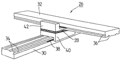
図1および図2において、先ず、本発明に係る絶縁直動支持装置26は、基本的には、構造物を基礎上に転がり支持する直動支持装置であって、その上部構造体に、下部構造体側の振動の上部構造体側への影響を絶縁する絶縁手段28を設ける。
【0019】
すなわち、絶縁直動支持装置26は、基礎および構造物に対してそれぞれ固定される転動レール30,32に、それぞれ長手方向溝34,36を刻設して球形または円筒形の転動子38を収納し、さらにそれぞれの転動レール30,32をブロック体40,42に転動自在に連結して、互いに直交するようブロック体40,42を突合せ結合して構成する。そして、絶縁手段28はブロック体40,42の間に介装される。
【0020】
なお、転動レールとブロック体の連結組合せは、多くの設計変更が可能であり、図2a,bに示すように、球形転動子44を使用したフラット転動面型、図2cに示す円弧状転動面型並びに図2dに示す多角形状転動面型或いは図2eに示す球形および円筒形転動子46を併用したフラット転動面型等に構成することができる。
【0021】
また、絶縁直動支持装置自体の型態は、第1図に示されるそれぞれ単一の基礎および構造物に固定される転動レール30および32からなる十字型態に加えて、例えば、図3aに示すように、2つの基礎に固定される2本の転動レール48,50と単一の構造物に固定される1本の転動レール52とからなるキ字型態や或いは図3bに示す通り、それぞれ2つの基礎および構造物に固定される転動レール52,54並びに56,58とからなる井桁型態等に構成することができる。そして、これらの型態の絶縁直動支持装置は、その支持能力を用途に応じて、例えば、数十Kgの低荷重から数千トンの高荷重に至るまでの広範囲に設計することが可能である。
【0022】
球形または円筒形の鋼製転動体が地震時には、転動ブロック内を循環運動しながら回転するため、摩擦抵抗が極めて小さく駆動することができる。動摩擦係数は、μ=0.003〜0.012と頗る小さく、従来の滑りを利用した免震装置の動摩擦係数の1/10〜1/20に動特性である。また、球形または円筒形の鋼製転動体は、転動レールの側面に配置することによって逆ラジアル(引っ張り)方向にも抵抗することができる。従って、この装置を設置した構造物は、無限周期化した構造物となり、これにコイルバネや従来の積層ゴム系支承で与える復元力特性や粘性ダンパーや高減衰ゴム、鉛入り積層ゴム内の鉛プラグなど減衰特性を与えることができ、従来達成できなかった超長周期化(T≧4秒)された免震構造物も容易に実現可能となり、更なる応答低減効果が発揮できる。
【0023】
次に、本発明に係る絶縁直動支持装置における絶縁手段28について図4を参照して説明すると、この絶縁手段は、緩衝体60からなり、そしてこの緩衝体60は、天然ゴムや高減衰ゴム等の弾塑性材料の成形単層体62(図4a,c)または複層体64(図4b)、或いは流体または粉体ないしは粒状体の封入袋体66(図4d)等からなる中間体を鋼材や硬質プラスチックからなる2枚の取付板68,70に対して加硫接着等で強固に接着してパッド構造体として構成される。そして、取付板68,70には、ボルト貫通孔72を穿設して緩衝体60がブロック40,42に対して容易に取着することができるようにすると共に、絶縁直動支持装置に圧縮や引張りの軸力と水平剪断力が作用しても、脱落することなく所期の目的が達成できるようにする。なお、図示の取付板は矩形に構成されるが、図9および図10に示すように円形に形成してもよい。
【0024】
本発明の前記絶縁直動支持装置を免震構造物に適用した場合に、仮にその取付精度が十分でなくその内部に水平剪断力等の内部応力が発生しても、この内部応力は、その絶縁手段すなわち緩衝体により吸収解消され、地震等の外力が作用した場合、速かに免震装置としての機能を発揮する。従って、免震構造物に対する基礎からの震動伝達が遮断される。そして、この緩衝体は、水平剪断力だけでなく、鉛直震動或いは捩れ現象に対しても有効な吸収機能を果たす。
【0025】
しかしながら、特に鉛直軸に関する回転についてはその回転を許容する能力には限界がある。この場合、上部構造体の不整形さによるねじれ振動が大きく発生することが懸念される構造物に適用した場合には、装置に大きな応力が生じ破壊される危険性があり、またねじれ抵抗による逆応答が上部構造体に発生し、免震効果を損ねる結果となる。
【0026】
そこで、図5乃至図10に本発明に係る絶縁直動支持装置に使用する絶縁手段すなわち緩衝体の別の実施例を示す。
【0027】
まず、図5において、緩衝体は、平面回転体74からなり、外輪76と内輪78とから構成されて、外輪76の内側部に環状溝80を刻設し、一方内輪の外側部にも環状溝82を刻設して転動子84を収納する。
【0028】
つぎに、図6に示される平面回転体85の例は、溝型外輪86の対向側部に複数の環状溝88を刻設し、一方内輪90の両反対側部に対応する複数の環状溝92を刻設して転動子94を収納する。
【0029】
さらに、図7に示す平面回転体96は、図5に示す平面回転体74の外輪76の上表面に、図4で示す構造を有し、かつ図9に示される環状に形成された緩衝体98を取着し、さらに内輪78の下表面にも同様に緩衝体100を取着したものである。
【0030】
また、図8に示す平面回転体102も図7に示す例と同様に図6における平面回転体の外輪86と内輪90にそれぞれ緩衝体104と106とを取着したものである。但し、図7および図8の実施例において、緩衝体が外輪と内輪の双方に取着される構造を説明しているが、外輪か内輪の一方へ緩衝体を取着しても所期の効果が得られる。
【0031】
緩衝体98と104は、地震時の応答に伴う設置部位の回転や施工時の水平レベル誤差に伴う作動の不確実性や性能の安定性を確保し、直交交差型免震装置では不可欠な機能を有する。つまり、応力緩和処置を施さないと、作動が不確実となり、装置の摩擦特性が急上昇し免震装置としての機能を損失する。
【0032】
なお、平面回転体外輪および/または内輪には固定用タップ孔を穿設し、図10に示す通り、直交型直動支持装置26のブロック体40と42との間に装着される。
【0033】
平面回転体を用いることにより、ねじれすなわち鉛直軸に関するトルクに対し無抵抗となり、上部構造体が如何なる平面形状であっても免震化が容易に図れる。この場合、直交交差型免震装置が2組以上に設置されている限りでは、幾何学的検知から直交配置された上下の転動レールは、一直線上に一致することはない。従って、直交交差型絶縁支持装置に平面回転体を装着した場合も、如何なる方向からの地震動に対しても免震効果を発揮することになる。
【0034】
このように構成される本発明に係る絶縁支持装置26は、図11に示すように免震構造物に配置される。なお、図中参照符号108は割栗石、110は耐圧土間コンクリートを示す。そして、図12は本発明に係る絶縁支持装置26を免震構造物に多数配設した状態を示す平面図である。そして、この絶縁支持装置26は単独で使用してもよいが、先に述べたように復元装置25や減衰装置27と併用して免震構造物を得る。
【0035】
【発明の効果】
本発明に係る絶縁支持装置を免震構造物に使用することにより、次のような効果を奏する。
【0036】
▲1▼ ねじれに対し、ほぼ無抵抗でねじれ振動、偏心率が大きくても部材に応力を生ぜしめることなくねじれ振動を許容することができる。
【0037】
▲2▼ 軸方向、軸直交方向の傾きに対しては、ゴムパッドによって緩和でき、摩擦特性に大きな変動をもたらさず摩擦係数の増大を生じさせない。
【0038】
▲3▼ 引き抜きに対しても、抵抗するのでスレンダー、塔状、軽量建物への適用が可能である。
【0039】
▲4▼ 従来の積層ゴム系支承では、免震化が難解であった戸建て住宅や軽量鉄骨造のような軽量構造物の免震化が可能である。
【0040】
▲5▼ 長周期特性の特性がある軟弱地盤上の建物の免震化が可能である。
【0041】
▲6▼ 周期特性の設定が自由で周期4秒以上も容易である。
【0042】
▲7▼ より長周期化された免震構造物が実現でき、応答低減効果の増大が図れる。
【0043】
▲8▼ 上部構造体の平面計画の自由度を増すことができる。
【0044】
▲9▼ 建設コストの低減を図ることができる。
【図面の簡単な説明】
【図1】本発明に係る絶縁直動支持装置の一実施例を示す斜視図である。
【図2】図1に示す転動レールとブロック体の連結組合せを示す断面図であり、(a)は球形の転動子を使用したフラット転動面型の断面図、(b)は別のフラット転動面型の断面図、(c)は円弧状転動面型の断面図、(d)は多角形状転動面型の断面図、(e)は球形および円筒形の転動子を使用したフラット転動面型の断面図である。
【図3】本発明に係る絶縁直動支持装置の別の実施例を示す斜視図であり、(a)はキ字型に組合せた形態を示す斜視図、(b)は井桁型に組合せた形態を示す斜視図である。
【図4】本発明に係る絶縁直動支持装置の絶縁手段(緩衝体)の実施例を示す斜視図であり、(a)は弾塑性材料を単一で使用した緩衝体の斜視図であり、(b)は弾塑性材料を複数使用した緩衝体の斜視図であり、(c)は弾塑性材料を単一で使用した緩衝体の斜視図であり、(d)は封入袋体を使用した緩衝体の斜視図である。
【図5】本発明に係る絶縁直動支持装置に使用する平面回転体型の緩衝体の断面図である。
【図6】別の平面回転体の断面図である。
【図7】緩衝材を取着した図5に示す平面回転体の断面図である。
【図8】緩衝材を取着した図7に示す平面回転体の断面図である。
【図9】環状緩衝体を示す斜視図である。
【図10】本発明に係る平面回転体からなる絶縁支持装置を直交直動装置に装着した状態を示す平面透視図である。
【図11】本発明に係る絶縁直動支持装置を用いる免震構造物を示す要部断面図である。
【図12】本発明に係る絶縁支持装置を免震構造物に多数配設した状態を示す平面図である。
【図13】従来の直動支持装置を示す斜視図である。
【図14】従来の直動支持装置を用いる免震構造物を示す要部断面図である。
【符号の説明】
10 直動支持装置
12 基礎
14 構造物
16,18 転動レール
20 転動子
22,24 ブロック体
26 絶縁直動支持装置
28 絶縁手段
30,32 転動レール
34,36 溝
40,42 ブロック体
44 転動子
46 円筒形転動子
48,50, 転動レール
52,54,56,58 転動レール
60 緩衝体
62 成形単層体
64 複層体
66 封入袋体
68,70 取付板
72 ボルト貫通孔
74 平面回転体
76 外輪
78 内輪
80 環状溝
82 環状溝
84 転動子
86 溝型外輪
88 環状溝
90 内輪
92 環状溝
94 転動子
96 平面回転体
98 緩衝体
100 緩衝体
102 平面回転体
104,106 緩衝体[0001]
BACKGROUND OF THE INVENTION
The present invention uses an orthogonal cross-type insulating support device having an insulating means for supporting a structure with a rolling support on the foundation or directly below the floor and insulating the influence of external vibrations on the upper or directly upper floor, and the support device. Related to seismic isolation structures.
[0002]
[Prior art]
In general, a seismic isolation structure support device is usually composed of laminated rubber, a friction slide, or the like. However, this type of support device requires a relatively high hardness for supporting the structure. For this reason, the natural period of the structure could not be set to a sufficiently long period necessary for base isolation, and the desired base isolation effect was not achieved.
[0003]
In addition, the conventional seismic isolation structure for laminated rubber-based seismic isolation devices is forced to be designed so that twisting does not occur as much as possible because resistance to torsional vibration is small. That is, it is recommended that the eccentricity R of the seismic isolation floor is 0.02. Therefore, when the upper structure is irregular, for example, a U-shape or an L-shape, it is necessary to construct each building separately, and a design for convection against mutual deformation must be performed.
[0004]
Furthermore, the conventional seismic isolation structure of the laminated rubber-based seismic isolation device has almost no resistance to pulling and lifting. That is, for cracking / breaking of the rubber layer, it is necessary to devise a design to keep the pulling force at E / 2 to E = 7 to 13 kg / cm 2 or less. Therefore, it is unsuitable for use in slender Noppo Buildings, tower-like structures, and lightweight buildings, and has been regarded as a limit point of applications. For this reason, the use method limited to application to heavy structures of about 3 to 15 stories is common.
[0005]
Moreover, in the conventional seismic isolation structure of the laminated rubber-based seismic isolation device, the period extension is about 3 seconds even during a large earthquake, and the effect of reducing the response acceleration cannot be greatly expected. This is due to the properties of laminated rubber bearings, i.e. high surface pressure, i.e. heavy loads on small diameter devices, are required to extend the period, while high surface pressure is At large deformations, there is a risk of inducing a “buckling” phenomenon of the device. For these reasons, the main focus is on adaptation to heavy structures of about 3 to 15 stories.
[0006]
Therefore, a linear motion support device has been proposed as a seismic isolation means in place of the laminated rubber (JP-A-8-240033).
[0007]
That is, in FIGS. 13 and 14, the linear
[0008]
[Problems to be solved by the invention]
The mutual free movement between the structure and the foundation in the linear motion support device depends on the mounting level of the foundation and the rolling rail with respect to the vertical axis Z, that is, the mounting accuracy of the support device. In other words, if the level is not achieved, horizontal shear stresses (internal stresses) fx and fy in the direction of the rolling rail are generated inside the support device during mutual free movement, thereby hindering the mutual free movement. For this reason, there is a difficulty that the vibration transmission from the foundation to the base-isolated structure is not cut off. In addition, this problem is that when a torsion phenomenon or the like occurs in a seismic isolation structure, particularly an irregular shape or a long and narrow building, a rotational torsional force fm is further generated inside the linear motion support device in addition to the horizontal shear stresses fx and fy. As it was triggered, it was further amplified.
[0009]
Accordingly, an object of the present invention is to provide an insulated linear motion support device capable of sufficiently achieving a vibration isolation and seismic isolation effect regardless of errors in mounting accuracy of the linear motion support device and occurrence of a twisting phenomenon of the structure, and The object is to provide a seismic isolation structure using this support device.
[0010]
[Means for Solving the Problems]
In order to achieve the above object, an insulating support device according to the present invention includes at least one linear first rolling rail fixed to a foundation and provided with a mounting level with respect to a vertical axis, and a structure. At least one linear second rolling rail having a mounting level with respect to a vertical axis fixed to an object and extending in a direction different from the first rolling rail, and the first and first A rolling member slidably connected to the two rolling rails, the rolling member being slidably connected to the first rolling rail via a first rolling element. A first block body, a second block body slidably connected to the second rolling rail via a second rolling element, and interposed between the first and second block bodies. A buffer body as an insulating means, and the buffer body is formed of a molded body or an enclosure of an elastic-plastic material. A pad structure in which a layer or a laminate is fixed between two hard members, and each of the hard members is provided with a plurality of fixing tool insertion holes, and compressive or tensile axial force and horizontal shearing. Even if force is applied, it does not fall off and has a mounting level with respect to the vertical axis.
[0012]
Further, the insulating means is constituted by a buffer body, and this buffer body is formed as a pad by adhering a single layer or a laminate of an elastic-plastic material or an enclosure between two hard members. This buffer is configured as a rectangular pad or a ring pad.
[0013]
Planar rotating body, outer ring and consists an inner ring rotatably supported via a are surrounded by the outer ring and which rolling element, the planar rotating body, rolling the annular groove and the outer ring having an annular groove A planar rotating body comprising an outer ring and an inner ring that is surrounded by the outer ring and rotatably supports the outer ring via a rotator;
A pad structure attached to at least one of the first and second planes of the plane rotating body, wherein the pad structure is formed of an elastic-plastic material molded body or a single layer or a laminate of inclusions. It has the structure fixed between these members.
[0014]
Further, the pad structure is configured as a rectangular pad or a link pad, and a plurality of fixture insertion holes are formed in each of the hard members, and further , a seismic isolation structure having the insulating support device is configured. You can also.
[0015]
Further, the seismic isolation structure has an attenuation device and a restoring device in addition to the insulating support device.
[0016]
When the insulated linear motion support device according to the present invention is applied to a base-isolated structure, horizontal shear or vertical in the interior due to an error in its mounting accuracy, a twisting phenomenon of the base-isolated structure, or an error in base-isolating accuracy. Even if an internal stress such as torsion occurs, the internal stress is sufficiently absorbed by the installed insulating means, and the vibration transmission from the foundation to the seismic isolation structure is effectively cut off.
[0017]
【Example】
Next, embodiments of an insulating support device and a seismic isolation structure using the support device according to the present invention will be described in detail below with reference to the accompanying drawings.
[0018]
In FIG. 1 and FIG. 2, first, an insulated linear
[0019]
That is, the insulating linear
[0020]
The coupling combination of the rolling rail and the block body can be changed in many designs, as shown in FIGS. 2a and 2b, a flat rolling surface type using a
[0021]
Further, the type of the insulation linear motion support device itself is, for example, as shown in FIG. 3a in addition to the cross type consisting of rolling
[0022]
Since the spherical or cylindrical steel rolling element rotates while circulating in the rolling block during an earthquake, it can be driven with extremely low frictional resistance. The dynamic friction coefficient is as small as μ = 0.003 to 0.012, and the dynamic characteristic is 1/10 to 1/20 of the dynamic friction coefficient of a conventional seismic isolation device using slip. In addition, the spherical or cylindrical steel rolling element can be resisted in the reverse radial (pull) direction by being disposed on the side surface of the rolling rail. Therefore, the structure in which this device is installed becomes a structure with an infinite cycle, and the restoring force characteristics given by the coil spring and the conventional laminated rubber bearings, viscous dampers, high damping rubber, lead plugs in laminated rubber containing lead A seismic isolation structure having a very long period (T ≧ 4 seconds), which could not be achieved in the past, can be easily realized, and a further response reduction effect can be exhibited.
[0023]
Next, the insulating means 28 in the insulating linear motion support device according to the present invention will be described with reference to FIG. 4. The insulating means comprises a
[0024]
When the insulation linear motion support device of the present invention is applied to a seismic isolation structure, even if the mounting accuracy is not sufficient and an internal stress such as a horizontal shearing force is generated therein, the internal stress is Absorption is eliminated by the insulating means, that is, the buffer, and when an external force such as an earthquake is applied, the function as a seismic isolation device is quickly exhibited. Therefore, the vibration transmission from the foundation to the seismic isolation structure is blocked. And this buffer body fulfill | performs an effective absorption function not only with respect to a horizontal shearing force but with respect to a vertical vibration or a twist phenomenon.
[0025]
However, there is a limit to the ability to allow the rotation especially with respect to the rotation about the vertical axis. In this case, when applied to a structure where torsional vibration due to irregularities in the upper structure is likely to occur, there is a risk that the device will be damaged due to large stress, and the reverse due to torsional resistance. Response occurs in the superstructure, resulting in a loss of seismic isolation effect.
[0026]
FIG. 5 to FIG. 10 show another embodiment of the insulating means, that is, the buffer body used in the insulating linear motion support device according to the present invention.
[0027]
First, in FIG. 5, the shock absorber is composed of a
[0028]
Next, in the example of the
[0029]
Further, the
[0030]
Further, similarly to the example shown in FIG. 7, the
[0031]
The
[0032]
In addition, a fixing tapped hole is formed in the outer ring and / or the inner ring of the plane rotating body, and is mounted between the
[0033]
By using a plane rotating body, there is no resistance to torsion, that is, torque related to the vertical axis, and seismic isolation can be easily achieved regardless of the planar shape of the upper structure. In this case, as long as two or more orthogonal crossing type seismic isolation devices are installed, the upper and lower rolling rails orthogonally arranged from the geometric detection do not coincide with each other on a straight line. Therefore, even when the plane rotating body is mounted on the orthogonal crossing type insulation support device, the seismic isolation effect is exhibited against the earthquake motion from any direction.
[0034]
The
[0035]
【The invention's effect】
By using the insulating support device according to the present invention for a seismic isolation structure, the following effects can be obtained.
[0036]
{Circle around (1)} Torsional vibration can be allowed without causing stress to the member even if the torsional vibration and eccentricity are large with almost no resistance against torsion.
[0037]
{Circle around (2)} The inclination in the axial direction and the direction perpendicular to the axis can be relaxed by the rubber pad, and the frictional characteristics are not greatly changed and the friction coefficient is not increased.
[0038]
(3) Since it resists pulling, it can be applied to slender, tower-shaped, lightweight buildings.
[0039]
(4) With conventional laminated rubber bearings, it is possible to make seismic isolation of light-weight structures such as detached houses and lightweight steel structures, where seismic isolation is difficult.
[0040]
(5) Buildings on soft ground with long-period characteristics can be seismically isolated.
[0041]
(6) Periodic characteristics can be set freely and the period can be easily over 4 seconds.
[0042]
(7) A seismic isolation structure with a longer period can be realized, and the response reduction effect can be increased.
[0043]
(8) The degree of freedom in the plan of the superstructure can be increased.
[0044]
(9) Construction cost can be reduced.
[Brief description of the drawings]
FIG. 1 is a perspective view showing an embodiment of an insulated linear motion support device according to the present invention.
2 is a cross-sectional view showing a coupling combination of a rolling rail and a block body shown in FIG. 1, (a) is a cross-sectional view of a flat rolling surface type using a spherical rolling element, and (b) is another. (C) is a cross-sectional view of an arcuate rolling surface type, (d) is a cross-sectional view of a polygonal rolling surface type, and (e) is a spherical and cylindrical rolling element. It is sectional drawing of the flat rolling surface type | mold which used No ..
FIGS. 3A and 3B are perspective views showing another embodiment of the insulation linear motion support device according to the present invention, wherein FIG. 3A is a perspective view showing a combination with a K-shape, and FIG. 3B is a combination with a cross-beam type. It is a perspective view which shows a form.
FIG. 4 is a perspective view showing an embodiment of an insulating means (buffer body) of the insulation linear motion support device according to the present invention, and (a) is a perspective view of the buffer body using a single elastic-plastic material. (B) is a perspective view of a shock absorber using a plurality of elastic-plastic materials, (c) is a perspective view of a shock absorber using a single elastic-plastic material, and (d) uses an encapsulating bag. FIG.
FIG. 5 is a cross-sectional view of a plane rotating body type shock absorber used in the insulated linear motion support device according to the present invention.
FIG. 6 is a cross-sectional view of another planar rotating body.
7 is a cross-sectional view of the planar rotating body shown in FIG.
8 is a cross-sectional view of the plane rotator shown in FIG. 7 with a cushioning material attached.
FIG. 9 is a perspective view showing an annular buffer.
FIG. 10 is a plan perspective view showing a state in which an insulating support device made of a plane rotating body according to the present invention is mounted on an orthogonal linear motion device.
FIG. 11 is a cross-sectional view of an essential part showing a seismic isolation structure using an insulated linear motion support device according to the present invention.
FIG. 12 is a plan view showing a state in which a large number of insulating support devices according to the present invention are arranged in a seismic isolation structure.
FIG. 13 is a perspective view showing a conventional linear motion support device.
FIG. 14 is a cross-sectional view of an essential part showing a seismic isolation structure using a conventional linear motion support device.
[Explanation of symbols]
DESCRIPTION OF
Claims (9)
構造物に対し固定され前記第1の転動レールとは異なる方向に延在する鉛直軸線に対して取付水平度を備えた少なくとも1つの直線状の第2の転動レールと、
前記第1および第2の転動レールに摺動可能に連結される転動部材とからなり、
前記転動部材は、前記第1の転動レールに摺動可能に第1の転動子を介して連結した第1のブロック体と、前記第2の転動レールに摺動可能に第2の転動子を介して連結した第2のブロック体と、前記第1および第2のブロック体間に介装された絶縁手段としての緩衝体とからなり、
前記緩衝体は、弾塑性材料の成形体または封入物の単層または積層物を2枚の硬質部材間に固着したパッド構造体とを有し、前記硬質部材の各々には複数の固定具挿通孔を穿設して、
圧縮や引張りの軸力と水平剪断力が作用しても脱落することがなく鉛直軸線に対する取付水平度を有する絶縁支持装置。At least one linear first rolling rail fixed relative to the foundation and having a mounting level with respect to the vertical axis;
At least one linear second rolling rail having a mounting level with respect to a vertical axis fixed to the structure and extending in a different direction from the first rolling rail;
A rolling member slidably coupled to the first and second rolling rails,
The rolling member includes a first block body slidably connected to the first rolling rail via a first rolling element, and a second block slidable to the second rolling rail. A second block body connected via a rolling element, and a buffer body as an insulating means interposed between the first and second block bodies,
The shock absorber has a pad structure in which a single layer or a laminate of an elastic-plastic material or an inclusion is fixed between two hard members, and each of the hard members has a plurality of fasteners inserted therethrough. Make a hole,
An insulating support device having a mounting level with respect to the vertical axis without falling off even when a compression or tension axial force and horizontal shearing force are applied.
前記平面回転体の第1および第2の平面の少なくとも一方に取付けられたパッド構造体とからなり、前記パッド構造体は弾塑性材料の成形体又は封入物の単層又は積層物を複数の硬質の部材間に固着した構成を有する請求項1記載の絶縁支持装置。The shock absorber is a planar rotating body composed of an outer ring and an inner ring that is surrounded by the outer ring and rotatably supports the outer ring via a rolling element;
A pad structure attached to at least one of the first and second planes of the plane rotating body, wherein the pad structure is formed of an elastic-plastic material molded body or a single layer or a laminate of inclusions. The insulation support device according to claim 1, wherein the insulation support device has a structure fixed between the members.
Priority Applications (1)
| Application Number | Priority Date | Filing Date | Title |
|---|---|---|---|
| JP08837897A JP3871393B2 (en) | 1997-04-07 | 1997-04-07 | Insulating support device and seismic isolation structure using this support device |
Applications Claiming Priority (1)
| Application Number | Priority Date | Filing Date | Title |
|---|---|---|---|
| JP08837897A JP3871393B2 (en) | 1997-04-07 | 1997-04-07 | Insulating support device and seismic isolation structure using this support device |
Publications (2)
| Publication Number | Publication Date |
|---|---|
| JPH10280730A JPH10280730A (en) | 1998-10-20 |
| JP3871393B2 true JP3871393B2 (en) | 2007-01-24 |
Family
ID=13941138
Family Applications (1)
| Application Number | Title | Priority Date | Filing Date |
|---|---|---|---|
| JP08837897A Expired - Lifetime JP3871393B2 (en) | 1997-04-07 | 1997-04-07 | Insulating support device and seismic isolation structure using this support device |
Country Status (1)
| Country | Link |
|---|---|
| JP (1) | JP3871393B2 (en) |
Families Citing this family (10)
| Publication number | Priority date | Publication date | Assignee | Title |
|---|---|---|---|---|
| JP2000283221A (en) * | 1999-03-30 | 2000-10-13 | Tokkyokiki Corp | Base isolation vibration damping device |
| JP4856438B2 (en) * | 2006-02-09 | 2012-01-18 | 三井住友建設株式会社 | Intermediate floor seismic isolation building |
| KR100787494B1 (en) | 2006-03-15 | 2007-12-27 | 황기태 | Vibration Reducing Device |
| JP6013167B2 (en) * | 2012-12-12 | 2016-10-25 | 特許機器株式会社 | Rail sliding type seismic isolation device |
| JP6252126B2 (en) * | 2013-11-18 | 2017-12-27 | 株式会社大林組 | palette |
| JP6535912B2 (en) * | 2013-11-28 | 2019-07-03 | 金剛株式会社 | Seismic isolation table |
| JP6274172B2 (en) * | 2015-09-01 | 2018-02-07 | 大亦 絢一郎 | Seismic isolation table device |
| KR20180022299A (en) * | 2016-08-24 | 2018-03-06 | 지수상 | electric power cable support system for bridge |
| CN111550518A (en) * | 2020-05-19 | 2020-08-18 | 中国航空规划设计研究总院有限公司 | Well-shaped rail shock isolation device and installation method thereof |
| CN115354770B (en) * | 2022-09-26 | 2023-11-24 | 贵州开放大学(贵州职业技术学院) | Anti-seismic building structure assembly |
Family Cites Families (5)
| Publication number | Priority date | Publication date | Assignee | Title |
|---|---|---|---|---|
| JPS58124843A (en) * | 1982-01-20 | 1983-07-25 | Mitsubishi Steel Mfg Co Ltd | Vibration-insulating device |
| JPS6089366U (en) * | 1983-11-19 | 1985-06-19 | 鹿島建設株式会社 | rocking stopper |
| JP2918311B2 (en) * | 1990-08-27 | 1999-07-12 | 住友ゴム工業株式会社 | Anti-vibration device |
| JP3195512B2 (en) * | 1995-03-02 | 2001-08-06 | 住友建設株式会社 | Seismic isolation structure |
| JPH08326841A (en) * | 1995-05-31 | 1996-12-10 | Bridgestone Corp | Base isolation support device |
-
1997
- 1997-04-07 JP JP08837897A patent/JP3871393B2/en not_active Expired - Lifetime
Also Published As
| Publication number | Publication date |
|---|---|
| JPH10280730A (en) | 1998-10-20 |
Similar Documents
| Publication | Publication Date | Title |
|---|---|---|
| KR100384591B1 (en) | Energy absorber | |
| EP2302144B1 (en) | Frictional damper for damping movement of structures | |
| JP2883219B2 (en) | Seismic isolation support device | |
| JP3871393B2 (en) | Insulating support device and seismic isolation structure using this support device | |
| JP4902330B2 (en) | Seismic isolation devices and seismic isolation structures | |
| JP2717143B2 (en) | Vibration control method of buildings by friction | |
| JP4483151B2 (en) | Vertical seismic isolation device | |
| JP4162078B2 (en) | Seismic isolation device | |
| JP4439694B2 (en) | High-damping frame of high-rise building | |
| JP3713645B2 (en) | Seismic isolation device using laminated rubber | |
| JP3671317B2 (en) | Seismic isolation mechanism | |
| JPH10246281A (en) | Damping device for base isolation structure | |
| JP3875228B2 (en) | Seismic isolation device | |
| JPH0262670B2 (en) | ||
| JP2011141010A (en) | Base isolation construction and structure | |
| JPH033723Y2 (en) | ||
| JPH04154B2 (en) | ||
| JP2003097086A (en) | Base isolation building and construction method therefor | |
| JP2662621B2 (en) | Friction damper | |
| JP2002047827A (en) | Base isolation structure | |
| JP2002201816A (en) | Base isolation foundation structure of building | |
| JP4695650B2 (en) | Seismic isolation and control equipment | |
| JP2022162399A (en) | Support device | |
| JPH0542202Y2 (en) | ||
| JP2005344508A5 (en) |
Legal Events
| Date | Code | Title | Description |
|---|---|---|---|
| A521 | Written amendment |
Free format text: JAPANESE INTERMEDIATE CODE: A523 Effective date: 20040401 |
|
| A621 | Written request for application examination |
Free format text: JAPANESE INTERMEDIATE CODE: A621 Effective date: 20040401 |
|
| A977 | Report on retrieval |
Free format text: JAPANESE INTERMEDIATE CODE: A971007 Effective date: 20050916 |
|
| A131 | Notification of reasons for refusal |
Free format text: JAPANESE INTERMEDIATE CODE: A131 Effective date: 20060111 |
|
| A521 | Written amendment |
Free format text: JAPANESE INTERMEDIATE CODE: A523 Effective date: 20060310 |
|
| A02 | Decision of refusal |
Free format text: JAPANESE INTERMEDIATE CODE: A02 Effective date: 20060630 |
|
| A521 | Written amendment |
Free format text: JAPANESE INTERMEDIATE CODE: A523 Effective date: 20060829 |
|
| A911 | Transfer of reconsideration by examiner before appeal (zenchi) |
Free format text: JAPANESE INTERMEDIATE CODE: A911 Effective date: 20060905 |
|
| TRDD | Decision of grant or rejection written | ||
| A01 | Written decision to grant a patent or to grant a registration (utility model) |
Free format text: JAPANESE INTERMEDIATE CODE: A01 Effective date: 20060929 |
|
| A61 | First payment of annual fees (during grant procedure) |
Free format text: JAPANESE INTERMEDIATE CODE: A61 Effective date: 20061017 |
|
| R150 | Certificate of patent or registration of utility model |
Free format text: JAPANESE INTERMEDIATE CODE: R150 |
|
| FPAY | Renewal fee payment (event date is renewal date of database) |
Free format text: PAYMENT UNTIL: 20121027 Year of fee payment: 6 |
|
| FPAY | Renewal fee payment (event date is renewal date of database) |
Free format text: PAYMENT UNTIL: 20121027 Year of fee payment: 6 |
|
| FPAY | Renewal fee payment (event date is renewal date of database) |
Free format text: PAYMENT UNTIL: 20151027 Year of fee payment: 9 |
|
| R250 | Receipt of annual fees |
Free format text: JAPANESE INTERMEDIATE CODE: R250 |
|
| R250 | Receipt of annual fees |
Free format text: JAPANESE INTERMEDIATE CODE: R250 |
|
| EXPY | Cancellation because of completion of term |